WO2024204613A1 - 継手装置及び駆動装置 - Google Patents
継手装置及び駆動装置 Download PDFInfo
- Publication number
- WO2024204613A1 WO2024204613A1 PCT/JP2024/012824 JP2024012824W WO2024204613A1 WO 2024204613 A1 WO2024204613 A1 WO 2024204613A1 JP 2024012824 W JP2024012824 W JP 2024012824W WO 2024204613 A1 WO2024204613 A1 WO 2024204613A1
- Authority
- WO
- WIPO (PCT)
- Prior art keywords
- gear
- internal
- rotating body
- coupling device
- power
- Prior art date
- Legal status (The legal status is an assumption and is not a legal conclusion. Google has not performed a legal analysis and makes no representation as to the accuracy of the status listed.)
- Ceased
Links
Images


Classifications
-
- F—MECHANICAL ENGINEERING; LIGHTING; HEATING; WEAPONS; BLASTING
- F16—ENGINEERING ELEMENTS AND UNITS; GENERAL MEASURES FOR PRODUCING AND MAINTAINING EFFECTIVE FUNCTIONING OF MACHINES OR INSTALLATIONS; THERMAL INSULATION IN GENERAL
- F16H—GEARING
- F16H1/00—Toothed gearings for conveying rotary motion
- F16H1/02—Toothed gearings for conveying rotary motion without gears having orbital motion
- F16H1/04—Toothed gearings for conveying rotary motion without gears having orbital motion involving only two intermeshing members
- F16H1/06—Toothed gearings for conveying rotary motion without gears having orbital motion involving only two intermeshing members with parallel axes
-
- F—MECHANICAL ENGINEERING; LIGHTING; HEATING; WEAPONS; BLASTING
- F16—ENGINEERING ELEMENTS AND UNITS; GENERAL MEASURES FOR PRODUCING AND MAINTAINING EFFECTIVE FUNCTIONING OF MACHINES OR INSTALLATIONS; THERMAL INSULATION IN GENERAL
- F16H—GEARING
- F16H1/00—Toothed gearings for conveying rotary motion
- F16H1/02—Toothed gearings for conveying rotary motion without gears having orbital motion
- F16H1/04—Toothed gearings for conveying rotary motion without gears having orbital motion involving only two intermeshing members
- F16H1/12—Toothed gearings for conveying rotary motion without gears having orbital motion involving only two intermeshing members with non-parallel axes
- F16H1/16—Toothed gearings for conveying rotary motion without gears having orbital motion involving only two intermeshing members with non-parallel axes comprising worm and worm-wheel
-
- F—MECHANICAL ENGINEERING; LIGHTING; HEATING; WEAPONS; BLASTING
- F16—ENGINEERING ELEMENTS AND UNITS; GENERAL MEASURES FOR PRODUCING AND MAINTAINING EFFECTIVE FUNCTIONING OF MACHINES OR INSTALLATIONS; THERMAL INSULATION IN GENERAL
- F16H—GEARING
- F16H1/00—Toothed gearings for conveying rotary motion
- F16H1/28—Toothed gearings for conveying rotary motion with gears having orbital motion
- F16H1/32—Toothed gearings for conveying rotary motion with gears having orbital motion in which the central axis of the gearing lies inside the periphery of an orbital gear
Definitions
- the present invention relates to a coupling device and a drive device.
- Patent Document 1 describes a method in which a sensor that detects the contraction movement of the muscles in the stump of the amputated leg is provided in the thigh socket of the prosthetic leg that is attached to the stump of the amputated leg, and the degree of throttling of the variable valve of the hydraulic cylinder that adjusts the resistance of flexion and extension of the knee joint is controlled by the detection information from the sensor.
- Patent Document 2 describes an internal planetary gear mechanism.
- the prosthetic limb described in Patent Document 1 could generate resistance to flexion and extension, but was unable to generate power for flexion and extension. In particular, in order to climb stairs smoothly, it was necessary to extend the knee joint while a load was applied.
- the present invention provides a coupling device that can extend and bend a connecting portion using the power of a power source, and a drive unit that is compact and can provide a large gear ratio.
- the present invention relates to A first member; A second member; a connecting portion that connects the first member and the second member in such a manner that an angle between the first member and the second member can be changed;
- the expansion/contraction device is A drive device and a power transmission unit that transmits power of the drive device
- the power transmission unit includes: a first power transmission path that transmits the power at a first gear ratio; a second power transmission path that transmits the power at a second speed ratio different from the first speed ratio,
- the expansion/contraction device is a first interrupting mechanism that switches between interruption and connection of power in the first power transmission path; a second interrupting mechanism that switches between interruption and connection of power in the second power transmission path,
- the drive device is a drive unit, a speed change unit that is provided so as to be capable of transmitting power to the drive unit, and a housing member that houses the drive unit and the speed change unit,
- the present invention also provides a method for producing a method for manufacturing a semiconductor device comprising the steps of: A drive device including a drive unit, a speed change unit that is provided so as to be capable of transmitting power to the drive unit, and a housing member that houses the drive unit and the speed change unit,
- the transmission unit includes: a first rotating body and a second rotating body rotatably supported by the housing member; an internal planetary gear mechanism disposed on a power transmission path of the first rotating body and the second rotating body,
- the internal planetary gear mechanism is an annular internal gear having internal teeth on an inner periphery thereof; an external gear having an outer periphery with a smaller number of external teeth than the internal teeth, the external gear being disposed inside the internal gear and meshing with the internal gear;
- the rotating element has an eccentric hole therein and supports the internal gear arranged inside the eccentric hole so that the internal gear can oscillate.
- the coupling device of the present invention allows the connecting portion to be extended and bent via the power transmission portion that transmits the power of the drive device.
- the drive device of the present invention can achieve a large gear ratio with a small size.
- FIG. 1 is a perspective view of an electric prosthetic leg 1 according to an embodiment of the present invention, as viewed obliquely from behind.
- FIG. 2 is a side view of the electric prosthetic leg 1 of FIG. 2 is a perspective view of an expansion/contraction device 200 of a first embodiment that can be mounted on the electric prosthetic leg 1 of FIG. 1 .
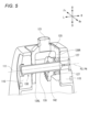
- FIG. 4 is a cross-sectional view of the expansion/contraction device 200 of FIG. 3 . 4 is a cross-sectional oblique view of a knee joint mechanism 130 of an electric prosthetic leg 1 incorporating the expansion/contraction device 200 of FIG. 3.
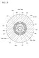
- 2 is a cross-sectional view of a two-way clutch 280.
- FIGS. 1A and 1B are diagrams showing the operation of the operating mechanism 240, in which (A) is a diagram showing the state in which the intermittent portion 212 and the intermittent portion 222 are off, (B) is a diagram showing the state in which the intermittent portion 212 is on and the intermittent portion 222 is off, and (C) is a diagram showing the state in which the intermittent portion 212 is off and the intermittent portion 222 is on.
- 13A is a cross-sectional view showing a state in which the interrupter 212 is in an OFF state
- FIG. 13B is a diagram showing the position of the operating rod 241 at that time.
- 13A is a cross-sectional view showing a state in which the interrupter 212 is operated from OFF to ON
- 13B is a diagram showing the position of the operating rod 241 at that time.
- 1A is a cross-sectional view showing the forward rotation on state of the interrupter 212
- FIG. 1B is a diagram showing the position of the operating rod 241 at that time.
- 1A is a cross-sectional view showing the reverse ON state of the interrupter 212
- FIG. 1B is a diagram showing the position of the operating rod 241 at that time.
- 13A is a cross-sectional view showing a state in which the interrupter 212 is operated from on to off
- FIG. 13B is a diagram showing the position of the operating rod 241 at that time.
- 2 is a perspective view of an expansion/contraction device 200A of a second embodiment that can be mounted on the electric prosthetic leg 1 of FIG.
- FIG. 15 is a cross-sectional view of the expansion/contraction device 200A of FIG. 14.
- 13 is a cross-sectional oblique view of a knee joint mechanism 130 of an electric prosthetic leg 1 incorporating an expansion/contraction device 200A of a second embodiment.
- FIG. 4 is a perspective view of an expansion/contraction device 200B of a third embodiment that can be mounted on the electric prosthetic leg 1 of FIG.
- FIG. 18 is a cross-sectional view of the expansion/contraction device 200B of FIG. 17.
- 19 is an enlarged view of the planetary gear mechanism 260 in the expansion/contraction device 200B of FIG. 18. This is a cross-sectional view taken along line BB of Figure 19.
- FIGS. 1A to 1C are diagrams illustrating the movement of a user and an electric prosthetic leg when ascending steps (step-ascending movement). 1A to 1C are diagrams illustrating the movement of a user and an electric prosthetic leg when walking on flat ground (flat ground walking movement).
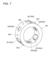
- FIG. 2 is a cross-sectional view of the actuator M.
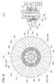
- FIG. 25 is a cross-sectional view of line AA in FIG. 24. 25 is a cross-sectional view taken along line BB of FIG. 24. 13 is a cross-sectional view of a modified example of the actuator M.
- an electric prosthetic leg which is one embodiment of the joint device of the present invention, will be described with reference to the drawings.
- the front-rear direction, left-right direction, and up-down direction are defined based on the user of the electric prosthetic leg.
- the front of the electric prosthetic leg is indicated as Fr, the rear as Rr, the left side as L, the right side as R, the top as U, and the bottom as D.
- the electric prosthetic leg 1 is a prosthetic leg that is attached to the leg of a person without a knee, and includes a below-knee member 110 located below the knee, an above-knee member 120 attached to the thigh and located above the knee, a knee joint mechanism 130 that connects the below-knee member 110 and the above-knee member 120 in a manner that allows the angle between them to be changed, an expansion/contraction device 200 that can expand and contract the angle between the below-knee member 110 and the above-knee member 120, and a battery B that supplies power to the expansion/contraction device 200, etc.
- the above-knee member 120 comprises an adapter 121 that is connected to a socket (not shown), an upper wall portion 125 to which the adapter 121 is attached, and a pair of left and right side walls 126L, 126R that are connected to the upper wall portion 125.
- the socket is a joint member provided on the thigh portion 123 (see Figures 21 and 22), and by connecting the adapter 121 to the socket, the above-knee member 120 is integrated with the thigh portion 123.
- the knee-lower member 110 comprises a box-shaped main frame 111 that is open at the rear, a removable rear cover 113 that covers the rear opening of the main frame 111 in an openable and closable manner, and an adapter 122 attached to the underside of the main frame 111.
- the upper knee member 120 is attached to the upper part of the main frame 111 of the lower knee member 110 via a connecting shaft 135 that constitutes the knee joint mechanism 130, and the legs 114 extending downward are connected to the adapter 122 of the main frame 111.
- an expansion/contraction device 200 is provided that can expand and reduce the angle between the below-knee member 110 and the above-knee member 120.
- the expansion/contraction device 200 is configured to be able to expand and reduce the angle between the below-knee member 110 and the above-knee member 120 by meshing gears.
- the expansion/contraction device 200 comprises an actuator M that outputs rotational power, a transmission T that transmits the power of the actuator M, a bevel gear mechanism 140 that can expand and reduce the angle between the knee-below member 110 and the knee-above member 120, and a first interrupting mechanism 210 and a second interrupting mechanism 220 provided in the transmission T.
- the actuator M is disposed rearward of and below the transmission T.
- the actuator M is an actuator incorporating a reduction gear, and includes a motor 171, a reduction unit 172 that reduces the output rotation of the motor 171, an actuator case 173 that houses the motor 171 and the reduction unit 172, and an output shaft 170 that has a rotation axis Pm and whose tip protrudes from the actuator case 173. Details of the actuator M will be described later.
- the bevel gear mechanism 140 has a first bevel gear 141 that is positioned on the opposite side of the actuator M with respect to the transmission T on the power transmission path of the actuator M and is supported by the below-knee member 110, and a second bevel gear 142 that is rotationally engaged with the first bevel gear 141 and supported by the above-knee member 120.
- the rotation axis P1 of the first bevel gear 141 and the rotation axis P2 of the second bevel gear 142 are arranged to extend in directions perpendicular to each other. That is, the first bevel gear 141 and the second bevel gear 142 are configured to transmit rotation using a meshing mechanism of conical gears. In this embodiment, the rotation is transmitted by meshing of two gears, but it may also be transmitted by friction between two rollers. That is, “rotation transmission possible” may be transmission by meshing of gears, or transmission by friction between rollers.
- the rotation axis P1 of the first bevel gear 141 and the rotation axis P2 of the second bevel gear 142 may or may not be on the same plane.
- a bevel gear mechanism 140 in which the two rotation axes P1 and P2 are not on the same plane is called a hypoid gear (registered trademark).
- the rotation axis P1 of the first bevel gear 141 is on the same line as the rotation axis P3 of the second shaft 182 described later.
- the rotation axis P2 of the second bevel gear 142 is collinear with the axis P4 of the connecting shaft 135.
- the rotation axis P1 of the first bevel gear 141 (second shaft 182) is arranged parallel to the rotation axis Pm of the actuator M, and the rotation axis P2 of the second bevel gear 142 is arranged perpendicular to the rotation axis Pm of the actuator M.
- the first bevel gear 141 is configured to be rotatable integrally with the second shaft 182, which is the output element of the transmission T described below.
- the first bevel gear 141 transmits the power of the actuator M transmitted via the transmission T to the second bevel gear 142.
- the second bevel gear 142 is provided so as to be rotatable relative to the connecting shaft 135 and integrally with the above-knee member 120. More specifically, as shown in FIG. 2, the connecting shaft 135 is prevented from rotating by fitting the protrusion 135a of the connecting shaft 135 into the recess 115a provided in the through hole through which the connecting shaft 135 of the connecting shaft support plate 115 of the main frame 111 passes. As shown in FIG. 5, the second bevel gear 142 is integrally fastened to the right side wall 126R of the above-knee member 120 with a bolt 127. The side walls 126L and 126R are configured to be rotatable relative to the connecting shaft 135 by a bearing (not shown).
- the angle between the upper-knee member 120 and the lower-knee member 110 is defined by a first imaginary line L1 connecting the axis P4 of the connecting shaft 135 of the knee joint mechanism 130 and the adapter 121 of the upper-knee member 120, and a second imaginary line L2 extending vertically downward through the lower-knee member 110.
- first angle ⁇ 1 one side of one revolution is defined as the first angle ⁇ 1
- the other side is defined as the second angle ⁇ 2.
- the angle formed by the back of the knee of the user of the electric prosthetic leg 1 is the second angle ⁇ 2.
- the first angle ⁇ 1 has a value of approximately 175° to 300°
- the second angle ⁇ 2 has a value of approximately 60° to 185°.
- FIG. 2 shows the knee joint mechanism 130 in an extended state, with the first angle ⁇ 1 being approximately 175° and the second angle ⁇ 2 being approximately 185°.
- the second bevel gear 142 may have gears formed around its entire circumference, but in this embodiment, gears are formed only on a portion of the circumference to satisfy the range of motion of the second angle ⁇ 2.
- the transmission T includes a first transmission mechanism T1 that transmits the power of the actuator M to the first bevel gear 141 at a first gear ratio, and a second transmission mechanism T2 that transmits the power of the actuator M to the first bevel gear 141 at a second gear ratio different from the first gear ratio.
- the first transmission mechanism T1 and the second transmission mechanism T2 are switched between a power transmission disabled state and a power transmission enabled state by switching the disconnecting and connecting states of the on-off mechanisms 210, 220.
- Such a transmission T has two power transmission paths with different gear ratios, making it possible to switch the movement speed and generated power of extension and flexion in the knee joint mechanism 130.
- the first gear ratio and the second gear ratio need only be different, and either the first gear mechanism T1 or the second gear mechanism T2 may be a reduction mechanism and the other a speed-up mechanism, or either one may be a constant speed mechanism and the other a reduction mechanism or speed-up mechanism, or both may be reduction mechanisms, or both may be speed-up mechanisms.
- the first gear ratio is the ratio of the post-shift rotation speed, which is the rotation speed on the anti-actuator M side (first bevel gear 141 side) of the first gear change mechanism T1, to the pre-shift rotation speed, which is the rotation speed on the actuator M side of the first gear change mechanism T1.
- the second gear ratio is the ratio of the post-shift rotation speed, which is the rotation speed on the anti-actuator M side (first bevel gear 141 side) of the second gear change mechanism T2, to the pre-shift rotation speed, which is the rotation speed on the actuator M side of the second gear change mechanism T2.
- the first speed change ratio of the first speed change mechanism T1 when the first speed change ratio of the first speed change mechanism T1 is smaller than 1, the rotation speed on the opposite side to the actuator M (the first bevel gear 141 side) decreases compared to the rotation speed on the actuator M side, and the torque increases.
- the second speed change ratio of the second speed change mechanism T2 is larger than 1, the rotation speed on the opposite side to the actuator M (the first bevel gear 141 side) increases compared to the rotation speed on the actuator M side, and the torque decreases.
- the first speed change ratio is set smaller than 1 and the second speed change ratio is set larger than 1, and the first speed change mechanism T1 is disposed above the second speed change mechanism T2.
- the first transmission mechanism T1 and the second transmission mechanism T2 include a first shaft 181 that is connected to the output shaft 170 of the actuator M on an upward extension of the output shaft 170 so as to be rotatable together with the output shaft 170, and a second shaft 182 that is connected to the first bevel gear 141 on a downward extension of the first bevel gear 141 so as to be rotatable together with the first bevel gear 141.
- the first shaft 181 is an input element of the transmission T
- the second shaft 182 is an output element of the transmission T.
- the first speed change mechanism T1 includes a first drive gear 183 and a first driven gear 184 that mesh with each other.
- the first drive gear 183 is supported by the first shaft 181 so as to be rotatable together with the first shaft 181, and the first driven gear 184 is supported by the second shaft 182 so as to be rotatable relative to the first shaft 182.
- the first drive gear 183 and the first shaft 181 have the same rotation axis P5, and the first driven gear 184 and the second shaft 182 have the same rotation axis P3.
- the first speed change mechanism T1 of this embodiment is a reduction transmission mechanism in which the first drive gear 183 has a smaller diameter than the first driven gear 184, and can cause the first bevel gear 141 to expand and contract at a low speed with high torque.
- the second speed change mechanism T2 includes a second drive gear 185 and a second driven gear 186 that mesh with each other.
- the second drive gear 185 is supported by the first shaft 181 so as to be rotatable together with the first shaft 181
- the second driven gear 186 is supported by the second shaft 182 so as to be rotatable relative to the first shaft 182.
- the second drive gear 185 and the first shaft 181 have the same rotation axis P5, and the second driven gear 186 and the second shaft 182 have the same rotation axis P3.
- the second speed change mechanism T2 of this embodiment is a speed-increasing transmission mechanism in which the second drive gear 185 has a larger diameter than the second driven gear 186, and can expand and contract the first bevel gear 141 at high speed and with low torque.
- the second speed change mechanism T2 is disposed below the first speed change mechanism T1, but the second speed change mechanism T2 may be disposed above the first speed change mechanism T1.
- the first drive gear 183 and the second drive gear 185 which are supported on the first shaft 181 so as to be rotatable together, are formed as a single unit, and are configured to be rotatable together.
- the rotation axis P3 of the first driven gear 184 and the second driven gear 186 which share a common rotation axis with the second shaft 182, is on the same line as the rotation axis P1 of the first bevel gear 141, and the first bevel gear 141, the first driven gear 184, and the second driven gear 186 are arranged in this order from above.
- the rotation axis P5 of the first drive gear 183 and the second drive gear 185 which share a common rotation axis with the first shaft 181, is on the same line as the rotation axis Pm of the actuator M, and the first drive gear 183, the second drive gear 185, and the actuator M are arranged in this order from above.
- the first interrupting mechanism 210 includes an interrupting part 212 provided between the first driven gear 184 and the second shaft 182.
- the second interrupting mechanism 220 includes an interrupting part 222 provided between the second driven gear 186 and the second shaft 182.
- These interrupting parts 212, 222 are arranged on the rotation axis P3 of the second shaft 182.
- the interrupting parts 212, 222 have a common configuration, and are each configured to be switchable between a disconnected state in which the power transmission path is disconnected and a connected state in which the power transmission path is connected. Details of the interrupting parts 212, 222 will be described later.
- the expansion/contraction device 200 is unitized and housed in the internal space of the main frame 111. Except for the second bevel gear 142, the expansion/contraction device 200 is fixed to the main frame 111 by a bracket (not shown). A battery B is fixed below the expansion/contraction device 200 in the internal space of the main frame 111.
- Each of the disconnecting units 212, 222 has a common configuration and is configured to be switchable between a disconnected state in which the power transmission path is disconnected and a connected state in which the power transmission path is connected.
- Each of the disconnecting units 212, 222 in this embodiment is configured using a two-way clutch 280 with a forced free function, as shown in Figure 6.
- the two-way clutch 280 includes a plurality of rollers 281 (three in this embodiment) arranged between the outer circumferential surface of the second shaft 182 and the inner circumferential surface of the gears 184 and 186, a retainer 282 that holds the rollers 281 at a predetermined interval, an operating mechanism 240, a plurality of pins 283 (three in this embodiment) that penetrate the second shaft 182 in the radial direction and are operated by the operating mechanism 240 to a forced free position and a forced free release position, and a plurality of guides 284 (three in this embodiment) that are provided on the retainer 282 and determine the relative rotational position of the retainer 282 with respect to the second shaft 182 when the pins 283 are in the forced free position.
- the rollers 281 may be balls or sprags.
- the radial distance A between the outer peripheral surface of the second shaft 182 and the inner peripheral surface of the gears 184 and 186 is smaller than the diameter B of the roller 281.
- flat portions 182a are formed at a predetermined interval in the circumferential direction on the outer peripheral portion of the second shaft 182, and the distance A is larger than the diameter B at the circumferential center side of the flat portions 182a.
- the roller 281 when the roller 281 is held in the circumferential center of the flat portion 182a, the roller 281 does not mesh with the outer peripheral surface of the second shaft 182 and the inner peripheral surfaces of the gears 184 and 186 (disengaged state), and relative rotation between the second shaft 182 and the gears 184 and 186 is permitted (forced free state).
- the roller 281 when the roller 281 is allowed to move circumferentially relative to the second shaft 182, the roller 281 meshes with the outer peripheral surface of the second shaft 182 and the inner peripheral surfaces of the gears 184 and 186 (engaged state), and the second shaft 182 and the gears 184 and 186 are connected so as to be able to rotate together in two directions (forced free release state).
- the retainer 282 is ring-shaped and rotatable relative to the second shaft 182 and the gears 184 and 186, and has a number of roller holding portions 282a that hold the rollers 281 and a number of guide holding portions 282b that hold the guides 284.
- multiple rubber balls 282c are embedded at a predetermined interval in the circumferential direction on the outer peripheral surface of the retainer 282. These rubber balls 282c prevent unintended free rotation in the forced free release state by generating appropriate friction between the gears 184, 186 and the retainer 282. Note that the member that generates friction between the gears 184, 186 and the retainer 282 is not limited to the rubber balls 282c, but may be an O-ring.
- the pin 283 has a conical protrusion 283a on its radially outer end
- the guide 284 has a conical recess 284a on its radially inner end face that fits (engages) with the protrusion 283a.
- the operating mechanism 240 includes an operating rod 241 that is capable of operating the interrupting parts 212, 222 intermittently, and a servo motor 242 (see FIG. 3) that moves the operating rod 241 linearly.
- the servo motor 242 is disposed adjacent to the actuator M. In other words, the servo motor 242 is disposed on the same side as the actuator M with respect to the transmission T.
- the servo motor 242 and the actuator M may be formed as a unit.
- the second shaft 182 is a hollow shaft having an internal space S extending in the direction of the rotation axis (also referred to as the up-down direction), and an operating rod 241 is disposed in this internal space S.
- a rack 241a is provided on the lower end of the operating rod 241 that is exposed from the internal space S.
- a pinion 243 provided on the output shaft 242a of a servo motor 242 meshes with the rack 241a, and the up-down position of the operating rod 241 is changed in response to the drive of the servo motor 242.
- the outer periphery of the operating rod 241 is formed with small diameter portions 241b1, 241b2 and large diameter portions 241c1-241c3, which will be described later, and abut against the inner diameter end portion of the pin 283.
- the small diameter portions 241b1, 241b2 and large diameter portions 241c1-241c3 move the pin 283 forward and backward in the radial direction of the second shaft 182, thereby switching the state of the interrupted portions 212, 222.
- the outer periphery of the operating rod 241 is formed with a first large diameter portion 241c1, a first small diameter portion 241b1, a second large diameter portion 241c2, a second small diameter portion 241b2, and a third large diameter portion 241c3 at a predetermined length and intervals, in that order from the top.
- the operating rod 241 is provided so as to be able to simultaneously control the two interrupted portions 212, 222, but may be provided separately for each of the interrupted portions 212, 222.
- the interrupters 212 and 222 can be switched between a forced free state (hereinafter referred to as the OFF state) and a forced free release state (hereinafter referred to as the ON state) by the operating mechanism 240.
- a forced free state hereinafter referred to as the OFF state
- a forced free release state hereinafter referred to as the ON state
- the second large diameter portion 241c2 pushes the pin 283 of the interrupted portion 212 in the outward direction, while the third large diameter portion 241c3 pushes the pin 283 of the interrupted portion 222 in the outward direction, thereby turning the interrupted portion 222 and the interrupted portion 212 to the OFF state.
- the first small diameter portion 241b1 allows the pin 283 of the interrupted portion 212 to return in the inner diameter direction, while the third large diameter portion 241c3 pushes the pin 283 of the interrupted portion 222 in the outer diameter direction, thereby turning the interrupted portion 212 to the ON state and the interrupted portion 222 to the OFF state.
- the first large diameter portion 241c1 pushes the pin 283 of the interrupted portion 212 in the outer diameter direction while the second small diameter portion 241b2 allows the pin 283 of the interrupted portion 222 to return in the inner diameter direction, thereby turning the interrupted portion 212 to the OFF state and the interrupted portion 222 to the ON state.
- the roller 281 is an engaging element
- the operating rod 241, the pin 283, the guide 284, and the retainer 282 correspond to an operating part that operates the engaging element (roller 281) between an engaged state and a disengaged state.
- the pin 283, the guide 284, and the retainer 282 are actuators that move the engaging element (roller 281)
- the operating rod 241 corresponds to an actuator that is provided to be able to operate the actuator.
- the pin 283 is an advancing/retracting element that is provided to be able to move forward and backward along the radial direction, and the guide 284 and the retainer 282 correspond to a holder that holds the advancing/retracting element (pin 283) so that it can move forward and backward.
- FIGS. 1 and (B) of Figure 10 show the state in which the operating rod 241 has moved from a position in which the second large diameter portion 241c2 pushes the pin 283 of the interrupted portion 212 in the outward direction to a position in which the first small diameter portion 241b1 allows the pin 283 to return in the inward direction.
- the roller 281 is held in the circumferential center of the flat portion 182a, so the roller 281 does not mesh with the outer peripheral surface of the second shaft 182 and the inner peripheral surface of the first driven gear 184, and the second shaft 182 and the first driven gear 184 are allowed to rotate relative to each other in an OFF state.
- the interrupting parts 212 and 222 are provided on the second shaft 182 side, but they may be provided on the first shaft 181 side. That is, the interrupting part 212 of the first interrupting mechanism 210 is provided between the first drive gear 183 and the first shaft 181, and the interrupting part 222 of the second interrupting mechanism 220 is provided between the second drive gear 185 and the first shaft 181. Also, the interrupting parts 212 and 222 may be provided on both the second shaft 182 side and the first shaft 181 side.
- FIG. 21 is a diagram showing the movement of the user and the electric prosthetic leg 1 when ascending stairs (ascending movement).
- (A) to (D) show the stance phase
- (D) to (E) show the transition phase from stance to early swing
- (E) to (G) show the early swing phase
- (G) show the transition phase from early swing to late swing and the late swing phase
- (H) show the transition phase from late swing to stance and the stance phase.
- the transmission T is in the first shift state in which the operating rod 241 is in the middle position (FIG. 8B).
- the interrupter 212 is in the ON state and the interrupter 222 is in the OFF state, and the actuator M and the bevel gear mechanism 140 are in a power transmission state via the first shift mechanism T1.
- the actuator M (motor 171, the same applies below) is rotated in the forward direction
- the power of the actuator M is transmitted to the first shaft 181, the first drive gear 183, the first driven gear 184, the interrupter 212 of the first interrupter mechanism 210, the second shaft 182, and the bevel gear mechanism 140.
- the first bevel gear 141 fixed to the knee-below member 110 rotates
- the second bevel gear 142 fixed to the knee-below member 120 rotates, causing the knee-below member 120 to rotate about the connecting shaft 135 relative to the knee-below member 110, and the knee joint mechanism 130 extends.
- This extension power is a high-torque power that is decelerated by the first speed change mechanism T1, so that even if a large load is placed on the electric prosthesis 1 when the electric prosthesis 1 is put forward to climb stairs, the knee joint mechanism 130 can be reliably extended from a bent state.
- the knee joint mechanism 130 needs to be bent (raised) from an extended position while a load is being applied to the healthy leg, as shown in (E) to (H) of Figure 21.
- a large amount of power is not required, but quick movement is required.
- the transmission T is in the second shift state in which the operating rod 241 is in the lower position (FIG. 8(C)).
- the interrupter 212 is in the OFF state and the interrupter 222 is in the ON state, and the actuator M and the bevel gear mechanism 140 are in a power transmission state via the second shift mechanism T2.
- the actuator M when the actuator M is rotated in the reverse direction, the power of the actuator M is transmitted to the first shaft 181, the second drive gear 185, the second driven gear 186, the interrupter 222 of the second interrupter mechanism 220, the second shaft 182, and the bevel gear mechanism 140.
- the first bevel gear 141 fixed to the knee-below member 110 rotates
- the second bevel gear 142 fixed to the knee-above member 120 rotates, causing the knee-above member 120 to rotate about the connecting shaft 135 relative to the knee-below member 110, bending the knee joint mechanism 130.
- This bending power is a power that has been reduced in torque when accelerated by the second speed change mechanism T2, making it possible to quickly bend the knee joint mechanism 130.
- Figure 22 shows the movement of the user and the powered prosthetic leg when walking on flat ground (flat ground walking movement).
- Figure 22 (A) to (D) show the stance phase, (D) shows the transition phase from stance to swing, (E) to (H) show the swing phase, and (H) shows the transition phase from swing to stance and the stance phase.
- the transmission T is in the second speed change state in which the operating rod 241 is in the lower position ((C) of FIG. 8).
- the interrupter 212 is in the OFF state and the interrupter 222 is in the ON state, and the actuator M and the bevel gear mechanism 140 are in a power transmission state via the second speed change mechanism T2.
- the transmission T is in a state in which the operating rod 241 is in the upper position ((A) of FIG. 8).
- the interrupter 212 is in the OFF state and the interrupter 222 is in the OFF state, and the actuator M and the bevel gear mechanism 140 are in a state in which power transmission is disabled. This allows the user of the electric prosthetic leg 1 to swing out their leg smoothly.
- the expansion/contraction device 200A includes an actuator M that outputs rotational power, a transmission T that transmits the power of the actuator M, a worm gear mechanism 150 that can expand and reduce the angle between the knee below member 110 and the knee above member 120, and a first interrupting mechanism 210 and a second interrupting mechanism 220 provided in the transmission T.
- the configuration other than the worm gear mechanism 150 is the same as that of the expansion/contraction device 200 of the first embodiment, and therefore a description thereof will be omitted.
- the worm gear mechanism 150 has a worm gear 151 that is positioned on the opposite side of the actuator M with respect to the transmission T on the power transmission path of the actuator M and is supported by the knee-below member 110, and a worm wheel 152 that is meshed with the worm gear 151 so as to be capable of transmitting rotation and is supported by the knee-above member 120.
- the rotation axis P1 of the worm gear 151 (second shaft 182) and the rotation axis P2 of the worm wheel 152 are arranged to extend in directions perpendicular to each other.
- the rotation axis P1 of the worm gear 151 is arranged parallel to the rotation axis Pm of the actuator M
- the rotation axis P2 of the worm wheel 152 is arranged perpendicular to the rotation axis Pm of the actuator M.
- the worm gear 151 is configured to be rotatable integrally with the second shaft 182, which is the output element of the transmission T.
- the worm gear 151 transmits the power of the actuator M transmitted via the transmission T to the worm wheel 152.
- the worm wheel 152 is provided so as to be rotatable relative to the connecting shaft 135 and integrally rotate with the above-knee member 120.
- the worm wheel 152 is provided so as to be rotatable relative to the connecting shaft 135, which is prevented from rotating by the connecting shaft support plate 115 of the main frame 111, and integrally rotate with the above-knee member 120, similar to the second bevel gear 142 of the first embodiment. That is, as shown in FIG. 16, the worm wheel 152 is integrally fastened to the left side wall portion 126L by a bolt 127.
- the side walls 126L and 126R are configured to be rotatable relative to the connecting shaft 135 by a bearing (not shown).
- the above-knee member 120 rotates around the connecting shaft 135 as the worm wheel 152 meshing with the worm gear 151 rotates. Therefore, the angle between the above-knee member 120 and the below-knee member 110 changes.
- the expansion/contraction device 200B comprises an actuator M that outputs rotational power, a transmission T that transmits the power of the actuator M, a spur gear mechanism 160 that can expand and reduce the angle between the knee below member 110 and the knee above member 120, an intermediate gear mechanism 270 provided between the transmission T and the spur gear mechanism 160, and a first interrupting mechanism 210 and a second interrupting mechanism 220 provided in the transmission T.
- the configuration of the actuator M and the transmission T is the same as in the first and second embodiments, but the layout of the actuator M and the transmission T is different. That is, in the first embodiment of the expansion/contraction device 200 and the second embodiment of the expansion/contraction device 200A, the rotation axis Pm of the actuator M and the rotation axis P5 of the first shaft 181 and the rotation axis P3 of the second shaft 182 of the transmission T are arranged so as to be perpendicular to the axis P4 of the connecting shaft 135, but in the third embodiment of the expansion/contraction device 200B, the rotation axis Pm of the actuator M and the rotation axis P5 of the first shaft 181 and the rotation axis P3 of the second shaft 182 of the transmission T are arranged so as to be parallel to the axis P4 of the connecting shaft 135.
- the rotation axis Pm of the actuator M and the rotation axis P5 of the first shaft 181 and the rotation axis P3 of the second shaft 182 of the transmission T are arranged to extend in the vertical direction relative to the axis P4 of the connecting shaft 135 extending in the left-right direction, but in the third embodiment of the expansion/contraction device 200B, the rotation axis Pm of the actuator M and the rotation axis P5 of the first shaft 181 and the rotation axis P3 of the second shaft 182 of the transmission T are arranged to extend in the left-right direction relative to the axis P4 of the connecting shaft 135 extending in the left-right direction.
- the configurations of the actuator M and the transmission T are the same as those of the first and second embodiments, so detailed explanations will be omitted.
- the spur gear mechanism 160 has a pinion gear 161 that is positioned on the opposite side of the actuator M with respect to the transmission T on the power transmission path of the actuator M and is supported by the knee-lower member 110, and a knee shaft gear 162 that is meshed with the pinion gear 161 so as to be capable of transmitting rotation and is supported by the knee-upper member 120.
- the rotation axis P1 of the pinion gear 161 and the rotation axis P2 of the knee axis gear 162 are arranged to extend parallel to each other. That is, the pinion gear 161 and the knee axis gear 162 are configured to transmit rotation using a spur gear meshing mechanism. In this embodiment, rotation is transmitted by meshing of two gears, but rotation may also be transmitted by friction between two rollers. In other words, “capable of transmitting rotation” may mean transmission by meshing of gears, transmission by friction between rollers, etc.
- the rotation axis P1 of the pinion gear 161 and the rotation axis P2 of the knee shaft gear 162 are arranged to extend parallel to the rotation axis Pm of the actuator M.
- the pinion gear 161 is configured to be able to rotate integrally with the planetary carrier 264, which is the output element of the planetary gear mechanism 260 described below.
- the pinion gear 161 transmits the power of the actuator M, transmitted via the transmission T and the intermediate gear mechanism 270, to the knee shaft gear 162.
- the knee axis gear 162 like the second bevel gear 142 in the first embodiment and the worm wheel 152 in the second embodiment, is mounted so as to be rotatable relative to the connecting shaft 135, which is stopped by the connecting shaft support plate 115 of the main frame 111, and rotatable integrally with the upper-knee member 120.
- the knee axis gear 162 is a spur gear, and the gear is formed only on a part of the circumference to satisfy the movable range of the second angle ⁇ 2 described above, giving it a sector shape like a circular spur gear with most of the circumference missing.
- the knee axis gear 162 which meshes with the pinion gear 161, rotates, causing the upper-knee member 120 to rotate around the connecting shaft 135. Therefore, the angle between the upper-knee member 120 and the lower-knee member 110 changes.
- the intermediate gear mechanism 270 includes an intermediate drive gear 273 that rotates integrally with the second shaft 182, which is the output element of the transmission T, an intermediate shaft 274 having a rotation axis P6 parallel to the rotation axis P3 of the second shaft 182, and an intermediate driven gear 275 that is attached to rotate integrally with the intermediate shaft 274 and meshes with the intermediate drive gear 273.
- the rotation axis P6 of the intermediate shaft 274 coincides with the rotation axis P1 of the pinion gear 161.
- the planetary gear mechanism 260 is disposed on the rotation axis P6 of the intermediate shaft 274, as shown in Figures 19 and 20.
- the planetary gear mechanism 260 has a sun gear 261 and a ring gear 262 that have the same rotation axis as the intermediate shaft 274, a plurality of planetary gears 263 that mesh with the sun gear 261 and the ring gear 262, and a planetary carrier 264 that supports the plurality of planetary gears 263 so that they can rotate and revolve.
- the three rotating elements consisting of the sun gear 261, the ring gear 262, and the planetary carrier 264 satisfy a collinear relationship in which their rotational speeds are always aligned on a single straight line in the speed collinear diagram.
- the planetary carrier 264 has a pair of left and right carrier plates 264L, 264R connected by left and right connecting shafts 264a. Between the carrier plates 264L, 264R, the planetary gear 263 is supported by a pinion rotation shaft 263a so that it can rotate and revolve.
- the sun gear 261 is connected to the intermediate shaft 274 so as to rotate together with it, and the pinion gear 161 is connected to the planetary carrier 264 so as to rotate together with it.
- a ring fixing hole 262a is provided in the ring gear 262, and the ring gear 262 is fixed to the main frame 111.
- the power of the actuator M transmitted from the transmission T via the intermediate gear mechanism 270 is input to the sun gear 261 of the planetary gear mechanism 260.
- the rotation of the sun gear 261 is decelerated and transmitted to the planetary carrier 264, and then transmitted to the knee shaft gear 162 via the pinion gear 161.
- the actuator M has a motor 171 and a reduction gear unit 172 housed in the space of an actuator case 173 formed by a bottomed cylindrical first case member 11 and a plate-shaped second case member 12 that seals the opening of the first case member 11, and the tip of the output shaft 170 protrudes from the second case member 12.
- the motor 171 has an annular stator 21 fixed to the inner circumferential surface of the first case member 11, and a hollow rotor 22 arranged opposite the inner circumferential side of the stator 21.
- a coil 23 is wound around the stator 21.
- a circular through hole 22a is formed in the rotor 22, centered on the rotation axis Pm of the output shaft 170, and an eccentric sleeve 40 of the internal planetary gear mechanism 30 described later is fixed to this through hole 22a. That is, the eccentric sleeve 40 is mechanically connected to the rotor 22 so as to rotate integrally with the rotor 22.
- the eccentric sleeve 40 may be formed integrally with the rotor 22, or may be mechanically connected to a rotating body that rotates integrally with the rotor 22.
- the rotation axis P7 of the rotor 22 (motor 171) is arranged on the same rotation axis as the rotation axis Pm of the output shaft 170.
- the eccentric sleeve 40 has a pair of annular brackets 24 fixed to both ends, and is rotatably supported by the actuator case 173 via a pair of bearings 26. As a result, the rotor 22 is supported by the actuator case 173 so as to be rotatable together with the eccentric sleeve 40.
- the actuator case 173 also rotatably supports the output shaft 170 on the inner periphery of the rotor 22 via a pair of bearings 25.
- An external gear 27 having multiple external teeth 27a is integrally formed on the outer periphery of the output shaft 170.
- the external gear 27 is mechanically connected to the output shaft 170.
- the external gear 27 is not limited to being integrally formed with the output shaft 170, and may be mechanically connected to a rotating body that rotates integrally with the output shaft 170.
- the reduction gear unit 172 includes the rotor 22 and output shaft 170 described above, and an internal planetary gear mechanism 30 that reduces the rotation of the rotor 22 and transmits it to the output shaft 170.
- the internal planetary gear mechanism 30 has a first internal gear 31 and a second internal gear 32 with a difference in the number of teeth of one or more, an external gear 27 formed on the output shaft 170, and an eccentric sleeve 40 fixed to the through hole 22a of the rotor 22 so as to rotate integrally.
- the eccentric sleeve 40 is mechanically connected to the rotor 22 and is an input member of the internal planetary gear mechanism 30.
- the output shaft 170 is mechanically connected to the external gear 27 and is an output member of the internal planetary gear mechanism 30.
- the rotation axis of the eccentric sleeve 40 is the same as the rotation axis Pm of the output shaft 170.
- the eccentric sleeve 40 has a first eccentric hole 42 and a second eccentric hole 44 formed adjacent to each other in the axial direction on its inner periphery.
- the eccentric sleeve 40 also has a disk-shaped partition wall 43 that protrudes toward the inner diameter side between the first eccentric hole 42 and the second eccentric hole 44 in the axial direction.
- the first eccentric hole 42 and the second eccentric hole 44 are each provided with the same eccentric amount E with respect to the center (rotation axis Pm) of the rotor 22 and with a rotation phase difference of 180°.
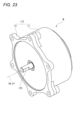
- FIG. 25 and 26 show cross sections of the actuator M at the same timing.
- the center E1 of the first eccentric hole 42 is located at the lowest end with respect to the rotation axis Pm
- FIG. 26 cross section taken along line B-B in FIG. 24
- the center E2 of the second eccentric hole 44 is located at the highest end with respect to the rotation axis Pm.
- the eccentricity E between the center E1 of the first eccentric hole 42 and the rotation axis Pm of the output shaft 170 is equal to the eccentricity E between the center E2 of the second eccentric hole 44 and the rotation axis Pm of the output shaft 170.
- the eccentricity E between each eccentric hole eccentric at intervals of 360°/n and the rotation axis Pm of the output shaft 170 is constant.
- the first and second internal gears 31 and 32 are rotatably arranged inside the first and second eccentric holes 42 and 44 via the bearings 33 and 34.
- the bearings 33 and 34 are positioned in the axial direction by the partition wall 43, and are arranged opposite each other with the partition wall 43 in between.
- the first and second internal gears 31 and 32 have the same tooth shape, are annular, and have multiple internal teeth 31a and 32a on their inner circumferences.
- the number of teeth of the internal teeth 31a and 32a of the first and second internal gears 31 and 32 is set to be greater than the number of teeth of the external teeth 27a of the external gear 27. In other words, the number of teeth of the external teeth 27a of the external gear 27 is less than the number of teeth of the internal teeth 31a and 32a of the first and second internal gears 31 and 32.
- the first internal gear 31 and the second internal gear 32 are each connected to the rotor 22 by a connecting mechanism 35 described below so as to be able to eccentrically swing, and are disposed eccentrically with respect to the external gear 27, with a portion meshing with the external gear 27.
- the external gear 27 may be formed integrally with the output shaft 170 and separately, with the external gear meshing with the first internal gear 31 and the external gear meshing with the second internal gear 32.
- each external gear has the same tooth profile shape and the same number of teeth.
- the connecting mechanism 35 connects the first internal gear 31 and the second internal gear 32 to each other in an eccentric state in the opposite phase direction of 180° by a plurality of connecting pins 36 that pass through a plurality of holes 31b, 31c, 32b, 32c formed in the first internal gear 31 and the second internal gear 32.
- the n internal gears are connected in an eccentric state at intervals of 360°/n.
- the first internal gear 31 and the second internal gear 32 are respectively provided with small holes 31b, 32b and large holes 31c, 32c of different diameters.
- the small holes 31b, 32b and the large holes 31c, 32c are alternately arranged, but the arrangement of the small holes 31b, 32b and the large holes 31c, 32c is not limited to this.
- the actuator case 173 is formed with pin receiving holes 173a and 173b in which the connecting pin 36 is inscribed, allowing the eccentric motion and rolling of the connecting pin 36.
- the connecting pin 36 is arranged in the circumferential direction, with the connecting pin 36 passing through the large hole 31c of the first internal gear 31 and the small hole 32b of the second internal gear 32, and the connecting pin 36 passing through the small hole 31b of the first internal gear 31 and the large hole 32c of the second internal gear 32.
- the first internal gear 31 oscillates as the center E1 of the first eccentric hole 42 revolves around the rotation axis Pm of the output shaft 170 by an eccentric amount E in association with the rotation of the rotor 22
- the second internal gear 32 oscillates as the center E2 of the second eccentric hole 44 revolves around the rotation axis Pm of the output shaft 170 by an eccentric amount E in association with the rotation of the rotor 22, so that the first internal gear 31 and the second internal gear 32 are eccentric in the opposite phase direction of 180°.
- the eccentricity is at intervals of 360°/n.
- the rotational input from the rotor 22 is converted into eccentric oscillation of the first internal gear 31 and the second internal gear 32 with a predetermined eccentricity amount E, and the output shaft 170 is rotated at a reduced speed by the meshing of the first internal gear 31 and the second internal gear 32 with the external gear 27.
- the actuator M is a direct-coupled motor in which the rotor 22 of the motor 171 housed in the actuator case 173 rotates integrally with the eccentric sleeve 40, which is the input member of the internal planetary gear mechanism 30.
- this is not limited to the direct-coupled motor, and the eccentric sleeve 40 may be rotationally driven by a transmission mechanism including gears, rollers, pulleys, etc.
- FIG. 1 For example, FIG.
- FIG. 27 shows an example in which a small motor 174 is housed in the actuator case 173, and the eccentric sleeve 40A is rotationally driven by meshing an output gear 175 provided on an output shaft connected to the rotor of the motor 174 with an input gear 41 formed on the outer circumferential surface of the eccentric sleeve 40A.
- the rotation axis P8 of the motor 174 and the output gear 175 are arranged to extend in a direction parallel to the rotation axis Pm of the output shaft 170.
- a larger reduction ratio can be obtained by the reduction caused by the meshing of the output gear 175 and the input gear 41, and the reduction between the first internal gear 31 and the second internal gear 32 and the external gear 27.
- this reduction method fixes the phase of the inner diameter of the eccentric female gear (sleeve 40) on the input side, and the male gear (external gear 27) at the center of the shaft is the output side, but it is the same even if the male gear on the input side is eccentric, the phase is fixed, and the female gear at the center of the shaft is the output side, that is, if the inner and outer diameter arrangement is reversed.
- the actuator M can be used as a drive device in a variety of devices, not just the electric prosthetic leg 1. For example, it can be ideally used as a drive device for reclining a vehicle seat.
- a prosthetic leg device (electric prosthetic leg) applied to a knee joint is exemplified as one embodiment of a coupling device in which the disconnecting device of the present invention is used, but the present invention is not limited to this, and may also be a prosthetic limb device (electric prosthetic limb) applied to an elbow joint, and the subject of the attachment may be an animal other than a human, or may be a robot.
- the below-knee member 110 of the above embodiment becomes the distal side of the subject of attachment relative to the above-knee member 120, i.e., the forearm.
- the expansion/contraction device is A drive device (actuator M) and a power transmission unit (transmission T) that transmits power of the drive device,
- the power transmission unit includes: a first power transmission path (first speed change mechanism T1) that transmits the power at a first speed change ratio; a second power transmission path (second speed change mechanism T2) that transmits the power at a second speed change ratio different from the first speed change ratio,
- the expansion/contraction device is a first interrupting mechanism (first interrupting mechanism 210) that switches between interruption and connection of power in the first power transmission path; a second interrupt
- the connecting part can be extended and bent via the power transmission part that transmits the power of the drive unit.
- the power transmission part has two power transmission paths with different gear ratios, the operating speed of extension and bending at the connecting part and the generated power can be switched.
- the coupling device can be made smaller. Note that the concept of oscillation includes eccentric movement (eccentric oscillation) and includes the behavior of eccentric movement inside the eccentric hole.
- the rotation of the first rotating body can be input from the rotating element to the internal planetary gear mechanism, and the rotation, whose speed is changed at the meshing portion between the internal gear and the external gear, can be output from the external gear to the second rotating body.
- the internal planetary gear mechanism is The gears include a plurality of the internal gears, and one of the external gears meshing with the plurality of the internal gears or a plurality of the external gears meshing with the plurality of the internal gears, a coupling device in which, when the number of the multiple internal gears and the multiple eccentric holes in which the internal gears are housed is n (n is an integer of 2 or more), the multiple eccentric holes are arranged so that a rotational phase difference between the multiple internal gears is 360°/n.
- the internal gear can be appropriately positioned.
- a coupling device according to (4) or (5), a coupling device in which the multiple internal gears are connected by a multiple connecting members (connecting pins 36) inserted into a multiple through holes (small holes 31 b, 32 b, large holes 31 c, 32 c) formed in each of the multiple internal gears, so that the rotational phase difference between the multiple internal gears is 360°/n.
- the rotational phase difference between multiple internal gears can be appropriately controlled simply by connecting them with multiple connecting members.
- the rotational phase difference between the internal gears can be appropriately controlled simply by connecting them with multiple connecting members.
- a coupling device according to any one of (1) to (7), The coupling device, wherein the rotating element has a gear (input gear 41) formed on its outer circumferential surface, to which the power of the drive unit is input.
- the drive unit is a rotary power source (motor 174) including a rotor
- the first rotating body is the rotor or a rotating body (output gear 175) that rotates integrally with the rotor
- a coupling device wherein the rotational power source and the rotational axis (rotational axis P8) of the first rotating body are arranged to extend in a direction parallel to the rotational axis (rotational axis Pm) of the second rotating body.
- the drive unit is a rotational power source (motor 171) including a rotor (rotor 22), the first rotating body is the rotor or a rotating body that rotates integrally with the rotor, A coupling device, wherein the rotational axis (rotational axis P7) of the rotational power source and the first rotating body are arranged on the same line as the rotational axis (rotational axis Pm) of the second rotating body.
- the coupling device can be made smaller.
- a drive device including a drive unit (motors 171, 174), a speed change unit (reduction unit 172) that is provided so as to be capable of transmitting power to the drive unit, and a housing member (actuator case 173) that houses the drive unit and the speed change unit
- the transmission unit includes: a first rotating body (rotor 22, output gear 175) and a second rotating body (output shaft 170) rotatably supported by the housing member; an internal planetary gear mechanism (internal planetary gear mechanism 30) disposed on a power transmission path of the first rotating body and the second rotating body;
- the internal planetary gear mechanism is annular internal gears (first internal gear 31, second internal gear 32) having internal teeth (internal teeth 31a, 32a) on their inner periphery; an external gear (external gear 27) having external teeth (external teeth 27a) on an outer periphery thereof, the external gear having a smaller number of teeth than the internal teeth, the external gear being disposed inside the internal gear and meshing with the internal gear
Landscapes
- Engineering & Computer Science (AREA)
- General Engineering & Computer Science (AREA)
- Mechanical Engineering (AREA)
- Prostheses (AREA)
Priority Applications (1)
| Application Number | Priority Date | Filing Date | Title |
|---|---|---|---|
| JP2025511204A JPWO2024204613A1 (https=) | 2023-03-31 | 2024-03-28 |
Applications Claiming Priority (2)
| Application Number | Priority Date | Filing Date | Title |
|---|---|---|---|
| JP2023-058081 | 2023-03-31 | ||
| JP2023058081 | 2023-03-31 |
Publications (1)
| Publication Number | Publication Date |
|---|---|
| WO2024204613A1 true WO2024204613A1 (ja) | 2024-10-03 |
Family
ID=92906734
Family Applications (1)
| Application Number | Title | Priority Date | Filing Date |
|---|---|---|---|
| PCT/JP2024/012824 Ceased WO2024204613A1 (ja) | 2023-03-31 | 2024-03-28 | 継手装置及び駆動装置 |
Country Status (2)
| Country | Link |
|---|---|
| JP (1) | JPWO2024204613A1 (https=) |
| WO (1) | WO2024204613A1 (https=) |
Citations (5)
| Publication number | Priority date | Publication date | Assignee | Title |
|---|---|---|---|---|
| JP2007056988A (ja) * | 2005-08-24 | 2007-03-08 | Ntn Corp | ハイポサイクロイド歯車減速装置 |
| JP2017025979A (ja) * | 2015-07-17 | 2017-02-02 | 本田技研工業株式会社 | 揺動許容の連結機構及び内接式遊星歯車装置 |
| JP2021143722A (ja) * | 2020-03-12 | 2021-09-24 | Ntn株式会社 | 電動アクチュエータ |
| JP2022133999A (ja) * | 2021-03-02 | 2022-09-14 | 本田技研工業株式会社 | 継手装置 |
| WO2022260098A1 (ja) * | 2021-06-11 | 2022-12-15 | 本田技研工業株式会社 | 継手装置 |
-
2024
- 2024-03-28 JP JP2025511204A patent/JPWO2024204613A1/ja active Pending
- 2024-03-28 WO PCT/JP2024/012824 patent/WO2024204613A1/ja not_active Ceased
Patent Citations (5)
| Publication number | Priority date | Publication date | Assignee | Title |
|---|---|---|---|---|
| JP2007056988A (ja) * | 2005-08-24 | 2007-03-08 | Ntn Corp | ハイポサイクロイド歯車減速装置 |
| JP2017025979A (ja) * | 2015-07-17 | 2017-02-02 | 本田技研工業株式会社 | 揺動許容の連結機構及び内接式遊星歯車装置 |
| JP2021143722A (ja) * | 2020-03-12 | 2021-09-24 | Ntn株式会社 | 電動アクチュエータ |
| JP2022133999A (ja) * | 2021-03-02 | 2022-09-14 | 本田技研工業株式会社 | 継手装置 |
| WO2022260098A1 (ja) * | 2021-06-11 | 2022-12-15 | 本田技研工業株式会社 | 継手装置 |
Also Published As
| Publication number | Publication date |
|---|---|
| JPWO2024204613A1 (https=) | 2024-10-03 |
Similar Documents
| Publication | Publication Date | Title |
|---|---|---|
| JP7705855B2 (ja) | 継手装置 | |
| KR102786926B1 (ko) | 동력 전달 기기, 운동 보조 장치 및 그 제어 방법 | |
| JP5525751B2 (ja) | 歩行ロボット | |
| WO2021189677A1 (zh) | 仿生机器人并联驱动关节的肢体结构和仿生机器人 | |
| WO2022260098A1 (ja) | 継手装置 | |
| JP7497360B2 (ja) | 継手装置 | |
| JP7604682B2 (ja) | 動力伝達装置 | |
| WO2024204613A1 (ja) | 継手装置及び駆動装置 | |
| CN109464227A (zh) | 一种多自由度的假肢手臂关节 | |
| EP3823563B1 (en) | Wrist prosthesis | |
| WO2024135748A1 (ja) | 継手装置 | |
| JP4057864B2 (ja) | 歩行補助装置の減速機 | |
| WO2024204612A1 (ja) | 動力伝達装置及び継手装置 | |
| CN117341856A (zh) | 一种仿生机械腿 | |
| JP2004089376A (ja) | 歩行補助装置の減速機 | |
| JP7830109B2 (ja) | 断続装置 | |
| JP2024179347A (ja) | 動力伝達装置 | |
| JP7733982B2 (ja) | 継手装置 | |
| JP7851717B2 (ja) | 断続装置 | |
| JP7674857B2 (ja) | 継手装置 | |
| JP2023088641A (ja) | 動力伝達装置 | |
| KR102701413B1 (ko) | 감속기 일체형 구동모터 | |
| JP2007113701A (ja) | 関節用減速機 | |
| JP2024179342A (ja) | 断続装置 | |
| JP2023088643A (ja) | 動力伝達装置 |
Legal Events
| Date | Code | Title | Description |
|---|---|---|---|
| 121 | Ep: the epo has been informed by wipo that ep was designated in this application |
Ref document number: 24780712 Country of ref document: EP Kind code of ref document: A1 |
|
| ENP | Entry into the national phase |
Ref document number: 2025511204 Country of ref document: JP Kind code of ref document: A |
|
| WWE | Wipo information: entry into national phase |
Ref document number: 2025511204 Country of ref document: JP |
|
| NENP | Non-entry into the national phase |
Ref country code: DE |
|
| 122 | Ep: pct application non-entry in european phase |
Ref document number: 24780712 Country of ref document: EP Kind code of ref document: A1 |