EP3823563B1 - Wrist prosthesis - Google Patents
Wrist prosthesis Download PDFInfo
- Publication number
- EP3823563B1 EP3823563B1 EP19762212.9A EP19762212A EP3823563B1 EP 3823563 B1 EP3823563 B1 EP 3823563B1 EP 19762212 A EP19762212 A EP 19762212A EP 3823563 B1 EP3823563 B1 EP 3823563B1
- Authority
- EP
- European Patent Office
- Prior art keywords
- stage
- cycloidal
- input shaft
- elements
- ring gear
- Prior art date
- Legal status (The legal status is an assumption and is not a legal conclusion. Google has not performed a legal analysis and makes no representation as to the accuracy of the status listed.)
- Active
Links
- 210000000707 wrist Anatomy 0.000 title claims description 29
- 230000007246 mechanism Effects 0.000 claims description 25
- 230000009467 reduction Effects 0.000 claims description 23
- 230000033001 locomotion Effects 0.000 claims description 17
- 238000005096 rolling process Methods 0.000 claims description 8
- 230000002093 peripheral effect Effects 0.000 claims description 4
- 230000008878 coupling Effects 0.000 claims description 3
- 238000010168 coupling process Methods 0.000 claims description 3
- 238000005859 coupling reaction Methods 0.000 claims description 3
- 230000005540 biological transmission Effects 0.000 description 13
- 230000009471 action Effects 0.000 description 2
- 238000005452 bending Methods 0.000 description 2
- 230000008901 benefit Effects 0.000 description 2
- 239000011248 coating agent Substances 0.000 description 2
- 238000000576 coating method Methods 0.000 description 2
- 238000004519 manufacturing process Methods 0.000 description 2
- JOYRKODLDBILNP-UHFFFAOYSA-N Ethyl urethane Chemical compound CCOC(N)=O JOYRKODLDBILNP-UHFFFAOYSA-N 0.000 description 1
- 230000006735 deficit Effects 0.000 description 1
- 210000003414 extremity Anatomy 0.000 description 1
- 230000006872 improvement Effects 0.000 description 1
- 230000010354 integration Effects 0.000 description 1
- 239000000463 material Substances 0.000 description 1
- 230000013011 mating Effects 0.000 description 1
- 229920003023 plastic Polymers 0.000 description 1
- 238000007493 shaping process Methods 0.000 description 1
- 230000035939 shock Effects 0.000 description 1
- 210000000323 shoulder joint Anatomy 0.000 description 1
- 239000007787 solid Substances 0.000 description 1
- 230000003068 static effect Effects 0.000 description 1
Images


Classifications
-
- A—HUMAN NECESSITIES
- A61—MEDICAL OR VETERINARY SCIENCE; HYGIENE
- A61F—FILTERS IMPLANTABLE INTO BLOOD VESSELS; PROSTHESES; DEVICES PROVIDING PATENCY TO, OR PREVENTING COLLAPSING OF, TUBULAR STRUCTURES OF THE BODY, e.g. STENTS; ORTHOPAEDIC, NURSING OR CONTRACEPTIVE DEVICES; FOMENTATION; TREATMENT OR PROTECTION OF EYES OR EARS; BANDAGES, DRESSINGS OR ABSORBENT PADS; FIRST-AID KITS
- A61F2/00—Filters implantable into blood vessels; Prostheses, i.e. artificial substitutes or replacements for parts of the body; Appliances for connecting them with the body; Devices providing patency to, or preventing collapsing of, tubular structures of the body, e.g. stents
- A61F2/50—Prostheses not implantable in the body
- A61F2/54—Artificial arms or hands or parts thereof
- A61F2/58—Elbows; Wrists ; Other joints; Hands
- A61F2/583—Hands; Wrist joints
- A61F2/585—Wrist joints
-
- A—HUMAN NECESSITIES
- A61—MEDICAL OR VETERINARY SCIENCE; HYGIENE
- A61F—FILTERS IMPLANTABLE INTO BLOOD VESSELS; PROSTHESES; DEVICES PROVIDING PATENCY TO, OR PREVENTING COLLAPSING OF, TUBULAR STRUCTURES OF THE BODY, e.g. STENTS; ORTHOPAEDIC, NURSING OR CONTRACEPTIVE DEVICES; FOMENTATION; TREATMENT OR PROTECTION OF EYES OR EARS; BANDAGES, DRESSINGS OR ABSORBENT PADS; FIRST-AID KITS
- A61F2/00—Filters implantable into blood vessels; Prostheses, i.e. artificial substitutes or replacements for parts of the body; Appliances for connecting them with the body; Devices providing patency to, or preventing collapsing of, tubular structures of the body, e.g. stents
- A61F2/50—Prostheses not implantable in the body
- A61F2/68—Operating or control means
-
- F—MECHANICAL ENGINEERING; LIGHTING; HEATING; WEAPONS; BLASTING
- F16—ENGINEERING ELEMENTS AND UNITS; GENERAL MEASURES FOR PRODUCING AND MAINTAINING EFFECTIVE FUNCTIONING OF MACHINES OR INSTALLATIONS; THERMAL INSULATION IN GENERAL
- F16H—GEARING
- F16H1/00—Toothed gearings for conveying rotary motion
- F16H1/28—Toothed gearings for conveying rotary motion with gears having orbital motion
- F16H1/32—Toothed gearings for conveying rotary motion with gears having orbital motion in which the central axis of the gearing lies inside the periphery of an orbital gear
-
- F—MECHANICAL ENGINEERING; LIGHTING; HEATING; WEAPONS; BLASTING
- F16—ENGINEERING ELEMENTS AND UNITS; GENERAL MEASURES FOR PRODUCING AND MAINTAINING EFFECTIVE FUNCTIONING OF MACHINES OR INSTALLATIONS; THERMAL INSULATION IN GENERAL
- F16H—GEARING
- F16H37/00—Combinations of mechanical gearings, not provided for in groups F16H1/00 - F16H35/00
- F16H37/02—Combinations of mechanical gearings, not provided for in groups F16H1/00 - F16H35/00 comprising essentially only toothed or friction gearings
- F16H37/06—Combinations of mechanical gearings, not provided for in groups F16H1/00 - F16H35/00 comprising essentially only toothed or friction gearings with a plurality of driving or driven shafts; with arrangements for dividing torque between two or more intermediate shafts
- F16H37/065—Combinations of mechanical gearings, not provided for in groups F16H1/00 - F16H35/00 comprising essentially only toothed or friction gearings with a plurality of driving or driven shafts; with arrangements for dividing torque between two or more intermediate shafts with a plurality of driving or driven shafts
-
- A—HUMAN NECESSITIES
- A61—MEDICAL OR VETERINARY SCIENCE; HYGIENE
- A61F—FILTERS IMPLANTABLE INTO BLOOD VESSELS; PROSTHESES; DEVICES PROVIDING PATENCY TO, OR PREVENTING COLLAPSING OF, TUBULAR STRUCTURES OF THE BODY, e.g. STENTS; ORTHOPAEDIC, NURSING OR CONTRACEPTIVE DEVICES; FOMENTATION; TREATMENT OR PROTECTION OF EYES OR EARS; BANDAGES, DRESSINGS OR ABSORBENT PADS; FIRST-AID KITS
- A61F2/00—Filters implantable into blood vessels; Prostheses, i.e. artificial substitutes or replacements for parts of the body; Appliances for connecting them with the body; Devices providing patency to, or preventing collapsing of, tubular structures of the body, e.g. stents
- A61F2/50—Prostheses not implantable in the body
- A61F2002/5081—Additional features
- A61F2002/5083—Additional features modular
-
- A—HUMAN NECESSITIES
- A61—MEDICAL OR VETERINARY SCIENCE; HYGIENE
- A61F—FILTERS IMPLANTABLE INTO BLOOD VESSELS; PROSTHESES; DEVICES PROVIDING PATENCY TO, OR PREVENTING COLLAPSING OF, TUBULAR STRUCTURES OF THE BODY, e.g. STENTS; ORTHOPAEDIC, NURSING OR CONTRACEPTIVE DEVICES; FOMENTATION; TREATMENT OR PROTECTION OF EYES OR EARS; BANDAGES, DRESSINGS OR ABSORBENT PADS; FIRST-AID KITS
- A61F2/00—Filters implantable into blood vessels; Prostheses, i.e. artificial substitutes or replacements for parts of the body; Appliances for connecting them with the body; Devices providing patency to, or preventing collapsing of, tubular structures of the body, e.g. stents
- A61F2/50—Prostheses not implantable in the body
- A61F2/68—Operating or control means
- A61F2002/6836—Gears specially adapted therefor, e.g. reduction gears
-
- A—HUMAN NECESSITIES
- A61—MEDICAL OR VETERINARY SCIENCE; HYGIENE
- A61F—FILTERS IMPLANTABLE INTO BLOOD VESSELS; PROSTHESES; DEVICES PROVIDING PATENCY TO, OR PREVENTING COLLAPSING OF, TUBULAR STRUCTURES OF THE BODY, e.g. STENTS; ORTHOPAEDIC, NURSING OR CONTRACEPTIVE DEVICES; FOMENTATION; TREATMENT OR PROTECTION OF EYES OR EARS; BANDAGES, DRESSINGS OR ABSORBENT PADS; FIRST-AID KITS
- A61F2/00—Filters implantable into blood vessels; Prostheses, i.e. artificial substitutes or replacements for parts of the body; Appliances for connecting them with the body; Devices providing patency to, or preventing collapsing of, tubular structures of the body, e.g. stents
- A61F2/50—Prostheses not implantable in the body
- A61F2/68—Operating or control means
- A61F2/70—Operating or control means electrical
- A61F2002/701—Operating or control means electrical operated by electrically controlled means, e.g. solenoids or torque motors
-
- F—MECHANICAL ENGINEERING; LIGHTING; HEATING; WEAPONS; BLASTING
- F16—ENGINEERING ELEMENTS AND UNITS; GENERAL MEASURES FOR PRODUCING AND MAINTAINING EFFECTIVE FUNCTIONING OF MACHINES OR INSTALLATIONS; THERMAL INSULATION IN GENERAL
- F16H—GEARING
- F16H1/00—Toothed gearings for conveying rotary motion
- F16H1/28—Toothed gearings for conveying rotary motion with gears having orbital motion
- F16H1/32—Toothed gearings for conveying rotary motion with gears having orbital motion in which the central axis of the gearing lies inside the periphery of an orbital gear
- F16H2001/325—Toothed gearings for conveying rotary motion with gears having orbital motion in which the central axis of the gearing lies inside the periphery of an orbital gear comprising a carrier with pins guiding at least one orbital gear with circular holes
-
- F—MECHANICAL ENGINEERING; LIGHTING; HEATING; WEAPONS; BLASTING
- F16—ENGINEERING ELEMENTS AND UNITS; GENERAL MEASURES FOR PRODUCING AND MAINTAINING EFFECTIVE FUNCTIONING OF MACHINES OR INSTALLATIONS; THERMAL INSULATION IN GENERAL
- F16H—GEARING
- F16H2702/00—Combinations of two or more transmissions
- F16H2702/02—Mechanical transmissions with planetary gearing combined with one or more other mechanical transmissions
Definitions
- the present invention relates to a prosthetic wrist unit comprising a drive motor, suitable for being kinematically interposed between the distal end of an arm prosthesis and a prosthetic terminal device, for positioning the terminal device at desired orientations with respect to the arm prosthesis.
- the human wrist significantly contributes to hand mobility and handling skills in healthy individuals.
- the role of the wrist in grasping is to place the hand in the appropriate orientation to allow gripping and handling to be performed. Losing the wrist functionality involves a significant impairment for that person.
- a prosthetic wrist is the result of compromises between the functionality and practicality of the device. This means that the wrist must be light and compact enough to be carried to the distal end of the arm, regardless of the level of loss. It must also be easy to control in order to allow the bearer to use the device easily, without having to focus on the device and how it should be controlled. Any prosthetic wrist unit increases the mass and cost of the entire limb prosthesis, and there is a perceived lack of improvement in functionality once it has been provided to the user. If the terminal prosthetic device fails to be easily positioned, then it is likely that the user will prefer not to use the prosthetic wrist unit.
- the mechanism in order to be used by patients, the mechanism must meet high standards of strength and silence and provide the irreversibility of the system if the user tries to turn the wrist with the engine switched off.
- the active prosthetic wrists which can reach driving torques similar to the healthy human wrist can be quite heavy or long.
- Document EP3102157A1 describes an arm prosthesis comprising a motorized prosthetic wrist unit comprising a planetary gear transmission, a clutch and a cycloidal transmission. However, the entire prosthesis is heavy and complex.
- the present invention aims at the above-described objectives and at overcoming the drawbacks of the currently known devices with a prosthetic wrist unit as described at the beginning, which further comprises a reduction mechanism formed by a first epicycloidal reduction stage and a second cycloidal reduction stage, connected to each other, wherein the first stage comprises a central wheel connected to the motor shaft, one or more satellite wheels rotatably placed around their own axis on a planet carrier, and a fixed outer ring gear, the satellite wheels being in peripheral contact with the central wheel and with the outer ring gear, and the planet carrier being connected to the second stage, and wherein the central wheel, the satellite wheels and the outer ring gear have smooth mutually engaging surfaces, in such a way that the rolling of the satellite wheels on the outer ring gear is caused by the friction forces generated by radial interference between the central wheel and the satellite wheels and the outer ring gear.
- transmission mechanisms generally for transferring a motion between an input shaft or element and an output shaft or element through a gear, in various applications, especially for the variation ( i.e., multiplication or reduction) of the rotation speed and the driving torque between the input shaft and the output shaft.
- the gears are gear trains which include typically toothed or lobed members rotatable about respective axes of rotation and cooperating with each other so as to allow the transfer of a rotational motion.
- the aforementioned gears define:
- the epicycloidal transmission mechanisms comprise a gear which results in a planetary gear train in which a point, belonging to the pitch circle defined by a satellite member suitable for rolling externally in engagement with the pitch circle, defined in turn by a planetary member, operationally traces a trajectory of an epicycloid.
- the epicycloidal transmission mechanisms comprise a plurality of satellite wheels mounted with freedom of rotation on a supporting element referred to as a planet carrier, and a central wheel or sun cooperating externally with the satellite wheels; all this is positioned within a ring, also referred to as a ring gear, bearing a typically toothed or lobed internal engagement surface, with which the satellite wheels cooperate externally.
- Such epicycloidal transmission mechanisms are manufactured with traditional gears, in particular with the tooth profile being the involute of a circle.
- Such epicycloidal transmission mechanisms have motion reversibility, high precision, reduced mechanical backlash.
- the cycloidal transmission mechanisms comprise a gear which results in a planetary gear train in which a point, belonging to the pitch circle defined by a toothed or lobed satellite member suitable for rolling internally by eccentric orbital motion in engagement with the pitch circle, defined in turn by a toothed or lobed outer ring gear, operationally traces a trajectory of a hypocycloid.
- the cycloidal transmission mechanisms generally have a compact structure, in which the planetary and satellite toothing or lobing have large and solid teeth or lobes, and the reduction ratio equals 1:n, where 1 is an eccentric rotation turn and n is the number of teeth or lobes of the rotating part.
- the two-stage configuration of the present invention is characterized by high transmissible torque values, combined with high silence and compactness; the first stage is suitable for low driving torques and high speeds, whereas the second is particularly suitable for being used with high driving torques and low speeds. Furthermore, a characteristic intrinsic to the second cycloidal stage is to ensure a certain degree of irreversibility of the motion, in this case desired, to allow to save the electric power coming from the batteries in the event of continuous static external loads.
- the first stage is placed proximally and is connected to a motor shaft, and the second stage is placed distally and is connected to a terminal device fastening element.
- the two mechanisms altogether allow for such a compactness as to fit into the tight dimensions of a wrist prosthesis, and to maintain high structural strength, allowing high mechanical shocks to be absorbed.
- the cycloidal mechanism is generally used on machine tools and anthropomorphic industrial robots, such as in shoulder joints, i.e., in applications where a great structural rigidity is required, and weight is not a problem.
- such mechanism has been adapted to a small and light version, applicable to reduced diameters specific for the anthropometric size of the wrist, allowing a high reduction in a small space, with high relative transmissible torque.
- the balancing and lightening of the two systems allow the creation of an overall mechanism with the necessary performance requirements.
- the satellite wheels rotate on the fixed outer ring gear under the action of the central wheel, and transmit the motion to the planet carrier and, accordingly, to the second stage.
- the central wheel, the satellite wheels and the outer ring gear have smooth mutually engaging surfaces, in such a way that the rolling of the satellite wheels on the ring gear is caused by the friction forces generated by radial interference between the central wheel and the satellite wheels and between the satellite wheels and the outer ring gear, the central wheel can be made up of a bush with a smooth coating surface, keyed onto the motor shaft.
- the satellites thus perform a rolling, without sliding, on the fixed outer ring gear due to friction forces. Therefore, no teeth are used for this satellite planetary stage application, as in the usual known applications, but it is preferred to transmit the forces through surface friction, in order to sacrifice part of the transmissible torque and benefit in terms of silence and system costs.
- the satellite wheels are made up of ball bearings or radial ball bearings with the outer diameter coated in urethane.
- an internally toothed ring gear and toothed satellite wheels may be provided as an alternative.
- the central wheel is made up of a toothed pinion.
- the planet carrier is provided with pins for engaging the satellite wheels, the satellite wheels being provided with seats for housing the engagement pins; the housing seats are larger than the engagement pins.
- a dimensional gap is thereby formed on the diameter of the engagement pins with respect to the inner diameter of the housing seats provided in the satellite wheels: this is to allow the satellite wheels to adapt automatically to the real size and tolerances of the central wheel and the ring gear, fixing the dimensional / geometric manufacturing mistakes and avoiding to produce hyperstatic mechanical systems which would inevitably lead to breaks.
- the second stage comprises an input shaft connected to the first stage and provided with one or more eccentric portions with respect to its own axis, a fixed outer cam defining an inner lobing and centred around the axis of the input shaft, and one or more cycloidal elements.
- the cycloidal elements are engaged on the eccentric portions of the input shaft so as to be rotatable with eccentric orbital motion with respect to the axis of the input shaft and are provided with a satellite outer lobing meshing peripherally with said inner lobing.
- the cycloidal elements have a plurality of holes in which a corresponding plurality of protrusions of an output rotating element engages, the output rotating element being connected to the terminal device fastening element.
- the cycloidal elements by maintaining the contact on the outer cam, reduce the motion as they have a lower number of lobes than the cam seats made up of the compartments or recesses present in the inner lobing of the outer cam; after a complete revolution, each cycloidal element will have been left behind with respect to the outer cam by the arc of circle equal to the missing compartments, and the speed at which the disks lose ground with respect to the frame is output by the output element to reduce the incoming motion.
- the second stage comprises at least two cycloidal elements which are offset from each other with respect to the axis of the input shaft.
- the cycloidal elements may be arranged so as to show any phase difference.
- two cycloidal elements that are offset by 180° are provided, which, thanks to their operating symmetry, ensure the dynamic equilibrium of the system, so as to extend the lifetime of the mechanism and its components, decrease noise and vibrations.
- the dynamic equilibrium is due to the distribution of the contact forces between the cycloidal elements and the outer cam which, due to the 180° offset between the cycloidal elements, are always equal and opposite in any operating point, thus avoiding the generation of unwanted second order vibrations.
- additional cycloidal elements may be added, suitably phased with each other. This addition of cycloidal elements allows to transmit a greater output driving torque, as well as to better withstand external impulsive loads, although, on the other hand, increases the weight and length of the prosthetic unit, not to mention a difficulty of assembly.
- the outer cam is formed by a plurality of dowels parallel to each other arranged to form a crown around the axis of the input shaft and angularly equally spaced apart so as to form cam seats for engaging with the outer lobing of the cycloidal elements.
- the output rotating element comprises two separate parts, a first part of which is placed proximally with respect to the cycloidal elements and a second part is placed distally with respect to the cycloidal elements, the first part and the second part being connected to each other by means of the said protrusions.
- the planet carrier of the first stage is integrally engaged with the input shaft of the second stage by shape coupling.
- This configuration ensures high torque transmission with little available surface and high ease of assembly and disassembly.
- the second stage has a recess in the central area of the proximal end surface, the recess in the assembled condition housing at least part of the first stage.
- the first and second stages are housed in an outer frame, one or more ball bearings being provided interposed between the output rotating element and the outer frame.
- the output element is shaped so as to allow integration with the prosthetic terminal device to be connected downstream.
- the output element can be shaped so as to integrally complete the terminal device fastening element.
- the output element is fixed to the terminal device fastening element.
- the active wrist prosthesis object of the present invention is able to perform, in the presence of a motor, the human pronation and supination movements, not exceeding the overall dimensions imposed by human anthropomorphism and by the socket of amputated patients, all this respecting the values of torque and speed of a natural human wrist.
- the prosthetic unit is active and therefore comprises a drive motor 3.
- the motor 3 can be of any currently known type, preferably it is an electric motor, such as a commercial brushless motor.
- the motor 3 is provided with an output motor shaft 30, which transmits the motion to the downstream kinematic chains.
- the prosthetic unit is suitable for being kinematically interposed between the distal end of an arm prosthesis and a prosthetic terminal device, such as a hand prosthesis, for positioning the terminal device at desired orientations with respect to the arm prosthesis.
- the motor 3 is positioned at the proximal end 6 of the prosthetic unit.
- a terminal device fastening element 4 is positioned at the distal end 7 of the prosthetic unit, i.e., the end for the connection with the prosthetic terminal device.
- the terminal device fastening element 4 is rotatably actuated by the motor 3 by means of a reduction mechanism, housed within an outer frame 5 made up of a cylindrical casing.
- the reduction mechanism comprises a first epicycloidal reduction stage 1 and a second cycloidal reduction stage 2, connected to each other.
- the first stage 1 is placed proximally and is connected to the motor shaft 30, and is thus suitable for low driving torques and high speeds;
- the second stage 2 is placed distally and is connected to the terminal device fastening element 4 and is suitable for being used for high driving torques and low speeds.
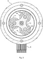
- the first stage 1, shown in Figure 2 comprises a central wheel 10 connected to the motor shaft 30, in particular keyed or forced onto the motor shaft 30.
- the central wheel 10 is made up of a bush with a rated outer diameter of 2.95 mm keyed onto the motor shaft 30 and, therefore, has a smooth coating surface.
- the first epicycloidal stage 1 further comprises three satellite wheels 11 rotatably placed around its own axis on a planet carrier 12, angularly equally spaced apart from each other by 120°.
- the satellite wheels 11 are placed in peripheral contact with the central wheel 10 and have smooth engaging surfaces.
- the planet carrier 12 is provided with engagement pins 122 of the satellite wheels 11 suitable for engaging in corresponding housing seats 121 provided in the satellite wheels 11.
- the housing seats 121 have a diameter greater than the engagement pins 122 so as to create a dimensional gap to allow the satellite wheels 11 to adapt automatically to the real size and tolerances of the central wheel 10 and of the fixed ring gear 13.
- the satellite wheels 11 are preferably made up of ball bearings.
- the housing seats 122 are made up of the central holes of the ball bearings.
- the satellite wheels 11 have a rated outer diameter of 9 mm and rotate about their axis positioned at a diameter of 12 mm on the planet carrier 12.
- the first stage 1 also comprises a fixed outer ring gear 13.
- the first stage 1 is shaped in such a way that the satellite wheels 11 are in peripheral contact simultaneously with the central wheel 10 and the outer ring gear 13.
- the outer ring gear 13 has a rated inner diameter of 20.8 mm.
- the outer ring gear 13, too, has the engaging surface, i.e., the surface facing inwards, being smooth.
- the first stage 1 is therefore a roller-based epicycloidal reduction stage, in which the central wheel 10, the satellite wheels 11 and the outer ring gear 13 have smooth mutually engaging surfaces, so that the rolling is caused by the friction forces generated by radial interference between the components.
- the entire first stage 1 is implemented through an appropriate design effort on compacting.
- the planet carrier 12 represents the output of the first stage 1, being connected to the second stage 2. Therefore, in the first stage 1, the satellite wheels 11 rotate on the fixed outer ring gear 13 under the action of the central wheel 10 and transmit the motion to the planet carrier 12 and, accordingly, to the second stage 2.
- the planet carrier 12 consists of two distinct parts joined together by means of the engagement pins 122.
- the planet carrier 12 may be provided in a single piece and with engagement pins 122 fixed in a cantilevered manner.
- the first stage 1 is an epicycloidal mechanism with a reduction ratio of about 8:1.
- the second cycloidal stage 2 shown in Figure 3 , comprises an input shaft 20 connected to the first stage 1.
- the input shaft 20 is integrally engaged with the planet carrier 12 of the first stage 1 by shape coupling.
- the input shaft 20 is provided with two eccentric portions with respect to its own axis, a first eccentric portion 201 of which being placed proximally and a second eccentric portion 202 being placed distally and offset by 180 °.
- the two eccentric portions 201 and 202 are placed adjacent to each other for the sake of compactness, but may also be provided spaced apart.
- the second stage 2 further comprises a fixed outer cam 23 defining an inner lobing and centred around the axis of the input shaft 20.
- the second stage 2 further comprises two cycloidal elements 21 and 22 in the form of disks.
- a first cycloidal element 21 is engaged on the first eccentric portion 201 of the input shaft 20 by means of a ball bearing 211
- a second cycloidal element 22 is engaged on the second eccentric portion 202 of the input shaft 20 by means of a ball bearing 221, and they are therefore both rotatable by eccentric orbital motion with respect to the axis of the input shaft 20.
- the cycloidal elements 21 and 22 are each provided with a satellite outer lobing meshing peripherally with the inner lobing of the outer cam 23.
- the cycloidal elements 21 and 22 are offset from each other by 180° with respect to the axis of the input shaft 20, the two eccentric portions 201 and 202 on which they are fixed being offset from each other by a corresponding angle.
- the outer cam 23 is formed by a plurality of dowels 230, e.g., of a commercial type, parallel to each other, arranged to form a crown around the axis of the input shaft 20 and angularly equally spaced apart from each other.
- the dowels 230 are held in place by a supporting fixed outer ring gear 232, integral with the outer frame 5. Compartments or recesses forming cam seats 231 for engaging with the outer lobing of the cycloidal elements 21 and 22 are formed between consecutive dowels 230.
- the supporting fixed outer ring gear 232 is divided into two parts and is assembled during assembly. Thirty-four dowels 230 are mounted on the supporting fixed outer ring gear 232 and, accordingly, thirty-four cam seats 231 are created between the dowels 230.
- the cycloidal elements 21 and 22, in the preferred exemplary embodiment shown in the figure, have a pitch diameter of 24.75 mm and have 33 lobes and 33 compartments, i.e., one less than those of the fixed outer cam 23, to achieve the desired reduction.
- the two cycloidal elements 21 and 22, therefore, keeping the contact on the dowels 230 fixed in the supporting outer ring gear 232, reduce the motion as they have one less lobe than the cam seats 231 existing between the dowels 230 of the supporting outer ring gear 232; after a complete revolution, each cycloidal element will have been left behind with respect to the supporting fixed outer ring gear 232 of the arc of circle equal to the missing cam seat 231, and the speed at which the two cycloidal elements 21 and 22 lose ground with respect to the outer frame 5 is output by the output rotating element 24 to reduce the incoming motion impressed by the motor 3.
- the two cycloidal elements 21 and 22 have a plurality of holes 210 and 220 placed in a mating position in an assembled condition.
- a corresponding plurality of protrusions 242 of an output rotating element 24 engages in the holes 210 and 220, being such as to constantly achieve contact during the envelope motion of the cycloidal elements 21 and 22 during their eccentric rotation.
- the output rotating element 24 is connected to the terminal device fastening element 4.
- the output rotating element 24 is rotatably engaged with the outer frame 5 by means of two ball bearings 50 and with the input shaft 20 by means of two ball bearings 26.
- the output rotating element 24 comprises two separate parts, a first part 240 of which is placed proximally with respect to the cycloidal elements 21 and 22, and a second part 241 is placed distally with respect to the cycloidal elements 20 and 21.
- the protrusions 242 consist of six pins 243 which connect the first part 240 and the second part 241 to each other, each pin 243 being covered by a bush 244 with reduced rolling resistance friction.
- Such bushes 244 have a diameter of 4.5 mm, whereas the holes 210 and 220 in the cycloidal elements 21 and 22 have a diameter of 5.04 mm, thereby considering the 0.26 mm eccentricity.
- the second stage 2 is a cycloidal mechanism with a reduction ratio of 33:1.
- the reduction mechanism of the prosthetic unit has a total reduction ratio of about 264:1.
- the second stage 2 has a recess 25 in the central area of the proximal end surface, in particular obtained by suitably shaping the first part 240 of the output rotating element 24.
- Such recess 25 in the assembled condition of the first stage 1 and of the second stage 2 houses part of the first stage 1, in particular part of the planet carrier 12.
- Figures 4 and 5 show two different axonometric views of the assembled prosthetic unit, wherein the cylindrical frame 5 surrounding the first stage 1 and the second stage 2 is visible.
- the terminal device fastening element 4 has an end nut 40 provided with engagement teeth suitable for connection with the terminal device.
- the terminal device fastening element 4 is fixed to the second part 241 of the output rotating element 24 by means of through screws which engage with corresponding threaded seats provided in the pins 243, as shown in Figure 1 .
- the terminal device fastening element 4 also has slots 41 for the passage of control and supply electrical wires.
- the motor 3 is enclosed by a cover 31, which can be fixed to the frame 5 by means of screws.
- the cover 31 is provided with a plurality of electrical terminals 8 for connecting the motor 3 to a supply unit and / or a control unit, not shown in the figures.
- the reduction mechanism may comprise further reduction stages and may be varied to adapt the reduction required for other application cases.
- Weights may be optimized by using the so-called technopolymer materials.
Description
- The present invention relates to a prosthetic wrist unit comprising a drive motor, suitable for being kinematically interposed between the distal end of an arm prosthesis and a prosthetic terminal device, for positioning the terminal device at desired orientations with respect to the arm prosthesis.
- The human wrist significantly contributes to hand mobility and handling skills in healthy individuals. The role of the wrist in grasping is to place the hand in the appropriate orientation to allow gripping and handling to be performed. Losing the wrist functionality involves a significant impairment for that person.
- However, the prosthetic industry, as well as research, has often neglected the prosthetic wrists in favour of the development of terminal devices.
- The design of a prosthetic wrist is the result of compromises between the functionality and practicality of the device. This means that the wrist must be light and compact enough to be carried to the distal end of the arm, regardless of the level of loss. It must also be easy to control in order to allow the bearer to use the device easily, without having to focus on the device and how it should be controlled. Any prosthetic wrist unit increases the mass and cost of the entire limb prosthesis, and there is a perceived lack of improvement in functionality once it has been provided to the user. If the terminal prosthetic device fails to be easily positioned, then it is likely that the user will prefer not to use the prosthetic wrist unit.
- Nowadays, it is difficult to be able to realize an active wrist device which is compact enough to fit in the anthropometric dimensions and the socket of the patients.
- In addition to this, in order to be used by patients, the mechanism must meet high standards of strength and silence and provide the irreversibility of the system if the user tries to turn the wrist with the engine switched off.
- These requirements are not adequately met by the prosthetic wrist units known in the art.
- Most commercially available devices are passive, generally devices with 1 or 2 degrees of freedom, having only a few motorized active rotators available.
- Most prosthetic wrists with multiple degrees of freedom are mechanisms placed in series, which, although easy to design and manufacture, are more prone to excessive length.
- The active prosthetic wrists which can reach driving torques similar to the healthy human wrist can be quite heavy or long.
- Document
EP3102157A1 describes an arm prosthesis comprising a motorized prosthetic wrist unit comprising a planetary gear transmission, a clutch and a cycloidal transmission. However, the entire prosthesis is heavy and complex. - The relatively compact active prosthetic wrists have a very low driving torque. This compromise must be addressed in the development of more sophisticated wrist prostheses.
- Currently, there is thus an unaddressed need for an active wrist prosthesis meeting the high standards of compactness required and capable of ensuring the performance of a human wrist, silent operation and irreversibility of the system with the motor turned off.
- The present invention aims at the above-described objectives and at overcoming the drawbacks of the currently known devices with a prosthetic wrist unit as described at the beginning, which further comprises a reduction mechanism formed by a first epicycloidal reduction stage and a second cycloidal reduction stage, connected to each other, wherein the first stage comprises a central wheel connected to the motor shaft, one or more satellite wheels rotatably placed around their own axis on a planet carrier, and a fixed outer ring gear, the satellite wheels being in peripheral contact with the central wheel and with the outer ring gear, and the planet carrier being connected to the second stage, and wherein the central wheel, the satellite wheels and the outer ring gear have smooth mutually engaging surfaces, in such a way that the rolling of the satellite wheels on the outer ring gear is caused by the friction forces generated by radial interference between the central wheel and the satellite wheels and the outer ring gear.
- The use of transmission mechanisms is widely known, generally for transferring a motion between an input shaft or element and an output shaft or element through a gear, in various applications, especially for the variation (i.e., multiplication or reduction) of the rotation speed and the driving torque between the input shaft and the output shaft.
- More in detail, the gears are gear trains which include typically toothed or lobed members rotatable about respective axes of rotation and cooperating with each other so as to allow the transfer of a rotational motion.
- The aforementioned gears define:
- an ordinary gear train when they include a plurality of members in which the axes of rotation are operatively fixed, or
- a planetary gear train when they include at least one planetary member whose axis of rotation is operatively fixed and at least one other satellite member whose axis of rotation is operatively movable.
- Among the transmission mechanisms provided with a gear constituting a planetary gear train, epicycloidal transmission mechanisms and cycloidal (or hypocycloidal) transmission mechanisms are known.
- The epicycloidal transmission mechanisms comprise a gear which results in a planetary gear train in which a point, belonging to the pitch circle defined by a satellite member suitable for rolling externally in engagement with the pitch circle, defined in turn by a planetary member, operationally traces a trajectory of an epicycloid.
- Generally, the epicycloidal transmission mechanisms comprise a plurality of satellite wheels mounted with freedom of rotation on a supporting element referred to as a planet carrier, and a central wheel or sun cooperating externally with the satellite wheels; all this is positioned within a ring, also referred to as a ring gear, bearing a typically toothed or lobed internal engagement surface, with which the satellite wheels cooperate externally.
- Typically, such epicycloidal transmission mechanisms are manufactured with traditional gears, in particular with the tooth profile being the involute of a circle.
- Such epicycloidal transmission mechanisms have motion reversibility, high precision, reduced mechanical backlash.
- By contrast, the cycloidal transmission mechanisms comprise a gear which results in a planetary gear train in which a point, belonging to the pitch circle defined by a toothed or lobed satellite member suitable for rolling internally by eccentric orbital motion in engagement with the pitch circle, defined in turn by a toothed or lobed outer ring gear, operationally traces a trajectory of a hypocycloid.
- The cycloidal transmission mechanisms generally have a compact structure, in which the planetary and satellite toothing or lobing have large and solid teeth or lobes, and the reduction ratio equals 1:n, where 1 is an eccentric rotation turn and n is the number of teeth or lobes of the rotating part.
- The two-stage configuration of the present invention is characterized by high transmissible torque values, combined with high silence and compactness; the first stage is suitable for low driving torques and high speeds, whereas the second is particularly suitable for being used with high driving torques and low speeds. Furthermore, a characteristic intrinsic to the second cycloidal stage is to ensure a certain degree of irreversibility of the motion, in this case desired, to allow to save the electric power coming from the batteries in the event of continuous static external loads.
- In an exemplary embodiment, the first stage is placed proximally and is connected to a motor shaft, and the second stage is placed distally and is connected to a terminal device fastening element.
- Therefore, the two mechanisms altogether allow for such a compactness as to fit into the tight dimensions of a wrist prosthesis, and to maintain high structural strength, allowing high mechanical shocks to be absorbed.
- The cycloidal mechanism is generally used on machine tools and anthropomorphic industrial robots, such as in shoulder joints, i.e., in applications where a great structural rigidity is required, and weight is not a problem. In this case, such mechanism has been adapted to a small and light version, applicable to reduced diameters specific for the anthropometric size of the wrist, allowing a high reduction in a small space, with high relative transmissible torque.
- The balancing and lightening of the two systems allow the creation of an overall mechanism with the necessary performance requirements.
- In the first stage, the satellite wheels rotate on the fixed outer ring gear under the action of the central wheel, and transmit the motion to the planet carrier and, accordingly, to the second stage.
- Since the central wheel, the satellite wheels and the outer ring gear have smooth mutually engaging surfaces, in such a way that the rolling of the satellite wheels on the ring gear is caused by the friction forces generated by radial interference between the central wheel and the satellite wheels and between the satellite wheels and the outer ring gear, the central wheel can be made up of a bush with a smooth coating surface, keyed onto the motor shaft.
- The satellites thus perform a rolling, without sliding, on the fixed outer ring gear due to friction forces. Therefore, no teeth are used for this satellite planetary stage application, as in the usual known applications, but it is preferred to transmit the forces through surface friction, in order to sacrifice part of the transmissible torque and benefit in terms of silence and system costs.
- In an advantageous embodiment, the satellite wheels are made up of ball bearings or radial ball bearings with the outer diameter coated in urethane.
- However, an internally toothed ring gear and toothed satellite wheels may be provided as an alternative. In this case, the central wheel is made up of a toothed pinion.
- In a further exemplary embodiment, the planet carrier is provided with pins for engaging the satellite wheels, the satellite wheels being provided with seats for housing the engagement pins; the housing seats are larger than the engagement pins.
- A dimensional gap is thereby formed on the diameter of the engagement pins with respect to the inner diameter of the housing seats provided in the satellite wheels: this is to allow the satellite wheels to adapt automatically to the real size and tolerances of the central wheel and the ring gear, fixing the dimensional / geometric manufacturing mistakes and avoiding to produce hyperstatic mechanical systems which would inevitably lead to breaks.
- In a further exemplary embodiment, the second stage comprises an input shaft connected to the first stage and provided with one or more eccentric portions with respect to its own axis, a fixed outer cam defining an inner lobing and centred around the axis of the input shaft, and one or more cycloidal elements. The cycloidal elements are engaged on the eccentric portions of the input shaft so as to be rotatable with eccentric orbital motion with respect to the axis of the input shaft and are provided with a satellite outer lobing meshing peripherally with said inner lobing. The cycloidal elements have a plurality of holes in which a corresponding plurality of protrusions of an output rotating element engages, the output rotating element being connected to the terminal device fastening element.
- Therefore, the cycloidal elements, by maintaining the contact on the outer cam, reduce the motion as they have a lower number of lobes than the cam seats made up of the compartments or recesses present in the inner lobing of the outer cam; after a complete revolution, each cycloidal element will have been left behind with respect to the outer cam by the arc of circle equal to the missing compartments, and the speed at which the disks lose ground with respect to the frame is output by the output element to reduce the incoming motion.
- In a further exemplary embodiment, the second stage comprises at least two cycloidal elements which are offset from each other with respect to the axis of the input shaft.
- The cycloidal elements may be arranged so as to show any phase difference. Preferably, two cycloidal elements that are offset by 180° are provided, which, thanks to their operating symmetry, ensure the dynamic equilibrium of the system, so as to extend the lifetime of the mechanism and its components, decrease noise and vibrations. The dynamic equilibrium is due to the distribution of the contact forces between the cycloidal elements and the outer cam which, due to the 180° offset between the cycloidal elements, are always equal and opposite in any operating point, thus avoiding the generation of unwanted second order vibrations. In order to eliminate other types of vibrations (following orders), additional cycloidal elements may be added, suitably phased with each other. This addition of cycloidal elements allows to transmit a greater output driving torque, as well as to better withstand external impulsive loads, although, on the other hand, increases the weight and length of the prosthetic unit, not to mention a difficulty of assembly.
- In a further exemplary embodiment, the outer cam is formed by a plurality of dowels parallel to each other arranged to form a crown around the axis of the input shaft and angularly equally spaced apart so as to form cam seats for engaging with the outer lobing of the cycloidal elements.
- In a further exemplary embodiment, the output rotating element comprises two separate parts, a first part of which is placed proximally with respect to the cycloidal elements and a second part is placed distally with respect to the cycloidal elements, the first part and the second part being connected to each other by means of the said protrusions.
- This allows an easy assembly of the device and ensures greater resistance to the bending and axial load of the output, without compromising the overall length constraint.
- In a further exemplary embodiment, the planet carrier of the first stage is integrally engaged with the input shaft of the second stage by shape coupling.
- This configuration ensures high torque transmission with little available surface and high ease of assembly and disassembly.
- In a further exemplary embodiment, the second stage has a recess in the central area of the proximal end surface, the recess in the assembled condition housing at least part of the first stage.
- This allows a decrease in the total length of the prosthetic unit.
- In a further exemplary embodiment, the first and second stages are housed in an outer frame, one or more ball bearings being provided interposed between the output rotating element and the outer frame.
- The use of such bearings appropriately placed in linear positions makes it possible to compensate the loads acting from the outside, ensuring greater resistance to the bending load. Alternatively, it is possible to use bushes (or bearings); in this case the bearable load would be even greater, but there would be greater losses due to friction.
- In a further exemplary embodiment, the output element is shaped so as to allow integration with the prosthetic terminal device to be connected downstream. The output element can be shaped so as to integrally complete the terminal device fastening element. Alternatively, the output element is fixed to the terminal device fastening element.
- This allows a further reduction in weight and overall dimensions.
- From the above, it follows that the active wrist prosthesis object of the present invention is able to perform, in the presence of a motor, the human pronation and supination movements, not exceeding the overall dimensions imposed by human anthropomorphism and by the socket of amputated patients, all this respecting the values of torque and speed of a natural human wrist.
- These and other features and advantages of the present invention will become clearer from the following description of some non-limiting exemplary embodiments illustrated in the attached drawings in which:
-
Fig. 1 shows a longitudinal sectional view; -
Fig. 2 shows a cross-sectional view of the first epicycloidal stage; -
Fig. 3 shows a cross-sectional view of the second cycloidal stage; -
Figs. 4 and5 show two different axonometric views of the assembled prosthetic unit. - In the sectional view of
Figure 1 , all the components of the prosthetic wrist unit object of the present invention are visible. - The prosthetic unit is active and therefore comprises a
drive motor 3. Themotor 3 can be of any currently known type, preferably it is an electric motor, such as a commercial brushless motor. Themotor 3 is provided with anoutput motor shaft 30, which transmits the motion to the downstream kinematic chains. The prosthetic unit is suitable for being kinematically interposed between the distal end of an arm prosthesis and a prosthetic terminal device, such as a hand prosthesis, for positioning the terminal device at desired orientations with respect to the arm prosthesis. Themotor 3 is positioned at theproximal end 6 of the prosthetic unit. - At the
distal end 7 of the prosthetic unit, i.e., the end for the connection with the prosthetic terminal device, a terminaldevice fastening element 4 is positioned. - The terminal
device fastening element 4 is rotatably actuated by themotor 3 by means of a reduction mechanism, housed within anouter frame 5 made up of a cylindrical casing. - The reduction mechanism comprises a first epicycloidal reduction stage 1 and a second
cycloidal reduction stage 2, connected to each other. The first stage 1 is placed proximally and is connected to themotor shaft 30, and is thus suitable for low driving torques and high speeds; thesecond stage 2 is placed distally and is connected to the terminaldevice fastening element 4 and is suitable for being used for high driving torques and low speeds. - The first stage 1, shown in
Figure 2 , comprises acentral wheel 10 connected to themotor shaft 30, in particular keyed or forced onto themotor shaft 30. In the preferred exemplary embodiment shown in the figure, thecentral wheel 10 is made up of a bush with a rated outer diameter of 2.95 mm keyed onto themotor shaft 30 and, therefore, has a smooth coating surface. - The first epicycloidal stage 1 further comprises three
satellite wheels 11 rotatably placed around its own axis on aplanet carrier 12, angularly equally spaced apart from each other by 120°. Thesatellite wheels 11 are placed in peripheral contact with thecentral wheel 10 and have smooth engaging surfaces. Theplanet carrier 12 is provided withengagement pins 122 of thesatellite wheels 11 suitable for engaging in correspondinghousing seats 121 provided in thesatellite wheels 11. Thehousing seats 121 have a diameter greater than the engagement pins 122 so as to create a dimensional gap to allow thesatellite wheels 11 to adapt automatically to the real size and tolerances of thecentral wheel 10 and of the fixedring gear 13. Thesatellite wheels 11 are preferably made up of ball bearings. In this case, thehousing seats 122 are made up of the central holes of the ball bearings. In the preferred exemplary embodiment shown in the figure, thesatellite wheels 11 have a rated outer diameter of 9 mm and rotate about their axis positioned at a diameter of 12 mm on theplanet carrier 12. - The first stage 1 also comprises a fixed
outer ring gear 13. The first stage 1 is shaped in such a way that thesatellite wheels 11 are in peripheral contact simultaneously with thecentral wheel 10 and theouter ring gear 13. In the preferred example shown in the figures, theouter ring gear 13 has a rated inner diameter of 20.8 mm. Theouter ring gear 13, too, has the engaging surface, i.e., the surface facing inwards, being smooth. The first stage 1 is therefore a roller-based epicycloidal reduction stage, in which thecentral wheel 10, thesatellite wheels 11 and theouter ring gear 13 have smooth mutually engaging surfaces, so that the rolling is caused by the friction forces generated by radial interference between the components. - The entire first stage 1 is implemented through an appropriate design effort on compacting.
- The
planet carrier 12 represents the output of the first stage 1, being connected to thesecond stage 2. Therefore, in the first stage 1, thesatellite wheels 11 rotate on the fixedouter ring gear 13 under the action of thecentral wheel 10 and transmit the motion to theplanet carrier 12 and, accordingly, to thesecond stage 2. In the preferred example shown in the figures, theplanet carrier 12 consists of two distinct parts joined together by means of the engagement pins 122. However, alternatively, theplanet carrier 12 may be provided in a single piece and withengagement pins 122 fixed in a cantilevered manner. - In the preferred exemplary embodiment shown in the figures, the first stage 1 is an epicycloidal mechanism with a reduction ratio of about 8:1.
- The second
cycloidal stage 2, shown inFigure 3 , comprises aninput shaft 20 connected to the first stage 1. Theinput shaft 20 is integrally engaged with theplanet carrier 12 of the first stage 1 by shape coupling. Theinput shaft 20 is provided with two eccentric portions with respect to its own axis, a first eccentric portion 201 of which being placed proximally and a secondeccentric portion 202 being placed distally and offset by 180 °. The twoeccentric portions 201 and 202 are placed adjacent to each other for the sake of compactness, but may also be provided spaced apart. - The
second stage 2 further comprises a fixedouter cam 23 defining an inner lobing and centred around the axis of theinput shaft 20. - The
second stage 2 further comprises twocycloidal elements cycloidal element 21 is engaged on the first eccentric portion 201 of theinput shaft 20 by means of a ball bearing 211, and a secondcycloidal element 22 is engaged on the secondeccentric portion 202 of theinput shaft 20 by means of aball bearing 221, and they are therefore both rotatable by eccentric orbital motion with respect to the axis of theinput shaft 20. Thecycloidal elements outer cam 23. - The
cycloidal elements input shaft 20, the twoeccentric portions 201 and 202 on which they are fixed being offset from each other by a corresponding angle. - The
outer cam 23 is formed by a plurality ofdowels 230, e.g., of a commercial type, parallel to each other, arranged to form a crown around the axis of theinput shaft 20 and angularly equally spaced apart from each other. Thedowels 230 are held in place by a supporting fixedouter ring gear 232, integral with theouter frame 5. Compartments or recesses formingcam seats 231 for engaging with the outer lobing of thecycloidal elements consecutive dowels 230. The supporting fixedouter ring gear 232 is divided into two parts and is assembled during assembly. Thirty-fourdowels 230 are mounted on the supporting fixedouter ring gear 232 and, accordingly, thirty-fourcam seats 231 are created between thedowels 230. - The
cycloidal elements outer cam 23, to achieve the desired reduction. - The two
cycloidal elements dowels 230 fixed in the supportingouter ring gear 232, reduce the motion as they have one less lobe than the cam seats 231 existing between thedowels 230 of the supportingouter ring gear 232; after a complete revolution, each cycloidal element will have been left behind with respect to the supporting fixedouter ring gear 232 of the arc of circle equal to the missingcam seat 231, and the speed at which the twocycloidal elements outer frame 5 is output by theoutput rotating element 24 to reduce the incoming motion impressed by themotor 3. - The two
cycloidal elements holes 210 and 220 placed in a mating position in an assembled condition. A corresponding plurality ofprotrusions 242 of anoutput rotating element 24 engages in theholes 210 and 220, being such as to constantly achieve contact during the envelope motion of thecycloidal elements output rotating element 24 is connected to the terminaldevice fastening element 4. Theoutput rotating element 24 is rotatably engaged with theouter frame 5 by means of twoball bearings 50 and with theinput shaft 20 by means of twoball bearings 26. - The
output rotating element 24 comprises two separate parts, a first part 240 of which is placed proximally with respect to thecycloidal elements second part 241 is placed distally with respect to thecycloidal elements protrusions 242 consist of sixpins 243 which connect the first part 240 and thesecond part 241 to each other, eachpin 243 being covered by abush 244 with reduced rolling resistance friction.Such bushes 244 have a diameter of 4.5 mm, whereas theholes 210 and 220 in thecycloidal elements - In the preferred exemplary embodiment shown in the figure, the
second stage 2 is a cycloidal mechanism with a reduction ratio of 33:1. - Therefore, in the preferred exemplary embodiment shown in the figure, the reduction mechanism of the prosthetic unit has a total reduction ratio of about 264:1.
- The
second stage 2 has arecess 25 in the central area of the proximal end surface, in particular obtained by suitably shaping the first part 240 of theoutput rotating element 24.Such recess 25 in the assembled condition of the first stage 1 and of thesecond stage 2 houses part of the first stage 1, in particular part of theplanet carrier 12. -
Figures 4 and5 show two different axonometric views of the assembled prosthetic unit, wherein thecylindrical frame 5 surrounding the first stage 1 and thesecond stage 2 is visible. - The terminal
device fastening element 4 has anend nut 40 provided with engagement teeth suitable for connection with the terminal device. Advantageously, the terminaldevice fastening element 4 is fixed to thesecond part 241 of theoutput rotating element 24 by means of through screws which engage with corresponding threaded seats provided in thepins 243, as shown inFigure 1 . The terminaldevice fastening element 4 also hasslots 41 for the passage of control and supply electrical wires. - The
motor 3 is enclosed by acover 31, which can be fixed to theframe 5 by means of screws. Thecover 31 is provided with a plurality ofelectrical terminals 8 for connecting themotor 3 to a supply unit and / or a control unit, not shown in the figures. - The reduction mechanism may comprise further reduction stages and may be varied to adapt the reduction required for other application cases.
- Weights may be optimized by using the so-called technopolymer materials.
Claims (9)
- A prosthetic wrist unit comprising a drive motor (3), suitable for being kinematically interposed between the distal end of an arm prosthesis and a prosthetic terminal device, for positioning the terminal device at desired orientations with respect to the arm prosthesis, whereby the wrist unit comprises a reduction mechanism comprising a first epicycloidal reduction stage (1) and a second cycloidal reduction stage (2), connected to each other, wherein the first stage (1) comprises a central wheel (10) connected to the motor shaft (30), one or more satellite wheels (11) rotatably placed around their own axis on a planet carrier (12), and a fixed outer ring gear (13), the satellite wheels (11) being in peripheral contact with the central wheel (10) and with the outer ring gear (13), and the planet carrier (12) being connected to the second stage, and characterized in that the central wheel (10), the satellite wheels (11) and the outer ring gear (13) have smooth mutually engaging surfaces, in such a way that the rolling of the satellite wheels (11) on the outer ring gear (13) is caused by the friction forces generated by radial interference between the central wheel (10) and the satellite wheels (11) and the outer ring gear (13).
- The unit according to claim 1, wherein the first stage (1) is placed proximally and is connected to a motor shaft (30), and the second stage (2) is placed distally and is connected to a terminal device fastening element (4).
- The unit according to claim 1 or 2, wherein the planet carrier (12) is provided with pins (122) for engaging the satellite wheels (11), the satellite wheels (11) being provided with seats (121) for housing the engagement pins (122), the housing seats (121) being larger than the engagement pins (122).
- The unit according to one or more of the preceding claims, wherein the second stage (2) comprises an input shaft (20) connected to the first stage (1) and provided with one or more eccentric portions (201, 202) with respect to its own axis, a fixed outer cam (23) defining an inner lobing and centred around the axis of the input shaft (20), and one or more cycloidal elements (21, 22), the cycloidal elements (21, 22) being engaged on eccentric portions (201, 202) of the input shaft (20) so as to be rotatable by eccentric orbital motion with respect to the axis of the input shaft (20), and being provided with a satellite outer lobing meshing peripherally on said inner lobing of the outer cam (23), and having a plurality of holes (210, 220) in which a corresponding plurality of protrusions (242) of an output rotating element (24) engages, the output rotating element (24) being connected to the terminal device fastening element (4).
- The unit according to claim 4, wherein the second stage (2) comprises at least two cycloidal elements (21, 22) which are offset from each other with respect to the axis of the input shaft (20).
- The unit according to claim 4, wherein the outer cam (23) is formed by a plurality of dowels (230) parallel to each other arranged to form a crown around the axis of the input shaft (20) and angularly equally spaced apart so as to form cam seats (231) for engaging with the outer lobing of the cycloidal elements (21, 22).
- The unit according to claim 4, wherein the output rotating element (24) comprises two separate parts, a first part (240) of which is placed proximally with respect to the cycloidal elements (21, 22), and a second part (241) is placed distally with respect to the cycloidal elements (21, 22), the first part (240) and the second part (241) being connected to each other by means of the said protrusions (242).
- The unit according to claim 4, wherein the planet carrier (12) of the first stage (1) is integrally engaged with the input shaft (20) of the second stage (2) by shape coupling.
- The unit according to one or more of the preceding claims, wherein the second stage (2) has a recess (25) in the central area of the proximal end surface, the recess (25) in the assembled condition housing at least part of the first stage (1).
Applications Claiming Priority (2)
| Application Number | Priority Date | Filing Date | Title |
|---|---|---|---|
| IT102018000007400A IT201800007400A1 (en) | 2018-07-20 | 2018-07-20 | Wrist prosthetic unit |
| PCT/IB2019/056142 WO2020016819A1 (en) | 2018-07-20 | 2019-07-18 | Prosthetic wrist unit |
Publications (2)
| Publication Number | Publication Date |
|---|---|
| EP3823563A1 EP3823563A1 (en) | 2021-05-26 |
| EP3823563B1 true EP3823563B1 (en) | 2022-08-31 |
Family
ID=65031603
Family Applications (1)
| Application Number | Title | Priority Date | Filing Date |
|---|---|---|---|
| EP19762212.9A Active EP3823563B1 (en) | 2018-07-20 | 2019-07-18 | Wrist prosthesis |
Country Status (5)
| Country | Link |
|---|---|
| US (1) | US20210259856A1 (en) |
| EP (1) | EP3823563B1 (en) |
| CN (1) | CN113015504A (en) |
| IT (1) | IT201800007400A1 (en) |
| WO (1) | WO2020016819A1 (en) |
Families Citing this family (2)
| Publication number | Priority date | Publication date | Assignee | Title |
|---|---|---|---|---|
| US11779473B2 (en) * | 2019-05-31 | 2023-10-10 | Motion Control, Inc. | Powered prosthetic flexion device |
| CN111557768B (en) * | 2020-05-26 | 2022-11-11 | 苏州通和景润康复科技有限公司 | Myoelectric signal controlled single-degree-of-freedom artificial limb fast-rotation wrist |
Citations (1)
| Publication number | Priority date | Publication date | Assignee | Title |
|---|---|---|---|---|
| EP3102157B1 (en) * | 2014-02-04 | 2019-04-17 | Rehabilitation Institute of Chicago | Modular and lightweight prosthesis components |
Family Cites Families (8)
| Publication number | Priority date | Publication date | Assignee | Title |
|---|---|---|---|---|
| US1575252A (en) * | 1922-05-01 | 1926-03-02 | Lionel A Carter | Friction gearing |
| FI54737C (en) * | 1977-10-12 | 1979-02-12 | Seppo Juhani Kanervo | MED FRIKTIONSPLANETHJUL FOERSEDD VAEXEL |
| DE3219292C2 (en) * | 1982-05-22 | 1986-01-02 | Jungheinrich Unternehmensverwaltung Kg, 2000 Hamburg | Rod end for industrial robots |
| TW512211B (en) * | 1999-03-16 | 2002-12-01 | Sumitomo Heavy Industries | Driving device |
| DE60205460T2 (en) * | 2001-02-14 | 2006-06-08 | Roulunds Rotrex A/S | PLANET TRANSMISSION AND ITS USE |
| DE10256030A1 (en) * | 2002-11-30 | 2004-06-09 | Düpro AG | Cleaning tool with a rotating driven tool |
| JP5746093B2 (en) * | 2012-05-30 | 2015-07-08 | ファナック株式会社 | Industrial robot wrist device |
| TWI516335B (en) * | 2013-11-05 | 2016-01-11 | 財團法人工業技術研究院 | Carrying module |
-
2018
- 2018-07-20 IT IT102018000007400A patent/IT201800007400A1/en unknown
-
2019
- 2019-07-18 EP EP19762212.9A patent/EP3823563B1/en active Active
- 2019-07-18 WO PCT/IB2019/056142 patent/WO2020016819A1/en unknown
- 2019-07-18 CN CN201980048125.2A patent/CN113015504A/en active Pending
- 2019-07-18 US US17/260,975 patent/US20210259856A1/en not_active Abandoned
Patent Citations (1)
| Publication number | Priority date | Publication date | Assignee | Title |
|---|---|---|---|---|
| EP3102157B1 (en) * | 2014-02-04 | 2019-04-17 | Rehabilitation Institute of Chicago | Modular and lightweight prosthesis components |
Also Published As
| Publication number | Publication date |
|---|---|
| EP3823563A1 (en) | 2021-05-26 |
| CN113015504A (en) | 2021-06-22 |
| US20210259856A1 (en) | 2021-08-26 |
| IT201800007400A1 (en) | 2020-01-20 |
| WO2020016819A1 (en) | 2020-01-23 |
Similar Documents
| Publication | Publication Date | Title |
|---|---|---|
| EP3594532B1 (en) | Gear, motor-gear unit, vehicle, generator with a gear, and force-transmitting element | |
| EP2450596B1 (en) | Planetary gear mechanism | |
| JP3071966B2 (en) | Gear reducer for reciprocating rotation | |
| EA015293B1 (en) | Toothed wheel gearing (variants) and a planetary toothed mechanism based thereon (variants) | |
| US20100048342A1 (en) | Rotary transmission | |
| EP3823563B1 (en) | Wrist prosthesis | |
| US4760759A (en) | Geared ratio coupling | |
| WO2019114033A1 (en) | Thickness-variable transmission structure for robot joint | |
| WO2012029756A1 (en) | Multi-stage reduction gear | |
| GB2438046A (en) | Epicyclic transmission wherein the planet gear shaft is inclined with respect to the input shaft | |
| US20170321792A1 (en) | Fusion gear reducer | |
| CN107850188B (en) | Planetary roller driving type internal connection type planetary gear speed reducer | |
| KR102324721B1 (en) | A cycloid reducer | |
| US6582338B1 (en) | Differential unit with worm gearsets | |
| US11892059B2 (en) | Eccentric gearing | |
| CN112343972A (en) | Speed reducer with movable teeth and fixed teeth in composite transmission and without side gap | |
| WO2004020785A1 (en) | Drive device | |
| CN112555357A (en) | K-H-V type gap-adjustable small tooth difference precision transmission device | |
| CN115194811B (en) | Three-degree-of-freedom artificial limb with self-locking function and method | |
| JP2007113701A (en) | Reduction gear for joint | |
| JP2023554683A (en) | nutation reducer | |
| CN112601904B (en) | Speed reducer | |
| CN113324023A (en) | Zero-backlash cycloidal planetary reducer with bidirectional pretightening and gap adjusting functions | |
| CN207750456U (en) | One kind thickens joint of robot drive mechanism | |
| RU2338103C1 (en) | Eccentric cycloid reduction gear with preliminary stage |
Legal Events
| Date | Code | Title | Description |
|---|---|---|---|
| STAA | Information on the status of an ep patent application or granted ep patent |
Free format text: STATUS: UNKNOWN |
|
| STAA | Information on the status of an ep patent application or granted ep patent |
Free format text: STATUS: THE INTERNATIONAL PUBLICATION HAS BEEN MADE |
|
| PUAI | Public reference made under article 153(3) epc to a published international application that has entered the european phase |
Free format text: ORIGINAL CODE: 0009012 |
|
| STAA | Information on the status of an ep patent application or granted ep patent |
Free format text: STATUS: REQUEST FOR EXAMINATION WAS MADE |
|
| 17P | Request for examination filed |
Effective date: 20210217 |
|
| AK | Designated contracting states |
Kind code of ref document: A1 Designated state(s): AL AT BE BG CH CY CZ DE DK EE ES FI FR GB GR HR HU IE IS IT LI LT LU LV MC MK MT NL NO PL PT RO RS SE SI SK SM TR |
|
| DAV | Request for validation of the european patent (deleted) | ||
| DAX | Request for extension of the european patent (deleted) | ||
| GRAP | Despatch of communication of intention to grant a patent |
Free format text: ORIGINAL CODE: EPIDOSNIGR1 |
|
| STAA | Information on the status of an ep patent application or granted ep patent |
Free format text: STATUS: GRANT OF PATENT IS INTENDED |
|
| GRAS | Grant fee paid |
Free format text: ORIGINAL CODE: EPIDOSNIGR3 |
|
| INTG | Intention to grant announced |
Effective date: 20220310 |
|
| GRAA | (expected) grant |
Free format text: ORIGINAL CODE: 0009210 |
|
| STAA | Information on the status of an ep patent application or granted ep patent |
Free format text: STATUS: THE PATENT HAS BEEN GRANTED |
|
| AK | Designated contracting states |
Kind code of ref document: B1 Designated state(s): AL AT BE BG CH CY CZ DE DK EE ES FI FR GB GR HR HU IE IS IT LI LT LU LV MC MK MT NL NO PL PT RO RS SE SI SK SM TR |
|
| REG | Reference to a national code |
Ref country code: CH Ref legal event code: EP Ref country code: GB Ref legal event code: FG4D |
|
| REG | Reference to a national code |
Ref country code: AT Ref legal event code: REF Ref document number: 1514764 Country of ref document: AT Kind code of ref document: T Effective date: 20220915 Ref country code: DE Ref legal event code: R096 Ref document number: 602019019026 Country of ref document: DE |
|
| REG | Reference to a national code |
Ref country code: IE Ref legal event code: FG4D |
|
| REG | Reference to a national code |
Ref country code: LT Ref legal event code: MG9D |
|
| REG | Reference to a national code |
Ref country code: NL Ref legal event code: MP Effective date: 20220831 |
|
| PG25 | Lapsed in a contracting state [announced via postgrant information from national office to epo] |
Ref country code: SE Free format text: LAPSE BECAUSE OF FAILURE TO SUBMIT A TRANSLATION OF THE DESCRIPTION OR TO PAY THE FEE WITHIN THE PRESCRIBED TIME-LIMIT Effective date: 20220831 Ref country code: RS Free format text: LAPSE BECAUSE OF FAILURE TO SUBMIT A TRANSLATION OF THE DESCRIPTION OR TO PAY THE FEE WITHIN THE PRESCRIBED TIME-LIMIT Effective date: 20220831 Ref country code: NO Free format text: LAPSE BECAUSE OF FAILURE TO SUBMIT A TRANSLATION OF THE DESCRIPTION OR TO PAY THE FEE WITHIN THE PRESCRIBED TIME-LIMIT Effective date: 20221130 Ref country code: LV Free format text: LAPSE BECAUSE OF FAILURE TO SUBMIT A TRANSLATION OF THE DESCRIPTION OR TO PAY THE FEE WITHIN THE PRESCRIBED TIME-LIMIT Effective date: 20220831 Ref country code: LT Free format text: LAPSE BECAUSE OF FAILURE TO SUBMIT A TRANSLATION OF THE DESCRIPTION OR TO PAY THE FEE WITHIN THE PRESCRIBED TIME-LIMIT Effective date: 20220831 Ref country code: FI Free format text: LAPSE BECAUSE OF FAILURE TO SUBMIT A TRANSLATION OF THE DESCRIPTION OR TO PAY THE FEE WITHIN THE PRESCRIBED TIME-LIMIT Effective date: 20220831 |
|
| REG | Reference to a national code |
Ref country code: AT Ref legal event code: MK05 Ref document number: 1514764 Country of ref document: AT Kind code of ref document: T Effective date: 20220831 |
|
| PG25 | Lapsed in a contracting state [announced via postgrant information from national office to epo] |
Ref country code: PL Free format text: LAPSE BECAUSE OF FAILURE TO SUBMIT A TRANSLATION OF THE DESCRIPTION OR TO PAY THE FEE WITHIN THE PRESCRIBED TIME-LIMIT Effective date: 20220831 Ref country code: IS Free format text: LAPSE BECAUSE OF FAILURE TO SUBMIT A TRANSLATION OF THE DESCRIPTION OR TO PAY THE FEE WITHIN THE PRESCRIBED TIME-LIMIT Effective date: 20221231 Ref country code: HR Free format text: LAPSE BECAUSE OF FAILURE TO SUBMIT A TRANSLATION OF THE DESCRIPTION OR TO PAY THE FEE WITHIN THE PRESCRIBED TIME-LIMIT Effective date: 20220831 Ref country code: GR Free format text: LAPSE BECAUSE OF FAILURE TO SUBMIT A TRANSLATION OF THE DESCRIPTION OR TO PAY THE FEE WITHIN THE PRESCRIBED TIME-LIMIT Effective date: 20221201 |
|
| PG25 | Lapsed in a contracting state [announced via postgrant information from national office to epo] |
Ref country code: SM Free format text: LAPSE BECAUSE OF FAILURE TO SUBMIT A TRANSLATION OF THE DESCRIPTION OR TO PAY THE FEE WITHIN THE PRESCRIBED TIME-LIMIT Effective date: 20220831 Ref country code: RO Free format text: LAPSE BECAUSE OF FAILURE TO SUBMIT A TRANSLATION OF THE DESCRIPTION OR TO PAY THE FEE WITHIN THE PRESCRIBED TIME-LIMIT Effective date: 20220831 Ref country code: PT Free format text: LAPSE BECAUSE OF FAILURE TO SUBMIT A TRANSLATION OF THE DESCRIPTION OR TO PAY THE FEE WITHIN THE PRESCRIBED TIME-LIMIT Effective date: 20230102 Ref country code: ES Free format text: LAPSE BECAUSE OF FAILURE TO SUBMIT A TRANSLATION OF THE DESCRIPTION OR TO PAY THE FEE WITHIN THE PRESCRIBED TIME-LIMIT Effective date: 20220831 Ref country code: DK Free format text: LAPSE BECAUSE OF FAILURE TO SUBMIT A TRANSLATION OF THE DESCRIPTION OR TO PAY THE FEE WITHIN THE PRESCRIBED TIME-LIMIT Effective date: 20220831 Ref country code: CZ Free format text: LAPSE BECAUSE OF FAILURE TO SUBMIT A TRANSLATION OF THE DESCRIPTION OR TO PAY THE FEE WITHIN THE PRESCRIBED TIME-LIMIT Effective date: 20220831 Ref country code: AT Free format text: LAPSE BECAUSE OF FAILURE TO SUBMIT A TRANSLATION OF THE DESCRIPTION OR TO PAY THE FEE WITHIN THE PRESCRIBED TIME-LIMIT Effective date: 20220831 |
|
| PG25 | Lapsed in a contracting state [announced via postgrant information from national office to epo] |
Ref country code: SK Free format text: LAPSE BECAUSE OF FAILURE TO SUBMIT A TRANSLATION OF THE DESCRIPTION OR TO PAY THE FEE WITHIN THE PRESCRIBED TIME-LIMIT Effective date: 20220831 Ref country code: EE Free format text: LAPSE BECAUSE OF FAILURE TO SUBMIT A TRANSLATION OF THE DESCRIPTION OR TO PAY THE FEE WITHIN THE PRESCRIBED TIME-LIMIT Effective date: 20220831 |
|
| REG | Reference to a national code |
Ref country code: DE Ref legal event code: R097 Ref document number: 602019019026 Country of ref document: DE |
|
| PG25 | Lapsed in a contracting state [announced via postgrant information from national office to epo] |
Ref country code: NL Free format text: LAPSE BECAUSE OF FAILURE TO SUBMIT A TRANSLATION OF THE DESCRIPTION OR TO PAY THE FEE WITHIN THE PRESCRIBED TIME-LIMIT Effective date: 20220831 Ref country code: AL Free format text: LAPSE BECAUSE OF FAILURE TO SUBMIT A TRANSLATION OF THE DESCRIPTION OR TO PAY THE FEE WITHIN THE PRESCRIBED TIME-LIMIT Effective date: 20220831 |
|
| PLBE | No opposition filed within time limit |
Free format text: ORIGINAL CODE: 0009261 |
|
| STAA | Information on the status of an ep patent application or granted ep patent |
Free format text: STATUS: NO OPPOSITION FILED WITHIN TIME LIMIT |
|
| 26N | No opposition filed |
Effective date: 20230601 |
|
| PG25 | Lapsed in a contracting state [announced via postgrant information from national office to epo] |
Ref country code: SI Free format text: LAPSE BECAUSE OF FAILURE TO SUBMIT A TRANSLATION OF THE DESCRIPTION OR TO PAY THE FEE WITHIN THE PRESCRIBED TIME-LIMIT Effective date: 20220831 |
|
| PGFP | Annual fee paid to national office [announced via postgrant information from national office to epo] |
Ref country code: IT Payment date: 20230720 Year of fee payment: 5 Ref country code: GB Payment date: 20230727 Year of fee payment: 5 |
|
| PGFP | Annual fee paid to national office [announced via postgrant information from national office to epo] |
Ref country code: FR Payment date: 20230725 Year of fee payment: 5 Ref country code: DE Payment date: 20230727 Year of fee payment: 5 |
|
| PG25 | Lapsed in a contracting state [announced via postgrant information from national office to epo] |
Ref country code: MC Free format text: LAPSE BECAUSE OF FAILURE TO SUBMIT A TRANSLATION OF THE DESCRIPTION OR TO PAY THE FEE WITHIN THE PRESCRIBED TIME-LIMIT Effective date: 20220831 |
|
| PG25 | Lapsed in a contracting state [announced via postgrant information from national office to epo] |
Ref country code: MC Free format text: LAPSE BECAUSE OF FAILURE TO SUBMIT A TRANSLATION OF THE DESCRIPTION OR TO PAY THE FEE WITHIN THE PRESCRIBED TIME-LIMIT Effective date: 20220831 |
|
| REG | Reference to a national code |
Ref country code: CH Ref legal event code: PL |
|
| PG25 | Lapsed in a contracting state [announced via postgrant information from national office to epo] |
Ref country code: LU Free format text: LAPSE BECAUSE OF NON-PAYMENT OF DUE FEES Effective date: 20230718 |
|
| PG25 | Lapsed in a contracting state [announced via postgrant information from national office to epo] |
Ref country code: LU Free format text: LAPSE BECAUSE OF NON-PAYMENT OF DUE FEES Effective date: 20230718 |