WO2024204151A1 - 立体網状構造体及びその製造方法 - Google Patents
立体網状構造体及びその製造方法 Download PDFInfo
- Publication number
- WO2024204151A1 WO2024204151A1 PCT/JP2024/011867 JP2024011867W WO2024204151A1 WO 2024204151 A1 WO2024204151 A1 WO 2024204151A1 JP 2024011867 W JP2024011867 W JP 2024011867W WO 2024204151 A1 WO2024204151 A1 WO 2024204151A1
- Authority
- WO
- WIPO (PCT)
- Prior art keywords
- water
- dimensional
- network structure
- continuous filaments
- dimensional network
- Prior art date
- Legal status (The legal status is an assumption and is not a legal conclusion. Google has not performed a legal analysis and makes no representation as to the accuracy of the status listed.)
- Ceased
Links
Images


Classifications
-
- D—TEXTILES; PAPER
- D04—BRAIDING; LACE-MAKING; KNITTING; TRIMMINGS; NON-WOVEN FABRICS
- D04H—MAKING TEXTILE FABRICS, e.g. FROM FIBRES OR FILAMENTARY MATERIAL; FABRICS MADE BY SUCH PROCESSES OR APPARATUS, e.g. FELTS, NON-WOVEN FABRICS; COTTON-WOOL; WADDING ; NON-WOVEN FABRICS FROM STAPLE FIBRES, FILAMENTS OR YARNS, BONDED WITH AT LEAST ONE WEB-LIKE MATERIAL DURING THEIR CONSOLIDATION
- D04H3/00—Non-woven fabrics formed wholly or mainly of yarns or like filamentary material of substantial length
- D04H3/005—Synthetic yarns or filaments
- D04H3/009—Condensation or reaction polymers
- D04H3/011—Polyesters
-
- D—TEXTILES; PAPER
- D04—BRAIDING; LACE-MAKING; KNITTING; TRIMMINGS; NON-WOVEN FABRICS
- D04H—MAKING TEXTILE FABRICS, e.g. FROM FIBRES OR FILAMENTARY MATERIAL; FABRICS MADE BY SUCH PROCESSES OR APPARATUS, e.g. FELTS, NON-WOVEN FABRICS; COTTON-WOOL; WADDING ; NON-WOVEN FABRICS FROM STAPLE FIBRES, FILAMENTS OR YARNS, BONDED WITH AT LEAST ONE WEB-LIKE MATERIAL DURING THEIR CONSOLIDATION
- D04H3/00—Non-woven fabrics formed wholly or mainly of yarns or like filamentary material of substantial length
- D04H3/02—Non-woven fabrics formed wholly or mainly of yarns or like filamentary material of substantial length characterised by the method of forming fleeces or layers, e.g. reorientation of yarns or filaments
- D04H3/03—Non-woven fabrics formed wholly or mainly of yarns or like filamentary material of substantial length characterised by the method of forming fleeces or layers, e.g. reorientation of yarns or filaments at random
- D04H3/037—Non-woven fabrics formed wholly or mainly of yarns or like filamentary material of substantial length characterised by the method of forming fleeces or layers, e.g. reorientation of yarns or filaments at random reorientation by liquid
-
- D—TEXTILES; PAPER
- D04—BRAIDING; LACE-MAKING; KNITTING; TRIMMINGS; NON-WOVEN FABRICS
- D04H—MAKING TEXTILE FABRICS, e.g. FROM FIBRES OR FILAMENTARY MATERIAL; FABRICS MADE BY SUCH PROCESSES OR APPARATUS, e.g. FELTS, NON-WOVEN FABRICS; COTTON-WOOL; WADDING ; NON-WOVEN FABRICS FROM STAPLE FIBRES, FILAMENTS OR YARNS, BONDED WITH AT LEAST ONE WEB-LIKE MATERIAL DURING THEIR CONSOLIDATION
- D04H3/00—Non-woven fabrics formed wholly or mainly of yarns or like filamentary material of substantial length
- D04H3/08—Non-woven fabrics formed wholly or mainly of yarns or like filamentary material of substantial length characterised by the method of strengthening or consolidating
- D04H3/16—Non-woven fabrics formed wholly or mainly of yarns or like filamentary material of substantial length characterised by the method of strengthening or consolidating with bonds between thermoplastic filaments produced in association with filament formation, e.g. immediately following extrusion
Definitions
- the present invention relates to a three-dimensional mesh structure and a method for manufacturing the same.
- three-dimensional mesh structures have been widely used as cushioning materials for bedding such as furniture and beds, and seats for vehicles such as trains, automobiles, and motorcycles, due to their excellent breathability and recyclability.
- research is being conducted on three-dimensional mesh structures using biodegradable polymers that decompose in a short time compared to conventional polymers, and various technologies for biodegradable three-dimensional mesh structures have been disclosed so far.
- Patent Document 1 discloses a cushioning material in which a soft urethane foam having open cells and/or interconnected spaces is laminated on one or both sides of a three-dimensional net-like structure, making it possible to easily wash the cushioning material with water from a hygienic standpoint.
- Cushioning materials used in bedding and pillows have different characteristics between the front side, which comes into contact with the human body, and the back side, which is the reverse side.
- the front side which comes into contact with the human body
- the back side which is the reverse side.
- cushioning material that has been removed from a cover back into a cover, it is not possible to visually distinguish between the front and back of the cushioning material, and it takes time to distinguish between the front and back.
- cushioning material is stored back into a cover with the wrong front and back, there is the problem that the feel of the material changes unintentionally from how it felt just before it was used.
- Patent Document 1 discloses a mesh structure that is uniform in the thickness direction, once it is removed from the cover it is difficult to determine which side was previously used.
- Patent Document 2 discloses a mattress core material in which marking material is intermittently inserted along the longitudinal direction of the mattress, making it possible to visually determine the front and back.
- Patent Document 2 requires the use of a separate colored material for marking, leaving room for improvement.
- the objective of the present invention is to provide a three-dimensional mesh structure whose front and back can be visually distinguished without using colored materials.
- the inventors conducted extensive research to solve the above problems and discovered that it is possible to distinguish between the front and back of a three-dimensional mesh structure by increasing the difference between the absorbance at a wavelength of 500 nm on one side of the three-dimensional mesh structure and the absorbance at a wavelength of 500 nm on the other side.
- a method for producing the three-dimensional network structure according to [1] or [2] above comprising: an extrusion step of discharging the molten thermoplastic resin composition from a nozzle; a molding step of obtaining a molded body having a three-dimensional network structure using the continuous filaments discharged from the nozzle; and a heat treatment step of heat treating the molded body, wherein the molding step comprises a step of immersing the continuous filaments in water in a water tank and a step of partially cooling the continuous filaments with a water discharge device, and the cooling water discharged from the water discharge device has a temperature 5° C. or more lower than that of the water in the water tank.
- the difference between the absorbance at a wavelength of 500 nm on one side of the three-dimensional mesh structure and the absorbance at a wavelength of 500 nm on the other side is increased, making it possible to distinguish between the front and back of the three-dimensional mesh structure.
- FIG. 1 is a side view of an example of a network structure manufacturing apparatus according to an embodiment of the present invention
- FIG. 4 is a side view of an example of a network structure manufacturing apparatus according to another embodiment of the present invention.
- 3 is a schematic diagram showing the network structure manufacturing apparatus shown in FIG. 2 as viewed from above.
- the three-dimensional mesh structure of the present invention has a three-dimensional random loop joint structure made up of continuous lines.
- the absolute value of the difference between the absorbance at a wavelength of 500 nm on one surface and the absorbance at a wavelength of 500 nm on the other surface (hereinafter referred to as the absorbance difference between both surfaces) is 0.020 or more.
- the absorbance difference between both surfaces is 0.020 or more, the color of one surface and the other surface are significantly different.
- the front and back of the three-dimensional net-like structure can be easily distinguished by visual inspection.
- the absorbance difference between both surfaces is 0.020 or more, making it easier to distinguish by visual inspection.
- the absorbance difference between both surfaces is preferably 0.035 or more, more preferably 0.060 or more.
- the upper limit of the absorbance difference between both surfaces is not particularly limited, but is, for example, 0.200 or less due to technical difficulties.
- the absorbance difference between both surfaces can be measured by a spectrophotometer, a spectrophotometer, or the like, and can be measured by, for example, the measurement method described in the examples described later. Each component will be described in detail below.
- the thermoplastic resin composition constituting the continuous filaments contains 70% by mass or more of polybutylene adipate terephthalate resin.
- Polybutylene adipate terephthalate resin is selected from among biodegradable resins, and the thermoplastic resin composition is 100% by mass.
- a thermoplastic resin composition containing 70% by mass or more of polybutylene adipate terephthalate resin relative to the total mass of the material a biodegradable three-dimensional network structure having excellent cushioning properties can be obtained.
- the content is preferably 75% by mass or more, more preferably 80% by mass or more, further preferably 90% by mass or more, and particularly preferably 95% by mass or more, based on the thermoplastic resin composition.
- the thermoplastic resin composition constituting the present invention may be 100% by mass of polybutylene adipate terephthalate resin.
- Polybutylene adipate terephthalate resin is a biodegradable resin and a copolymer of adipic acid, terephthalic acid, and butanediol. Because polybutylene adipate terephthalate resin is biodegradable, it is expected to be one solution to the problems of waste disposal and microplastics. Adipic acid, terephthalic acid, and butanediol do not need to be copolymerized simultaneously, and may be copolymerized in multiple stages. In addition, it is preferable that polybutylene adipate terephthalate resin is a thermoplastic resin.
- the molar ratio of terephthalic acid units to adipic acid units is preferably 0.8 or more and 3.0 or less.
- the lower limit of the molar ratio is more preferably 1.0 or more, even more preferably 1.1 or more, and particularly preferably 1.2 or more.
- the upper limit of the molar ratio is more preferably 2.5 or less, and even more preferably 2.0 or less.
- the melting point of the polybutylene adipate terephthalate resin is preferably 120°C or higher and 180°C or lower.
- the lower limit of the melting point is more preferably 125°C or higher, even more preferably 130°C or higher, even more preferably 140°C or higher, and particularly preferably 145°C or higher.
- the upper limit of the melting point is more preferably 170°C or lower, and even more preferably 160°C or lower.
- a melting point of 120°C or higher can easily improve the compression recovery after heat compression at the operating temperature of the three-dimensional netted structure.
- a melting point of 180°C or lower can improve flexibility and can be suitably used as a cushioning material, etc.
- the MFR of the resin can be increased by adding moisture to the resin and hydrolyzing the resin during melt extrusion.
- the MFR of the resin can be decreased by drying the resin before melt extrusion.
- the weight average molecular weight (g/mol) of the polybutylene adipate terephthalate resin is preferably 35,000 or more. This can improve the compression recovery after heat compression.
- the weight average molecular weight is more preferably 37,000 or more, and even more preferably 40,000 or more.
- the weight average molecular weight is preferably 150,000 or less, which can improve flexibility. It is more preferably 120,000 or less.
- the weight average molecular weight (g/mol) of the thermoplastic resin that constitutes the continuous filaments is also preferably within the same range.
- the weight average molecular weight can be determined by gel permeation chromatography (GPC) or the like.
- the thermoplastic resin composition constituting the continuous filaments may contain other biodegradable resins than polybutylene adipate terephthalate resin.
- biodegradable resins include polylactic acid, polylactic acid/polycaprolactone copolymer, polylactic acid/polyether copolymer, polyethylene terephthalate succinate, polybutylene succinate, polybutylene succinate adipate, polyglycolic acid, polycaprolactone, polyvinyl alcohol, and cellulose acetate. These may be used alone or in combination of two or more. For details, refer to the positive list of classification number A-1 of GreenPla (biodegradable plastic) of the Japan BioPlastics Association.
- the thermoplastic resin composition constituting the continuous filaments may contain resins other than biodegradable resins. Examples of such resins include thermoplastic resins such as polyolefin, polyurethane, and polyester.
- thermoplastic resin composition constituting the continuous filaments may contain deodorants, antibacterial agents, antifungal agents, anti-mite agents, deodorants, antifungal agents, fragrances, flame retardants, moisture absorbing and releasing agents, antioxidants, lubricants, etc. These may be used alone or in combination of two or more kinds.
- the thermoplastic resin composition constituting the continuous filaments may contain, in addition to the polybutylene adipate terephthalate resin, a resin containing other copolymer components other than adipic acid, terephthalic acid, and butanediol as units.
- other copolymer components include dicarboxylic acids other than terephthalic acid and adipic acid, diols other than butanediol, polyalkylene glycols, and modifiers for the purposes of chain extension, end blocking, etc. These may be used alone or in combination of two or more types.
- dicarboxylic acids include oxalic acid, malonic acid, succinic acid, glutaric acid, pimelic acid, suberic acid, etc. These may be used alone or in combination of two or more.
- diols include methanediol, ethanediol, propanediol, pentanediol, hexanediol, etc.
- Polyalkylene glycols include polymethylene glycol, polyethylene glycol, polypropylene glycol, polybutylene glycol (polytetramethylene glycol), etc. These may be used alone or in combination of two or more types.
- the modifier may be a polyisocyanate compound, a glycol compound, etc.
- the polyisocyanate compound may be a diisocyanate compound.
- the diisocyanate compound include hexamethylene diisocyanate, 4,4'-diphenylmethane diisocyanate, 2,4-tolylene diisocyanate, 2,6-tolylene diisocyanate, xylylene diisocyanate, 1,5-naphthylene diisocyanate, p-phenylene diisocyanate, isophorone diisocyanate, 4,4'-dicyclohexylmethane diisocyanate, tetramethylxylene diisocyanate, carbodiimide-modified MDI, polymethylene phenyl polyisocyanate, etc. These may be used alone or in combination of two or more kinds.
- Petroleum-derived monomers may be used as monomers for synthesizing the thermoplastic resin composition that constitutes the continuous filaments. However, it is preferable to use biomass-derived monomers from the viewpoint of reducing the environmental burden.
- biomass-derived monomers for example, monomers listed in the positive list of classification number A (biomass plastics) of the Japan Bioplastics Association can be used.
- the total content of adipic acid units and terephthalic acid units is preferably 70 mol% or more, more preferably 80 mol% or more, even more preferably 90 mol% or more, still more preferably 95 mol% or more, and particularly preferably 99 mol% or more, relative to 100 mol% of dicarboxylic units contained in the thermoplastic resin composition constituting the continuous filaments.
- the content of butanediol units is preferably 70 mol% or more, more preferably 80 mol% or more, even more preferably 90 mol% or more, still more preferably 95 mol% or more, and particularly preferably 99 mol% or more, relative to 100 mol% of diol units contained in the thermoplastic resin composition constituting the continuous filaments.
- the three-dimensional network structure of the present invention is composed of continuous filaments made of a thermoplastic resin composition and has a three-dimensional random loop bonded structure.
- the continuous filaments are filament filaments having a continuous portion of at least 5 mm or more.
- the three-dimensional network structure is easily formed by having a portion where the intersections of the continuous filaments are bonded. Therefore, it is preferable that the three-dimensional network structure has an adhesive portion where the intersections of the continuous filaments are bonded to each other.
- the continuous filament may be a composite filament of a sheath-core type, a side-by-side type, an eccentric sheath-core type, or the like.
- the composite filament may be a composite filament combining a polybutylene adipate terephthalate resin with another thermoplastic resin, or a composite filament combining polybutylene adipate terephthalate resins with different composition ratios.
- the cross-sectional shape of the continuous filament may be either a hollow cross-section or a solid cross-section, but a hollow cross-section is preferred from the viewpoint of weight reduction.
- fibers with different cross-sectional shapes in the thickness direction or width direction may be combined.
- the cross-sectional shape of the continuous filament is preferably an irregular cross-section.
- the lower limit of the hollow ratio of the continuous filament is preferably 1% or more, more preferably 2% or more, and particularly preferably 5% or more.
- the upper limit of the hollow ratio of the continuous filament is preferably 30% or less, more preferably 25% or less, and particularly preferably 20% or less.
- the hollowness of the continuous wire can be measured by the method described in the Examples below.
- the average fiber diameter of the continuous filaments is preferably 0.2 mm to 2.0 mm.
- An average fiber diameter of 0.2 mm or more improves hardness. Therefore, the average fiber diameter is more preferably 0.3 mm or more, and even more preferably 0.4 mm or more.
- an average fiber diameter of 2.0 mm or less improves the denseness of the network structure, improving cushioning properties, etc., and making it easier to make the network structure feel soft. Therefore, the average fiber diameter is more preferably 1.7 mm or less, even more preferably 1.5 mm or less, and particularly preferably 1.2 mm or less.
- the average fiber diameter of the continuous filaments can be measured by the method described in the Examples below.
- the continuous filaments preferably have a melting enthalpy of 16 J/g or more. Having a melting enthalpy of 16 J/g or more can improve the compression durability of the three-dimensional mesh structure and the compression recovery after heat compression.
- the melting enthalpy is more preferably 17 J/g or more, even more preferably 18 J/g or more, even more preferably 19 J/g or more, even more preferably 20 J/g or more, and particularly preferably 21 J/g or more.
- the melting enthalpy is preferably 30 J/g or less. This improves the flexibility of the three-dimensional mesh structure and can reduce the generation of noise during compression and recovery.
- the melting enthalpy is more preferably 28 J/g or less, and even more preferably 26 J/g or less.
- the enthalpy (J/g) of the endothermic peak of the continuous filament can be determined from the integral value of the endothermic peak (melting peak) from the DSC curve measured with a differential scanning calorimeter under a nitrogen atmosphere at a heating rate of 20°C/min, with a sample mass of 2.0 mg ⁇ 0.1 mg.
- the integral value can be determined by taking the point where the curve relating to the endothermic peak (melting peak) starts to depart from the baseline on the low temperature side as the starting point and the point where it starts to touch the baseline on the high temperature side as the ending point, drawing a straight line connecting the starting point and the ending point, and integrating the area enclosed by the straight line and the curve.
- the three-dimensional net structure may have a multi-layer structure.
- the multi-layer structure include a structure in which the surface layer and the back layer are made of continuous filaments having different finenesses, a structure in which the surface layer and the back layer are made of structures having different apparent densities, and a structure in which long-fiber nonwoven fabrics and short-fiber nonwoven fabrics are laminated to form a multi-layer structure.
- the multi-layer structure include a method of melt-fixing by heating, a method of bonding with an adhesive, and a method of binding with sewing or a band, etc.
- the shape of the three-dimensional mesh structure is not particularly limited. Examples include a plate, a polygon such as a triangular prism or a square prism, a cylinder, a sphere, or a combination of these.
- a regulating plate may be used during melt extrusion of the resin, or the structure may be formed by cutting, heat pressing, etc.
- the apparent density of the three-dimensional network structure is preferably 0.005 g/cm 3 to 0.30 g/cm 3.
- the apparent density is 0.005 g/cm 3 or more, the hardness of the three-dimensional network structure is improved.
- the lower limit of the apparent density is more preferably 0.01 g/cm 3 or more, even more preferably 0.02 g/cm 3 or more, and particularly preferably 0.03 g/cm 3 or more.
- the apparent density is 0.30 g/cm3 or less, the flexibility is improved and the material can be suitably used as a cushioning material, etc. Therefore, the upper limit of the apparent density is more preferably 0.20 g/ cm3 or less, and further preferably 0.15 g/cm3 or less .
- the apparent density of the three-dimensional netted structure can be measured by the method described in the examples below.
- the three-dimensional mesh structure preferably has a 40°C compression residual strain of 25% or less. This improves the compression recovery after heat compression.
- the upper limit of the 40°C compression residual strain is more preferably 22% or less, even more preferably 20% or less, and particularly preferably 15% or less.
- the 40°C compression residual strain may be 1% or more, or 5% or more.
- the 40°C compression residual strain can be measured by the method described in the examples below.
- the three-dimensional mesh structure preferably has a 70°C compression residual strain of 30% or less. This improves the compression recovery after heat compression.
- the upper limit of the 70°C compression residual strain is more preferably 25% or less, and even more preferably 23% or less.
- the 70°C compression residual strain may be 1% or more, or 5% or more.
- the 70°C compression residual strain can be measured by the method described in the examples below.
- the three-dimensional mesh structure has a hardness at compression (when compressed to 75% thickness) of preferably 5.0N/ ⁇ 200mm or more and 100N/ ⁇ 200mm or less when compressed in the thickness direction (hereinafter referred to as "hardness at 25% compression").
- a hardness at 25% compression 5.0N/ ⁇ 200mm or more
- the feeling of bottoming out can be reduced when the three-dimensional mesh structure is used as a cushioning material or the like. Therefore, the lower limit of the hardness at 25% compression is more preferably 5.4N/ ⁇ 200mm or more, even more preferably 6.0N/ ⁇ 200mm or more, and particularly preferably 7.0N/ ⁇ 200mm or more.
- the upper limit of the hardness at 25% compression is more preferably 80N/ ⁇ 200mm or less, even more preferably 60N/ ⁇ 200mm or less, and particularly preferably 30N/ ⁇ 200mm or less.
- the hardness at 25% compression can be measured by the method described in the examples below.
- the three-dimensional mesh structure preferably does not contain a bonding promoter. This makes it easier to prevent excessive hardening due to excessive bonding within the three-dimensional mesh structure caused by the bonding promoter. It also makes it easier to prevent a decrease in the density of the three-dimensional mesh structure due to an excessive increase in the bonding range per contact point.
- the bonding promoter include polycaprolactone, polybutylene succinate, polybutylene sebacate terephthalate, and polybutylene azelate terephthalate.
- the three-dimensional mesh structure of the present invention is suitable for use in cushions.
- the cushion may be any cushion that has the elasticity to support an object or that can reduce impact.
- Examples of cushions include cushions used in office chairs, furniture, sofas, beds and other bedding, vehicle seats such as trains, automobiles, motorcycles, child seats and strollers, and cushions used in shock-absorbing mats such as floor mats and collision and pinch prevention members.
- the method for producing a three-dimensional network structure preferably includes an extrusion step of discharging the molten thermoplastic resin composition from a nozzle, a molding step of obtaining a molded body molded into a three-dimensional network structure using the continuous filaments discharged from the nozzle, and a heat treatment step of heat-treating the molded body.
- the three-dimensional network structure before the heat treatment step is called a molded body to avoid confusion with the three-dimensional network structure that is a finished product (the three-dimensional network structure after the heat treatment step).
- the extrusion step and the molding step are not particularly limited as long as they are known manufacturing methods, but specific manufacturing methods include, for example, the following methods.
- thermoplastic resin composition containing a polybutylene adipate terephthalate resin is distributed to the nozzle orifices from a multi-row nozzle having a plurality of orifices, and extruded downward from the nozzle at a spinning temperature of the resin (melting point + 20°C) or more and less than (melting point + 180°C).
- the continuous filaments are brought into contact with each other in a molten state and fused to form a three-dimensional network structure, while being sandwiched by a take-up conveyor net and cooled with water in a water tank.
- cooling water water having a temperature lower than that of the water in the water tank
- the absorbance difference between both sides can be increased.
- the solidified molded body is pulled out and drained or dried to obtain a molded body with one or both sides smoothed.
- the continuous filaments are discharged onto an inclined take-up net and the continuous filaments are brought into contact with each other in a molten state and fused together. At that time, a three-dimensional network structure is formed, and only the take-up net surface is cooled while relaxing its shape.
- the obtained molded body is subjected to heat treatment.
- the drying process of the molded body may also be treated as heat treatment.
- Polybutylene adipate terephthalate resin may shrink during molding before it is cooled and solidified. Therefore, a three-dimensional mesh structure may be formed with a width and thickness that take molding shrinkage into consideration. For example, molding shrinkage can be reduced by lowering the melt-solidification temperature.
- the temperature of the water in the water tank is preferably 80°C or lower, more preferably 70°C or lower. There is no particular lower limit for the temperature of the water in the water tank, and it is, for example, 30°C or higher.
- the cooling time with water is preferably 30 seconds or longer.
- the cooling and solidification is preferably carried out in a water tank.
- a method for increasing the absorbance difference between the two sides is to cool one side of the three-dimensional mesh structure with cooling water at a lower temperature than the water in the tank. For example, this can be achieved by discharging cooling water from the outside of one of the conveyor nets or by discharging cooling water from above the conveyor net. Note that when discharging cooling water from above the conveyor net, the three-dimensional mesh structure does not exist on the extension line of the direction in which the cooling water is discharged. Details of these methods will be described later using Figures 1 and 2.
- the temperature of the cooling water is preferably at least 5°C lower than the water in the tank, more preferably at least 10°C lower, even more preferably at least 20°C lower, and particularly preferably at least 30°C lower.
- a sufficient absorbance difference can be obtained when the temperature of the cooling water is at least 5°C lower than the water in the tank. Since the three-dimensional mesh structure obtained by the above method has a large absorbance difference between both sides, it is easy to visually distinguish the front and back of the three-dimensional mesh structure.
- the difference in average fiber diameter between both sides is small, and the value obtained by dividing the larger value of the average fiber diameters on both sides by the smaller value is preferably 1.0 to 1.6, more preferably 1.0 to 1.2, and even more preferably greater than 1.0 and not more than 1.05.
- the difference in hardness (hardness at 25% compression, described below) between both sides is also small, and the value obtained by dividing the larger hardness between both sides by the smaller hardness is preferably 1.0 to 1.6, more preferably 1.0 to 1.2, and even more preferably greater than 1.0 and not greater than 1.05. Therefore, when a three-dimensional mesh structure is manufactured using a nozzle that is uniform in the thickness direction, a three-dimensional mesh structure with similar cushioning properties on both sides can be obtained.
- the three-dimensional mesh structure can be recycled, and used three-dimensional mesh structures can be reused as raw materials for three-dimensional mesh structures, etc.
- Water may be added to the thermoplastic resin composition before it is discharged from the nozzle.
- water By adding water to the thermoplastic resin composition, hydrolysis of the thermoplastic resin in the manufacturing process of the three-dimensional network structure can be promoted, and the flexibility of the resin can be improved.
- the amount of water to be charged is preferably 2.0 mass% or less with respect to the thermoplastic resin composition. This can prevent excessive decomposition of the thermoplastic resin in the manufacturing process of the three-dimensional network structure. As a result, compression recovery after heat compression is easily improved.
- the method of adding water to the thermoplastic resin composition is not particularly limited. For example, before the resin is discharged from the nozzle, the thermoplastic resin composition is vacuum dried at 100°C for 12 hours or more to completely dry it. Next, a predetermined amount of pure water can be added to 100 mass% of the completely dried thermoplastic resin composition.
- the melt flow rate (MFR) of the polybutylene adipate terephthalate resin, prior to melt extrusion, is preferably at least 0.5 and less than 20.0 lower than the MFR of the continuous filaments that will form the desired three-dimensional network structure. Since thermal and shear degradation of the resin is induced during melt extrusion, controlling the MFR prior to melt extrusion as described above makes it easier to obtain continuous filaments with the desired MFR.
- the heat treatment may be carried out using a commercially available hot air drying oven or in a warm water bath.
- the heat treatment is preferably carried out at a temperature at least 5°C higher than the temperature of the water in the water tank.
- the heat treatment temperature is preferably 50°C or higher. This allows the enthalpy of fusion to be increased.
- the heat treatment temperature is more preferably 60°C or higher, and even more preferably 70°C or higher.
- the heat treatment may be carried out in multiple steps at different temperatures.
- the melting point of the thermoplastic resin composition constituting the continuous filaments is preferably 120°C or higher and 180°C or lower.
- the lower limit of the melting point is more preferably 125°C or higher, even more preferably 130°C or higher, even more preferably 140°C or higher, and particularly preferably 145°C or higher.
- the upper limit of the melting point is more preferably 170°C or lower, and even more preferably 160°C or lower.
- the heat treatment time in the heat treatment step is preferably 1 minute or more. This can increase the enthalpy of fusion.
- the heat treatment time is more preferably 5 minutes or more, even more preferably 10 minutes or more, and particularly preferably 15 minutes or more.
- the upper limit of the heat treatment time in the heat treatment step is preferably 60 minutes or less, more preferably 50 minutes or less. This can reduce the yellowing, odor, and molecular weight reduction of the polybutylene adipate terephthalate resin that accompanies the decomposition and deterioration of the polymer during heat treatment. Furthermore, productivity can also be improved.
- the molded body that has been cooled and solidified in a water bath is preferably kept at a temperature of 20°C to 50°C for at least 1 minute (preferably at least 10 minutes, more preferably at least 30 minutes) before heat treatment.
- the thickness of the molded body may change due to its own weight.
- a continuous dryer may be used to keep the temperature low in the first half of the hot air oven, and then the temperature in the second half of the hot air oven may be raised to perform heat treatment.
- FIGS. 1 and 2 are side views of a network structure manufacturing apparatus in an embodiment of the present invention.
- Network structure manufacturing apparatus 1 has a nozzle 10, a water tank 20, a conveying device 30, and a water discharge device 40 or 43.
- a three-dimensional network structure is sometimes referred to as a network structure.
- FIG. 2 differs from FIG. 1 in that a water discharge device 43 is provided instead of water discharge device 40, and the apparatus in FIG. 1 is used in Examples 1 to 4 described below, and the apparatus in FIG. 2 is used in Example 5 described below.
- the nozzle 10 has an outlet hole 11 that extrudes the molten thermoplastic resin in the form of filaments.
- the thermoplastic resin that has been melted by heating is extruded from the outlet hole 11 of the nozzle 10 to form filamentary resin 12.
- the nozzle 10 has discharge holes 11 which may be arranged in a single row, but preferably in multiple rows. By having multiple discharge holes 11 in the nozzle 10, multiple filaments of resin 12 can be formed simultaneously, improving the production efficiency of the network structure 60.
- the number of discharge holes 11 in the nozzle 10 can be adjusted according to the hardness and cushioning properties of the network structure 60 to be manufactured.
- the cross-sectional shape of the filamentary resin 12 extruded from the discharge hole 11 may be solid or hollow.
- the discharge hole 11 may have a core metal portion such as a mandrel inside the discharge hole 11.
- examples of the cross-sectional shape of the outlet of the discharge hole 11 include a so-called C-shaped nozzle in which the inside and outside of the discharge hole 11 are partially connected, and a so-called three-point bridge-shaped nozzle in which a bridge is provided at the discharge hole 11 to divide the discharge hole 11 in the circumferential direction.
- the water tank 20 is disposed below the nozzle 10 and is configured to receive the filamentary resin 12 extruded from the discharge holes 11 of the nozzle 10.
- the water tank 20 contains water for cooling the filamentary resin 12 extruded from the discharge holes 11 of the nozzle 10.
- the filamentary resin 12 extruded from the discharge holes 11 of the nozzle 10 hits the water surface in the water tank 20 and meanders to form random loops, and when adjacent random loops come into contact with each other in a molten state, they form a structure in which the random loops are joined together in three dimensions, and are simultaneously cooled by the water and the structure is fixed. In this manner, a network structure 60 is obtained.
- the conveying device 30 is provided in the water tank 20 and conveys the network structure 60 having the filamentary resin 12.
- the conveying device 30 conveys within the water tank 20 the network structure 60 having the filamentary resin 12 that has been extruded from the discharge hole 11 of the nozzle 10 and received within the water tank 20. It is preferable that the conveying device 30 conveys the network structure 60 from the water surface of the water tank 20 toward the bottom of the water tank 20.
- the conveying device 30 is composed of at least a first conveying device 31 and a second conveying device 32, and the mesh structure 60 is located between the first conveying device 31 and the second conveying device 32. Because the conveying device 30 is configured in this manner, the mesh structure 60 can be conveyed while sandwiched between the first conveying device 31 and the second conveying device 32, so that the mesh structure 60 has a smooth surface and a constant thickness.
- the water discharge device 40 is provided on top of the conveying device 30 and discharges water in a predetermined direction.
- the mesh structure 60 between the conveying devices 30 does not exist on the extension line of the water discharge direction of the water discharge device 40.
- the water temperature difference between the water surface temperature of the water landing part of the filament when the cooling water is not being discharged and the discharged cooling water is 5°C or more. If the water temperature difference is less than 5°C, a sufficient difference in the number of contact points may not be obtained. Furthermore, it is more preferable that the water temperature difference is 10°C or more. If the water temperature difference is less than 10°C, the temperature difference at the endothermic peak top that appears below the melting point may not be 1°C or more.
- the amount of cooling water supplied from the top of the conveying device is preferably 0.04 L/min or more and 0.9 L/min or less per 1 cm of width of the conveying device. If it is less than 0.04 L/min, the cooling rate of the resin cannot be improved sufficiently. If it is more than 0.9 L/min, molding defects occur on the surface of the network structure, and the quality of the surface deteriorates.
- the resin can also be cooled by partially changing the speed of the cooling water.
- the water discharge device 40 is preferably placed in the desired position in the network structure where the hardness is to be reduced in a band shape, and is preferably placed at a position 0.1 mm or more and 100 mm or less above the water surface of the water tank 20.
- the position at which the water discharge device 43 discharges the cooling water is preferably below the water surface of the water tank 20.
- the position at which the water discharge device 40 discharges the cooling water is above the water surface of the water tank 20
- the resin strips 12 extruded from the discharge hole 11 of the nozzle 10 come into contact with the cooling water discharged from the water discharge device 40 before landing in the cooling water in the water tank, the resin strips 12 may bend significantly, causing large irregularities on the surface of the net-like structure, resulting in poor formation. Therefore, if the position at which the water discharge device 40 discharges the cooling water is above the water surface of the water tank 20, it is necessary to adjust the angle at which the water discharge device 40 discharges the cooling water and the angle of the discharge hole 11 of the nozzle 10.
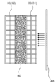
- FIG. 3 is a schematic diagram of the network structure manufacturing apparatus 1 shown in FIG. 2, as viewed from above. Specifically, FIG. 3 is a schematic diagram of the first conveying device 31, the second conveying device 32, and the network structure 60 of the network structure manufacturing apparatus 1, as viewed from above. Note that the nozzle 10 and the discharge hole 11 are omitted from FIG. 3.
- the water discharge device 43 preferably sprays cooling water onto only a portion of the width of the first conveying device 31 and the second conveying device 32.
- the portions of the width of the first conveying device 31 and the second conveying device 32 can be rephrased as a portion of the width of the mesh-like structure 60 located between the first conveying device 31 and the second conveying device 32. Since the water discharge device 43 sprays cooling water onto only a portion of the width of the first conveying device 31 and the second conveying device 32, it is possible to partially change the cooling speed of the linear resin 12 that constitutes the mesh-like structure 60 by the cooling water sprayed from the water discharge device 43.
- the water discharge devices 40, 43 may be one or more.
- the amount of water discharged from the water discharge devices 40, 43 is preferably 0.6 L/min or more and 3.0 L/min or less per 1 cm of width of the water discharge device.
- the discharged water partially changes the water flow rate, making it possible to partially change the cooling rate of the thermoplastic elastomer.
- the position where the cooling water is sprayed is preferably located 0.1 mm or more and 100 mm or less below the water surface in the water tank.
- additives that can impart functions such as deodorizing, antibacterial, antifungal, anti-mite, deodorizing, antifungal, aromatic, flame retardant, and moisture absorbing and releasing properties may be added to the thermoplastic resin.
- functional materials such as antioxidants and lubricants may be added to the raw material polybutylene adipate terephthalate resin. These may be used alone or in combination of two or more types. It is preferable to adjust the content of functional materials by kneading various functional materials into the resin during melt extrusion depending on the color tone and quality of the resin after melting.
- antioxidants examples include known phenol-based antioxidants, phosphite-based antioxidants, thioether-based antioxidants, benzotriazole-based ultraviolet absorbers, triazine-based ultraviolet absorbers, benzophenone-based ultraviolet absorbers, N-H type hindered amine-based light stabilizers, N-CH3 type hindered amine-based light stabilizers, etc. It is preferable to incorporate at least one of the above antioxidants into the thermoplastic resin.
- Phenol-based antioxidants include 1,3,5-tris[[3,5-bis(1,1-dimethylethyl)-4-hydroxyphenyl]methyl]-1,3,5-triazine-2,4,6(1H,3H,5H)-trione, 1,1,3-tris(2-methyl-4-hydroxy-5-tert-butylphenyl)butane, 4,4'-butylidenebis(6-tert-butyl-m-cresol), 3-(3,5-di-tert-butyl-4-hydroxyphenyl)stearyl propionate, pentaerythritol tetrakis[3-(3,5-di-tert-butyl-4-hydroxyphenyl)propionate], Sumilizer AG 80, and 2,4,6-tris(3',5'-di-tert-butyl-4'-hydroxybenzyl)mesitylene.
- Phosphite antioxidants include 3,9-bis(octadecyloxy)-2,4,8,10-tetraoxa-3,9-diphosphaspiro[5.5]undecane, 3,9-bis(2,6-di-tert-butyl-4-methylphenoxy)-2,4,8,10-tetraoxa-3,9-diphosphaspiro[5.5]undecane, 2,4,8,10-tetrakis(1,1-dimethylethyl)-6-[(2-ethylhexyl)oxy]-12H -Dibenzo[d,g]"1,3,2"dioxaphosphocin, tris(2,4-di-tert-butylphenyl) phosphite, tris(4-nonylphenyl) phosphite, 4,4'-isopropylidenediphenol C12-15 alcohol phosphite, diphenyl(2-ethylhexyl
- Thioether antioxidants include bis[3-(dodecylthio)propionic acid]2,2-bis[3-(dodecylthio)-1-oxopropyloxy]methyl]-1,3-propanediyl, and ditridecyl 3,3'-thiobispropionate.
- thermoplastic resin In order to prevent thermal degradation of the thermoplastic resin, a mixture of a phenol-based antioxidant and a phosphite-based antioxidant may be used.
- the total content of the two types of antioxidants is preferably 0.05% by mass or more and 1.0% by mass or less relative to 100% by mass of the thermoplastic resin composition.
- the characteristic values of the three-dimensional mesh structures of Examples 1 to 5 and Comparative Examples 1 to 3 were measured according to the following methods.
- the sample sizes were standardized as described below, but when there were insufficient samples, measurements were performed using samples of the largest possible size.
- the absorbance was measured using a SPECTROPHOTOMETER CM-3700d (manufactured by Konica Minolta, Inc.). A D65 light source was used as the light source, the viewing angle was set to 10°, the measurement range was set to a circle of ⁇ 8 mm, and the reflected light was measured. The measurement sample was cut into a length of 15 cm and a width of 15 cm from the obtained three-dimensional net structure, which was then cut into two parts in the thickness direction, one of which was designated as side A and the other as side B.
- the sample of side A was cut into small pieces with scissors, then passed through a sieve with a mesh size of 2.8 mm, and the part that passed through was further passed through a sieve with a mesh size of 0.5 mm, and the part remaining on the sieve was used.
- the size of the obtained sample was 0.5 to 3 mm. 12.4 ⁇ 0.9 g of this was placed in a ⁇ 38 mm cell, and the sample was sealed in a uniform state to measure the absorbance of side A.
- the absorbance of side B was measured in the same manner as side A, and the difference in absorbance between sides A and B was calculated.
- Deuterated chloroform was used as the lock solvent, the waiting time was 1 second, the data acquisition time was 4 seconds, and the number of integrations was 64.
- the chloroform peak was taken as 7.28 ppm, the adipic acid peak was detected at 2.45 ppm, and the terephthalic acid peak was detected at 8.15 ppm.
- the peak integral value of adipic acid is A and the peak integral value of terephthalic acid is B
- the polybutylene adipate terephthalate resin was synthesized in the following manner.
- ⁇ Resin P> In a reaction vessel equipped with a stirrer, a thermometer, and a distillation cooler, 1.5 moles of 1,4-butanediol, 0.40 moles of adipic acid, and 0.60 moles of dimethyl terephthalate were mixed. Next, 300 ppm of tetrabutyl titanate (manufactured by Aldrich Co.) was added to the mixture as a titanium catalyst. Thereafter, transesterification and esterification reactions were carried out at 220°C under normal pressure for 2 hours to prepare a prepolymer.
- the prepolymer was heated to 240°C, and then polycondensation reaction was carried out at 0.1 mmHg for 2 hours.
- the obtained resin P was cooled and then cut with a pellet cutter to produce pellets.
- the melting point of resin P was 150°C.
- the molar ratio of terephthalic acid units to adipic acid units in resin P was 1.5.
- Example 1 Resin P was used as a raw material, and the molten resin was discharged downward from the nozzle at a spinning temperature of 240° C. and a single-hole discharge rate of 3.87 g/min.
- the nozzle had an effective nozzle surface of 680 mm in width and 64 mm in thickness, and had orifices with an outer diameter of 5.0 mm and an inner diameter of 4.4 mm, each of which had a triple bridge hollow cross section, formed in a staggered arrangement with a hole pitch of 8 mm.
- the water tank was positioned so that the water surface in the tank (hereafter referred to as the water tank water surface) was located 31 cm below the nozzle surface of the nozzle for discharging the molten resin, and a pair of take-up conveyors were placed inside the tank so that a portion of them was above the water surface.
- the water temperature in the tank was 52°C.
- the take-up conveyor had a stainless steel endless net, and was positioned parallel to the width of the nozzle surface, with the opening width of the endless net being 48 mm.
- two aluminum plates were placed 660 mm apart at a 90-degree angle to the net and water surface to form the side portions.
- the molten resin was discharged into the opening of the net of the conveyor (between the two endless nets), and the continuous filaments were dropped to form a meandering loop, and the contact parts were fused to form a three-dimensional network structure.
- Both sides of the molten three-dimensional network structure were sandwiched by a take-up conveyor, and while 14°C cooling water was sprayed from the outside of one of the conveyor nets at a speed of 0.45 L/min at a position 50 mm below the water surface, it was pulled under the water surface of the water tank at a speed of 2.32 m/min and solidified. This flattened both sides in the thickness direction and the side direction. Next, it was cut to a specified size and left to stand in a space at 25°C for 1 hour. After that, it was heat-treated with 90°C hot air for 20 minutes to obtain a three-dimensional network structure.
- the cross-sectional shape of the continuous filaments constituting the three-dimensional network structure was a hollow structure.
- Example 2 A three-dimensional network structure was obtained in the same manner as in Example 1, except that a nozzle was used in which solid-forming orifices with an outer diameter of 1.0 mm were arranged in five rows with a hole pitch of 6 mm and triple-bridge hollow-forming orifices with an outer diameter of 5 mm and an inner diameter of 4.4 mm were arranged in nine rows with a hole pitch of 6 mm, the single-hole discharge rate was 1.35 g/min, the distance from the nozzle face to the water surface in the water tank was 25 cm, the take-up speed was 1.37 m/min, the water temperature in the water tank was 68°C, the cooling water was discharged 35 mm below the water surface, and the cooling water temperature was 12°C.
- Example 3 A three-dimensional network structure was obtained in the same manner as in Example 1, except that the spinning temperature was 220°C, the distance from the nozzle surface to the water surface of the water tank was 36 cm, the take-up speed was 1.91 m/min, the water temperature in the water tank was 55°C, the cooling water temperature was 12°C, and the cooling water discharge speed was 0.53 L/min.
- Example 4 A three-dimensional network structure was obtained in the same manner as in Example 1, except that a nozzle was used in which round-hole shaped orifices with an outer diameter of 1.0 mm were formed in a staggered arrangement with a hole pitch of 6 mm, the single-hole discharge rate was 1.50 g/min, the distance from the nozzle face to the water surface of the water tank was 20 cm, the take-up speed was 0.97 m/min, the water temperature in the water tank was 50° C., the cooling water discharge speed was 0.40 L/min, and the cooling water discharge position was 55 mm below the water surface of the water tank.
- the cross-sectional shape of the continuous filaments of the obtained three-dimensional network structure was round, and it had a solid structure.
- Example 5 A three-dimensional network structure was obtained in the same manner as in Example 1, except that the single-hole discharge rate was 3.00 g/min, the distance from the nozzle surface to the water surface in the water tank was 28 cm, the water temperature in the water tank was 57°C, and instead of spraying cooling water at a position 50 mm below the water surface, cooling water with a temperature of 14°C was discharged at a rate of 0.10 L/min from a water discharge device provided at a position 70 mm above one of the conveyor nets so as to contact the conveyor nets, and the take-up speed was 1.57 m/min. However, the molten resin discharged from the nozzle was not present on the extension line of the discharged water, and the water discharged from the water discharge device was not directly hit on the continuous filaments.
- Example 1 A three-dimensional network structure was obtained in the same manner as in Example 1, except that cooling water was not sprayed from the outside of the conveyor net when the molten three-dimensional network structure was transported.
- Example 2 A three-dimensional network structure was obtained in the same manner as in Example 3, except that cooling water was not sprayed from the outside of the conveyor net when the molten three-dimensional network structure was transported.
- Example 3 A three-dimensional network structure was obtained in the same manner as in Example 5, except that no cooling water was discharged from the water discharge device provided above the conveyor net when the three-dimensional network structure was formed.
- Network structure manufacturing device 10 Nozzle 11: Discharge hole 12: Linear resin 20: Water tank 30: Conveyor device 31: First conveyor device 32: Second conveyor device 40: Water discharge device 43: Water discharge device 60: Network structure
Landscapes
- Engineering & Computer Science (AREA)
- Textile Engineering (AREA)
- Chemical & Material Sciences (AREA)
- Chemical Kinetics & Catalysis (AREA)
- Treatment Of Fiber Materials (AREA)
- Nonwoven Fabrics (AREA)
Abstract
着色された材料を用いなくても目視で表裏を判別できる立体網状構造体を提供する。連続線条で構成された三次元ランダムループ接合構造を有する立体網状構造体であって、前記連続線条は、ポリブチレンアジペートテレフタレートを70質量%以上含み、前記立体網状構造体の厚み方向において対向する2つの面において、一方の面における波長500nmでの吸光度と他方の面における波長500nmでの吸光度との差の絶対値が0.020以上であることを特徴とする立体網状構造体。
Description
本発明は、立体網状構造体及びその製造方法に関するものである。
これまで、家具・ベッド等の寝具、電車・自動車・二輪車等の車両用座席に用いられるクッション材として、通気性やリサイクル性に優れている点から立体網状構造体が広く使用されている。また、昨今の環境問題への取り組みの加速から、従来のポリマーと比較して短時間で分解される生分解性ポリマーを用いた立体網状構造体について研究が進められており、これまでに種々の生分解性の立体網状構造体の技術が開示されている。
ところで、寝具や枕などにクッション材を用いた場合、衛生面や清潔性の観点から洗浄を行う際にクッション材からカバーを取り外して洗浄したり、カバーとクッション材とを別々に洗浄するのが一般的である。
例えば、特許文献1には、立体網状構造体の片面または両面に、連続気泡及び/又は連通空間を有する軟質ウレタンフォームを積層したクッション用中材が開示されており、衛生面の観点からクッション材を容易に水洗いすることが可能となっている。
寝具や枕などに用いられるクッション材は人体と接触する表側とその裏面である裏側とでは特性が異なっているが、一度カバーから取り外したクッション材をカバーに収納する際に、クッション材の表裏が目視では判別できず、表裏の判別に時間を要してしまうという問題点があった。また、表裏を誤ってクッション材をカバーに収納した場合に直前までの使用感から意図せず変化してしまう問題点があった。
従って、カバーから取り外す前と同じ使用感を得るためにはクッション材の表裏を目視で容易に判断できることが望ましい。しかし、特許文献1のクッション材は、厚み方向に均一な網状構造体であるため、一度カバーから取り出すとそれまでに使用していた面を判別することが難しい。一方、特許文献2には、マットレス長手方向に沿ってマーキング材が断続的に挿入されたマットレス用芯材が開示されており、目視で表裏が判別可能である。しかし、特許文献2では、マーキングを行うために着色された材料を別途用いる必要があるため、改良の余地があった。
本発明は、着色された材料を用いなくても目視で表裏を判別できる立体網状構造体を提供することを目的とする。
本発明者らは前記課題を解決するために鋭意検討した結果、立体網状構造体の一方の面における波長500nmでの吸光度と他方の面における波長500nmでの吸光度との差を大きくすることにより、立体網状構造体の表裏を判別できることを見いだした。
すなわち、本発明は、以下の発明を含む。
[1]連続線条で構成された三次元ランダムループ接合構造を有する立体網状構造体であって、前記連続線条を構成する熱可塑性樹脂組成物は、ポリブチレンアジペートテレフタレートを70質量%以上含み、前記立体網状構造体の厚み方向において対向する2つの面において、一方の面における波長500nmでの吸光度と他方の面における波長500nmでの吸光度との差の絶対値が0.020以上であることを特徴とする立体網状構造体。
[2]前記ポリブチレンアジペートテレフタレートはアジピン酸単位とテレフタル酸単位を含み、前記アジピン酸単位に対する前記テレフタル酸単位のモル比が0.8以上3.0以下である前記[1]に記載の立体網状構造体。
[3]クッション材として用いられる前記[1]又は[2]に記載の立体網状構造体。
[4]前記[1]又は[2]に記載の立体網状構造体を製造する製造方法であって、溶融された前記熱可塑性樹脂組成物をノズルより吐出する押出工程と、前記ノズルより吐出された前記連続線条を用いて立体網状構造に成型された成型体を得る成型工程と、前記成型体を熱処理する熱処理工程とを含み、前記成型工程は前記連続線条を水槽内で水に浸漬する工程と水放出装置により部分的に前記連続線条を冷却する工程とを含み、前記水放出装置から放出される冷却水は前記水槽内の水より5℃以上低い温度であることを特徴とする製造方法。
[1]連続線条で構成された三次元ランダムループ接合構造を有する立体網状構造体であって、前記連続線条を構成する熱可塑性樹脂組成物は、ポリブチレンアジペートテレフタレートを70質量%以上含み、前記立体網状構造体の厚み方向において対向する2つの面において、一方の面における波長500nmでの吸光度と他方の面における波長500nmでの吸光度との差の絶対値が0.020以上であることを特徴とする立体網状構造体。
[2]前記ポリブチレンアジペートテレフタレートはアジピン酸単位とテレフタル酸単位を含み、前記アジピン酸単位に対する前記テレフタル酸単位のモル比が0.8以上3.0以下である前記[1]に記載の立体網状構造体。
[3]クッション材として用いられる前記[1]又は[2]に記載の立体網状構造体。
[4]前記[1]又は[2]に記載の立体網状構造体を製造する製造方法であって、溶融された前記熱可塑性樹脂組成物をノズルより吐出する押出工程と、前記ノズルより吐出された前記連続線条を用いて立体網状構造に成型された成型体を得る成型工程と、前記成型体を熱処理する熱処理工程とを含み、前記成型工程は前記連続線条を水槽内で水に浸漬する工程と水放出装置により部分的に前記連続線条を冷却する工程とを含み、前記水放出装置から放出される冷却水は前記水槽内の水より5℃以上低い温度であることを特徴とする製造方法。
本発明では立体網状構造体の一方の面における波長500nmでの吸光度と他方の面における波長500nmでの吸光度との差を大きくすることにより、立体網状構造体の表裏を判別することができる。
本発明の立体網状構造体は、連続線条で構成された三次元ランダムループ接合構造を有する。
立体網状構造体の厚み方向において対向する2つの面において、一方の面における波長500nmでの吸光度と他方の面における波長500nmでの吸光度との差の絶対値(以下、両面の吸光度差という)が0.020以上である。両面の吸光度差が0.020以上であることにより、一方の面と他方の面との色目が大きく異なる。その結果、立体網状構造体の表裏を目視で容易に判別することができる。また、厚み方向で繊維径が異なる立体網状構造体であっても、両面の吸光度差が0.020以上であることによって目視での判別がより容易となる。両面の吸光度差は好ましくは0.035以上、より好ましくは0.060以上である。両面の吸光度差の上限は特に限定されないが、技術的な困難性から、例えば、0.200以下である。両面の吸光度差は分光測色計、分光光度計などで測定可能であり、例えば、後述の実施例に記載の測定方法で測定することができる。
以下では、各構成について詳細に説明する。
以下では、各構成について詳細に説明する。
<熱可塑性樹脂組成物>
連続線条を構成する熱可塑性樹脂組成物は、ポリブチレンアジペートテレフタレート樹脂を70質量%以上含有する。生分解性樹脂の中からポリブチレンアジペートテレフタレート樹脂を選択し、熱可塑性樹脂組成物100質量%に対してポリブチレンアジペートテレフタレート樹脂を70質量%以上含有した熱可塑性樹脂組成物を用いることによって、クッション性に優れた生分解性の立体網状構造体を得ることができる。ポリブチレンアジペートテレフタレート樹脂の含有量は、前記熱可塑性樹脂組成物に対して好ましくは75質量%以上、より好ましくは80質量%以上、さらに好ましくは90質量%以上、特に好ましくは95質量%以上である。また連続線条を構成する熱可塑性樹脂組成物は、ポリブチレンアジペートテレフタレート樹脂100質量%であってもよい。
連続線条を構成する熱可塑性樹脂組成物は、ポリブチレンアジペートテレフタレート樹脂を70質量%以上含有する。生分解性樹脂の中からポリブチレンアジペートテレフタレート樹脂を選択し、熱可塑性樹脂組成物100質量%に対してポリブチレンアジペートテレフタレート樹脂を70質量%以上含有した熱可塑性樹脂組成物を用いることによって、クッション性に優れた生分解性の立体網状構造体を得ることができる。ポリブチレンアジペートテレフタレート樹脂の含有量は、前記熱可塑性樹脂組成物に対して好ましくは75質量%以上、より好ましくは80質量%以上、さらに好ましくは90質量%以上、特に好ましくは95質量%以上である。また連続線条を構成する熱可塑性樹脂組成物は、ポリブチレンアジペートテレフタレート樹脂100質量%であってもよい。
ポリブチレンアジペートテレフタレート樹脂は、生分解性の樹脂であり、アジピン酸、テレフタル酸、及びブタンジオールとの共重合体である。ポリブチレンアジペートテレフタレート樹脂は生分解性を有することにより、ごみの廃棄問題やマイクロプラスチック問題に対する一つの解決策となることが期待される。アジピン酸、テレフタル酸、及びブタンジオールは、同時に共重合させる必要は無く、多段階的に共重合させてもよい。また、ポリブチレンアジペートテレフタレート樹脂は熱可塑性樹脂であることが好ましい。
ポリブチレンアジペートテレフタレート樹脂において、アジピン酸単位に対するテレフタル酸単位のモル比は0.8以上3.0以下であることが好ましい。前記モル比の下限は、より好ましくは1.0以上、さらに好ましくは1.1以上、特に好ましくは1.2以上である。一方、前記モル比の上限は、より好ましくは2.5以下、さらに好ましくは2.0以下である。前記モル比が0.8以上であることにより、立体網状構造体の使用環境温度での加熱圧縮後の圧縮回復性が向上し易くなる。一方、前記モル比が3.0以下であることにより、柔軟性が向上する。そのため、クッション材等に好適である。
ポリブチレンアジペートテレフタレート樹脂の融点は、120℃以上、180℃以下が好ましい。前記の融点の下限は、より好ましくは125℃以上、さらに好ましくは130℃以上、よりさらに好ましくは140℃以上、特に好ましくは145℃以上である。一方、前記の融点の上限は、より好ましくは170℃以下、さらに好ましくは160℃以下である。融点が120℃以上であることにより、立体網状構造体の使用環境温度での加熱圧縮後の圧縮回復性を向上し易くすることができる。一方、融点が180℃以下であることにより、柔軟性が向上して、クッション材等に好適に用いることができる。
ポリブチレンアジペートテレフタレート樹脂のメルトフローレート(MFR)は、好ましくは3g/10分~60g/10分である。MFRが3g/10分以上であると、溶融粘度を高くすることができ、連続線条の繊維径を大きくすることができる。前記のMFRの下限は、より好ましくは5g/10分以上、さらに好ましくは12g/10分以上、よりさらに好ましくは15g/10分以上、特に好ましくは18g/10分以上である。一方、前記のMFRが60g/10分以下であると、加熱圧縮後の圧縮回復性を向上し易くなる。前記のMFRの上限は、より好ましくは50g/10分以下、さらに好ましくは40g/10分以下、特に好ましくは30g/10分以下である。また連続線条を構成する熱可塑性樹脂組成物のMFRも当該範囲内であることが好ましい。樹脂のMFRは、後述する実施例に記載の方法により測定することができる。
ポリブチレンアジペートテレフタレート樹脂として、市販の樹脂を用いる際に、樹脂のメルトフローレート(MFR)が低い場合には、樹脂に水分を加えて溶融押出し時に樹脂を加水分解させることにより、樹脂のMFRを大きくすることができる。一方、樹脂のMFRが高い場合には、樹脂を乾燥させてから溶融押出しすることにより樹脂のMFRを小さくすることができる。
ポリブチレンアジペートテレフタレート樹脂の重量平均分子量(g/mol)は、好ましくは35000以上である。これにより、加熱圧縮後の圧縮回復性を向上することができる。重量平均分子量は、より好ましくは37000以上、さらに好ましくは40000以上である。一方、重量平均分子量が150000以下であることが好ましく、これにより柔軟性を向上することができる。より好ましくは120000以下である。また連続線条を構成する熱可塑性樹脂の重量平均分子量(g/mol)も当該範囲内であることが好ましい。重量平均分子量は、ゲル浸透クロマトグラフィー(GPC)等で求めることができる。
連続線条を構成する熱可塑性樹脂組成物は、ポリブチレンアジペートテレフタレート樹脂以外の他の生分解性樹脂を含んでいてもよい。他の生分解性樹脂としては、ポリ乳酸、ポリ乳酸/ポリカプロラクトン共重合体、ポリ乳酸/ポリエーテル共重合体、ポリエチレンテレフタレートサクシネート、ポリブチレンサクシネート、ポリブチレンサクシネートアジペート、ポリグリコール酸、ポリカプロラクトン、ポリビニルアルコール、酢酸セルロース等が好ましい。これらは単独でまたは2種類以上組み合わせて用いてもよい。これらの詳細は、日本バイオプラスチック協会のグリーンプラ(生分解性プラスチック)の分類番号A-1のポジティブリストを参照すればよい。連続線条を構成する熱可塑性樹脂組成物は、生分解性樹脂以外の樹脂を含んでいてもよい。当該樹脂として、ポリオレフィン、ポリウレタン、ポリエステル等の熱可塑性樹脂が挙げられる。
連続線条を構成する熱可塑性樹脂組成物は、防臭剤、抗菌剤、防カビ剤、防ダニ剤、消臭剤、防黴剤、芳香剤、難燃剤、吸放湿性剤、酸化防止剤、滑剤等を含んでいてもよい。これらは単独で、または2種類以上組み合わせて用いてもよい。
また、連続線条を構成する熱可塑性樹脂組成物は、ポリブチレンアジペートテレフタレート樹脂の他に、アジピン酸、テレフタル酸、ブタンジオール以外の他の共重合成分を単位に含む樹脂を加えてもよい。他の共重合成分として、テレフタル酸とアジピン酸以外の他のジカルボン酸、ブタンジオール以外の他のジオール、ポリアルキレングリコール、鎖延長や末端封鎖等を目的とした改質剤等が挙げられる。これらは単独で、または2種類以上組み合わせて用いてもよい。
他のジカルボン酸としては、シュウ酸、マロン酸、コハク酸、グルタル酸、ピメリン酸、スベリン酸等が挙げられる。これらは単独で、または2種類以上組み合わせて用いてもよい。
他のジオールとしては、メタンジオール、エタンジオール、プロパンジオール、ペンタンジオール、ヘキサンジオール等が挙げられる。ポリアルキレングリコールとしては、ポリメチレングリコール、ポリエチレングリコール、ポリプロピレングリコール、ポリブチレングリコール(ポリテトラメチレングリコール)等が挙げられる。これらは単独で、または2種類以上組み合わせて用いてもよい。
前記の改質剤としては、ポリイソシアネート化合物、グリコール化合物等が挙げられる。ポリイソシアネート化合物として、ジイソシアネート化合物が挙げられる。
ジイソシアネート化合物としては、ヘキサメチレンジイソシアネート、4,4’-ジフェニルメタンジイソシアネート、2,4-トリレンジイソシアネート、2,6-トリレンジイソシアネート、キシリレンジイソシアネート、1,5-ナフチレンジイソシアネート、p-フェニレンジイソシアネート、イソホロンジイソシアネート、4,4’-ジシクロヘキシルメタンジイソシアネート、テトラメチルキシレンジイソシアネート、カルボジイミド変性MDI、ポリメチレンフェニルポリイソシアネート等が挙げられる。これらは単独で、または2種類以上組み合わせて用いてもよい。
ジイソシアネート化合物としては、ヘキサメチレンジイソシアネート、4,4’-ジフェニルメタンジイソシアネート、2,4-トリレンジイソシアネート、2,6-トリレンジイソシアネート、キシリレンジイソシアネート、1,5-ナフチレンジイソシアネート、p-フェニレンジイソシアネート、イソホロンジイソシアネート、4,4’-ジシクロヘキシルメタンジイソシアネート、テトラメチルキシレンジイソシアネート、カルボジイミド変性MDI、ポリメチレンフェニルポリイソシアネート等が挙げられる。これらは単独で、または2種類以上組み合わせて用いてもよい。
連続線条を構成する熱可塑性樹脂組成物を合成するためのモノマーとして、石油由来のモノマーを用いてもよい。しかしながら、バイオマス由来のモノマーを用いることが、環境負荷の低減の点から好ましい。バイオマス由来のモノマーについては、例えば日本バイオプラスチック協会の分類番号A(バイオマスプラスチック)のポジティブリストに記載のモノマーを使用することができる。
連続線条を構成する熱可塑性樹脂組成物に含まれるジカルボン単位100モル%に対し、アジピン酸単位及びテレフタル酸単位の含有量の合計は、好ましくは70モル%以上、より好ましくは80モル%以上、さらに好ましくは90モル%以上、よりさらに好ましくは95モル%以上、特に好ましくは99モル%以上である。また、連続線条を構成する熱可塑性樹脂組成物に含まれるジオール単位100モル%に対し、ブタンジオール単位の含有量は、好ましくは70モル%以上、より好ましくは80モル%以上、さらに好ましくは90モル%以上、よりさらに好ましくは95モル%以上、特に好ましくは99モル%以上である。
<連続線条>
本発明の立体網状構造体は、熱可塑性樹脂組成物から構成される連続線条から構成され、三次元ランダムループ接合構造を有する。連続線条とは、少なくとも5mm以上の連続した部分を有する線条のフィラメントである。連続線条の交差部が接着してなる箇所を有することにより立体網状構造体を形成し易くなる。そのため、立体網状構造体は、連続線条どうしの交差部が接着している接着部を有していることが好ましい。
本発明の立体網状構造体は、熱可塑性樹脂組成物から構成される連続線条から構成され、三次元ランダムループ接合構造を有する。連続線条とは、少なくとも5mm以上の連続した部分を有する線条のフィラメントである。連続線条の交差部が接着してなる箇所を有することにより立体網状構造体を形成し易くなる。そのため、立体網状構造体は、連続線条どうしの交差部が接着している接着部を有していることが好ましい。
連続線条は、シース・コア型、サイドバイサイド型、偏芯シース・コア型等の複合線条体であってもよい。複合線条体は、ポリブチレンアジペートテレフタレート樹脂と、他の熱可塑性樹脂とを組み合わせた複合線条であってもよいし、異なる組成比のポリブチレンアジペートテレフタレート樹脂同士を組み合わせた複合線条であってもよい。連続線条の断面形状は、中空断面、中実断面のいずれでもよいが、軽量化の点から中空断面が好ましい。また、厚み方向や幅方向に異なる断面形状の繊維を複合してもよい。さらに、連続線条の断面形状は、異型断面であることが好ましい。これにより、立体網状構造体に好適な硬さやクッション性を付与し易くすることができる。連続線条の中空率の下限は、好ましくは1%以上、より好ましくは2%以上、特に好ましくは5%以上である。一方、連続線条の中空率の上限は、好ましくは30%以下、より好ましくは25%以下、特に好ましくは20%以下である。連続線条の中空率は、後述する実施例に記載の方法により測定することができる。
連続線条の平均繊維径は好ましくは0.2mm~2.0mmである。平均繊維径が0.2mm以上であることにより硬度が向上する。そのため平均繊維径は、より好ましくは0.3mm以上、さらに好ましくは0.4mm以上である。一方、平均繊維径が2.0mm以下であることにより、網状構造の緻密性を向上して、クッション性等を向上することができ、また網状構造の感触をソフトにし易くすることができる。そのため平均繊維径は、より好ましくは1.7mm以下であり、さらに好ましくは1.5mm以下、特に好ましくは1.2mm以下である。連続線条の平均繊維径は、後述する実施例に記載の方法により測定することができる。
連続線条は、融解エンタルピーが16J/g以上であることが好ましい。融解エンタルピーが16J/g以上であることにより、立体網状構造体の圧縮耐久性と、加熱圧縮後の圧縮回復性を向上することができる。融解エンタルピーは、より好ましくは17J/g以上、さらに好ましくは18J/g以上、よりさらに好ましくは19J/g以上、一層好ましくは20J/g以上、特に好ましくは21J/g以上である。一方、融解エンタルピーは、30J/g以下が好ましい。これにより、立体網状構造体の柔軟性が向上し、圧縮時と回復時のノイズの発生を低減することができる。融解エンタルピーは、より好ましくは28J/g以下、さらに好ましくは26J/g以下である。
連続線条の吸熱ピークのエンタルピー(J/g)は、サンプル質量を2.0mg±0.1mgとし、示差走査熱量計を用いて、窒素雰囲気下、昇温速度20℃/分で測定したDSC曲線から吸熱ピーク(融解ピーク)の積分値から求めることができる。積分値は、前記の吸熱ピーク(融解ピーク)に係る曲線が低温側のベースラインから離れ始める点を開始点とし、高温側のベースラインに接し始める点を終了点とし、前記の開始点と終了点と結ぶ直線を引き、前記の直線と曲線により囲まれた部分を積分することにより求めることができる。
<立体網状構造体>
立体網状構造体は、多層構造を有していてもよい。多層構造としては、表層と裏層を異なった繊度の連続線条で構成したもの、表層と裏層を異なった見かけ密度を有する構造体で構成したもの、あるいは長繊維不織布や短繊維不織布等を積層して多層化したもの等が挙げられる。多層化方法としては、加熱により溶融固着する方法、接着剤で接着させる方法、縫製やバンド等で拘束する方法等が挙げられる。
立体網状構造体は、多層構造を有していてもよい。多層構造としては、表層と裏層を異なった繊度の連続線条で構成したもの、表層と裏層を異なった見かけ密度を有する構造体で構成したもの、あるいは長繊維不織布や短繊維不織布等を積層して多層化したもの等が挙げられる。多層化方法としては、加熱により溶融固着する方法、接着剤で接着させる方法、縫製やバンド等で拘束する方法等が挙げられる。
立体網状構造体の形状は、特に限定されない。例えば、板状、三角柱、四角柱等の多角体、円柱、球状、これらの組み合わせ形状等が挙げられる。立体網状構造体を成形するに当たっては、樹脂の溶融押出し時に規制板を用いて成形してもよいし、カット、熱プレス等により成形してもよい。
立体網状構造体の見かけ密度は、好ましくは0.005g/cm3~0.30g/cm3である。見かけ密度が0.005g/cm3以上であることにより、立体網状構造体の硬度が向上する。その結果、立体網状構造体をクッション等に用いた場合に底付き感を低減できる。そのため、前記の見かけ密度の下限は、より好ましくは0.01g/cm3以上、さらに好ましくは0.02g/cm3以上、特に好ましくは0.03g/cm3以上である。
一方、前記の見かけ密度が0.30g/cm3以下であると、柔軟性が向上して、クッション材等に好適に用いることができる。そのため、前記の見かけ密度の上限は、より好ましくは0.20g/cm3以下、さらに好ましくは0.15g/cm3以下である。立体網状構造体の見かけ密度は、後述する実施例に記載の方法により測定することができる。
一方、前記の見かけ密度が0.30g/cm3以下であると、柔軟性が向上して、クッション材等に好適に用いることができる。そのため、前記の見かけ密度の上限は、より好ましくは0.20g/cm3以下、さらに好ましくは0.15g/cm3以下である。立体網状構造体の見かけ密度は、後述する実施例に記載の方法により測定することができる。
立体網状構造体の厚みは、好ましくは10mm~120mmである。厚みが10mm以上であることにより、立体網状構造体をクッション材等として用い易くなる。そのため、前記の厚みの下限は、より好ましくは15mm以上であり、さらに好ましくは20mm以上、特に好ましくは22mm以上である。一方、製造装置の大きさを考慮すると、前記の厚みの上限は、より好ましくは100mm以下、さらに好ましくは80mm以下、特に好ましくは50mm以下である。立体網状構造体の厚みは、後述する実施例に記載の方法により測定することができる。
立体網状構造体は、40℃圧縮残留歪みが25%以下であることが好ましい。これにより、加熱圧縮後の圧縮回復性を向上することができる。40℃圧縮残留歪みの上限は、より好ましくは22%以下、さらに好ましくは20%以下であり、特に好ましくは15%以下である。また40℃圧縮残留歪みは、1%以上であってもよく、5%以上であってもよい。40℃圧縮残留歪みは、後述する実施例に記載の方法により測定することができる。
立体網状構造体は、70℃圧縮残留歪みが30%以下であることが好ましい。これにより、加熱圧縮後の圧縮回復性を向上することができる。70℃圧縮残留歪みの上限は、より好ましくは25%以下、さらに好ましくは23%以下である。また70℃圧縮残留歪みは、1%以上であってもよく、5%以上であってもよい。70℃圧縮残留歪みは、後述する実施例に記載の方法により測定することができる。
立体網状構造体を厚み方向に25%圧縮したとき(75%の厚みに圧縮したとき)の圧縮時硬度(以下、「25%圧縮時硬度」という)は、好ましくは5.0N/φ200mm以上、100N/φ200mm以下である。立体網状構造体の25%圧縮時硬度が5.0N/φ200mm以上であることにより、立体網状構造体をクッション材等に用いた場合の底付き感を低減することができる。そのため、25%圧縮時硬度の下限は、より好ましくは5.4N/φ200mm以上、さらに好ましくは6.0N/φ200mm以上、特に好ましくは7.0N/φ200mm以上である。一方、25%圧縮時硬度は、100N/φ200mm以下であることにより、クッション性を向上することができる。そのため、25%圧縮時硬度の上限は、より好ましくは80N/φ200mm以下であり、さらに好ましくは60N/φ200mm以下、特に好ましくは30N/φ200mm以下である。25%圧縮時硬度は、後述する実施例に記載の方法により測定することができる。
立体網状構造体の融点は、120℃以上、180℃以下が好ましい。前記の融点の下限は、より好ましくは125℃以上、さらに好ましくは130℃以上、よりさらに好ましくは140℃以上、特に好ましくは145℃以上である。一方、前記の融点の上限は、より好ましくは170℃以下、さらに好ましくは160℃以下である。融点が120℃以上であることにより、立体網状構造体の使用環境温度での加熱圧縮後の圧縮回復性を向上し易くすることができる。一方、融点が180℃以下であることにより、柔軟性が向上して、クッション材等に好適に用いることができる。
立体網状構造体は、接合促進剤を含まない方が好ましい。これにより、接合促進剤による立体網状構造体内の過剰接合による過剰な硬化を防止し易くすることができる。また、1つの接点あたりの接合範囲が増えすぎることに伴う立体網状構造体の緻密性の低下を防止しやすくなる。前記の接合促進剤として、ポリカプロラクトン、ポリブチレンサクシネート、ポリブチレンセバケートテレフタレート、ポリブチレンアゼレートテレフタレート等が挙げられる。
本発明の立体網状構造体は、クッションに好適に用いられる。クッションは、物を支える弾力性を有するもの、または衝撃を少なくするものであればよい。クッションとして、オフィスチェア、家具、ソファー、ベッド等の寝具、電車、自動車、二輪車、チャイルドシート、ベビーカーなどの車両用座席等に用いられるクッション、フロアーマットや衝突、挟まれ防止部材等の衝撃吸収用マット等に用いられるクッションが挙げられる。
<立体網状構造体の製造方法>
立体網状構造体の製造方法としては、溶融された前記熱可塑性樹脂組成物をノズルより吐出する押出工程と、前記ノズルより吐出された前記連続線条を用いて立体網状構造に成型された成型体を得る成型工程と、前記成型体を熱処理する熱処理工程を含むことが好ましい。なお、熱処理工程終了前の立体網状構造体については完成品である立体網状構造体(熱処理工程終了後の立体網状構造体)との混同を避けるために成型体という。押出工程及び成型工程は公知の製造方法であれば特に限定されないが、具体的な製造方法としては例えば以下の方法が挙げられる。
まず、複数のオリフィスを持つ多列ノズルより、ポリブチレンアジペートテレフタレート系樹脂を含む熱可塑性樹脂組成物をノズルオリフィスに分配し、該樹脂の(融点+20℃)以上~(融点+180℃)未満の紡糸温度で、ノズルより下方に向け吐出させる。次いで、溶融状態で互いに連続線条を接触させて融着させて3次元網状構造を形成しつつ、引取りコンベアネットで挟み込み、水槽中の水で冷却する。このとき、水槽中の水とは別に、立体網状構造体の一方の面を水槽中の水より低い水温の水(以下、冷却水という)を用いて冷却することによって、両面の吸光度差を大きくすることができる。
立体網状構造体の製造方法としては、溶融された前記熱可塑性樹脂組成物をノズルより吐出する押出工程と、前記ノズルより吐出された前記連続線条を用いて立体網状構造に成型された成型体を得る成型工程と、前記成型体を熱処理する熱処理工程を含むことが好ましい。なお、熱処理工程終了前の立体網状構造体については完成品である立体網状構造体(熱処理工程終了後の立体網状構造体)との混同を避けるために成型体という。押出工程及び成型工程は公知の製造方法であれば特に限定されないが、具体的な製造方法としては例えば以下の方法が挙げられる。
まず、複数のオリフィスを持つ多列ノズルより、ポリブチレンアジペートテレフタレート系樹脂を含む熱可塑性樹脂組成物をノズルオリフィスに分配し、該樹脂の(融点+20℃)以上~(融点+180℃)未満の紡糸温度で、ノズルより下方に向け吐出させる。次いで、溶融状態で互いに連続線条を接触させて融着させて3次元網状構造を形成しつつ、引取りコンベアネットで挟み込み、水槽中の水で冷却する。このとき、水槽中の水とは別に、立体網状構造体の一方の面を水槽中の水より低い水温の水(以下、冷却水という)を用いて冷却することによって、両面の吸光度差を大きくすることができる。
その後、固化した成型体を引出し、水切りまたは乾燥して、両面または片面が平滑化した成型体を得る。これらの紡糸、冷却工程については、例えば、特開平7-68061号公報の記載を参照することができる。片面のみを平滑化させる場合は、傾斜を持つ引取ネット上に連続線条を吐出させて、溶融状態で連続線条を互いに接触させて融着させればよい。その際、3次元網状構造を形成しつつ、引取ネット面のみ形態を緩和させつつ冷却すればよい。得られた成型体に対して、熱処理を行う。なお、成型体の乾燥処理を熱処理としてもよい。
ポリブチレンアジペートテレフタレート樹脂は、冷却固化されるまでに成形収縮が生じる場合がある。そのため、成形収縮を考慮した幅と厚みの立体網状構造体を形成すればよい。例えば、溶融固化温度を低くすることにより成形収縮を低減することができる。水槽中の水の温度は、好ましくは80℃以下、より好ましくは70℃以下である。水槽中の水の温度の下限は特に限定されず、例えば、30℃以上である。また、水による冷却時間は30秒以上が好ましい。前記の冷却固化は水槽内で行うことが好ましい。
両面の吸光度差を大きくする方法としては、上述のとおり、立体網状構造体の一方の面を水槽中の水より低い水温の冷却水を用いて冷却すればよく、例えば、一方のコンベアネットの外側から冷却水を放出する方法やコンベアネット上から冷却水を放出する方法が挙げられる。なお、コンベアネット上から冷却水を放出する方法では、冷却水の放出方向の延長線上には立体網状構造体は存在していない。これらの方法の詳細については図1及び図2を用いて後述する。
両面の吸光度差を大きくするためには、冷却水の水温は水槽中の水より5℃以上低いことが好ましく、10℃以上低いことがより好ましく、20℃以上低いことがさらに好ましく、30℃以上低いことが特に好ましい。冷却水の水温が水槽中の水より5℃以上低いことで十分な吸光度差が得られる。上記の方法により得られた立体網状構造体は両面の吸光度差が大きいため、立体網状構造体の表裏を目視での判別することが容易となる。なお、上記の製造方法を使用した場合、両面の平均繊維径の差は小さくなり、両面の平均繊維径の中で大きい方の値を小さい方の値で除した値が1.0~1.6であることが好ましく、1.0~1.2であることがより好ましく、1.0超1.05以下であることがさらに好ましい。また、上記の製造方法を使用した場合、両面の硬度(後述の25%圧縮時硬度)の差も小さくなり、両面の硬度の中で大きい方の値を小さい方の値で除した値が1.0~1.6であることが好ましく、1.0~1.2であることがより好ましく、1.0超1.05以下であることがさらに好ましい。したがって、厚み方向に一様なノズルを用いて立体網状構造体を製造した場合、両面で同様のクッション性となる立体網状構造体を得ることができる。
また、上記の製造方法で立体網状構造体を製造することで着色剤などの添加剤を使用せずに、目視での判別が容易な立体網状構造体を製造することができる。着色剤などの添加剤を使用しないことにより、立体網状構造体をリサイクルすることができ、使用済みの立体網状構造体を再び立体網状構造体の原料等として利用することができる。
ノズルから吐出する前の熱可塑性樹脂組成物に水を加えてもよい。熱可塑性樹脂組成物に水を添加することにより立体網状構造体の製造工程における熱可塑性樹脂の加水分解を促進し、樹脂の柔軟性を向上することができる。一方、水の仕込み量は、熱可塑性樹脂組成物に対して、好ましくは2.0質量%以下である。これにより、立体網状構造体の製造工程における熱可塑性樹脂の過剰な分解を防止することができる。その結果、加熱圧縮後の圧縮回復性が向上し易くなる。また、熱可塑性樹脂組成物に水を加える方法は特に限定されない。例えば、樹脂をノズルから吐出する前に、熱可塑性樹脂組成物を100℃で12時間以上、真空乾燥して絶乾させる。次いで、絶乾した熱可塑性樹脂組成物100質量%に対して、所定の量の純水を加えればよい。
ポリブチレンアジペートテレフタレート樹脂のメルトフローレート(MFR)は、溶融押出しをする前の時点で、所望の立体網状構造体を構成する連続線条のMFRよりも、0.5以上、20.0未満小さいことが好ましい。溶融押出し時に樹脂の熱劣化やせん断劣化が誘起されるため、溶融押出し前のMFRを上記のように制御することにより、所望のMFRを有する連続線条が得られ易くなる。
熱処理は、市販の熱風乾燥炉を用いて行ってもよく、温水浴中で行ってもよい。なお、熱処理は水槽中の水の温度より5℃以上高い温度で行うことが好ましい。また、熱処理温度は50℃以上が好ましい。これにより融解エンタルピーを大きくすることができる。前記の熱処理温度は、より好ましくは60℃以上、さらに好ましくは70℃以上である。前記の熱処理は、異なる温度で複数回に分けて行ってもよい。
前記熱処理を実施するにあたっては、連続線条を構成する熱可塑性樹脂組成物の融点は120℃以上、180℃以下が好ましい。前記の融点の下限は、より好ましくは125℃以上、さらに好ましくは130℃以上、よりさらに好ましくは140℃以上、特に好ましくは145℃以上である。一方、前記の融点の上限は、より好ましくは170℃以下、さらに好ましくは160℃以下である。融点が120℃以上であることにより、好適な温度範囲で熱処理を実施することができる。一方、融点が180℃以下であることにより、柔軟性が向上して、クッション材等に好適に用いることができる。
熱処理工程における熱処理時間は、好ましくは1分以上である。これにより融解エンタルピーを大きくすることができる。前記の熱処理時間は、より好ましくは5分以上、さらに好ましくは10分以上、特に好ましくは15分以上である。一方、熱処理工程における熱処理時間の上限は、好ましくは60分以下、より好ましくは50分以下である。これにより、熱処理時のポリマーの分解や劣化等に伴うポリブチレンアジペートテレフタレート樹脂の黄変、臭気、分子量低下等を低減することができる。さらに、生産性を向上することもできる。
水槽で冷却固化した成型体は、熱処理前に20℃~50℃の温度にて1分以上(好ましくは10分以上、より好ましくは30分以上)保持することが好ましい。熱処理では自重によって、成型体の厚みが変化する場合がある。しかしながら、冷却固化後に20℃~50℃の温度で保持することにより、熱処理による成型体の厚みの変化を低減することができる。例えば、水槽で冷却固化した後に、連続式乾燥機を用いて、熱風オーブンの前半の温度を低くして保持し、更に熱風オーブンの後半の温度を高くして熱処理を行ってもよい。
図1及び図2は、本発明の実施の形態における網状構造体製造装置の側面図である。網状構造体製造装置1は、ノズル10、水槽20、搬送装置30、及び水放出装置40又は43を有している。図1及び図2の説明では、立体網状構造体を網状構造体ということがある。なお、図2では水放出装置40に代えて水放出装置43を設けている点が図1とは異なっており、後述の実施例1~4では図1の装置を、後述の実施例5では図2の装置を用いている。
ノズル10は、溶融した熱可塑性樹脂を線条にして押し出す吐出孔11を有している。即ち、加熱によって溶融した熱可塑性樹脂をノズル10の吐出孔11から押し出すことにより、線条の樹脂12を形成している。
ノズル10が有している吐出孔11は、1列に配置されていてもよいが、複数列であることが好ましい。ノズル10が複数の吐出孔11を有していることにより、同時に複数の線条の樹脂12を形成することができ、網状構造体60の生産効率を高めることができる。ノズル10が有している吐出孔11の数は、製造する網状構造体60の硬度やクッション性に応じて調節することができる。
吐出孔11から押し出された線条の樹脂12の断面形状は、中実であってもよく、中空であってもよい。線条の樹脂12の断面形状を中空とするためには、例えば、吐出孔11の内側に心棒のような心金部を有する構成であればよい。具体的には、吐出孔11の出口の断面形状が、吐出孔11の内側と外側とが一部連通している、所謂C型ノズルや、吐出孔11にブリッジを設けて、吐出孔11を周方向に分割した、所謂3点ブリッジ形状ノズル等が挙げられる。
水槽20は、ノズル10の下方に配置されており、ノズル10の吐出孔11から押し出された線条の樹脂12を受け入れ可能に構成されている。水槽20は、ノズル10の吐出孔11から押し出された線条の樹脂12を冷却する水を有している。ノズル10の吐出孔11から押し出された線条の樹脂12は、水槽20内の水面に着水して曲がりくねることによってランダムループを形成し、隣接するランダムループと互いに溶融状態で接触することで、三次元方向にランダムループ同士が接合した構造体を形成し、同時に水によって冷却されその構造が固定される。このようにして網状構造体60が得られる。
搬送装置30は、水槽20に設けられており、線条の樹脂12を有する網状構造体60を搬送する。つまり、搬送装置30は、ノズル10の吐出孔11から押し出され、水槽20内に受け入れた線条の樹脂12を有する網状構造体60を水槽20内で搬送する。搬送装置30は、水槽20の水面から水槽20の底部に向かって、網状構造体60を搬送することが好ましい。
搬送装置30は、少なくとも第1搬送装置31と第2搬送装置32から構成されており、第1搬送装置31と第2搬送装置32との間に網状構造体60がある。搬送装置30がこのように構成されていることにより、網状構造体60を第1搬送装置31と第2搬送装置32とで挟んだ状態で搬送することができるため、表面が整っており、また、厚みが一定である網状構造体60とすることができる。
図1に示すように、水放出装置40は、搬送装置30の上部に設けられており、所定の方向へ水を放出する。水放出装置40の水の放出方向の延長線上には、搬送装置30の間にある網状構造体60は存在していない。十分な冷却速度差を得るためには、冷却水を放出していない時点での線条体の着水部の水面温度と放出する冷却水との水温差は5℃以上であることが好ましい。水温差が5℃未満では十分な接点数差が得られないことがある。また、前記水温差は10℃以上であることがより好ましい。水温差が10℃未満では融点以下に発現する吸熱ピークトップの温度差が1℃以上とならないことがある。
搬送装置の上部から供給される冷却水の水量は、搬送装置の幅1cmあたり0.04L/min以上、0.9L/min以下が好ましい。0.04L/min未満の場合、十分に樹脂の冷却速度を向上させることができない。0.9L/minより多いと、網状構造体表面の成形不良が起こり表面の品位が悪化する。また、樹脂の冷却は、冷却水の速度を部分的に変更することによっても達成可能である。水放出装置40は網状構造体における帯状に硬度を低下させたい所望の位置に配置され、水槽20の水面よりも0.1mm以上、100mm以下の上方に離れた位置に配置されていることが好ましい。
図2では、冷却水を放出する水放出装置43を有しており、水放出装置43による冷却水の噴出位置は、水槽20の水面よりも下方であることが好ましい。図1に示すように、水放出装置40による冷却水の噴出位置が水槽20の水面よりも上方である場合、ノズル10の吐出孔11から押し出された線条の樹脂12が、水槽内の冷却水に着水する前に水放出装置40から噴出された冷却水に接触すると、線条の樹脂12が大きく曲がる等して網状構造体の表面に大きな凹凸が生じ、地合が悪くなってしまうことがある。そのため、水放出装置40による冷却水の噴出位置が水槽20の水面よりも上方である場合には、水放出装置40による冷却水の噴出の角度やノズル10の吐出孔11の角度等を調整する必要がある。
一方、図2に示すように、水放出装置43による冷却水の噴出位置が水槽20の水面よりも下方である場合、ノズル10の吐出孔11から押し出された線条の樹脂12が、水槽内の冷却水に着水する前に水放出装置43から噴出された冷却水に接触するおそれがなく、網状構造体の地合の低下を生じにくくすることができる。そのため、水放出装置43による冷却水の噴出位置は、水槽20の水面よりも上方であることよりも、水槽20の水面よりも下方であることの方が好ましい。
図3は、図2に示した網状構造体製造装置1を上方から見た模式図である。具体的には、図3は、網状構造体製造装置1の第1搬送装置31、第2搬送装置32、および網状構造体60を上方から見た模式図である。なお、図3において、ノズル10および吐出孔11の図示は省略している。
図3に示すように、水放出装置43は、第1搬送装置31および第2搬送装置32の幅方向の一部のみに冷却水を噴出していることが好ましい。第1搬送装置31および第2搬送装置32の幅方向の一部は、第1搬送装置31と第2搬送装置32との間に位置している網状構造体60の幅方向の一部と言い換えることができる。水放出装置43が第1搬送装置31および第2搬送装置32の幅方向の一部のみに冷却水を噴出していることにより、水放出装置43から噴出される冷却水によって、網状構造体60を構成する線条の樹脂12の冷却速度を部分的に変更することが可能である。
水放出装置40、43は、1つであってもよく、複数であってもよい。水放出装置40、43から放出する水量は水放出装置の幅1cm当たり、0.6L/min以上、3.0L/min以下が好ましい。放出された水により、水の流速が部分的に変化し部分的に熱可塑性エラストマーの冷却速度を変化させることが可能となる。冷却水の噴出位置は水槽内における水面よりも0.1mm以上、100mm以下の下方に配置されていることが好ましい。
立体網状構造体の原料として使用される熱可塑性樹脂の製造工程から成形工程までの任意の段階で、熱可塑性樹脂に、防臭抗菌性、防カビ性、防ダニ性、消臭性、防黴性、芳香性、難燃性、吸放湿性等の機能を付与できる添加剤を含有させてもよい。また、立体網状構造体を製造するに当たって、原料であるポリブチレンアジペートテレフタレート樹脂に、酸化防止剤、滑剤などの機能付与材を含有させてもよい。これらは単独で、または2種類以上組み合わせて用いてもよい。樹脂の溶融後の色調や品位に応じて、溶融押出し時に各種の機能付与材を樹脂に混練りして機能付与材の含有量を調整することが好ましい。
酸化防止剤としては、公知のフェノール系酸化防止剤、ホスファイト系酸化防止剤、チオエーテル系酸化防止剤、ベンゾトリアゾール系紫外線吸収剤、トリアジン系紫外線吸収剤、ベンゾフェノン系紫外線吸収剤、N-H型ヒンダードアミン系光安定剤、N-CH3型ヒンダードアミン系光安定剤等が挙げられる。前記の酸化防止剤のうち、少なくとも1種を熱可塑性樹脂に含有させることが好ましい。
フェノール系酸化防止剤としては、1,3,5-トリス[[3,5-ビス(1,1-ジメチルエチル)-4-ヒドロキシフェニル]メチル]-1,3,5-トリアジン-2,4,6(1H,3H,5H)-トリオン、1,1,3-トリス(2-メチル-4-ヒドロキシ-5-tert-ブチルフェニル)ブタン、4,4’-ブチリデンビス(6-tert-ブチル-m-クレゾール)、3-(3,5-ジ-tert-ブチル-4-ヒドロキシフェニル)プロピオン酸ステアリル、ペンタエリトリトールテトラキス[3-(3,5-ジ-tert-ブチル-4-ヒドロキシフェニル)プロピオナート]、Sumilizer AG 80、2,4,6-トリス(3’,5’-ジ-tert-ブチル-4’-ヒドロキシベンジル)メシチレン等が挙げられる。
ホスファイト系酸化防止剤としては、3,9-ビス(オクタデシルオキシ)-2,4,8,10-テトラオキサ-3,9-ジホスファスピロ[5.5]ウンデカン、3,9-ビス(2,6-ジ-tert-ブチル-4-メチルフェノキシ)-2,4,8,10-テトラオキサ-3,9-ジホスファスピロ[5.5]ウンデカン、2,4,8,10-テトラキス(1,1-ジメチルエチル)-6-[(2-エチルヘキシル)オキシ]-12H-ジベンゾ[d,g]「1,3,2」ジオキサホスホシン、亜リン酸トリス(2,4-ジ-tert-ブチルフェニル)、亜リン酸トリス(4-ノニルフェニル)、4,4’-Isopropylidenediphenol C12-15 alcohol phosphite、亜リン酸ジフェニル(2-エチルヘキシル)、ジフェニルイソデシルホスファイト、トリイソデシル ホスファイト、亜リン酸トリフェニル等が挙げられる。
チオエーテル系酸化防止剤としては、ビス[3-(ドデシルチオ)プロピオン酸]2,2-ビス[「3-(ドデシルチオ)-1-オキソプロピルオキシ」メチル]-1,3-プロパンジイル、3,3’-チオビスプロピオン酸ジトリデシル等が挙げられる。
熱可塑性樹脂の熱劣化を防ぐために、フェノール系酸化防止剤とホスファイト系酸化防止剤を混合して使用してもよい。これらの2種の酸化防止剤を使用する場合、2種の酸化防止剤の合計の含有量は、熱可塑性樹脂組成物100質量%に対して、好ましくは0.05質量%以上、1.0質量%以下である。
滑剤は、炭化水素系ワックス、高級アルコール系ワックス、アミド系ワックス、エステル系ワックス、金属石鹸系等が挙げられる。必要に応じて、熱可塑性樹脂組成物100質量%に対して、滑剤を質量基準で好ましくは0.5質量%以下含有させる。
本願は、2023年3月30日に出願された日本国特許出願第2023-056166号に基づく優先権の利益を主張するものである。2023年3月30日に出願された日本国特許出願第2023-056166号の明細書の全内容が、本願に参考のため援用される。
以下、実施例を挙げて本発明をより具体的に説明する。なお、本発明は下記実施例によって制限されない。また、前・後記の趣旨に適合し得る範囲で変更を加えて実施することも可能であり、それらはいずれも本発明の技術的範囲に包含される。
下記の実施例1~5、比較例1~3の立体網状構造体の特性値は、下記の方法に基づいて測定した。なお、試料の大きさは、下記に記載の大きさを標準としたが、試料が不足する場合には、可能な大きさの試料を用いて測定を行った。
(1)吸光度
SPECTROPHOTOMETER CM-3700d(コニカミノルタ株式会社製)を用いて吸光度を測定した。光源にはD65光源を使用し、視野角は10°、測定範囲をΦ8mmの円に設定し反射光を測定対象とした。測定用試料は、得られた立体網状構造体を縦15cm、横15cmに切り出し、それを厚み方向に2分割となるように切断し、一方をA面、他方をB面とした。A面の試料をはさみで細かく切断した後、目開き2.8mmのふるいにかけ、通過したものをさらに目開き0.5mmのふるいにかけ、そのふるい上に残ったものを使用した。得られた試料(網状体切片)の大きさは0.5~3mmであった。これをΦ38mmのセルに12.4±0.9g入れ均一にならした状態で封入したものを測定用試料としてA面の吸光度を測定した。B面の吸光度もA面と同様に測定し、A面とB面の吸光度差を算出した。
SPECTROPHOTOMETER CM-3700d(コニカミノルタ株式会社製)を用いて吸光度を測定した。光源にはD65光源を使用し、視野角は10°、測定範囲をΦ8mmの円に設定し反射光を測定対象とした。測定用試料は、得られた立体網状構造体を縦15cm、横15cmに切り出し、それを厚み方向に2分割となるように切断し、一方をA面、他方をB面とした。A面の試料をはさみで細かく切断した後、目開き2.8mmのふるいにかけ、通過したものをさらに目開き0.5mmのふるいにかけ、そのふるい上に残ったものを使用した。得られた試料(網状体切片)の大きさは0.5~3mmであった。これをΦ38mmのセルに12.4±0.9g入れ均一にならした状態で封入したものを測定用試料としてA面の吸光度を測定した。B面の吸光度もA面と同様に測定し、A面とB面の吸光度差を算出した。
(2)平均繊維径
立体網状構造体を10cm×10cmの大きさに切断し、それぞれ10箇所から連続線条を約5mmの長さで採集した。次いで、光学顕微鏡を用いて採集した連続線条の繊維径を測定する箇所にピントを合わせて径を測定し、10箇所の繊維径の平均値(n=10)を求めた。
立体網状構造体を10cm×10cmの大きさに切断し、それぞれ10箇所から連続線条を約5mmの長さで採集した。次いで、光学顕微鏡を用いて採集した連続線条の繊維径を測定する箇所にピントを合わせて径を測定し、10箇所の繊維径の平均値(n=10)を求めた。
(3)中空率
立体網状構造体からランダムに10本の連続線条を取り出した。次いで連続線条を輪切りにし、繊維軸方向に立てた状態でスライドガラスに載せ、光学顕微鏡で輪切り方向の繊維断面を観察した。この際、繊維断面が中空断面である連続線条のみを選択し、繊維の外周線内の面積(a)と中空部の面積(b)をそれぞれ算出し、下記式に基づいて中空率を算出し、選択した中空断面の連続線条の中空率の平均値(n=10)を求めた。
中空率(%)=(b)/(a)×100
立体網状構造体からランダムに10本の連続線条を取り出した。次いで連続線条を輪切りにし、繊維軸方向に立てた状態でスライドガラスに載せ、光学顕微鏡で輪切り方向の繊維断面を観察した。この際、繊維断面が中空断面である連続線条のみを選択し、繊維の外周線内の面積(a)と中空部の面積(b)をそれぞれ算出し、下記式に基づいて中空率を算出し、選択した中空断面の連続線条の中空率の平均値(n=10)を求めた。
中空率(%)=(b)/(a)×100
(4)厚み、見かけ密度
立体網状構造体を縦横方向に10cm×10cmの大きさに切断し、得られた試料を無荷重で24時間放置した。その後、試験片測厚器(高分子計器株式会社製、FD-80N型)を用いて、中心1か所の高さを測定し、その試料の高さを立体網状構造体の厚みとした。更に、試料を電子天秤に載せて試料の重さを計測した。試料の高さと縦横の面積(100cm2)を乗じて試料の体積を求め、試料の重さを体積で除して、見かけ密度を求めた。前記の操作を3回行って、立体網状構造体の厚み及び見かけ密度の平均値(n=3)を求めた。
立体網状構造体を縦横方向に10cm×10cmの大きさに切断し、得られた試料を無荷重で24時間放置した。その後、試験片測厚器(高分子計器株式会社製、FD-80N型)を用いて、中心1か所の高さを測定し、その試料の高さを立体網状構造体の厚みとした。更に、試料を電子天秤に載せて試料の重さを計測した。試料の高さと縦横の面積(100cm2)を乗じて試料の体積を求め、試料の重さを体積で除して、見かけ密度を求めた。前記の操作を3回行って、立体網状構造体の厚み及び見かけ密度の平均値(n=3)を求めた。
(5)ポリブチレンアジペートテレフタレート樹脂のアジピン酸単位に対するテレフタル酸単位のモル比
ポリブチレンアジペートテレフタレート樹脂のアジピン酸単位に対するテレフタル酸単位のモル比は、共鳴周波数600MHzの1H-NMRにより測定した。測定装置はBRUKER社製NMR装置AVANCE-NEO600を用い、測定は以下の通りに行った。
試料10~15mgを重クロロホルム/トリフルオロ酢酸=85/15(容量比)に溶解後、その溶液をNMRチューブに充填し測定を行った。ロック溶媒には重クロロホルムを用い、待ち時間を1秒、データ取り込み時間を4秒、積算回数を64回とした。
クロロホルムのピークを7.28ppmとした時、アジピン酸のピークは2.45ppmに、テレフタル酸のピークは8.15ppmに検出される。
アジピン酸のピーク積分値をA、テレフタル酸の積分値をBとした時、ポリブチレンアジペートテレフタレート樹脂のアジピン酸単位に対するテレフタル酸単位のモル比は、下記式にて表すことができる。
モル比=((B/4)÷(A/4))
ポリブチレンアジペートテレフタレート樹脂のアジピン酸単位に対するテレフタル酸単位のモル比は、共鳴周波数600MHzの1H-NMRにより測定した。測定装置はBRUKER社製NMR装置AVANCE-NEO600を用い、測定は以下の通りに行った。
試料10~15mgを重クロロホルム/トリフルオロ酢酸=85/15(容量比)に溶解後、その溶液をNMRチューブに充填し測定を行った。ロック溶媒には重クロロホルムを用い、待ち時間を1秒、データ取り込み時間を4秒、積算回数を64回とした。
クロロホルムのピークを7.28ppmとした時、アジピン酸のピークは2.45ppmに、テレフタル酸のピークは8.15ppmに検出される。
アジピン酸のピーク積分値をA、テレフタル酸の積分値をBとした時、ポリブチレンアジペートテレフタレート樹脂のアジピン酸単位に対するテレフタル酸単位のモル比は、下記式にて表すことができる。
モル比=((B/4)÷(A/4))
(6)40℃圧縮残留歪み
立体網状構造体を10cm×10cmの大きさに切断した。次いで、得られた試料について上記(4)に記載の方法で処理前の厚み(c)を測定した。厚みを測定したサンプルを50%圧縮状態に保持できる冶具に挟み、40℃に制御した乾燥機に入れて22時間放置した。その後、サンプルを取り出し、冷却して圧縮歪みを除いて30分放置した後の厚み(d)を求めた。これらの厚みを下記式に入力し、40℃圧縮残留歪みを求めた。前記の操作を3回行って、40℃圧縮残留歪みの平均値(n=3)を求めた。
40℃圧縮残留歪み(%)=((c)-(d))/(c)×100
立体網状構造体を10cm×10cmの大きさに切断した。次いで、得られた試料について上記(4)に記載の方法で処理前の厚み(c)を測定した。厚みを測定したサンプルを50%圧縮状態に保持できる冶具に挟み、40℃に制御した乾燥機に入れて22時間放置した。その後、サンプルを取り出し、冷却して圧縮歪みを除いて30分放置した後の厚み(d)を求めた。これらの厚みを下記式に入力し、40℃圧縮残留歪みを求めた。前記の操作を3回行って、40℃圧縮残留歪みの平均値(n=3)を求めた。
40℃圧縮残留歪み(%)=((c)-(d))/(c)×100
(7)70℃圧縮残留歪み
立体網状構造体を10cm×10cmの大きさに切断した。次いで、得られた試料について上記(4)に記載の方法で処理前の厚み(c)を測定した。厚みを測定したサンプルを50%圧縮状態に保持できる冶具に挟み、70℃に制御した乾燥機に入れて22時間放置した。その後、サンプルを取り出し、冷却して圧縮歪みを除いて30分放置した後の厚み(e)を求めた。これらの厚みを下記式に入力し、70℃圧縮残留歪みを求めた。前記の操作を3回行って、70℃圧縮残留歪みの平均値(n=3)を求めた。
70℃圧縮残留歪み(%)=((c)-(e))/(c)×100
立体網状構造体を10cm×10cmの大きさに切断した。次いで、得られた試料について上記(4)に記載の方法で処理前の厚み(c)を測定した。厚みを測定したサンプルを50%圧縮状態に保持できる冶具に挟み、70℃に制御した乾燥機に入れて22時間放置した。その後、サンプルを取り出し、冷却して圧縮歪みを除いて30分放置した後の厚み(e)を求めた。これらの厚みを下記式に入力し、70℃圧縮残留歪みを求めた。前記の操作を3回行って、70℃圧縮残留歪みの平均値(n=3)を求めた。
70℃圧縮残留歪み(%)=((c)-(e))/(c)×100
(8)25%圧縮時硬度
立体網状構造体を30cm×30cmの大きさに切断し、得られた試料を23℃±2℃の環境下に無荷重で24時間放置した。次いで、23℃±2℃の環境下で株式会社島津製作所製オートグラフAG-X plusを用いて、ISO2439(2008)E法に準拠して計測した。具体的には、直径(φ)200mmの加圧板を試料の中心位置に配置して、荷重が5Nになったときの厚みを計測し、それを初期厚みとした。このときの加圧板の位置をゼロ点として、速度100mm/分で初期厚みの75%まで予備圧縮を1回行い、同じ速度で加圧板をゼロ点まで戻した後、そのままの状態で4分間放置した。その後、即座に速度100mm/分で初期厚みの25%まで圧縮を行って、その際の荷重を測定し、その加重を25%圧縮時硬度(N/φ200mm)とした。前記の操作を3回行って、25%圧縮時硬度の平均値(n=3)を求めた。
立体網状構造体を30cm×30cmの大きさに切断し、得られた試料を23℃±2℃の環境下に無荷重で24時間放置した。次いで、23℃±2℃の環境下で株式会社島津製作所製オートグラフAG-X plusを用いて、ISO2439(2008)E法に準拠して計測した。具体的には、直径(φ)200mmの加圧板を試料の中心位置に配置して、荷重が5Nになったときの厚みを計測し、それを初期厚みとした。このときの加圧板の位置をゼロ点として、速度100mm/分で初期厚みの75%まで予備圧縮を1回行い、同じ速度で加圧板をゼロ点まで戻した後、そのままの状態で4分間放置した。その後、即座に速度100mm/分で初期厚みの25%まで圧縮を行って、その際の荷重を測定し、その加重を25%圧縮時硬度(N/φ200mm)とした。前記の操作を3回行って、25%圧縮時硬度の平均値(n=3)を求めた。
(9)表裏の判別
得られた試料を準備して、大人の被験者5名がA面とB面の差異を認識できるか目視で判断した。3名以上が「可能」であれば「判別可」、3名以上が不可能であれば「判別不可」とした。
得られた試料を準備して、大人の被験者5名がA面とB面の差異を認識できるか目視で判断した。3名以上が「可能」であれば「判別可」、3名以上が不可能であれば「判別不可」とした。
ポリブチレンアジペートテレフタレート樹脂は以下の方法で合成した。
<樹脂P>
攪拌機、温度計、留出用冷却器を備えた反応釜内に、1,4-ブタンジオールを1.5モル、アジピン酸を0.40モル、およびテレフタル酸ジメチルを0.60モルの割合で混合した。次いで、前記混合物にチタン系触媒としてテトラブチルチタネート(アルドリッチ社製)を300ppm投入した。その後、常圧下、220℃でエステル交換反応及びエステル化反応を2時間行い、プレポリマーを調製した。前記プレポリマーを240℃に昇温した後、0.1mmHgにて2時間の重縮合反応を行った。得られた樹脂Pを冷却した後、ペレットカッターでカットしてペレットを製造した。樹脂Pの融点は150℃であった。樹脂Pにおいてアジピン酸単位に対するテレフタル酸単位のモル比は1.5であった。
<樹脂P>
攪拌機、温度計、留出用冷却器を備えた反応釜内に、1,4-ブタンジオールを1.5モル、アジピン酸を0.40モル、およびテレフタル酸ジメチルを0.60モルの割合で混合した。次いで、前記混合物にチタン系触媒としてテトラブチルチタネート(アルドリッチ社製)を300ppm投入した。その後、常圧下、220℃でエステル交換反応及びエステル化反応を2時間行い、プレポリマーを調製した。前記プレポリマーを240℃に昇温した後、0.1mmHgにて2時間の重縮合反応を行った。得られた樹脂Pを冷却した後、ペレットカッターでカットしてペレットを製造した。樹脂Pの融点は150℃であった。樹脂Pにおいてアジピン酸単位に対するテレフタル酸単位のモル比は1.5であった。
[実施例1]
樹脂Pを原料として用い、紡糸温度240℃、単孔吐出量3.87g/分の速度でノズル下方に溶融樹脂を吐出した。なお、前記ノズルは、幅方向の長さが680mm、厚み方向の長さが64mmのノズル有効面に、外径5.0mm、内径4.4mmでトリプルブリッジの中空形成断面のオリフィスが孔間ピッチ8mmの千鳥配列で形成されている。
樹脂Pを原料として用い、紡糸温度240℃、単孔吐出量3.87g/分の速度でノズル下方に溶融樹脂を吐出した。なお、前記ノズルは、幅方向の長さが680mm、厚み方向の長さが64mmのノズル有効面に、外径5.0mm、内径4.4mmでトリプルブリッジの中空形成断面のオリフィスが孔間ピッチ8mmの千鳥配列で形成されている。
溶融樹脂を吐出用のノズルのノズル面より31cm下に水槽中の水面(以下、水槽水面という)が位置するように水槽を配置し、水槽内に一対の引取りコンベアを水面上に一部が出るように配置した。水槽内の水温は52℃であった。引取りコンベアはステンレス製エンドレスネットを有しており、ノズル面の幅方向とコンベアを平行に配置し、エンドレスネットの開口幅を48mmとした。また、側面部を成形する(2枚のエンドレスネットを正面部及び背面部と考える)ために2枚のアルミ板をネット及び水面に対して90度の向きで660mmの間隔で配置させ側面部とした。
上記コンベアのネットの開口部(2枚のエンドレスネットの間)に、上記溶融樹脂を線条に吐出して、連続線条を落下させて曲がりくねらせル-プを形成し、接触部分を融着させつつ立体網状構造を形成した。該溶融状態の立体網状構造の両面を引取りコンベアで挟み込みつつ、水面から50mm下方の位置で0.45L/minの速度で一方のコンベアネットの外側から14℃の冷却水を噴射した状態で2.32m/分の速度で水槽水面下へ引込み、固化させた。これにより、厚み方向と側面方向のそれぞれの両面をフラット化した。次いで、所定の大きさに切断し、25℃の空間にて1時間静置した。その後、90℃熱風にて20分間熱処理を行い、立体網状構造体を得た。前記の立体網状構造体を構成する連続線条の断面形状は中空構造であった。
[実施例2]
外径1.0mmの中実形成オリフィスを孔間ピッチ6mmで5列配置し、さらに外径5mm、内径4.4mmでトリプルブリッジの中空形成オリフィスを孔間ピッチ6mmで9列配置したノズルを用いたこと、単孔吐出量を1.35g/分としたこと、ノズル面から水槽水面までの距離を25cmとしたこと、引き取り速度を1.37m/分としたこと、水槽内の水温を68℃としたこと、冷却水の吐出位置を水面から35mm下方としたこと、冷却水の水温を12℃としたこと以外は、実施例1と同様にして立体網状構造体を得た。
外径1.0mmの中実形成オリフィスを孔間ピッチ6mmで5列配置し、さらに外径5mm、内径4.4mmでトリプルブリッジの中空形成オリフィスを孔間ピッチ6mmで9列配置したノズルを用いたこと、単孔吐出量を1.35g/分としたこと、ノズル面から水槽水面までの距離を25cmとしたこと、引き取り速度を1.37m/分としたこと、水槽内の水温を68℃としたこと、冷却水の吐出位置を水面から35mm下方としたこと、冷却水の水温を12℃としたこと以外は、実施例1と同様にして立体網状構造体を得た。
[実施例3]
紡糸温度を220℃、ノズル面から水槽水面までの距離を36cmとしたこと、引き取り速度を1.91m/分としたこと、水槽内の水温を55℃としたこと、冷却水の水温を12℃としたこと、冷却水の吐出速度を0.53L/minとしたこと、以外は、実施例1と同様にして立体網状構造体を得た。
紡糸温度を220℃、ノズル面から水槽水面までの距離を36cmとしたこと、引き取り速度を1.91m/分としたこと、水槽内の水温を55℃としたこと、冷却水の水温を12℃としたこと、冷却水の吐出速度を0.53L/minとしたこと、以外は、実施例1と同様にして立体網状構造体を得た。
[実施例4]
外径1.0mmで丸孔形状のオリフィスを孔間ピッチ6mmの千鳥配列で形成したノズルを用いたこと、単孔吐出量を1.50g/分としたこと、ノズル面から水槽水面までの距離を20cmとしたこと、引き取り速度を0.97m/分としたこと、水槽内の水温を50℃としたこと、冷却水の吐出速度を0.40L/minとしたこと、冷却水の吐出位置を水槽水面から55mm下方としたこと以外は、実施例1と同様にして立体網状構造体を得た。得られた立体網状構造体の連続線条の断面形状は丸型形状であり、中実構造であった。
外径1.0mmで丸孔形状のオリフィスを孔間ピッチ6mmの千鳥配列で形成したノズルを用いたこと、単孔吐出量を1.50g/分としたこと、ノズル面から水槽水面までの距離を20cmとしたこと、引き取り速度を0.97m/分としたこと、水槽内の水温を50℃としたこと、冷却水の吐出速度を0.40L/minとしたこと、冷却水の吐出位置を水槽水面から55mm下方としたこと以外は、実施例1と同様にして立体網状構造体を得た。得られた立体網状構造体の連続線条の断面形状は丸型形状であり、中実構造であった。
[実施例5]
単孔吐出量3.00g/分としたこと、ノズル面から水槽水面までの距離を28cmとしたこと、水槽内の水温を57℃としたこと、水面から50mm下方の位置で冷却水を噴射するのに代えて、一方のコンベアネットの上部70mmの位置に設けた水放出装置から水温14℃の冷却水を0.10L/minの速度でコンベアネットに接触するように放出したこと、引き取り速度を1.57m/分としたこと以外は、実施例1と同様にして立体網状構造体を得た。ただし、放出した水の延長線上にはノズルから吐出された溶融樹脂は存在しておらず、水放出装置から放出された水は連続線条に直接当たらないようにしていた。
単孔吐出量3.00g/分としたこと、ノズル面から水槽水面までの距離を28cmとしたこと、水槽内の水温を57℃としたこと、水面から50mm下方の位置で冷却水を噴射するのに代えて、一方のコンベアネットの上部70mmの位置に設けた水放出装置から水温14℃の冷却水を0.10L/minの速度でコンベアネットに接触するように放出したこと、引き取り速度を1.57m/分としたこと以外は、実施例1と同様にして立体網状構造体を得た。ただし、放出した水の延長線上にはノズルから吐出された溶融樹脂は存在しておらず、水放出装置から放出された水は連続線条に直接当たらないようにしていた。
[比較例1]
溶融状態の立体網状構造を搬送する際にコンベアネットの外側から冷却水を噴射しなかったこと以外は、実施例1と同様にして立体網状構造体を得た。
溶融状態の立体網状構造を搬送する際にコンベアネットの外側から冷却水を噴射しなかったこと以外は、実施例1と同様にして立体網状構造体を得た。
[比較例2]
溶融状態の立体網状構造を搬送する際にコンベアネットの外側から冷却水を噴射しなかったこと以外は、実施例3と同様にして立体網状構造体を得た。
溶融状態の立体網状構造を搬送する際にコンベアネットの外側から冷却水を噴射しなかったこと以外は、実施例3と同様にして立体網状構造体を得た。
[比較例3]
立体網状構造を形成する際にコンベアネットの上部に設けた水放出装置から冷却水を放出しなかったこと以外は、実施例5と同様にして立体網状構造体を得た。
立体網状構造を形成する際にコンベアネットの上部に設けた水放出装置から冷却水を放出しなかったこと以外は、実施例5と同様にして立体網状構造体を得た。
実施例1~5、比較例1~3における製造条件と、得られた立体網状構造体の特性を表1に示す。なお表1の中で、複数回の評価を行った特性の数値は平均値である。

1:網状構造体製造装置
10:ノズル
11:吐出孔
12:線条の樹脂
20:水槽
30:搬送装置
31:第1搬送装置
32:第2搬送装置
40:水放出装置
43:水放出装置
60:網状構造体
10:ノズル
11:吐出孔
12:線条の樹脂
20:水槽
30:搬送装置
31:第1搬送装置
32:第2搬送装置
40:水放出装置
43:水放出装置
60:網状構造体
Claims (4)
- 連続線条で構成された三次元ランダムループ接合構造を有する立体網状構造体であって、
前記連続線条を構成する熱可塑性樹脂組成物は、ポリブチレンアジペートテレフタレートを70質量%以上含み、
前記立体網状構造体の厚み方向において対向する2つの面において、一方の面における波長500nmでの吸光度と他方の面における波長500nmでの吸光度との差の絶対値が0.020以上であることを特徴とする立体網状構造体。 - 前記ポリブチレンアジペートテレフタレートはアジピン酸単位とテレフタル酸単位を含み、前記アジピン酸単位に対する前記テレフタル酸単位のモル比が0.8以上3.0以下である請求項1に記載の立体網状構造体。
- クッション材として用いられる請求項1又は2に記載の立体網状構造体。
- 請求項1又は2に記載の立体網状構造体を製造する製造方法であって、
溶融された前記熱可塑性樹脂組成物をノズルより吐出する押出工程と、前記ノズルより吐出された前記連続線条を用いて立体網状構造に成型された成型体を得る成型工程と、前記成型体を熱処理する熱処理工程とを含み、
前記成型工程は前記連続線条を水槽内で水に浸漬する工程と水放出装置により部分的に前記連続線条を冷却する工程とを含み、前記水放出装置から放出される冷却水は前記水槽内の水より5℃以上低い温度である
ことを特徴とする製造方法。
Priority Applications (1)
| Application Number | Priority Date | Filing Date | Title |
|---|---|---|---|
| JP2025510900A JPWO2024204151A1 (ja) | 2023-03-30 | 2024-03-26 |
Applications Claiming Priority (2)
| Application Number | Priority Date | Filing Date | Title |
|---|---|---|---|
| JP2023056166 | 2023-03-30 | ||
| JP2023-056166 | 2023-03-30 |
Publications (1)
| Publication Number | Publication Date |
|---|---|
| WO2024204151A1 true WO2024204151A1 (ja) | 2024-10-03 |
Family
ID=92906492
Family Applications (1)
| Application Number | Title | Priority Date | Filing Date |
|---|---|---|---|
| PCT/JP2024/011867 Ceased WO2024204151A1 (ja) | 2023-03-30 | 2024-03-26 | 立体網状構造体及びその製造方法 |
Country Status (3)
| Country | Link |
|---|---|
| JP (1) | JPWO2024204151A1 (ja) |
| TW (1) | TW202507111A (ja) |
| WO (1) | WO2024204151A1 (ja) |
Citations (4)
| Publication number | Priority date | Publication date | Assignee | Title |
|---|---|---|---|---|
| JP2006097223A (ja) * | 2004-09-02 | 2006-04-13 | Jatecx:Kk | 立体網状構造体及び立体網状構造体の製造方法 |
| JP2015155588A (ja) * | 2014-01-14 | 2015-08-27 | 株式会社シーエンジ | 立体網状構造体の製造方法および立体網状構造体の製造装置 |
| WO2019188090A1 (ja) * | 2018-03-28 | 2019-10-03 | 東洋紡株式会社 | 網状構造体製造装置及び網状構造体の製造方法 |
| WO2022209976A1 (ja) * | 2021-03-30 | 2022-10-06 | 東洋紡株式会社 | 生分解性の立体網状構造体 |
-
2024
- 2024-03-26 WO PCT/JP2024/011867 patent/WO2024204151A1/ja not_active Ceased
- 2024-03-26 JP JP2025510900A patent/JPWO2024204151A1/ja active Pending
- 2024-03-29 TW TW113111895A patent/TW202507111A/zh unknown
Patent Citations (4)
| Publication number | Priority date | Publication date | Assignee | Title |
|---|---|---|---|---|
| JP2006097223A (ja) * | 2004-09-02 | 2006-04-13 | Jatecx:Kk | 立体網状構造体及び立体網状構造体の製造方法 |
| JP2015155588A (ja) * | 2014-01-14 | 2015-08-27 | 株式会社シーエンジ | 立体網状構造体の製造方法および立体網状構造体の製造装置 |
| WO2019188090A1 (ja) * | 2018-03-28 | 2019-10-03 | 東洋紡株式会社 | 網状構造体製造装置及び網状構造体の製造方法 |
| WO2022209976A1 (ja) * | 2021-03-30 | 2022-10-06 | 東洋紡株式会社 | 生分解性の立体網状構造体 |
Also Published As
| Publication number | Publication date |
|---|---|
| JPWO2024204151A1 (ja) | 2024-10-03 |
| TW202507111A (zh) | 2025-02-16 |
Similar Documents
| Publication | Publication Date | Title |
|---|---|---|
| JP7327694B2 (ja) | 立体網状構造体の製造方法 | |
| US20200332445A1 (en) | Fibrous network structure having excellent compression durability | |
| TWI597232B (zh) | 消音性與硬度優異之彈性網狀構造體 | |
| EP4506498A1 (en) | Three-dimensional net-like structure and manufacturing method for same | |
| TWI601863B (zh) | 熱尺寸安定性優異之網狀構造體 | |
| WO2025057619A1 (ja) | 立体網状構造体およびその製造方法 | |
| US20250230591A1 (en) | Net structure and a manufacturing method therefor | |
| WO2025204796A1 (ja) | 立体網状構造体 | |
| TWI916655B (zh) | 立體網狀結構體及其製造方法 | |
| TW202507111A (zh) | 立體網狀結構體及其製造方法 | |
| JPH07189104A (ja) | 異密度網状構造体及びその製造方法 | |
| TWI726922B (zh) | 耐水解性優異的網狀構造體及其製造方法 | |
| TW202530493A (zh) | 立體網狀結構體 | |
| WO2025069813A1 (ja) | 立体網状構造体 | |
| WO2025070395A1 (ja) | 立体網状構造体 | |
| WO2025070396A1 (ja) | 立体網状構造体 | |
| JP3314839B2 (ja) | 熱接着性網状構造体及びその製法 | |
| JP6786774B2 (ja) | 成型加工性に優れた網状構造体 | |
| JP3585003B2 (ja) | ベットマット及びその製法 |
Legal Events
| Date | Code | Title | Description |
|---|---|---|---|
| 121 | Ep: the epo has been informed by wipo that ep was designated in this application |
Ref document number: 24780264 Country of ref document: EP Kind code of ref document: A1 |
|
| WWE | Wipo information: entry into national phase |
Ref document number: 2025510900 Country of ref document: JP |
|
| NENP | Non-entry into the national phase |
Ref country code: DE |
|
| 122 | Ep: pct application non-entry in european phase |
Ref document number: 24780264 Country of ref document: EP Kind code of ref document: A1 |