WO2024203694A1 - 正極合材、正極合材の製造方法及びリチウムイオン電池 - Google Patents
正極合材、正極合材の製造方法及びリチウムイオン電池 Download PDFInfo
- Publication number
- WO2024203694A1 WO2024203694A1 PCT/JP2024/010947 JP2024010947W WO2024203694A1 WO 2024203694 A1 WO2024203694 A1 WO 2024203694A1 JP 2024010947 W JP2024010947 W JP 2024010947W WO 2024203694 A1 WO2024203694 A1 WO 2024203694A1
- Authority
- WO
- WIPO (PCT)
- Prior art keywords
- positive electrode
- solid electrolyte
- sulfide
- lithium
- mass
- Prior art date
- Legal status (The legal status is an assumption and is not a legal conclusion. Google has not performed a legal analysis and makes no representation as to the accuracy of the status listed.)
- Ceased
Links
Images



Classifications
-
- H—ELECTRICITY
- H01—ELECTRIC ELEMENTS
- H01M—PROCESSES OR MEANS, e.g. BATTERIES, FOR THE DIRECT CONVERSION OF CHEMICAL ENERGY INTO ELECTRICAL ENERGY
- H01M4/00—Electrodes
- H01M4/02—Electrodes composed of, or comprising, active material
- H01M4/13—Electrodes for accumulators with non-aqueous electrolyte, e.g. for lithium-accumulators; Processes of manufacture thereof
- H01M4/136—Electrodes based on inorganic compounds other than oxides or hydroxides, e.g. sulfides, selenides, tellurides, halogenides or LiCoFy
-
- H—ELECTRICITY
- H01—ELECTRIC ELEMENTS
- H01M—PROCESSES OR MEANS, e.g. BATTERIES, FOR THE DIRECT CONVERSION OF CHEMICAL ENERGY INTO ELECTRICAL ENERGY
- H01M10/00—Secondary cells; Manufacture thereof
- H01M10/05—Accumulators with non-aqueous electrolyte
- H01M10/052—Li-accumulators
- H01M10/0525—Rocking-chair batteries, i.e. batteries with lithium insertion or intercalation in both electrodes; Lithium-ion batteries
-
- H—ELECTRICITY
- H01—ELECTRIC ELEMENTS
- H01M—PROCESSES OR MEANS, e.g. BATTERIES, FOR THE DIRECT CONVERSION OF CHEMICAL ENERGY INTO ELECTRICAL ENERGY
- H01M10/00—Secondary cells; Manufacture thereof
- H01M10/05—Accumulators with non-aqueous electrolyte
- H01M10/056—Accumulators with non-aqueous electrolyte characterised by the materials used as electrolytes, e.g. mixed inorganic/organic electrolytes
- H01M10/0561—Accumulators with non-aqueous electrolyte characterised by the materials used as electrolytes, e.g. mixed inorganic/organic electrolytes the electrolyte being constituted of inorganic materials only
- H01M10/0562—Solid materials
-
- H—ELECTRICITY
- H01—ELECTRIC ELEMENTS
- H01M—PROCESSES OR MEANS, e.g. BATTERIES, FOR THE DIRECT CONVERSION OF CHEMICAL ENERGY INTO ELECTRICAL ENERGY
- H01M4/00—Electrodes
- H01M4/02—Electrodes composed of, or comprising, active material
- H01M4/13—Electrodes for accumulators with non-aqueous electrolyte, e.g. for lithium-accumulators; Processes of manufacture thereof
- H01M4/139—Processes of manufacture
- H01M4/1397—Processes of manufacture of electrodes based on inorganic compounds other than oxides or hydroxides, e.g. sulfides, selenides, tellurides, halogenides or LiCoFy
-
- H—ELECTRICITY
- H01—ELECTRIC ELEMENTS
- H01M—PROCESSES OR MEANS, e.g. BATTERIES, FOR THE DIRECT CONVERSION OF CHEMICAL ENERGY INTO ELECTRICAL ENERGY
- H01M4/00—Electrodes
- H01M4/02—Electrodes composed of, or comprising, active material
- H01M4/36—Selection of substances as active materials, active masses, active liquids
- H01M4/58—Selection of substances as active materials, active masses, active liquids of inorganic compounds other than oxides or hydroxides, e.g. sulfides, selenides, tellurides, halogenides or LiCoFy; of polyanionic structures, e.g. phosphates, silicates or borates
-
- H—ELECTRICITY
- H01—ELECTRIC ELEMENTS
- H01M—PROCESSES OR MEANS, e.g. BATTERIES, FOR THE DIRECT CONVERSION OF CHEMICAL ENERGY INTO ELECTRICAL ENERGY
- H01M4/00—Electrodes
- H01M4/02—Electrodes composed of, or comprising, active material
- H01M4/36—Selection of substances as active materials, active masses, active liquids
- H01M4/58—Selection of substances as active materials, active masses, active liquids of inorganic compounds other than oxides or hydroxides, e.g. sulfides, selenides, tellurides, halogenides or LiCoFy; of polyanionic structures, e.g. phosphates, silicates or borates
- H01M4/581—Chalcogenides or intercalation compounds thereof
- H01M4/5815—Sulfides
-
- H—ELECTRICITY
- H01—ELECTRIC ELEMENTS
- H01M—PROCESSES OR MEANS, e.g. BATTERIES, FOR THE DIRECT CONVERSION OF CHEMICAL ENERGY INTO ELECTRICAL ENERGY
- H01M4/00—Electrodes
- H01M4/02—Electrodes composed of, or comprising, active material
- H01M4/62—Selection of inactive substances as ingredients for active masses, e.g. binders, fillers
-
- H—ELECTRICITY
- H01—ELECTRIC ELEMENTS
- H01M—PROCESSES OR MEANS, e.g. BATTERIES, FOR THE DIRECT CONVERSION OF CHEMICAL ENERGY INTO ELECTRICAL ENERGY
- H01M4/00—Electrodes
- H01M4/02—Electrodes composed of, or comprising, active material
- H01M2004/021—Physical characteristics, e.g. porosity, surface area
-
- H—ELECTRICITY
- H01—ELECTRIC ELEMENTS
- H01M—PROCESSES OR MEANS, e.g. BATTERIES, FOR THE DIRECT CONVERSION OF CHEMICAL ENERGY INTO ELECTRICAL ENERGY
- H01M4/00—Electrodes
- H01M4/02—Electrodes composed of, or comprising, active material
- H01M2004/026—Electrodes composed of, or comprising, active material characterised by the polarity
- H01M2004/028—Positive electrodes
-
- Y—GENERAL TAGGING OF NEW TECHNOLOGICAL DEVELOPMENTS; GENERAL TAGGING OF CROSS-SECTIONAL TECHNOLOGIES SPANNING OVER SEVERAL SECTIONS OF THE IPC; TECHNICAL SUBJECTS COVERED BY FORMER USPC CROSS-REFERENCE ART COLLECTIONS [XRACs] AND DIGESTS
- Y02—TECHNOLOGIES OR APPLICATIONS FOR MITIGATION OR ADAPTATION AGAINST CLIMATE CHANGE
- Y02E—REDUCTION OF GREENHOUSE GAS [GHG] EMISSIONS, RELATED TO ENERGY GENERATION, TRANSMISSION OR DISTRIBUTION
- Y02E60/00—Enabling technologies; Technologies with a potential or indirect contribution to GHG emissions mitigation
- Y02E60/10—Energy storage using batteries
Definitions
- the present invention relates to a positive electrode composite, a method for producing the positive electrode composite, and a lithium-ion battery.
- titanium polysulfide is combined with a solid electrolyte to increase the lithium ion conductivity of the positive electrode.
- Sulfide solid electrolytes are being considered as a solid electrolyte to be combined (Patent Document 1 and Non-Patent Document 1). Because sulfide solid electrolytes are softer than oxide solid electrolytes, a low-resistance electrode-electrolyte interface can be formed by compressing the electrode layer and solid electrolyte layer.
- Lithium-ion batteries that use titanium polysulfide in the positive electrode do not have a large discharge capacity, and further improvements are required.
- One of the objectives of the present invention is to provide a positive electrode composite that uses titanium polysulfide and can produce a lithium-ion battery with a large discharge capacity.
- a lithium-ion battery with a large discharge capacity can be obtained by using a positive electrode composite that combines titanium polysulfide with a specific glass ceramic solid electrolyte, and completed the present invention.
- a specific glass ceramic solid electrolyte By using a specific glass ceramic solid electrolyte, a lithium-ion battery with a large discharge capacity can be obtained, even when compared with solid electrolytes with a similar specific elemental composition or solid electrolytes with the same degree of ionic conductivity.
- the following positive electrode mixture and the like can be provided.
- 3. The positive electrode mixture according to 1 or 2 wherein the content of lithium relative to all constituent elements of the sulfide solid electrolyte is 35 to 45 mol %. 4.
- a+b+c 100% by mass.
- a method for producing a positive electrode mixture comprising the step of mixing titanium sulfide TiS x (2 ⁇ x ⁇ 10) that satisfies the following (A) and a sulfide solid electrolyte that satisfies the following (B).
- the present invention provides a positive electrode composite that uses titanium polysulfide and can produce a lithium-ion battery with a large discharge capacity.
- 1 is an X-ray diffraction (XRD) chart of sulfide solid electrolyte powder A, a positive electrode composite of Example 1, sulfide solid electrolyte powder C, and a positive electrode composite of Comparative Example 2.
- 1 is an XRD chart of sulfide solid electrolyte powder B and a positive electrode composite material produced in Comparative Example 1.
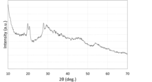
- 1 is an XRD chart of a positive electrode composite material produced in Example 2.
- 1 shows XRD charts of sulfur, titanium disulfide, positive electrode active material B, and positive electrode active material C.
- 1 is an XRD chart of sulfide solid electrolyte powder D.
- 1 is an XRD chart of a positive electrode composite material produced in Example 3.
- 1 is an XRD chart of the positive electrode composite material produced in Example 4.
- 1 is an XRD chart of the positive electrode composite materials produced in Examples 5 to 7.
- the present embodiment The following describes an embodiment of the present invention (hereinafter, may be referred to as “the present embodiment”). Note that in this specification, the upper and lower limit values of the numerical ranges “greater than or equal to,” “less than or equal to,” and “to” are values that can be combined in any way, and the numerical values in the examples can also be used as the upper and lower limit values.
- the positive electrode composite material according to one embodiment of the present invention includes at least one of titanium sulfide TiS x (2 ⁇ x ⁇ 10) and a discharge product of the titanium sulfide (hereinafter, titanium sulfide and its discharge product may be collectively referred to as titanium polysulfide), and a sulfide solid electrolyte having a diffraction peak at 2 ⁇ of 20.1 ⁇ 0.4° in X-ray diffraction using CuK ⁇ radiation.
- the sulfide solid electrolyte is a glass ceramic having a peak at a predetermined position in powder X-ray diffraction (XRD) measurement.
- XRD powder X-ray diffraction
- the sulfide solid electrolyte used in this embodiment is a glass ceramic having a diffraction peak at 2 ⁇ of 20.1 ⁇ 0.4° in XRD measurement.
- a glass ceramic solid electrolyte is a solid electrolyte having a diffraction peak at 2 ⁇ of 20.1 ⁇ 0.4° in XRD measurement.
- the glass ceramic solid electrolyte is a material in which a peak derived from the raw material of the solid electrolyte is observed, and it does not matter whether or not there is a peak derived from the raw material of the solid electrolyte.
- the glass ceramic solid electrolyte includes a crystal structure derived from the solid electrolyte
- the glass ceramic solid electrolyte may have a crystal structure partly derived from the solid electrolyte, or the whole of the crystal structure may be derived from the solid electrolyte.
- the glass ceramic solid electrolyte may contain a non-crystalline component (also called a "glass component").
- the material includes so-called glass ceramics, which are obtained by heating an amorphous solid electrolyte (glass component) to a temperature equal to or higher than the crystallization temperature.
- the sulfide solid electrolyte contains lithium, phosphorus, sulfur, and halogen as constituent elements.
- the halogen (X) preferably contains one or more selected from fluorine (F), chlorine (Cl), bromine (Br), and iodine (I), and more preferably contains Br or I.
- the halogen (X) preferably contains I.
- the types and molar ratios of the constituent elements of the sulfide solid electrolyte can be confirmed, for example, by an ICP emission spectrometer.
- the molar ratio of the constituent elements of the sulfide solid electrolyte can be adjusted by controlling the raw material composition. Note that the molar ratio of the constituent elements in the raw materials is approximately equal to the molar ratio of the constituent elements of the resulting sulfide solid electrolyte.
- the sulfide solid electrolyte of this embodiment can be produced, for example, by mixing and grinding the starting materials of a known lithium ion sulfide solid electrolyte so that the molar ratio of the constituent elements satisfies a predetermined range, vitrifying the mixture, and then converting it into a ceramic by heat treatment.
- raw materials for sulfide solid electrolytes two or more compounds or simple substances containing lithium, phosphorus, sulfur, and halogens as constituent elements can be used in combination, and there are no particular restrictions on which can be used as long as they exhibit ionic conductivity due to the metal atoms contained therein.
- Examples of the raw material containing lithium (Li) include lithium compounds such as lithium sulfide (Li 2 S), lithium oxide (Li 2 O), and lithium carbonate (Li 2 CO 3 ), and lithium metal alone. Among these, lithium compounds are preferred, and lithium sulfide is more preferred.
- the lithium sulfide can be used without any particular restrictions, but high purity lithium sulfide is preferred.
- Lithium sulfide can be produced, for example, by the methods described in JP-A-7-330312, JP-A-9-283156, JP-A-2010-163356, and JP-A-2011-84438.
- lithium hydroxide and hydrogen sulfide are reacted in a hydrocarbon organic solvent at 70°C to 300°C to produce lithium hydrosulfide, and then this reaction liquid is dehydrosulfided to synthesize lithium sulfide (JP Patent Publication 2010-163356).
- lithium hydroxide and hydrogen sulfide can be reacted in an aqueous solvent at 10°C to 100°C to produce lithium hydrosulfide, and then this reaction liquid can be dehydrosulfidized to synthesize lithium sulfide (JP Patent Publication 2011-84438).
- raw materials containing phosphorus include phosphorus sulfides such as diphosphorus trisulfide (P 2 S 3 ) and diphosphorus pentasulfide (P 2 S 5 ), phosphorus compounds such as sodium phosphate (Na 3 PO 4 ), and elemental phosphorus.
- phosphorus sulfide is preferred, and diphosphorus pentasulfide (P 2 S 5 ) is more preferred.
- Phosphorus compounds such as diphosphorus pentasulfide (P 2 S 5 ) and elemental phosphorus can be used without any particular limitation as long as they are industrially manufactured and sold.
- the raw material containing a halogen (X) preferably contains, for example, a halogen compound represented by the following formula: M l -X m
- M represents sodium (Na), lithium (Li), boron (B), aluminum (Al), silicon (Si), phosphorus (P), sulfur (S), germanium (Ge), arsenic (As), selenium (Se), tin (Sn), antimony (Sb), tellurium (Te), lead (Pb), bismuth (Bi), or any of these elements bound to oxygen or sulfur, with lithium (Li) or phosphorus (P) being preferred, and lithium (Li) being more preferred.
- X is a halogen element selected from fluorine (F), chlorine (Cl), bromine (Br), and iodine (I).
- l is an integer of 1 or 2
- m is an integer of 1 to 10.
- Xs may be the same or different.
- SiBrCl3 described later, m is 4, and Xs are composed of different elements, Br and Cl.
- halogen compounds represented by the above formula include sodium halides such as NaI, NaF, NaCl, and NaBr; lithium halides such as LiF, LiCl, LiBr, and LiI; boron halides such as BCl 3 , BBr 3 , and BI 3 ; aluminum halides such as AlF 3 , AlBr 3 , AlI 3 , and AlCl 3 ; silicon halides such as SiF 4 , SiCl 4 , SiCl 3 , Si 2 Cl 6 , SiBr 4 , SiBrCl 3 , SiBr 2 Cl 2 , and SiI 4 ; phosphorus halides such as PF 3 , PF 5 , PCl 3 , PCl 5 , POCl 3 , PBr 3 , POBr 3 , PI 3 , P 2 Cl 4 , and P 2 I 4 ; and SF 2 , SF 4 .
- sodium halides such as NaI, NaF, NaC
- sulfur halides such as SF6 , S2F10 , SCl2 , S2Cl2 , S2Br2 ; germanium halides such as GeF4 , GeCl4 , GeBr4 , GeI4, GeF2 , GeCl2 , GeBr2 , GeI2 ; arsenic halides such as AsF3 , AsCl3 , AsBr3 , AsI3 , AsF5 ; selenium halides such as SeF4 , SeF6 , SeCl2 , SeCl4 , Se2Br2 , SeBr4 ; SnF4 , SnCl4 , SnBr4 , SnI4 , SnF2 , SnCl2 tin halides such as SnBr2 , SnI2 , etc.; antimony halides such as SbF3 , SbCl3 , SbBr3 , Sb
- lithium halides such as lithium chloride (LiCl), lithium bromide (LiBr), and lithium iodide (LiI)
- phosphorus halides such as phosphorus pentachloride ( PCl5 ), phosphorus trichloride ( PCl3 ), phosphorus pentabromide ( PBr5 ), and phosphorus tribromide ( PBr3 ).
- lithium halides such as LiCl, LiBr, and LiI
- PBr3 more preferred are lithium halides such as LiCl, LiBr, and LiI, and more preferred are LiI and LiBr.
- the halogen compound may be one of the above compounds, or two or more of them may be used in combination. In other words, at least one of the above compounds can be used.
- the raw material contains a lithium compound, a phosphorus compound, and one or more halogen compounds, and it is preferable that at least one of the lithium compound and the phosphorus compound contains elemental sulfur, and it is more preferable that the raw material is a combination of lithium sulfide, phosphorus sulfide, and one or more lithium halides.
- the molar ratio of lithium sulfide to diphosphorus pentasulfide in the input raw materials is preferably 65-85:15-35, more preferably 70-80:20-30, even more preferably 72-78:22-28, and particularly preferably 75:25.
- the total content of lithium sulfide and diphosphorus pentasulfide ([Li 2 S + P 2 S 5 ] ⁇ 100/[Li 2 S + P 2 S 5 + LiX]) is preferably 60 to 95 mol%, more preferably 65 to 90 mol%, and even more preferably 70 to 85 mol%.
- the lithium content of the sulfide solid electrolyte relative to all constituent elements is 35 to 45 mol%.
- this is a positive electrode mixture that can produce a battery with a large discharge capacity, even though the lithium content is lower than that of a solid electrolyte having an argyrodite crystal structure.
- mechanical stress is applied to the raw materials to cause a reaction and produce an intermediate (glass-like powder).
- applying mechanical stress means mechanically applying shear force, impact force, etc.
- grinders such as planetary ball mills, vibration mills, and tumbling mills, and kneaders. Strong mechanical stress is applied to grind and mix the raw powder until at least a portion of it can no longer maintain its crystallinity.
- the rotation speed may be several tens to several hundreds of revolutions per minute, and the processing time may be 0.5 to 100 hours. More specifically, in the case of the planetary ball mill (manufactured by Fritsch: model number P-7) used in the examples of the present application, the rotation speed of the planetary ball mill is preferably 100 rpm or more and 500 rpm or less, and more preferably 150 rpm or more and 450 rpm or less.
- balls serving as grinding media are used, for example, zirconia balls, their diameter is preferably 0.2 to 20 mm.
- the temperature during pulverization is not particularly specified, but it is preferably 200° C. or lower in order to prevent the solid electrolyte itself from crystallizing and hardening.
- the intermediate produced by pulverization and mixing is heat-treated. Specifically, the intermediate is subjected to differential thermal and thermogravimetric simultaneous analysis (TGDTA) at a temperature rise of 10 ° C./min using a differential thermal and thermogravimetric simultaneous analysis device (TGDTA device), and the heating temperature is preferably set to 5 ° C. or less, more preferably 10 ° C. or less, and even more preferably 15 ° C. or less, starting from the temperature (T c1 ) of the top of the exothermic peak observed on the lowest temperature side. There is no particular limit to the lower limit, but the temperature may be about ⁇ 10 ° C. or more of the top of the exothermic peak observed on the lowest temperature side. By setting the temperature range as described above, the sulfide solid electrolyte (glass ceramic solid electrolyte) used in this embodiment can be obtained more efficiently.
- TTDTA differential thermal and thermogravimetric simultaneous analysis
- the heating temperature for obtaining the glass ceramic solid electrolyte of this embodiment cannot be generally defined, but is usually preferably 250°C or less, more preferably 225°C or less, and even more preferably 200°C or less. There is no particular lower limit, but it is preferably 100°C or more, more preferably 110°C or more, and even more preferably 120°C or more.
- the heating time is not particularly limited as long as it is a time that can obtain the desired glass ceramic solid electrolyte, but for example, 10 minutes or more is preferable, 30 minutes or more is more preferable, 60 minutes or more is even more preferable, and 2 hours or more is even more preferable.
- the upper limit of the heating time is not particularly limited, but 10 hours or less is preferable, 8 hours or less is more preferable, 6 hours or less is even more preferable, and 4 hours or less is even more preferable.
- the heat treatment atmosphere is not particularly limited, and may be in a hydrogen sulfide stream, in an inert gas atmosphere such as nitrogen or argon, or in a vacuum atmosphere.
- titanium sulfide TiS x (2 ⁇ x ⁇ 10) The titanium sulfide is not particularly limited, and known substances can be used. Specifically, titanium sulfide produced by mixing and pulverizing crystalline TiS2 and sulfur as raw materials by a mechanical milling method, as disclosed in Patent Document 1, can be mentioned.
- the titanium sulfide is amorphous or crystalline.
- the crystalline titanium sulfide has a diffraction peak at 2 ⁇ of 34 ⁇ 1° in X-ray diffraction using CuK ⁇ radiation, and one or more diffraction peaks at 2 ⁇ selected from 15.5 ⁇ 1°, 44 ⁇ 1°, and 54 ⁇ 1°.
- the synthesis of titanium sulfide will be described later.
- Titanium sulfide is partially or entirely converted into a discharge product during a battery reaction. Therefore, in one embodiment, titanium sulfide discharge products are present in the positive electrode mixture (positive electrode).
- An example of a discharge product of titanium sulfide is a substance containing Li as an element, which is formed by lithiating titanium sulfide.
- the positive electrode mixture preferably further contains a conductive assistant.
- the conductive assistant may be any material that has electron conductivity.
- the conductive assistant preferably has a large specific surface area with a plurality of pores.
- a carbon material having pores is particularly preferable. Carbon materials have high conductivity and are lighter than other conductive materials, so that the output density and electric capacity per unit weight of the battery can be increased.
- the specific surface area of the conductive assistant is preferably 0.1 m 2 /g or more and 5000 m 2 /g or less, more preferably 1 m 2 /g or more and 4000 m 2 /g or less, even more preferably 1 m 2 /g or more and 3000 m 2 /g or less, and most preferably 10 m 2 /g or more and 3000 m 2 /g or less.
- the pore volume of the conductive assistant is preferably 0.1 cc/g or more and 5.0 cc/g or less.
- the pores in the conductive assistant preferably have an average diameter of 0.1 nm or more and 40 nm or less, more preferably 0.5 nm or more and 40 nm or less, even more preferably 0.5 nm or more and 20 nm or less, and most preferably 1 nm or more and 20 nm or less.
- the specific surface area, pore volume, and pore diameter of the conductive assistant can be determined using a nitrogen adsorption isotherm obtained by adsorbing nitrogen gas to the conductive assistant at liquid nitrogen temperature.
- the specific surface area can be calculated by the Brenauer-Emmet-Telle (BET) multipoint method using the nitrogen adsorption isotherm.
- the pore volume and pore diameter can be determined by the Barret-Joyner-Halenda (BJH) method using the nitrogen adsorption isotherm.
- the measurement can be performed using, for example, a specific surface area/pore distribution measuring device (Autosorb-3) manufactured by Quantacrome.
- Carbon materials include, but are not limited to, carbon blacks such as Ketjen black, acetylene black, denka black, thermal black, and channel black, mesoporous carbon, activated carbon, amorphous carbon, carbon nanotubes, vapor-grown carbon fiber (VGCF), and carbon nanohorns, while conductive carbon materials include fullerene, carbon fiber, natural graphite, artificial graphite, graphene, graphene oxide, and reduced graphene oxide. Of these, activated carbon is preferred. These may be used alone or in combination of two or more. Composites of these may also be used.
- carbon blacks such as Ketjen black, acetylene black, denka black, thermal black, and channel black
- mesoporous carbon activated carbon
- amorphous carbon carbon nanotubes
- VGCF vapor-grown carbon fiber
- carbon nanohorns include fullerene, carbon fiber, natural graphite, artificial graphite, graphene, graphene oxide, and reduced graphene oxide.
- the titanium sulfide content a, the sulfide solid electrolyte content b, and the conductive assistant content c in the positive electrode mixture satisfy the following formulas (1) to (3). 10 mass% ⁇ a ⁇ 90 mass% (1) 0 mass% ⁇ b ⁇ 65 mass% (2) 0 mass% ⁇ c ⁇ 40 mass% (3) (a+b+c is 100% by mass.)
- the content a of titanium sulfide is more preferably 30% by mass or more, further preferably 60% by mass or more. Also, it is more preferably 85% by mass or less.
- the content b of the sulfide solid electrolyte is more preferably 10 mass % or more, further preferably 15 mass % or more, and more preferably 50 mass % or less.
- the content c of the conductive additive is more preferably 30% by mass or less, further preferably 10% by mass or less, and may be 0% by mass. In other words, a high-performance positive electrode mixture can be obtained without using a conductive additive.
- the positive electrode mixture may or may not contain other components in addition to the titanium polysulfide, the sulfide solid electrolyte, and the conductive additive described above.
- the other components are not particularly limited, but may include, for example, a binder, a solvent, and a dispersant.
- the positive electrode mixture according to this embodiment can be produced, for example, by the method described below.
- a method for producing a positive electrode composite according to one embodiment of the present invention includes a step of mixing titanium sulfide TiS x (2 ⁇ x ⁇ 10) that satisfies the following (A) and a sulfide solid electrolyte that satisfies the following (B).
- B In X-ray diffraction using CuK ⁇ radiation, it has a diffraction peak with a 2 ⁇ of 20.1 ⁇ 0.4°.
- (A) above means that the titanium sulfide contains titanium disulfide crystals.
- (B) above means that the sulfide solid electrolyte is a specified glass ceramic.
- a positive electrode composite that can be used to obtain a lithium ion battery with a large discharge capacity can be produced.
- the synthesis of the titanium sulfide comprises mechanically mixing sulfur with titanium disulfide (TiS 2 ).
- TiS2 used as a raw material, and any commercially available TiS2 can be used. In particular, it is preferable to use TiS2 with high purity.
- sulfur used as the raw material, and any crystalline sulfur can be used as long as it is solid at room temperature and normal pressure.
- the ratio of TiS2 to sulfur is set to be the same as the elemental ratio of titanium to sulfur in the desired titanium polysulfide.
- the x in TiSx is preferably 3 or more or 4 or more, and preferably 9 or less or 8 or less. More preferably, TiSx is mixed so that the x in TiSx is 4 to 6.
- the mechanical milling method can be carried out by mixing and grinding the raw materials using a mechanical grinding device such as a ball mill, a rod mill, a vibration mill, a disk mill, a hammer mill, a jet mill, or a VIS mill.
- a mechanical grinding device such as a ball mill, a rod mill, a vibration mill, a disk mill, a hammer mill, a jet mill, or a VIS mill.
- the material is treated to a state where a small amount of fine crystals of TiS 2 remain without proceeding to complete amorphization.
- the crystalline state of TiS 2 can be confirmed by the position and half-width of the diffraction peak by XRD measurement.
- an active material-conductive additive composite material may be formed from the titanium sulfide and conductive additive described above, and then the sulfide solid electrolyte and the active material-conductive additive composite material may be mechanically mixed.
- the active material or the active material-conductive additive composite material and the sulfide solid electrolyte are mechanically mixed to form a positive electrode mixture. This process may result in some of the active material, the active material-conductive additive composite material, and the sulfide solid electrolyte being pulverized.
- the rotation speed of the planetary ball mill is preferably 50 rpm or more and 500 rpm or less, and more preferably 80 rpm or more and 400 rpm or less.
- balls serving as grinding media for example, zirconia balls, their diameter is preferably 0.2 to 20 mm.
- the sulfide solid electrolyte has an average particle size of 10 ⁇ m or less. This allows sufficient ion conduction paths to be formed in the positive electrode, resulting in a battery with a large discharge capacity.
- the average particle size is more preferably 6 ⁇ m or less, and particularly preferably 3 ⁇ m or less.
- the average particle size means the median diameter (d50).
- the titanium sulfide content a, the sulfide solid electrolyte content b, and the conductive assistant content c in the positive electrode mixture are preferably adjusted to satisfy the following formulas (1) to (3). 10 mass% ⁇ a ⁇ 90 mass% (1) 0 mass% ⁇ b ⁇ 65 mass% (2) 0 mass% ⁇ c ⁇ 40 mass% (3) (a+b+c is 100% by mass.) By satisfying the formulas (1) to (3), a battery having a larger discharge capacity can be obtained.
- Positive electrode and lithium ion battery The positive electrode or lithium ion battery according to one embodiment of the present invention includes the positive electrode mixture of the present invention described above.
- a solid electrolyte can be used instead of a liquid electrolyte to produce an all-solid-state lithium ion battery.
- an all-solid-state lithium ion battery with a large discharge capacity can be produced.
- An all-solid-state lithium ion battery mainly consists of a positive electrode layer, a negative electrode layer, and an electrolyte layer, and the positive electrode mixture of the present invention is suitable as a constituent material of the positive electrode layer.
- the negative electrode layer and the electrolyte layer can be manufactured by a known method.
- a current collector In addition to the positive electrode layer, the negative electrode layer, and the electrolyte layer, it is preferable to use a current collector, and a known current collector is also used.
- the solid electrolyte is not particularly limited, and any known solid electrolyte can be used.
- X-ray diffraction (XRD) measurement The properties of the sample and the presence or absence of diffraction peaks were analyzed by powder XRD measurement. If there were no diffraction peaks or only peaks derived from the raw materials, the sample was judged to be amorphous, and if there were diffraction peaks other than those from the raw materials, the sample was judged to be crystalline. Specifically, the sample powder was filled into a groove having a diameter of 20 mm and a depth of 0.2 mm, and the sample was smoothed with glass. The sample was sealed with a Kapton film for XRD and measured without being exposed to air.
- the XRD measurement was carried out using a powder X-ray diffraction measurement device D2 PHASER manufactured by BRUKER Corporation under the following measurement conditions.
- Tube voltage 30 kV
- Tube current 10mA
- X-ray wavelength Cu-K ⁇ ray (1.5418 ⁇ )
- Optical system focusing method
- Slit configuration Soller slit 4° (both incident and receiving sides), divergence slit 1 mm, K ⁇ filter (Ni plate 0.5%), air scatter screen 3 mm)
- Example 1 Preparation of Positive Electrode Active Material Powder (Titanium Sulfide)
- TiS 2 titanium disulfide
- S sulfur
- the pot was placed in a planetary ball mill (Fritsche P7 Classic Line), and mechanical milling was performed at 510 rpm for 50 hours to obtain a positive electrode active material powder A.
- FIG. 1 shows an XRD chart of the positive electrode mixture (Example 1).
- All-solid-state lithium-ion battery In the method for producing an all-solid-state lithium-ion battery, a positive electrode mixture was used for the working electrode, a sulfide-based solid electrolyte A was used for the electrolyte layer, and a lithium-indium alloy was used for the counter electrode.
- the positive electrode mixture used for the working electrode was 5 mg.
- Comparative Example 1 (1) Preparation of sulfide solid electrolyte In a glove box with an argon atmosphere, 4.1414 g of lithium sulfide, 4.1739 g of diphosphorus pentasulfide, and 1.7514 g of lithium chloride were sealed in a 250 mL zirconia pot together with 40 zirconia balls having a diameter of 10 mm. The pot was placed in a planetary ball mill (Fritsche P5 Classic Line), and mechanical milling was performed at 220 rpm for 40 hours. The obtained powder was heated at 430°C for 2 hours. The resultant was pulverized in a mortar and then collected through a sieve with a mesh size of 100 ⁇ m.
- the sulfide solid electrolyte powder B (electrolyte B).
- the sulfide solid electrolyte powder B was an argyrodite-type sulfide solid electrolyte.
- FIG. 2 shows the results of XRD measurement of the positive electrode composite material prepared in Comparative Example 1.
- Comparative Example 2 (1) Preparation of sulfide solid electrolyte
- 0.5742 g of lithium sulfide and 0.9258 g of diphosphorus pentasulfide were sealed in a 45 mL zirconia pot together with 10 zirconia balls having a diameter of 10 mm.
- the pot was placed in a ball mill (Fritsche P7 Classic Line), and mechanical milling was performed at 370 rpm for 40 hours to obtain sulfide solid electrolyte powder C.
- the sulfide solid electrolyte powder C had an ionic conductivity of 0.32 mScm ⁇ 1 and an average particle size d50 of 6 ⁇ m.
- FIG. 1 shows an XRD chart of the positive electrode mixture (Comparative Example 2).
- Comparative Example 1 sulfide solid electrolyte powder B (argyrodite-type sulfide solid electrolyte) having ionic conductivity equivalent to that of sulfide solid electrolyte powder A (glass ceramic) used in Example 1 was used. In Comparative Example 2, sulfide solid electrolyte powder C (glass) having a similar ratio of Li atoms was used. As a result, it was confirmed that the discharge capacity per gram of the positive electrode composite of the all-solid-state lithium ion battery of Example 1 was large.
- the sulfide solid electrolyte powder C has lower lithium ion conductivity than the sulfide solid electrolyte powder A (glass ceramic) and has a large lithium ion conduction resistance in the positive electrode mixture, which resulted in the smaller battery capacity.
- sulfide solid electrolyte powder B argyrodite-type sulfide solid electrolyte
- the capacity was smaller.
- TiS x titanium polysulfide
- the crystalline solid electrolyte having an Argyrodite type crystal structure is composed of only crystalline components. Therefore, when stress is applied by the composite with TiS x , the impact is uniformly applied to the entire solid electrolyte particle, and the stress increases, causing the solid electrolyte particle to crack and the particle size to become smaller.
- the crystalline solid electrolyte having an Argyrodite type crystal structure with a reduced particle size is in sufficient contact with TiS x when composited, so that the reactivity is increased and lithium ions are supplied to TiS x.
- the crystalline solid electrolyte having an Argyrodite type crystal structure is likely to lead to an increase in reactivity and a decrease in lithium ion conductivity due to the supply of lithium ions to TiS x due to the large proportion of Li element , which increases the reactivity and is thought to increase the lithium ion conduction resistance in the positive electrode composite, resulting in a decrease in discharge capacity.
- the glass ceramic solid electrolyte contains a glass component, even if stress is applied by the composite with TiS x , the glass component is distorted, so the increase in stress is suppressed, and the particle size of the solid electrolyte is maintained. As a result, compared to the case of a crystalline solid electrolyte having an Argyrodite-type crystal structure, the glass ceramic solid electrolyte does not come into sufficient contact with TiS x , so lithium ions are not easily supplied to TiS x , and lithium ion conductivity does not decrease.
- the glass ceramic solid electrolyte suppresses the decrease in lithium ion conductivity and increases the discharge capacity compared to the crystalline solid electrolyte having an Argyrodite-type crystal structure.
- Example 2 (1) Preparation of Positive Electrode Composite A positive electrode composite was obtained in the same manner as in Example 1, except that the mass ratio of the positive electrode active material powder A to acetylene black was changed to 87:13 to obtain a composite of the positive electrode active material and a conductive additive, and the mass ratio of the sulfide solid electrolyte powder A to the composite of the active material and a conductive additive was changed to 25:75.
- FIG. 3 shows an XRD chart of the positive electrode composite material prepared in Example 2.
- Example 3 (1) Preparation of Positive Electrode Active Material Powder (Titanium Sulfide) Positive electrode active material powder B was obtained in the same manner as in Example 1(1) except that the time of the mechanical milling treatment was changed to 5 hours. 4 shows an XRD chart of the positive electrode active material B (MM treated for 5 hours), as well as XRD charts of the positive electrode active material C (MM treated for 1 hour), sulfur (S), and titanium disulfide (TiS 2 ), which will be described later.
- sulfide solid electrolyte powder D had an ionic conductivity of 2.9 mScm ⁇ 1 and an average particle size d50 of 2 ⁇ m.
- FIG. 6 shows an XRD chart of the positive electrode composite material produced in Example 3.
- Example 4 Preparation of Positive Electrode Composite A positive electrode composite was obtained in the same manner as in Example 3, except that the sulfide solid electrolyte powder A was used instead of the sulfide solid electrolyte powder D.
- FIG. 7 shows an XRD chart of the positive electrode composite material prepared in Example 4.
- Example 5 Preparation of Positive Electrode Active Material Powder (Titanium Sulfide) Positive electrode active material powder C was obtained in the same manner as in Example 1(1) except that the time for the mechanical milling treatment was changed to 1 hour.
- Example 6 (1) Preparation of Positive Electrode Composite Positive electrode active material powder C and sulfide solid electrolyte powder D were weighed out to a mass ratio of 75:25, and were enclosed in a 45 mL zirconia pot together with 100 zirconia balls having a diameter of 5 mm. The pot was placed in a planetary ball mill (Fritsche P7 Classic Line), and the mixture was mixed at 100 rpm for 30 minutes to obtain a positive electrode composite.
- planetary ball mill Feritsche P7 Classic Line
- Example 7 (1) Preparation of Positive Electrode Composite Positive electrode active material powder C and acetylene black were weighed out so that the mass ratio was 90:10, and mixed for 5 minutes using an agate mortar. The obtained powder was sealed in a 45 mL zirconia pot together with 100 zirconia balls having a diameter of 5 mm, and mixed in a planetary ball mill (Fritsche P7 Classic Line) at 370 rpm for 1 hour to obtain a composite of the positive electrode active material and the conductive assistant.
- a planetary ball mill Feritsche P7 Classic Line
- the sulfide solid electrolyte powder D was added to the pot so that the mass ratio of the composite of the positive electrode active material and the conductive assistant (solid electrolyte powder D:composite) was 17:83, and the mixture was further mixed in a planetary ball mill at 100 rpm for 30 minutes to obtain a positive electrode composite.
- Example 8 (1) Preparation of Positive Electrode Active Material Powder (Titanium Sulfide) In a glove box under an argon atmosphere, titanium disulfide (TiS 2 ) powder and sulfur (S) powder were weighed out so that the molar ratio was 1:4, and were sealed in a 45 mL zirconia pot together with 90 g of zirconia balls having a diameter of 4 mm. The pot was placed in a planetary ball mill (Fritsche P7 Classic Line), and mechanical milling was performed at 510 rpm for 1 hour to obtain a positive electrode active material powder D.
- (2) Preparation of Positive Electrode Mixture A positive electrode mix was obtained in the same manner as in Example 7, except that the positive electrode active material powder D obtained in (1) above was used.
- the positive electrode composite of the present invention is suitable as a structural material for lithium ion batteries.
- the lithium ion battery of the present invention is also suitable for use in, for example, information-related devices and communication devices such as personal computers, video cameras, and mobile phones, and in vehicles such as electric cars.
Landscapes
- Chemical & Material Sciences (AREA)
- Engineering & Computer Science (AREA)
- Chemical Kinetics & Catalysis (AREA)
- Electrochemistry (AREA)
- General Chemical & Material Sciences (AREA)
- Inorganic Chemistry (AREA)
- Materials Engineering (AREA)
- Manufacturing & Machinery (AREA)
- Condensed Matter Physics & Semiconductors (AREA)
- General Physics & Mathematics (AREA)
- Physics & Mathematics (AREA)
- Secondary Cells (AREA)
- Conductive Materials (AREA)
Priority Applications (3)
| Application Number | Priority Date | Filing Date | Title |
|---|---|---|---|
| CN202480021735.4A CN120981931A (zh) | 2023-03-29 | 2024-03-21 | 正极复合材料、正极复合材料的制造方法及锂离子电池 |
| KR1020257027453A KR20250164693A (ko) | 2023-03-29 | 2024-03-21 | 정극 합재, 정극 합재의 제조 방법 및 리튬 이온 전지 |
| JP2025510626A JPWO2024203694A1 (https=) | 2023-03-29 | 2024-03-21 |
Applications Claiming Priority (2)
| Application Number | Priority Date | Filing Date | Title |
|---|---|---|---|
| JP2023-053718 | 2023-03-29 | ||
| JP2023053718 | 2023-03-29 |
Publications (1)
| Publication Number | Publication Date |
|---|---|
| WO2024203694A1 true WO2024203694A1 (ja) | 2024-10-03 |
Family
ID=92904962
Family Applications (1)
| Application Number | Title | Priority Date | Filing Date |
|---|---|---|---|
| PCT/JP2024/010947 Ceased WO2024203694A1 (ja) | 2023-03-29 | 2024-03-21 | 正極合材、正極合材の製造方法及びリチウムイオン電池 |
Country Status (4)
| Country | Link |
|---|---|
| JP (1) | JPWO2024203694A1 (https=) |
| KR (1) | KR20250164693A (https=) |
| CN (1) | CN120981931A (https=) |
| WO (1) | WO2024203694A1 (https=) |
Citations (3)
| Publication number | Priority date | Publication date | Assignee | Title |
|---|---|---|---|---|
| JP2006236993A (ja) * | 2005-01-31 | 2006-09-07 | Matsushita Electric Ind Co Ltd | 熱電池 |
| JP2019040752A (ja) * | 2017-08-25 | 2019-03-14 | 株式会社サムスン日本研究所 | 全固体型二次電池 |
| JP2020064864A (ja) * | 2013-09-02 | 2020-04-23 | 三菱瓦斯化学株式会社 | 全固体電池および電極活物質の製造方法 |
Family Cites Families (1)
| Publication number | Priority date | Publication date | Assignee | Title |
|---|---|---|---|---|
| JP5991618B2 (ja) | 2012-11-05 | 2016-09-14 | 国立研究開発法人産業技術総合研究所 | リチウム二次電池用正極活物質 |
-
2024
- 2024-03-21 WO PCT/JP2024/010947 patent/WO2024203694A1/ja not_active Ceased
- 2024-03-21 KR KR1020257027453A patent/KR20250164693A/ko active Pending
- 2024-03-21 CN CN202480021735.4A patent/CN120981931A/zh active Pending
- 2024-03-21 JP JP2025510626A patent/JPWO2024203694A1/ja active Pending
Patent Citations (3)
| Publication number | Priority date | Publication date | Assignee | Title |
|---|---|---|---|---|
| JP2006236993A (ja) * | 2005-01-31 | 2006-09-07 | Matsushita Electric Ind Co Ltd | 熱電池 |
| JP2020064864A (ja) * | 2013-09-02 | 2020-04-23 | 三菱瓦斯化学株式会社 | 全固体電池および電極活物質の製造方法 |
| JP2019040752A (ja) * | 2017-08-25 | 2019-03-14 | 株式会社サムスン日本研究所 | 全固体型二次電池 |
Also Published As
| Publication number | Publication date |
|---|---|
| CN120981931A (zh) | 2025-11-18 |
| KR20250164693A (ko) | 2025-11-25 |
| JPWO2024203694A1 (https=) | 2024-10-03 |
Similar Documents
| Publication | Publication Date | Title |
|---|---|---|
| JP7258089B2 (ja) | 硫化物固体電解質 | |
| JP7187637B2 (ja) | 硫化物固体電解質の製造方法 | |
| JP7625556B2 (ja) | 硫化物固体電解質の製造方法 | |
| KR102319569B1 (ko) | 황화물 고체 전해질 | |
| JP7329062B2 (ja) | 固体電解質、電極合剤及び電池 | |
| JP7584205B2 (ja) | 固体電解質及びその製造方法 | |
| CN111448702A (zh) | 硫化物系化合物颗粒、固体电解质和锂二次电池 | |
| JPWO2018164224A1 (ja) | 硫化物固体電解質粒子 | |
| CN112203975B (zh) | 硫化物固体电解质和电池 | |
| KR102910872B1 (ko) | 황화물 고체 전해질, 및 그것을 사용한 전극 합제, 고체 전해질층 그리고 전지 | |
| JP7570498B2 (ja) | 固体電解質 | |
| WO2018216730A1 (ja) | 硫化物固体電解質 | |
| WO2018003333A1 (ja) | リチウム二次電池用硫化物系固体電解質 | |
| JP7796724B2 (ja) | 固体電解質及びその製造方法 | |
| WO2024034499A1 (ja) | 正極合材、正極合材の製造方法及びリチウムイオン電池 | |
| JP7505135B2 (ja) | 複合材料及びその製造方法 | |
| CN118020188A (zh) | 硫化物系固体电解质 | |
| JP7301005B2 (ja) | 硫化物系固体電解質及び全固体リチウムイオン電池 | |
| WO2024203694A1 (ja) | 正極合材、正極合材の製造方法及びリチウムイオン電池 | |
| WO2024190440A1 (ja) | 正極合材、正極合材の製造方法及びリチウムイオン電池 | |
| WO2024190765A1 (ja) | 正極合材、正極合材の製造方法及びリチウムイオン電池 | |
| TWI914365B (zh) | 固體電解質、電極合劑及電池 | |
| WO2026034194A1 (ja) | 正極合材 | |
| WO2026034191A1 (ja) | 正極合材 | |
| WO2026034190A1 (ja) | 正極合材 |
Legal Events
| Date | Code | Title | Description |
|---|---|---|---|
| 121 | Ep: the epo has been informed by wipo that ep was designated in this application |
Ref document number: 24779816 Country of ref document: EP Kind code of ref document: A1 |
|
| ENP | Entry into the national phase |
Ref document number: 2025510626 Country of ref document: JP Kind code of ref document: A |
|
| WWE | Wipo information: entry into national phase |
Ref document number: 2025510626 Country of ref document: JP |
|
| ENP | Entry into the national phase |
Ref document number: 1020257027453 Country of ref document: KR Free format text: ST27 STATUS EVENT CODE: A-0-1-A10-A15-NAP-PA0105 (AS PROVIDED BY THE NATIONAL OFFICE) |
|
| NENP | Non-entry into the national phase |
Ref country code: DE |
|
| 122 | Ep: pct application non-entry in european phase |
Ref document number: 24779816 Country of ref document: EP Kind code of ref document: A1 |