WO2024203394A1 - 画像撮影方法、x線タルボ撮影装置、画像撮影システム及びプログラム - Google Patents
画像撮影方法、x線タルボ撮影装置、画像撮影システム及びプログラム Download PDFInfo
- Publication number
- WO2024203394A1 WO2024203394A1 PCT/JP2024/010024 JP2024010024W WO2024203394A1 WO 2024203394 A1 WO2024203394 A1 WO 2024203394A1 JP 2024010024 W JP2024010024 W JP 2024010024W WO 2024203394 A1 WO2024203394 A1 WO 2024203394A1
- Authority
- WO
- WIPO (PCT)
- Prior art keywords
- image
- orientation
- ray talbot
- inspected
- ray
- Prior art date
- Legal status (The legal status is an assumption and is not a legal conclusion. Google has not performed a legal analysis and makes no representation as to the accuracy of the status listed.)
- Ceased
Links
Images





Classifications
-
- G—PHYSICS
- G01—MEASURING; TESTING
- G01N—INVESTIGATING OR ANALYSING MATERIALS BY DETERMINING THEIR CHEMICAL OR PHYSICAL PROPERTIES
- G01N23/00—Investigating or analysing materials by the use of wave or particle radiation, e.g. X-rays or neutrons, not covered by groups G01N3/00 – G01N17/00, G01N21/00 or G01N22/00
- G01N23/02—Investigating or analysing materials by the use of wave or particle radiation, e.g. X-rays or neutrons, not covered by groups G01N3/00 – G01N17/00, G01N21/00 or G01N22/00 by transmitting the radiation through the material
- G01N23/04—Investigating or analysing materials by the use of wave or particle radiation, e.g. X-rays or neutrons, not covered by groups G01N3/00 – G01N17/00, G01N21/00 or G01N22/00 by transmitting the radiation through the material and forming images of the material
- G01N23/041—Phase-contrast imaging, e.g. using grating interferometers
Definitions
- the present invention relates to an image capture method, an X-ray Talbot imaging device, an image capture system, and a program.
- analysis using Talbot photography is being carried out as a method for acquiring internal information such as fiber orientation information.
- fibers such as cellulose or aramid fibers, which have a small density difference from the resin, are used in the fiber-reinforced resin, it is not possible to obtain small-angle scattering images that are clear enough for analysis, and internal information such as orientation cannot be accurately obtained.
- Patent Document 1 proposes a technology that reduces random noise by superimposing the captured images.
- the objective of the present invention is therefore to obtain clearer orientation information through X-ray Talbot photography.
- the image capturing method of the present invention comprises the steps of: An image capturing method using an X-ray Talbot imaging device, in which a composite material having a density difference (g/cm3) between an oriented material and a resin in the range of 0.1 to 1.0 and a thickness of 0.02 mm to 20 mm is used as an inspection object, A superimposing step of superimposing a plurality of inspection objects; An imaging step of capturing X-ray Talbot images of a plurality of objects to be inspected in a superimposed state; an orientation information acquisition step of acquiring orientation information related to orientation based on the captured X-ray Talbot image; Includes.
- the X-ray Talbot imaging apparatus of the present invention comprises: An imaging means for capturing X-ray Talbot images of a plurality of objects to be inspected in a superimposed state; and an orientation information acquisition means for acquiring orientation information related to the orientation based on the captured X-ray Talbot image,
- the object to be inspected is made of a composite material having a density difference (g/cm3) between the oriented material and the resin in the range of 0.1 to 1.0 and a thickness of 0.02 mm to 20 mm.
- the image capturing system of the present invention comprises: An image capturing system including an X-ray Talbot imaging device for capturing an image of a superimposed inspection object, An imaging means for capturing X-ray Talbot images of a plurality of objects to be inspected in a superimposed state; and an orientation information acquisition means for acquiring orientation information related to the orientation based on the captured X-ray Talbot image,
- the object to be inspected is made of a composite material having a density difference (g/cm3) between the oriented material and the resin in the range of 0.1 to 1.0 and a thickness of 0.02 mm to 20 mm.
- the program of the present invention is The computer of the X-ray Talbot imaging device, an imaging control means for causing the imaging means to capture the X-ray Talbot images of the object to be inspected in a superimposed state; functioning as an orientation information acquisition means for acquiring orientation information relating to orientation based on the captured X-ray Talbot image;
- the object to be inspected is a composite material having a density difference (g/cm3) between the oriented material and the resin in the range of 0.1 to 1.0 and a thickness of 0.02 mm to 20 mm.
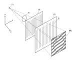
- FIG. 1 is a schematic diagram showing an overall view of an X-ray Talbot imaging device.
- FIG. 1 is a diagram illustrating the principle of a Talbot interferometer.
- 3 is a schematic plan view of a source grating, a first grating, and a second grating.
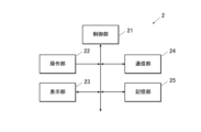
- FIG. FIG. 2 is a block diagram showing a functional configuration of the image processing device.
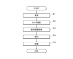
- 4 is a flowchart showing an image capturing method.
- FIG. FIG. This is an example of a small-angle scattering image. This is an example of a small-angle scattering image.
- 1 is an example of an orientation degree image.
- 1 is an example of an orientation degree image.
- 1 is a graph showing the orientation signal values.
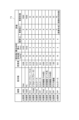
- 13 is an example of a subject and an evaluation. 13 is an example of a subject and an evaluation.
- an X-ray imaging system 100 of this embodiment includes an X-ray Talbot imaging device 1 and an image processing device 2.
- the X-ray imaging system 100 uses an X-ray Talbot imaging device 1 to rotate a subject H (object to be inspected) in a plane perpendicular to the optical axis of the X-rays, change the angle, and capture images of the subject H multiple times.
- the image processing device 2 generates a reconstructed image for each imaging angle based on the moiré images read by the X-ray Talbot imaging device 1 and a moiré image in the absence of the subject H (referred to as a BG: Back Ground moiré image).
- the X-ray imaging system 100 captures a moire image in a state in which the subject H is not present at least once before or after imaging the subject H.
- the objects to be inspected in this embodiment are composite materials (composite materials) used as components of various products, such as aerospace and aircraft-related products, automobiles, ships, fishing rods, as well as electrical, electronic, and home appliance parts, parabolic antennas, bathtubs, flooring materials, roofing materials, and the like.
- composite materials include CFRP (Carbon-Fiber-Reinforced Plastics) and CFRTP (Carbon Fiber Reinforced Plastics), which use carbon fiber or glass fiber as reinforcing fibers.
- FRPs Fiber-Reinforced Plastics
- CFRP Carbon Fiber Reinforced Thermo Plastics
- GFRP Glass Fiber Reinforced Plastics
- CMCs Ceramic Matrix Composites
- the resins used in the composite materials are, for example, general-purpose plastics, engineering plastics, and super engineering plastics, but are not limited to these.
- Resins are used as resin composite materials to which fillers having micro- or nano-sized structures are added to impart certain properties such as strength, and are often used as plastic molded products.
- Fillers include organic materials, inorganic materials, magnetic materials, and metal materials.
- composite materials such as PPS, POM, PA, PC, and PP as resins and aramid fibers, talc, and cellulose fibers as fillers may be used.
- the plastic molded product is a plastic mag
- composite materials such as nylon as resin and strontium ferrite, samarium cobalt, and the like may be used as fillers.
- the composite materials that are the subject of the above-mentioned inspections are manufactured by pouring resin into a mold (injection molding), pushing resin into a sheet (extrusion molding), melt casting, solution casting, etc.
- the X-ray Talbot imaging device 1 includes an X-ray generator 11, a source grating 12, a subject table 13, a first grating 14, a second grating 15, an X-ray detector 16, a support 17, and a base unit 18.
- the various components of the X-ray Talbot imaging device 1 function as an imaging unit that captures superimposed X-ray Talbot images of a plurality of objects to be inspected.
- the X-ray Talbot image is at least one of three types of reconstructed images (absorption image, differential phase contrast image, and small angle scattering image).
- reconstructed images At least three types of images can be reconstructed (referred to as reconstructed images) by capturing a moire image of the subject H at a predetermined position on the subject table 13 using a method based on the principles of the fringe scanning method and analyzing the moire image using the Fourier transform method.
- an absorption image (same as a normal X-ray absorption image) which visualizes the difference in average components between the BG moiré fringe image and the moiré fringe image; a differential phase image which visualizes the difference in phase between the BG moiré fringe image and the moiré fringe image; and a small-angle scattering image which visualizes the visibility rate, which is the ratio of the visibility of the BG moiré fringe image and the moiré fringe image.
- an absorption image (same as a normal X-ray absorption image) which visualizes the difference in average components between the BG moiré fringe image and the moiré fringe image
- a differential phase image which visualizes the difference in phase between the BG moiré fringe image and the moiré fringe image
- a small-angle scattering image which visualizes the visibility rate, which is the ratio of the visibility of the BG moiré fringe image and the moiré fringe image.
- the fringe scanning method is a method in which one of multiple gratings is moved in the direction of the slit period by 1/M (M is a positive integer, M>2 for absorption images, M>3 for differential phase images and small-angle scattering images) of the grating, and then reconstructed using the moiré images captured M times to obtain a high-resolution reconstructed image.
- M is a positive integer, M>2 for absorption images, M>3 for differential phase images and small-angle scattering images
- the Fourier transform method is a method in which, in the presence of a subject, a single moiré image is captured using an X-ray Talbot imaging device, and then in image processing, the moiré image is subjected to a Fourier transform or other process to reconstruct and generate an absorption image, differential phase image, and small-angle scattering image.
- Figure 2 shows the case of a Talbot interferometer
- the case of a Talbot-Lau interferometer can be basically explained in the same way.
- the z direction in Figure 2 corresponds to the vertical direction in the X-ray Talbot imaging device 1 in Figure 1
- the x and y directions in Figure 2 correspond to the horizontal directions (front-back and left-right directions) in the X-ray Talbot imaging device 1 in Figure 1.
- the first grating 14 and the second grating 15 (and the source grating 12 in the case of a Talbot-Lau interferometer) have a plurality of slits S arranged at a predetermined period d in the x direction perpendicular to the z direction, which is the irradiation direction of the X-rays.
- the periods of the source grating 12, the first grating 14, and the second grating 15 are not limited to being the same.
- X-rays irradiated from X-ray source 11a (X-ray generator 11) (in the case of a Talbot-Lau interferometer, the X-rays irradiated from X-ray source 11a are converted into multiple light sources by source grating 12 (not shown in Figure 2)) pass through first grating 14, the transmitted X-rays form images at regular intervals in the z direction. These images are called self-images (also called grating images, etc.), and the phenomenon in which self-images are formed at regular intervals in the z direction is called the Talbot effect.
- the Talbot effect is a phenomenon in which, when coherent light passes through the first grating 14, which has slits S at a constant period d as shown in Figure 2, it forms self-images at constant intervals in the direction of light travel, as described above.
- a second grating 15 having slits S with approximately the same period as the self-image of the first grating 14 is placed at the position where the self-image of the first grating 14 forms an image.
- the extension direction of the slits S of the second grating 15 i.e., the x-axis direction in FIG. 2
- a moiré image Mo is obtained on the second grating 15.
- the subject H causes the phase of the X-rays to shift or the X-rays to scatter.
- the moire fringes of the moire image Mo are disturbed at the boundary of the subject's edge, and in the latter case, the visibility rate of the scattered portion is reduced without being limited to the subject's edge.
- the subject H is not present between the X-ray source 11a (X-ray generating device 11) and the first grating 14, a moire fringe image not influenced by the subject H, that is, a BG moire image, appears.
- a moire fringe image not influenced by the subject H that is, a BG moire image.
- the subject H may be disposed behind the first grating 14 .
- the second grating 15 is arranged in the second cover unit 130 at a position where the self-image of the first grating 14 forms an image. Also, as mentioned above, if the second grating 15 and the X-ray detector 16 are separated, the moire image Mo (see FIG. 2) becomes blurred, so in this embodiment, the X-ray detector 16 is arranged directly below the second grating 15.
- the second cover unit 130 is provided to protect the X-ray detector 16, etc. by preventing people or objects from colliding with or touching the first grating 14, second grating 15, X-ray detector 16, etc.
- the X-ray detector 16 is configured such that conversion elements that generate electrical signals in response to irradiated X-rays are arranged in a two-dimensional array (matrix), and the electrical signals generated by the conversion elements are read as image signals.
- the X-ray detector 16 captures the moiré image Mo, which is an image of the X-rays formed on the second grating 15, as an image signal for each conversion element.
- the X-ray Talbot imaging device 1 captures multiple moiré images Mo using a so-called fringe scanning method. That is, in the X-ray Talbot imaging device 1 according to this embodiment, multiple moiré images Mo are captured while shifting the relative positions of the first grating 14 and the second grating 15 in the x-axis direction in Figures 1 to 3 (i.e., the direction perpendicular to the extension direction (y-axis direction) of the slit S). In another embodiment, the source grating 12 may be moved.
- the image processing device 2 receives image signals of multiple moiré images Mo from the X-ray Talbot imaging device 1, and performs image processing to reconstruct an absorption image, a differential phase image, a small-angle scattering image, etc. based on the multiple moiré images Mo.
- a moving device (not shown) is provided for moving the first grating 14 in the x-axis direction by a predetermined amount. Note that it is also possible to configure the device so that the second grating 15 is moved instead of the first grating 14, or so that both are moved. In another embodiment, the source grating 12 may be moved.
- the X-ray Talbot imaging device 1 captures only one moire image Mo while fixing the relative positions of the first grating 14 and the second grating 15. After that, the moire image Mo is analyzed by the Fourier transform method or the like in the image processing device to generate an absorption image, a differential phase image, It can also be configured to reconstruct small angle scattering images.
- a sine wave graph is a graph in which the horizontal axis represents the relative angle between the sample and the lattice, and the vertical axis represents the small-angle scattering signal value of a certain pixel. The amplitude, average, and phase of the sine wave are obtained as fitting parameters.
- orientation degree image An image showing the amplitude value for each pixel is called an orientation degree image
- an image showing the average value for each pixel is called a scattering intensity image
- an image showing the phase for each pixel is called an orientation angle image.
- the fitting method is not limited to a sine wave.
- the images (orientation degree image, scattering intensity image, and orientation angle image) generated by recombining the reconstructed images are collectively referred to as an orientation analysis image.
- the orientation analysis image is generated based on multiple small-angle scattering images captured by changing the relative angle of the subject with respect to the slits of the grid of the X-ray Talbot imaging device.
- This embodiment is a so-called vertical type, in which the X-ray generator 11, radiation source grating 12, subject table 13, first grating 14, second grating 15, and X-ray detector 16 are arranged in this order in the z direction, which is the direction of gravity. That is, in this embodiment, the z direction is the irradiation direction of X-rays from the X-ray generator 11.
- the X-ray generator 11 is equipped with an X-ray source 11a, such as a Coolidge X-ray source or a rotating anode X-ray source that are widely used in medical settings. Other X-ray sources can also be used.
- the X-ray generator 11 of this embodiment is configured to irradiate X-rays in a cone beam shape from a focal point. In other words, the X-rays are irradiated so that they spread out the further away from the X-ray generator 11.
- the radiation source grating 12 is provided below the X-ray generator 11.
- the radiation source grating 12 is not attached to the X-ray generator 11, but is attached to a fixed member 18a attached to a base portion 18 provided on a support 17.
- a buffer member 17a is provided between the X-ray generator 11 and the support 17 to prevent vibrations from the X-ray generator 11 from propagating to other parts of the X-ray Talbot imaging device 1, such as the support 17 (or to reduce the amount of vibration that propagates).
- the fixed member 18a is equipped with a filter (also called an additional filter) 112 for changing the radiation quality of the X-rays that have passed through the radiation source grating 12, an irradiation field aperture 113 for narrowing the irradiation field of the irradiated X-rays, and an irradiation field lamp 114 for irradiating the subject with visible light instead of X-rays to perform alignment before irradiating the subject with X-rays.
- a filter also called an additional filter
- a first cover unit 120 is arranged around the radiation source grating 12 and other components to protect them.
- the subject table 13 is a table on which the subject H is placed.
- the subject table 13 is provided with a fixing unit (not shown) that fixes the position of the subject H with respect to the X-rays irradiated from the X-ray generator 11.
- the fixing unit has a fixing part that can fix the subject H at a predetermined position, and a moving mechanism that can rotate the fixing part about the XY axis (two-dimensional direction) + ⁇ axis (three-dimensional direction).
- the subject H does not necessarily need to be fixed, and if the subject H is a plate material or a dumbbell test piece that does not move on the subject table 13 even without being fixed, it can be photographed without being fixed.
- the imaging angle is an angle indicating the position of the subject H with respect to the X-ray Talbot imaging device 1.
- the grating facing angle is the relationship (angle) between the direction of the captured image (or the image displayed after imaging) and the direction of the gratings (the multi-slit 12, the first grating 14, and the second grating 15).
- the amount of phase change or the degree of decrease in visibility rate varies depending on the relative angle between the grating and the boundary between materials with different refractive indices inside the subject, or between the grating and the scatterer, and when the reconstructed image is generated, the image that appears will differ depending on the angle. Therefore, by photographing the same part of the subject H multiple times while changing the grating facing angle, multiple image sets of three types of reconstructed images (absorption image, differential phase image, small-angle scattering image) based on the same moire image Mo can be obtained for each angle.
- alignment may be performed by image processing.
- the alignment may be performed using the characteristics of the subject H, or a marker for alignment other than the subject H may be photographed together with the subject H and the marker may be used.
- the imaging angle of the subject H is adjusted by the moving mechanism of the fixed unit, but a configuration may be adopted in which the X-ray source 11a, the multiple gratings 12, 14, 15 (which may be grating holders), and the X-ray detector 16 rotate as a whole around the optical axis of the X-rays, thereby enabling imaging by changing the grating facing angle between the subject H and the gratings.
- the image processing device 2 can use the moire image Mo obtained by the X-ray Talbot photography device 1 to generate three types of high-definition reconstructed images (absorption image, differential phase image, small-angle scattering image) of the subject H, generate orientation analysis images (orientation degree image, scattering intensity image, orientation angle image), and perform image processing of the obtained reconstructed images and orientation analysis images.
- the image processing device 2 is configured to include a control unit 21, an operation unit 22, a display unit 23, a communication unit 24, and a storage unit 25.
- the image processing device 2 including the display unit 23 also functions as an image display device.
- the control unit 21 is composed of a CPU (Central Processing Unit), a RAM (Random Access Memory), and the like, and executes various processes in cooperation with programs stored in the storage unit 25 .
- the control unit 21 functions as an orientation information acquisition unit that acquires orientation information related to the orientation from the captured X-ray Talbot image.
- the control unit 21 also functions as a linking unit that links characteristic information regarding the orientation of the inspection object to other characteristic information of the inspection object.
- the operation unit 22 is configured with a keyboard equipped with cursor keys, numeric input keys, various function keys, etc., and a pointing device such as a mouse, and outputs press signals of keys pressed on the keyboard and operation signals by the mouse as input signals to the control unit 21. It may also be configured to include a touch panel configured integrally with the display of the display unit 23, generate operation signals corresponding to these operations, and output them to the control unit 21.
- the display unit 23 is configured with a display such as a CRT (Cathode Ray Tube) or LCD (Liquid Crystal Display), and displays various display screens, etc., according to the display control of the control unit 21.
- a display such as a CRT (Cathode Ray Tube) or LCD (Liquid Crystal Display), and displays various display screens, etc., according to the display control of the control unit 21.
- the communication unit 24 has a communication interface and communicates with the X-ray Talbot imaging device 1 on the communication network and with external systems such as a PACS (Picture Archiving and Communication System) via wired or wireless communication.
- PACS Picture Archiving and Communication System
- the memory unit 25 is composed of a non-volatile semiconductor memory, a hard disk, etc., and stores programs executed by the control unit 21, data necessary for executing the programs, information on the object to be inspected (subject H) (subject information), characteristic information on the object to be inspected, information such as reconstructed images and orientation analysis images, etc.
- the characteristic information of the inspection object is characteristic information of the direction of the inspection object itself. Specifically, MD direction, TD direction, and ND direction are included.
- the resin flow direction when resin or the like is poured into a mold is called MD (machine direction) direction
- MD machine direction
- TD transverse direction
- ND normal direction
- MD machine direction
- TD transverse direction
- ND normal direction
- the characteristic information is linked to the information of the inspection object and stored in the storage unit 25.
- the characteristic information may also be the orientation of the inspection object and the cut-out direction of the inspection object.
- the characteristic information of the direction of the object to be inspected itself is not limited to information of the actual object, but may be characteristic information of the design direction known from mold information or CAD, CAE, or simulation of the object to be inspected.
- the image capturing method of the present invention is a method for obtaining clear orientation information by superimposing an object to be inspected (subject H) and capturing Talbot photography.
- step S1 superimposition step
- the subject H will be described.
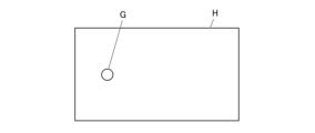
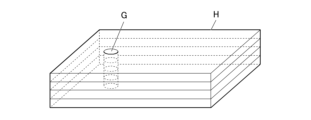
- the subject H is represented by an image diagram as shown in Fig. 6.
- the subject H is assumed to be formed by pouring resin or the like into a mold (injection molding).
- the gate G in the subject H in Fig. 6 is the position where the resin or the like is poured into the mold.
- the multiple subjects H are assumed to be produced using the same mold. Note that the mold may be capable of producing multiple subjects H in one go.
- 7 is an image diagram of four overlapping objects H by a user. For example, when viewed from a vertical direction, the user fixes the object H so that a predetermined position of the object H is located on a vertical line, and aligns the position of the gate G (fixing step).
- the position of the gate G is a position that corresponds to the gate position of the mold. This aligns the outflow direction of the resin.
- the fixing method is not limited to this, and may be any method that can align the flow direction of the resin.
- fix them using a jig, tape, clips, etc.
- the subject H may also be asymmetric or have a three-dimensional structure other than a plate-like structure. When the subject H is fixed, a space may be created depending on the three-dimensional structure, but as with a plate-like composite material, the subject H may be fixed so that a predetermined position of the subject H is positioned on a vertical line when viewed from a direction perpendicular to the subject H.
- the gate position may also be aligned using characteristic information of the object H. For example, by aligning the MD, TD, and ND directions, the object H can be overlapped so that the resin flow directions match. In addition, a destructive test is performed on a certain object H, and the flow direction of the resin is confirmed using a microscope, etc. Then, the destructive object H and an object H created under the same conditions are overlapped based on the confirmed flow direction, thereby improving the accuracy of alignment.
- an X-ray Talbot image is at least one of the three types of reconstructed images (absorption image, differential phase image, and small angle scattering image).
- the control unit 21 acquires orientation information based on the X-ray Talbot image (step S3: orientation information acquisition step). Specifically, the control unit 21 recomposes the reconstructed images, etc., to acquire an orientation degree image, an orientation angle image, etc.
- the orientation information is information regarding the direction in which a scatterer, such as a fiber contained in the subject H, faces within the subject H.
- the orientation information is an orientation degree image or an orientation angle image.
- the orientation information may be a profile of an orientation degree signal value, which will be described later.
- the orientation information is not limited to these examples, and refers to various types of information that allow a user to confirm the direction in which a scatterer faces within the subject H.
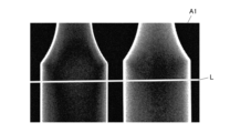
- the control unit 21 acquires an orientation degree image A1 shown in FIG. 8 as the orientation information.
- FIG. 9 shows an orientation degree image acquired by another imaging method.
- the orientation degree image A2 is an orientation degree image obtained by taking a single Talbot photograph of the subject H. In the orientation degree image A2, the signal derived from the fibers is weak, and orientation degree information cannot be confirmed.
- the orientation degree image A3 is an orientation degree image in which the contrast of the orientation degree image A2 is increased. By increasing the contrast, random noise increases.
- the orientation degree image A4 is an orientation degree image obtained by superimposing on a single image an orientation degree image obtained by Talbot photography of the subject H. Although random noise is reduced, the signal-to-noise ratio of the orientation degree information remains unchanged. It can be seen that in the orientation image A1 captured by the imaging method of the present invention, random noise is reduced and the signal-to-noise ratio of the orientation information is improved.
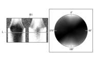
- the control unit 21 acquires an orientation angle image B1 shown in FIG. 10 as the orientation information (step S3; orientation information acquisition step).
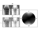
- FIG. 11 shows an orientation angle image acquired by another imaging method.
- the orientation angle image B2 is an orientation angle image obtained by Talbot photographing the subject H in one image.
- the orientation angle image B3 is an orientation angle image in which orientation angle images obtained by Talbot photography of the subject H are superimposed on one image. Even in the orientation angle image B3, the orientation angle information cannot be confirmed.
- orientation angle information can be confirmed.
- control unit 21 uses the X-ray imaging system 100 to link the orientation information to the characteristic information and store it in the storage unit 25 (step S4; linking step). This makes it possible to link the directional characteristic information of the object being inspected with the measured orientation information.
- step S5 evaluates the subject H based on the orientation information.
- An example of the evaluation will be described later with reference to Figures 13 and 14.
- FIG. 12 is used to compare the profiles of the orientation signal values obtained by different imaging methods.
- the thick line in FIG. 12 is a profile P1 of the orientation signal value on the line L of the orientation image A1 shown in FIG.
- the midline in FIG. 12 is a profile P2 of the orientation signal value on the line L of the orientation image A2 shown in FIG.
- the thin line in FIG. 12 is a profile P3 of the orientation signal value on line L of the orientation image A4 shown in FIG.
- the horizontal axis indicates the position (pixel position) on the line L.
- the vertical axis indicates the orientation signal value. Comparing profiles P1 to P3, it can be seen that the orientation signal values near positions 550 and 950 are highlighted. That is, the orientation image A1 shown in Fig. 8 has clearer signal value peaks near positions 550 and 950 compared to the orientation image A2 and orientation image A4 shown in Fig. 9.
- Example 13 and 14 are evaluation charts T1 and T2 showing the evaluation of the subject H and the results of Talbot photography.
- the resin and oriented material constituting the subject H are described.
- the density difference (g/cm3) between the resin and the oriented material is described.
- the oriented material is organic fiber.
- the organic fiber is, for example, cellulose fiber.
- ABS is styrene-acrylonitrile-butadiene
- PA6 is nylon 6
- PC is polycarbonate
- PA66 nylon 66
- PP polypropylene.
- the content of the oriented material in the object H is shown.
- the thickness of each object H is shown.
- the S and A to E in the evaluation columns indicate the relative clarity of the orientation information, and are rated as S (best), A (good), B (relatively good), C (bad), D (slightly bad), and E (very bad).
- the no-overlap column in the evaluation column of the graph describes the evaluation when no overlay is performed in step S1 and one image of the subject H is shot.
- the overlay column in the evaluation column of the graph describes the evaluation when overlay is performed in step S1 and the number of images of the subject H that are overlaid are shot, as described in the number of overlapped images column.
- the bottom row of the evaluation chart T1 in the “With superimposition” column shows, as a comparative example, an evaluation of a case where one image of the subject H is repeatedly photographed and Talbot images are superimposed (combined).
- the “Number of superimpositions” column the number of superimposed Talbot images is shown instead of the number of superimposed images of the subject H. 13 and 14, it can be seen that when the density difference (g/cm3) between the oriented material and the resin is in the range of 0.1 to 1.0 and the thickness of the subject H per sheet is in the range of 0.02 mm to 20 mm, the evaluation is good when the images are superimposed when Talbot photography is performed on the subject. More preferably, the thickness of the subject H per sheet is in the range of 0.1 mm to 10 mm.
- the X-ray Talbot imaging device 1 and the image processing device 2 are described as separate devices, but the functions of the image processing device 2 may be incorporated into the X-ray Talbot imaging device 1 to form a single X-ray Talbot imaging device 1 having the functions of the image processing device 2.
- the image capturing method using an X-ray Talbot imaging device has a composite material as an object of inspection having a refractive index in the range of 0.1 to 1.0 and a thickness of 0.02 mm to 20 mm, and includes a superimposing step (step S1) of superimposing a plurality of objects of inspection, a photographing step (step S2) of photographing X-ray Talbot images of the plurality of objects of inspection in a superimposed state, and an orientation information acquiring step (step S3) of acquiring orientation information related to the orientation based on the photographed X-ray Talbot images, thereby making it possible to acquire clearer orientation information.
- the superposition step (step S1) also includes a fixing step for fixing the object to be inspected.
- the fixing step fixes the object to be inspected so that a predetermined position of the object to be inspected is located on a vertical line when viewed from a direction perpendicular to the object to be inspected. This enhances the signal derived from the object to be inspected without increasing noise, making it possible to obtain clearer orientation information.
- the X-ray Talbot imaging device 1 also includes imaging means (X-ray generator 11, X-ray detector 16, etc.) for capturing superimposed X-ray Talbot images of multiple inspection objects, and orientation information acquisition means (controller 21) for acquiring orientation information based on the captured X-ray Talbot images.
- the inspection objects are made of a composite material with a density difference (g/cm3) between the orientation material and the resin in the range of 0.1 to 1.0 and a thickness of 0.02 mm to 20 mm. This allows clearer orientation information to be acquired.
- the imaging system is an imaging system including an X-ray Talbot imaging device that images superimposed inspection objects, and includes imaging means (X-ray generator 11, X-ray detector 16, etc.) that captures X-ray Talbot images of multiple inspection objects in a superimposed state, and orientation information acquisition means (controller 21) that acquires orientation information related to the orientation based on the captured X-ray Talbot images, and the inspection objects are made of a composite material with a density difference (g/cm3) between the orientation material and the resin in the range of 0.1 to 1.0 and a thickness of 0.02 mm to 20 mm. This allows clearer orientation information to be acquired.
- imaging means X-ray generator 11, X-ray detector 16, etc.
- orientation information acquisition means controller 21
- the inspection objects are made of a composite material with a density difference (g/cm3) between the orientation material and the resin in the range of 0.1 to 1.0 and a thickness of 0.02 mm to 20 mm. This allows clearer orientation information to be acquired.
- the program also causes the computer of the X-ray Talbot imaging device 1 to function as an imaging control means (X-ray generator 11, X-ray detector 16, etc.) that causes the imaging means to capture superimposed X-ray Talbot images of multiple objects to be inspected, and as an orientation information acquisition means (controller 21) that acquires orientation information based on the captured X-ray Talbot images, the objects to be inspected being composite materials with a density difference (g/cm3) between the oriented material and the resin in the range of 0.1 to 1.0 and a thickness of 0.02 mm to 20 mm. This allows clearer orientation information to be acquired.
- an imaging control means X-ray generator 11, X-ray detector 16, etc.
- an orientation information acquisition means controller 21
- the image processing device 2 equipped with the display unit 23 also functions as an image display device, but the image processing device and the image display device may be separate devices.
- the image display device may perform only display processing, and various processes and management of information such as fiber aggregation may be performed by a separate image processing device.
- the image processing device may be a cloud, and only display processing may be performed by the image display device.
- This disclosure can be used in image capture methods, X-ray Talbot imaging devices, image capture systems, and programs.
- X-ray Talbot imaging device 1 X-ray Talbot imaging device 2 Image processing device 11 X-ray generating device (imaging means) 11a X-ray source 12 Source grating (G0 grating) 13 Subject stage 14 1st grid (G1 grid) 15 Second lattice (G2 lattice) 16 X-ray detector (FPD, imaging means) 21 Control unit (orientation information acquisition means, linking means) 22 Operation unit 23 Display unit 24 Communication unit 25 Storage unit 100 X-ray imaging system H Subject S Slit Mo Moire image
Landscapes
- Health & Medical Sciences (AREA)
- Nuclear Medicine, Radiotherapy & Molecular Imaging (AREA)
- Radiology & Medical Imaging (AREA)
- Physics & Mathematics (AREA)
- Life Sciences & Earth Sciences (AREA)
- Chemical & Material Sciences (AREA)
- Analytical Chemistry (AREA)
- Biochemistry (AREA)
- General Health & Medical Sciences (AREA)
- General Physics & Mathematics (AREA)
- Immunology (AREA)
- Pathology (AREA)
- Analysing Materials By The Use Of Radiation (AREA)
Priority Applications (1)
| Application Number | Priority Date | Filing Date | Title |
|---|---|---|---|
| JP2025510470A JPWO2024203394A1 (cg-RX-API-DMAC7.html) | 2023-03-28 | 2024-03-14 |
Applications Claiming Priority (2)
| Application Number | Priority Date | Filing Date | Title |
|---|---|---|---|
| JP2023050807 | 2023-03-28 | ||
| JP2023-050807 | 2023-03-28 |
Publications (1)
| Publication Number | Publication Date |
|---|---|
| WO2024203394A1 true WO2024203394A1 (ja) | 2024-10-03 |
Family
ID=92905992
Family Applications (1)
| Application Number | Title | Priority Date | Filing Date |
|---|---|---|---|
| PCT/JP2024/010024 Ceased WO2024203394A1 (ja) | 2023-03-28 | 2024-03-14 | 画像撮影方法、x線タルボ撮影装置、画像撮影システム及びプログラム |
Country Status (2)
| Country | Link |
|---|---|
| JP (1) | JPWO2024203394A1 (cg-RX-API-DMAC7.html) |
| WO (1) | WO2024203394A1 (cg-RX-API-DMAC7.html) |
Citations (5)
| Publication number | Priority date | Publication date | Assignee | Title |
|---|---|---|---|---|
| JP2017176399A (ja) * | 2016-03-30 | 2017-10-05 | コニカミノルタ株式会社 | 放射線撮影システム |
| WO2018186296A1 (ja) * | 2017-04-07 | 2018-10-11 | コニカミノルタ株式会社 | 品質検査方法 |
| JP2019184450A (ja) * | 2018-04-12 | 2019-10-24 | コニカミノルタ株式会社 | X線撮影システム |
| JP2021089195A (ja) * | 2019-12-04 | 2021-06-10 | コニカミノルタ株式会社 | 成型支援装置および成型支援方法 |
| JP2022052102A (ja) * | 2020-09-23 | 2022-04-04 | コニカミノルタ株式会社 | 情報処理装置、学習装置、情報処理システム、情報処理方法、プログラム、および、記録媒体 |
-
2024
- 2024-03-14 JP JP2025510470A patent/JPWO2024203394A1/ja active Pending
- 2024-03-14 WO PCT/JP2024/010024 patent/WO2024203394A1/ja not_active Ceased
Patent Citations (5)
| Publication number | Priority date | Publication date | Assignee | Title |
|---|---|---|---|---|
| JP2017176399A (ja) * | 2016-03-30 | 2017-10-05 | コニカミノルタ株式会社 | 放射線撮影システム |
| WO2018186296A1 (ja) * | 2017-04-07 | 2018-10-11 | コニカミノルタ株式会社 | 品質検査方法 |
| JP2019184450A (ja) * | 2018-04-12 | 2019-10-24 | コニカミノルタ株式会社 | X線撮影システム |
| JP2021089195A (ja) * | 2019-12-04 | 2021-06-10 | コニカミノルタ株式会社 | 成型支援装置および成型支援方法 |
| JP2022052102A (ja) * | 2020-09-23 | 2022-04-04 | コニカミノルタ株式会社 | 情報処理装置、学習装置、情報処理システム、情報処理方法、プログラム、および、記録媒体 |
Also Published As
| Publication number | Publication date |
|---|---|
| JPWO2024203394A1 (cg-RX-API-DMAC7.html) | 2024-10-03 |
Similar Documents
| Publication | Publication Date | Title |
|---|---|---|
| JP7456135B2 (ja) | 成型支援装置および成型支援方法 | |
| JP7067221B2 (ja) | X線撮影システム | |
| JP7484610B2 (ja) | 情報処理装置、学習装置、情報処理システム、情報処理方法、プログラム、および、記録媒体 | |
| EP3469343B1 (en) | X-ray tensor tomography system | |
| CN102325498B (zh) | 基于低剂量单步光栅的x射线相位衬度成像 | |
| US10620140B2 (en) | X-ray imaging apparatus | |
| US20130279659A1 (en) | Method and a system for image integration using constrained optimization for phase contrast imaging with an arragement of gratings | |
| Lecomte-Grosbras et al. | Three-dimensional investigation of free-edge effects in laminate composites using x-ray tomography and digital volume correlation | |
| Morimoto et al. | Talbot–lau interferometry-based x-ray imaging system with retractable and rotatable gratings for nondestructive testing | |
| JP7276210B2 (ja) | X線位相撮像システム、x線画像処理装置、および、x線画像処理方法 | |
| Schaff et al. | Non-iterative directional dark-field tomography | |
| WO2020066135A1 (ja) | X線位相イメージング装置 | |
| Lautizi et al. | Robust dark-field signal extraction for modulation-based x-ray tensor tomography | |
| WO2024101253A1 (ja) | 画像処理方法、画像処理装置、画像処理システム及びプログラム | |
| Mikhaylov et al. | Micro-reinforced polymer composite materials studied by correlative X-ray imaging | |
| JP7180566B2 (ja) | X線イメージング装置およびx線イメージング方法 | |
| Zhou et al. | Optimized alignment of X-ray mirrors with an automated speckle-based metrology tool | |
| WO2024101243A1 (ja) | 画像処理方法、画像処理装置及び画像処理システム | |
| JP7306528B2 (ja) | 制御装置、表示方法及び検査方法 | |
| JP6776890B2 (ja) | X線撮影システム | |
| WO2024070776A1 (ja) | 画像表示装置、画像表示システム、画像表示方法、画像処理装置及びプログラム | |
| WO2024070777A1 (ja) | 画像表示装置、画像表示システム、画像表示方法、画像処理装置及びプログラム | |
| WO2024128101A1 (ja) | 画像処理方法、画像処理装置、画像処理システム及びプログラム | |
| WO2026053637A1 (ja) | 材料特性予測装置、材料特性予測システム、材料特性予測方法及びプログラム | |
| WO2025164021A1 (ja) | 解析方法、表示装置及びプログラム |
Legal Events
| Date | Code | Title | Description |
|---|---|---|---|
| 121 | Ep: the epo has been informed by wipo that ep was designated in this application |
Ref document number: 24779523 Country of ref document: EP Kind code of ref document: A1 |
|
| ENP | Entry into the national phase |
Ref document number: 2025510470 Country of ref document: JP Kind code of ref document: A |
|
| WWE | Wipo information: entry into national phase |
Ref document number: 2025510470 Country of ref document: JP |
|
| NENP | Non-entry into the national phase |
Ref country code: DE |
|
| 122 | Ep: pct application non-entry in european phase |
Ref document number: 24779523 Country of ref document: EP Kind code of ref document: A1 |