WO2024203263A1 - 流体圧機器 - Google Patents
流体圧機器 Download PDFInfo
- Publication number
- WO2024203263A1 WO2024203263A1 PCT/JP2024/009471 JP2024009471W WO2024203263A1 WO 2024203263 A1 WO2024203263 A1 WO 2024203263A1 JP 2024009471 W JP2024009471 W JP 2024009471W WO 2024203263 A1 WO2024203263 A1 WO 2024203263A1
- Authority
- WO
- WIPO (PCT)
- Prior art keywords
- side chamber
- piston rod
- rod
- piston
- fluid pressure
- Prior art date
- Legal status (The legal status is an assumption and is not a legal conclusion. Google has not performed a legal analysis and makes no representation as to the accuracy of the status listed.)
- Ceased
Links
Images




Classifications
-
- F—MECHANICAL ENGINEERING; LIGHTING; HEATING; WEAPONS; BLASTING
- F15—FLUID-PRESSURE ACTUATORS; HYDRAULICS OR PNEUMATICS IN GENERAL
- F15B—SYSTEMS ACTING BY MEANS OF FLUIDS IN GENERAL; FLUID-PRESSURE ACTUATORS, e.g. SERVOMOTORS; DETAILS OF FLUID-PRESSURE SYSTEMS, NOT OTHERWISE PROVIDED FOR
- F15B15/00—Fluid-actuated devices for displacing a member from one position to another; Gearing associated therewith
- F15B15/08—Characterised by the construction of the motor unit
- F15B15/14—Characterised by the construction of the motor unit of the straight-cylinder type
-
- F—MECHANICAL ENGINEERING; LIGHTING; HEATING; WEAPONS; BLASTING
- F15—FLUID-PRESSURE ACTUATORS; HYDRAULICS OR PNEUMATICS IN GENERAL
- F15B—SYSTEMS ACTING BY MEANS OF FLUIDS IN GENERAL; FLUID-PRESSURE ACTUATORS, e.g. SERVOMOTORS; DETAILS OF FLUID-PRESSURE SYSTEMS, NOT OTHERWISE PROVIDED FOR
- F15B15/00—Fluid-actuated devices for displacing a member from one position to another; Gearing associated therewith
- F15B15/20—Other details, e.g. assembly with regulating devices
- F15B15/22—Other details, e.g. assembly with regulating devices for accelerating or decelerating the stroke
-
- F—MECHANICAL ENGINEERING; LIGHTING; HEATING; WEAPONS; BLASTING
- F16—ENGINEERING ELEMENTS AND UNITS; GENERAL MEASURES FOR PRODUCING AND MAINTAINING EFFECTIVE FUNCTIONING OF MACHINES OR INSTALLATIONS; THERMAL INSULATION IN GENERAL
- F16F—SPRINGS; SHOCK-ABSORBERS; MEANS FOR DAMPING VIBRATION
- F16F7/00—Vibration-dampers; Shock-absorbers
-
- F—MECHANICAL ENGINEERING; LIGHTING; HEATING; WEAPONS; BLASTING
- F16—ENGINEERING ELEMENTS AND UNITS; GENERAL MEASURES FOR PRODUCING AND MAINTAINING EFFECTIVE FUNCTIONING OF MACHINES OR INSTALLATIONS; THERMAL INSULATION IN GENERAL
- F16F—SPRINGS; SHOCK-ABSORBERS; MEANS FOR DAMPING VIBRATION
- F16F9/00—Springs, vibration-dampers, shock-absorbers, or similarly-constructed movement-dampers using a fluid or the equivalent as damping medium
- F16F9/32—Details
- F16F9/58—Stroke limiting stops, e.g. arranged on the piston rod outside the cylinder
Definitions
- the present invention relates to fluid pressure equipment.
- JP2014-43875A discloses a hydraulic cylinder that is characterized by comprising a cylindrical cylinder tube in which a piston is slidably housed and which has a bottom side chamber and a rod side chamber inside, a cylindrical piston rod that is connected to the piston and slidably protrudes from the open end of the cylinder tube, a rod inner chamber defined inside the piston rod, and a rod head that seals the rod inner chamber.
- the hydraulic cylinder expands and contracts when hydraulic fluid is supplied to and discharged from the bottom side chamber.
- a port and an orifice are formed in the piston rod to communicate between the rod side chamber and the rod inner chamber, and cushion oil is placed in the rod side chamber.
- a rod chamber, a port, and an orifice are formed in the piston rod to reduce the impact when the piston reaches the end of the stroke, and the rod chamber is sealed by the rod head. This makes the structure of the fluid pressure cylinder complex.
- the purpose of the present invention is to provide a cushioning effect with a simple structure in fluid pressure equipment.
- a fluid pressure device includes a cylinder tube, a piston rod inserted into the cylinder tube so as to be movable back and forth, and a piston connected to the piston rod and dividing the interior of the cylinder tube into a rod side chamber and a bottom side chamber, and at least one of the rod side chamber and the bottom side chamber contains a plurality of particles for decelerating the piston rod near the stroke end, the plurality of particles being made of an elastic body and decelerating the piston rod by being compressed by a member fixed to the piston rod.
- FIG. 1 is a partial cross-sectional view of a fluid pressure cylinder according to a first embodiment of the present invention, showing the fluid pressure cylinder in its fully contracted state.
- FIG. 2 is a partial cross-sectional view of the fluid pressure cylinder according to the first embodiment of the present invention, showing the fluid pressure cylinder in a fully extended state.
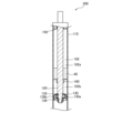
- FIG. 3 is a partial cross-sectional view of a shock absorber according to a second embodiment of the present invention.
- FIG. 4 is a partial cross-sectional view of a fluid pressure cylinder according to a comparative example of the present invention, showing the fluid pressure cylinder in its fully contracted state.
- FIG. 5 is a partial cross-sectional view of a fluid pressure cylinder according to a comparative example of the present invention, showing the fluid pressure cylinder in a fully extended state.
- the fluid pressure device according to the first embodiment is a hydraulic cylinder 100 that is driven using hydraulic oil as a working fluid.
- Fig. 1 shows the hydraulic cylinder 100 in a fully contracted state
- Fig. 2 shows the hydraulic cylinder 100 in a fully extended state.
- the fluid pressure device may be a fluid pressure cylinder that is driven using hydraulic water or the like as a working fluid other than hydraulic oil.
- the hydraulic cylinder 100 comprises a cylinder tube 10, a piston rod 20 inserted into the cylinder tube 10 so as to be freely movable back and forth, and a piston 30 connected to the piston rod 20 and dividing the interior of the cylinder tube 10 into a rod side chamber 2 and a bottom side chamber 3 (see Figure 2).
- the hydraulic cylinder 100 of this embodiment is used as a lift cylinder for lifting loads in lifting devices such as forklifts.
- the hydraulic cylinder 100 is a single-acting hydraulic cylinder, and is used with the axial direction of the cylinder tube 10 approximately aligned with the vertical direction, and the piston rod 20 is positioned above the piston 30.
- the cylinder tube 10 has a cylindrical main body 11, a cylinder head 12 as a head member that closes the opening at one end of the main body 11 and through which the piston rod 20 is inserted, and a cylinder bottom 13 as a bottom member that closes the opening at the other end of the main body 11.
- the cylinder head 12 is fastened to the main body 11 via fastening members (not shown) such as multiple bolts.
- the cylinder bottom 13 is joined to the main body 11 by, for example, welding.
- the piston 30 slides along the inner circumferential surface of the main body 11.
- the main body 11, the cylinder head 12, and the piston 30 define a rod side chamber 2, and the main body 11, the cylinder bottom 13, and the piston 30 define a bottom side chamber 3.
- the rod side chamber 2 contains multiple particles 40 and gas. Details of the multiple particles 40 will be described later.
- the cylinder head 12 is formed in an annular shape.
- a bearing 5 that slidably supports the piston rod 20 is provided on the inner circumference of the cylinder head 12.
- a dust seal 6 and a main seal 7 that slides against the outer circumferential surface of the piston rod 20 are also provided on the inner circumference of the cylinder head 12.
- the dust seal 6 prevents dust from entering the cylinder tube 10.
- the main seal 7 seals the rod side chamber 2 inside the cylinder tube 10.
- the cylinder bottom 13 is formed with a supply/discharge port 13a that communicates with the bottom side chamber 3.
- the supply/discharge port 13a is selectively connected to a hydraulic source such as a pump (not shown) and a tank (not shown), for example, via a switching valve (not shown).
- a hydraulic source such as a pump (not shown) and a tank (not shown)
- the piston 30 and piston rod 20 are driven upward as shown in FIG. 2, and the hydraulic cylinder 100 extends.
- the pressure in the bottom side chamber 3 decreases, the piston 30 and piston rod 20 move downward by their own weight, the hydraulic oil in the bottom side chamber 3 is discharged to the tank, and the hydraulic cylinder 100 contracts.
- the piston 30 has a housing hole 31 that houses the lower end 20a of the piston rod 20.
- the piston 30 is fitted to the piston rod 20 with the lower end surface 20b of the piston rod 20 abutting the bottom 31a of the housing hole 31.
- the annular groove 32 provided on the inner surface of the housing hole 31 of the piston 30 and the annular groove 21 provided on the outer surface of the lower end 20a of the piston rod 20 face each other.
- a snap ring 8 is fitted into the space formed by the annular grooves 21 and 32. As a result, the piston rod 20 and the piston 30 are engaged and connected to each other in the axial direction. As shown in FIG.
- the piston 30 abuts against the cylinder bottom 13, thereby restricting the compression stroke of the hydraulic cylinder 100.
- small gaps are formed between the outer peripheral surface of the lower end 20a of the piston rod 20 and the inner peripheral surface of the accommodation hole 31 of the piston 30, and between the lower end surface 20b of the piston rod 20 and the bottom 31a of the accommodation hole 31.
- a bearing 35 and a seal ring 36 are provided on the outer peripheral surface of the piston 30.
- the piston 30 is in sliding contact with the inner peripheral surface of the body portion 11 of the cylinder tube 10 via the bearing 35.
- the seal ring 36 seals the gap between the outer peripheral surface of the piston 30 and the inner peripheral surface of the body portion 11 of the cylinder tube 10, preventing hydraulic oil in the bottom side chamber 3 from leaking into the rod side chamber 2.
- the piston 30 also has a through hole 33 formed by axially penetrating the bottom 31a of the accommodation hole 31.
- the through hole 33 is formed coaxially with the piston rod 20.
- a check valve 38 is provided in the through hole 33.
- the check valve 38 only allows the flow of fluid from above to below the piston 30.
- the check valve 38 can have a known configuration, so a detailed description will be omitted.
- the multiple particles 40 are used to decelerate the piston rod 20 near the stroke end on the extension side, and are made of an elastic body.
- the particles 40 are made of rubber such as nitrile rubber (NBR) or silicone resin.
- the particles 40 are housed in the rod side chamber 2, and are formed to a size that does not allow them to leak out of the rod side chamber 2 between the inner circumferential surface of the main body 11 of the cylinder tube 10 and the outer circumferential surface of the piston 30, and between the outer circumferential surface of the lower end 20a of the piston rod 20 and the inner circumferential surface of the housing hole 31 of the piston 30.
- the particles 40 have a diameter of 1 mm to 10 mm.
- the diameter of the particles 40 is not limited to this.
- the particles 40 are made of an elastic body, they are elastically deformed when subjected to an external force. Therefore, when hydraulic oil is supplied to the bottom side chamber 3 from the fully contracted state of the hydraulic cylinder 100 shown in FIG. 1, the piston rod 20 moves upward to extend the hydraulic cylinder 100, and as shown in FIG. 2, the multiple particles 40 are compressed between the piston 30 and the cylinder head 12 near the stroke end. At this time, the elastic force from the multiple particles 40, the frictional force generated between the multiple particles 40, the frictional force generated between the multiple particles 40 and the main body 11 of the cylinder tube 10, and the frictional force generated between the multiple particles 40 and the outer circumferential surface of the piston rod 20 act downward as damping forces on the piston rod 20.
- the multiple particles 40 are further compressed and the elastic force increases, so that the damping force acting on the piston rod 20 increases.
- a cushioning effect is exerted in which the piston rod 20 is decelerated near the stroke end on the extension side, and the impact when the piston rod 20 reaches the stroke end on the extension side is mitigated.
- the "member fixed to the piston rod” described in the claims refers to the piston 30.
- a hydraulic cylinder 300 according to a comparative example of the present invention will be described with reference to Figures 4 and 5. Note that components corresponding to those of the hydraulic cylinder 100 are given the same reference numerals and will not be described.
- the hydraulic cylinder 300 uses cushion oil 240, not multiple particles 40, to provide a cushioning effect that decelerates the piston rod 220 near the stroke end.
- a refill hole 211a for supplying cushion oil 240 to the rod side chamber 2 is formed by penetrating radially through the main body 211 of the cylinder tube 210.
- the refill hole 211a is sealed by a plug 215.
- the piston rod 220 is formed with a hollow portion 225 that opens to the lower end face 20b, a communication hole 226 that connects the hollow portion 225 to the rod side chamber 2, and an orifice 227.
- the orifice 227 is formed at a position closer to the lower end face 20b than the communication hole 226, and connects the hollow portion 225 to the rod side chamber 2 through a notch 230a formed in the piston 230.
- the cushion oil 240 is contained in the rod side chamber 2 and the hollow portion 225.
- a valve housing 250 extending in the axial direction is provided in the through hole 33 of the piston 230.
- the valve housing 250 has a through hole 251 formed in the axial direction and is provided to extend to the hollow portion 225 of the piston rod 220.
- a check valve 38 and a rod inner tube 260 are provided in the through hole 251.
- the rod inner tube 260 is provided to protrude upward from the valve housing 250. Therefore, when the liquid level of the cushion oil 240 exceeds the upper end of the rod inner tube 260, it is guided into the rod inner tube 260 and discharged into the bottom side chamber 3 through the check valve 38.
- the rod inner tube 260 is provided to regulate the amount of cushion oil 240 that is not guided into the rod inner tube 260 and is stored in the rod side chamber 2 and the hollow portion 225.
- the rod side chamber 2 and the bottom side chamber 3 communicate with each other through the communication hole 226 or the orifice 227, the hollow portion 225, the rod inner tube 260, the through hole 251, and the check valve 38.
- the rod side chamber 2 contracts and becomes highly pressurized, so that up to near the end of the stroke, the cushion oil 240 in the rod side chamber 2 is led mainly through the communication hole 226 to the hollow portion 225 of the piston rod 220. Because the communication hole 226 has a large flow passage cross-sectional area, the cushion oil 240 led from the rod side chamber 2 to the hollow portion 225 through the communication hole 226 does not encounter much resistance.
- the hydraulic cylinder 300 has a complex structure, since the cylinder tube 210 is provided with a refill hole 211a and a plug 215 to provide a cushioning effect, the piston rod 220 is provided with a hollow portion 225, a communication hole 226, and an orifice 227, and the piston 230 is provided with a valve housing 250 and a rod inner tube 260. Furthermore, the hydraulic cylinder 300 has a complex structure, which not only requires time and effort to process, but also requires a large number of parts, resulting in high manufacturing costs.
- the piston rod 20 is decelerated near the extension stroke end by compressing the multiple particles 40 contained in the rod side chamber 2.
- a cushioning effect can be exerted that decelerates the piston rod 20 near the extension stroke end. Therefore, there is no need to form a hollow portion, orifice, etc. in the piston rod 20. Therefore, a cushioning effect can be exerted with a simple structure.
- the cushioning effect is exerted by the multiple particles 40, so the degree of cushioning effect can be easily adjusted by adjusting the amount and material of the particles 40 contained in the rod side chamber 2. Even if the cushioning properties deteriorate, they can be easily improved by adding or replacing the particles 40, making maintenance easier.
- the above first embodiment provides the following effects.
- the fluid pressure device according to the second embodiment is a shock absorber 200 mounted on a vehicle or the like.
- the shock absorber 200 is interposed, for example, between the body and the axle of the vehicle, and generates a damping force to suppress vibration of the vehicle body.
- the shock absorber 200 includes a cylinder tube 110, a piston rod 120 inserted into the cylinder tube 110 so as to be movable back and forth, and a piston 130 connected to the piston rod 120 and dividing the interior of the cylinder tube 110 into a rod side chamber 102 and a bottom side chamber 103.
- An annular cylinder head 150 is provided at the end of the cylinder tube 110 on the rod side chamber 102 side.
- the cylinder head 150 slidably supports the piston rod 120 and seals the end of the cylinder tube 110 on the rod side chamber 102 side.
- the rod side chamber 102 and the bottom side chamber 103 contain hydraulic oil as a working fluid.
- the piston 130 has passages 130a, 130b that connect the rod side chamber 102 and the bottom side chamber 103.
- a damping valve 135 having multiple annular leaf valves is provided on the rod side chamber 102 side of the piston 130.
- a damping valve 136 having multiple annular leaf valves is provided on the bottom side chamber 103 side of the piston 130.
- the damping valve 135 opens due to the pressure difference between the rod side chamber 102 and the bottom side chamber 103 when the shock absorber 200 contracts, opening passage 130a and providing resistance to the flow of hydraulic oil moving from the bottom side chamber 103 to the rod side chamber 102 through passage 130a.
- the damping valve 135 closes passage 130a when the shock absorber 200 extends.
- the damping valve 136 opens due to the pressure difference between the rod side chamber 102 and the bottom side chamber 103 when the shock absorber 200 contracts, opening passage 130b and providing resistance to the flow of hydraulic oil moving from the rod side chamber 102 to the bottom side chamber 103 through passage 130b.
- the damping valve 136 closes passage 130b when the shock absorber 200 contracts.
- the damping valve 135 applies a damping force to the piston 130 when the shock absorber 200 contracts, and the damping valve 136 applies a damping force to the piston 130 when the shock absorber 200 expands.
- a support 160 is provided on the outer peripheral surface of the piston rod 120.
- the support 160 is, for example, a pressed metal part and is fixed to the outer peripheral surface of the piston rod 120 by welding or the like.
- the support 160 is provided above the piston 130 and regulates the extension stroke of the shock absorber 200.
- the support 160 extends radially to the vicinity of the inner peripheral surface of the cylinder tube 110.
- the rod side chamber 102 is divided by the support 160 into a first chamber 102a above the support 160 and a second chamber 102b below the support 160.
- a plurality of particles 40 are stored in the first chamber 102a by being accumulated on the support 160.
- the gap between the support 160 and the inner peripheral surface of the cylinder tube 110 is set to be smaller than the diameter of the particles 40.
- the particles 40 are formed of an elastic body and are intended to decelerate the piston rod 120 near the stroke end on the extension side.
- the multiple particles 40 are compressed between the support 160 and the cylinder head 150 near the stroke end.
- the elastic force from the multiple particles 40, the frictional force generated between the multiple particles 40, and the frictional force generated between the multiple particles 40 and the cylinder tube 110 act downward as damping forces on the piston rod 120.
- the multiple particles 40 are further compressed and the elastic force becomes larger, so that the damping force acting on the piston rod 120 becomes larger.
- the "member fixed to the piston rod” described in the claims refers to the support 160.
- shock absorber 200 of this embodiment similar to the hydraulic cylinder 100 of the first embodiment, it is possible to exert a cushioning effect that decelerates the piston rod 120 near the extension stroke end simply by accommodating a plurality of particles 40 in the rod side chamber 102. Therefore, there is no need to form a hollow portion or an orifice in the piston rod 120, and the cushioning effect can be exerted with a simple structure.
- the shock absorber 200 of this embodiment as in the hydraulic cylinder 100 of the first embodiment, there is no need to form a hollow portion in the piston rod 120, so the strength of the piston rod 120 is increased and the diameter of the piston rod 120 can be reduced compared to when a hollow portion is formed. Also, by adjusting the amount of particles 40 contained in the rod side chamber 102, the degree of cushioning effect can be easily adjusted, and even if the cushioning properties deteriorate, they can be easily improved by adding or replacing particles 40.
- the second embodiment described above provides the following effects.
- shock absorber 200 simply by storing multiple particles 40 in the rod side chamber 102, it is possible to exert a cushioning effect that decelerates the piston rod 120 near the end of the stroke on the extension side. Therefore, there is no need to form a hollow section or orifice in the piston rod 120, and the cushioning effect can be exerted with a simple structure.
- a plurality of particles 40 for decelerating the piston rod 20 near the stroke end on the extension side are accommodated in the rod side chamber 2.
- a plurality of particles 40 may be accommodated in the bottom side chamber 3 for decelerating the piston rod 20 near the stroke end on the contraction side.
- a filter is provided to cover the opening of the supply/discharge port 13a in the cylinder bottom 13 so that the plurality of particles 40 accommodated in the bottom side chamber 3 are not discharged from the supply/discharge port 13a.
- the filter allows the hydraulic oil supplied to and discharged from the bottom side chamber 3 to pass through, and blocks the plurality of particles 40 from being discharged from the supply/discharge port 13a. Even with this configuration, the same effect as in the above embodiment is achieved.
- the plurality of particles 40 may be accommodated in both the rod side chamber 2 and the bottom side chamber 3. In other words, in the hydraulic cylinder 100, it is sufficient that at least one of the rod side chamber 2 and the bottom side chamber 3 accommodates a plurality of particles 40 for decelerating the piston rod 20 near the stroke end.
- the fluid pressure device (hydraulic cylinder 100, shock absorber 200) comprises a cylinder tube 10, 110, a piston rod 20, 120 inserted into the cylinder tube 10, 110 so as to be freely movable back and forth, and a piston 30, 130 connected to the piston rod 20, 120 and dividing the inside of the cylinder tube 10, 110 into a rod side chamber 2, 102 and a bottom side chamber 3, 103.
- At least one of the rod side chamber 2, 102 and the bottom side chamber 3, 103 contains a plurality of particles 40 for decelerating the piston rod 20, 120 near the stroke end.
- the plurality of particles 40 are made of an elastic body, and are compressed by a member (piston 30, support 160) fixed to the piston rod 20, 120 to decelerate the piston rod 20, 120.
- the piston rod 20, 120 is decelerated near the stroke end by compressing the multiple particles 40 contained in at least one of the rod side chamber 2, 102 and the bottom side chamber 3, 103.
- a cushioning effect that decelerates the piston rod 20, 120 near the stroke end can be exerted. Therefore, there is no need to form a hollow portion, an orifice, etc. in the piston rod 20, 120. Therefore, a cushioning effect can be exerted with a simple structure.
- This configuration allows the fluid pressure device (hydraulic cylinder 100, shock absorber 200) that decelerates the piston 30, 130 near the stroke end when extending to provide a cushioning effect with a simple structure.
- the fluid pressure device is a single-acting fluid pressure cylinder (hydraulic cylinder 100).
- a single-acting fluid pressure cylinder (hydraulic cylinder 100) can achieve a cushioning effect with a simple structure.
- the multiple particles 40 have a diameter of 1 mm-10 mm.
Landscapes
- Engineering & Computer Science (AREA)
- General Engineering & Computer Science (AREA)
- Mechanical Engineering (AREA)
- Physics & Mathematics (AREA)
- Fluid Mechanics (AREA)
- Actuator (AREA)
- Fluid-Damping Devices (AREA)
Abstract
油圧シリンダ(100)は、シリンダチューブ(10)と、シリンダチューブ(10)に進退自在に挿入されるピストンロッド(20)と、ピストンロッド(20)に連結されシリンダチューブ(10)内をロッド側室(2)とボトム側室(3)とに区画するピストン(30)と、を備え、ロッド側室(2)及びボトム側室(3)の少なくとも一方には、ピストンロッド(20)をストローク端付近で減速させるための複数の粒子(40)が収容され、複数の粒子(40)は、弾性体で形成され、ピストンロッド(20)に固定された部材(ピストン(30))により圧縮されることでピストンロッド(20)を減速させる。
Description
本発明は、流体圧機器に関する。
JP2014-43875Aには、ピストンが摺動自在に収容され内部にボトム側室及びロッド側室を有する筒状のシリンダチューブと、ピストンに連結されシリンダチューブの開口端から摺動自在に突出する筒状のピストンロッドと、ピストンロッドの内部に画成されるロッド内室と、ロッド内室を封止するロッドヘッドと、を備えることを特徴とする液圧シリンダが開示されている。液圧シリンダは、ボトム側室に作動液が給排されることにより伸縮する。ピストンロッドには、ロッド側室とロッド内室を連通するようにポートとオリフィスがそれぞれ形成され、ロッド側室にはクッション用油が入れられる。
JP2014-43875Aに記載の液圧シリンダが伸長すると、ロッド側室が収縮し圧力が高まることにより、ロッド側室のクッション用油がポート及びオリフィスを通じてロッド内室に流入する。ピストンロッドがストローク端に近づくと、ポートが閉塞されてクッション用油がオリフィスのみを通じてロッド内室に流入する。オリフィスがクッション用油の流れに抵抗を付与することで、ピストンロッドが減速し、ピストンロッドがストローク端に達する際の衝撃が緩和される。
JP2014-43875Aに記載のような流体圧シリンダでは、ピストンがストローク端に達する際の衝撃を緩和するために、ピストンロッドにロッド内室、ポート、及びオリフィスが形成され、ロッド内室がロッドヘッドにより封止される。そのため、流体圧シリンダの構造が複雑である。
本発明は、流体圧機器において、簡易な構造でクッション作用を発揮させることを目的とする。
本発明のある態様によれば、流体圧機器であって、シリンダチューブと、前記シリンダチューブに進退自在に挿入されるピストンロッドと、前記ピストンロッドに連結され前記シリンダチューブ内をロッド側室とボトム側室とに区画するピストンと、を備え、前記ロッド側室及び前記ボトム側室の少なくとも一方には、前記ピストンロッドをストローク端付近で減速させるための複数の粒子が収容され、前記複数の粒子は、弾性体で形成され、前記ピストンロッドに固定された部材により圧縮されることで前記ピストンロッドを減速させる。
図面を参照して、本発明の実施形態に係る流体圧機器について説明する。
<第1実施形態>
図1、図2を参照して、第1実施形態に係る流体圧機器について説明する。第1実施形態に係る流体圧機器は、作動油を作動流体として駆動する油圧シリンダ100である。図1は油圧シリンダ100が最収縮した状態を示しており、図2は油圧シリンダ100が最伸長した状態を示している。なお、流体圧機器は、作動油以外の作動水等を作動流体として駆動する流体圧シリンダであってもよい。
図1、図2を参照して、第1実施形態に係る流体圧機器について説明する。第1実施形態に係る流体圧機器は、作動油を作動流体として駆動する油圧シリンダ100である。図1は油圧シリンダ100が最収縮した状態を示しており、図2は油圧シリンダ100が最伸長した状態を示している。なお、流体圧機器は、作動油以外の作動水等を作動流体として駆動する流体圧シリンダであってもよい。
油圧シリンダ100は、シリンダチューブ10と、シリンダチューブ10に進退自在に挿入されるピストンロッド20と、ピストンロッド20に連結されシリンダチューブ10内をロッド側室2とボトム側室3(図2参照)とに区画するピストン30と、を備える。
本実施形態の油圧シリンダ100は、フォークリフトなどの昇降装置において積荷を昇降させるリフトシリンダとして用いられる。油圧シリンダ100は単動型の油圧シリンダであり、シリンダチューブ10の軸方向が鉛直方向と略一致する向きで使用され、ピストンロッド20がピストン30の上部に配置される。
シリンダチューブ10は、筒状の本体部11と、本体部11の一端の開口部を閉塞しピストンロッド20が挿通されるヘッド部材としてのシリンダヘッド12と、本体部11の他端の開口部を閉塞するボトム部材としてのシリンダボトム13と、を有する。シリンダヘッド12は、例えば複数のボルト等の締結部材(図示せず)を介して本体部11に締結される。シリンダボトム13は、本体部11に例えば溶接により接合される。ピストン30は、本体部11の内周面に沿って摺動する。本体部11、シリンダヘッド12、及びピストン30によって、ロッド側室2が区画され、本体部11、シリンダボトム13、及びピストン30によって、ボトム側室3が区画される。ロッド側室2には、複数の粒子40と気体が収容される。複数の粒子40の詳細については後述する。
シリンダヘッド12は環状に形成される。シリンダヘッド12の内周には、ピストンロッド20を摺動自在に支持するベアリング5が設けられる。また、シリンダヘッド12の内周にはさらに、ダストシール6と、ピストンロッド20の外周面に摺接するメインシール7が設けられる。ダストシール6は、シリンダチューブ10内へのダストの侵入を防止する。メインシール7は、シリンダチューブ10内のロッド側室2を密封する。
シリンダボトム13には、ボトム側室3と連通する給排ポート13aが形成される。給排ポート13aは、例えば切換弁(図示省略)を介して、ポンプ等の油圧源(図示省略)及びタンク(図示省略)と選択的に接続される。ボトム側室3に油圧源から作動油が供給されボトム側室3内の圧力が上昇すると、図2に示すようにピストン30及びピストンロッド20が上方へ駆動され、油圧シリンダ100が伸長する。一方で、ボトム側室3内の圧力が低下すると、ピストン30及びピストンロッド20が自重によって下方へと移動し、ボトム側室3の作動油がタンクに排出されて油圧シリンダ100が収縮する。
ピストン30は、ピストンロッド20の下端部20aを収容する収容穴31を有する。ピストン30は、ピストンロッド20の下端面20bが収容穴31の底部31aに当接して、ピストンロッド20に嵌合される。ピストン30がピストンロッド20に嵌合された状態では、ピストン30の収容穴31の内周面に設けられる環状溝32とピストンロッド20の下端部20aの外周面に設けられる環状溝21が対向する。環状溝21,32により形成される空間には、スナップリング8が嵌装される。これにより、ピストンロッド20とピストン30が互いに軸方向に係止され、連結される。図1に示すように、ピストン30がシリンダボトム13に当接することで、油圧シリンダ100の縮み側のストロークが規制される。なお、ピストンロッド20の下端部20aの外周面とピストン30の収容穴31の内周面との間、及びピストンロッド20の下端面20bと収容穴31の底部31aとの間には、わずかな隙間が形成される。後述するように、油圧シリンダ100が伸長する際には、この隙間とチェックバルブ38を通じて、ロッド側室2の気体と作動油がボトム側室3に排出される。
ピストン30の外周面には、ベアリング35とシールリング36が設けられる。ピストン30は、ベアリング35を介してシリンダチューブ10の本体部11の内周面に摺接する。シールリング36は、ピストン30の外周面とシリンダチューブ10の本体部11の内周面との間を封止し、ボトム側室3の作動油がロッド側室2に漏出することを抑制する。
また、ピストン30は、収容穴31の底部31aを軸方向に貫通して形成される貫通孔33を有する。貫通孔33は、ピストンロッド20と同軸上に形成される。貫通孔33には、チェックバルブ38が設けられる。チェックバルブ38は、ピストン30の上方から下方へ流れる流体の流れのみを許容する。チェックバルブ38は、公知の構成を採用できるため、詳細な説明を省略する。
ピストン30の外周面にはシールリング36が設けられるものの、油圧源からボトム側室3に作動油が供給され、ピストンロッド20が上方に駆動されて油圧シリンダ100が伸長する際には、ボトム側室3の作動油の一部がシールリング36を超えてロッド側室2に漏出してしまう可能性がある。しかしながら、油圧シリンダ100の伸長時には、ロッド側室2が収縮し、ロッド側室2の気体とロッド側室2に漏出した作動油が、ピストンロッド20の下端部20aの外周面とピストン30の収容穴31の内周面との間、ピストンロッド20の下端面20bと収容穴31の底部31aとの間、及び貫通孔33を通じてチェックバルブ38に導かれ、ボトム側室3に排出される。これにより、油圧シリンダ100がストローク端付近までスムーズに伸長する。
次に、複数の粒子40の詳細について説明する。
複数の粒子40は、ピストンロッド20を伸び側のストローク端付近で減速させるためのものであり、弾性体で形成される。具体的には、粒子40は、ニトリルゴム(NBR)等のゴムやシリコン樹脂で形成される。粒子40は、ロッド側室2に収容され、シリンダチューブ10の本体部11の内周面とピストン30の外周面との間、及びピストンロッド20の下端部20aの外周面とピストン30の収容穴31の内周面との間を通じて、ロッド側室2から漏出しない大きさに形成される。具体的には、粒子40は、直径が1mm-10mmである。なお、粒子40の直径はこれに限らない。
粒子40は、弾性体で形成されるため、外力を受けると弾性変形する。よって、図1に示す油圧シリンダ100が最収縮した状態から、ボトム側室3に作動油が供給されピストンロッド20が上方に移動して油圧シリンダ100が伸長すると、図2に示すように、ストローク端付近では複数の粒子40はピストン30によりシリンダヘッド12との間で圧縮される。この際、ピストンロッド20には、複数の粒子40からの弾性力、複数の粒子40同士の間で生じる摩擦力、複数の粒子40とシリンダチューブ10の本体部11との間で生じる摩擦力、及び複数の粒子40とピストンロッド20の外周面との間で生じる摩擦力が、減衰力として下方に向けて作用する。ピストンロッド20がストローク端に近づくにつれて、複数の粒子40がより圧縮されて弾性力が大きくなるため、ピストンロッド20に作用する減衰力が大きくなる。これにより、ピストンロッド20が伸び側のストローク端付近で減速されるクッション作用が発揮され、ピストンロッド20が伸び側のストローク端に達する際の衝撃が緩和される。なお、本実施形態では、特許請求の範囲に記載の「ピストンロッドに固定された部材」とは、ピストン30のことである。
ここで、図4、図5を参照して、本発明の比較例に係る油圧シリンダ300について説明する。なお、油圧シリンダ100と対応する構成には同一の符号を付して説明を省略する。
油圧シリンダ300は、複数の粒子40ではなくクッション油240により、ピストンロッド220がストローク端付近で減速されるクッション作用が発揮される。
具体的には、シリンダチューブ210の本体部211には、ロッド側室2にクッション油240を入れるための補充孔211aが径方向に貫通して形成される。補充孔211aは、プラグ215により封止される。ピストンロッド220には、下端面20bに開口する中空部225と、中空部225とロッド側室2を連通する連通孔226及びオリフィス227と、が形成される。オリフィス227は、連通孔226よりも下端面20bに近い位置に形成され、ピストン230に形成される切り欠き230aを通じて中空部225とロッド側室2を連通する。図4に示すように、油圧シリンダ300が最収縮した状態では、クッション油240はロッド側室2及び中空部225に収容される。
ピストン230の貫通孔33には、軸方向に延びて形成されるバルブハウジング250が設けられる。バルブハウジング250は、軸方向に貫通して形成される貫通孔251を有し、ピストンロッド220の中空部225まで延びて設けられる。貫通孔251には、チェックバルブ38とロッド内管260が設けられる。ロッド内管260は、バルブハウジング250から上方に突出して設けられる。よって、クッション油240は、液面がロッド内管260の上端を超えると、ロッド内管260内に導かれチェックバルブ38を通じてボトム側室3に排出される。言い換えれば、ロッド内管260は、ロッド内管260内に導かれずにロッド側室2及び中空部225に貯留されるクッション油240の量を規定するために設けられる。ロッド側室2とボトム側室3は、連通孔226またはオリフィス227、中空部225、ロッド内管260、貫通孔251、及びチェックバルブ38を通じて連通する。
図4に示す油圧シリンダ300が最収縮した状態から油圧シリンダ300が伸長すると、ロッド側室2が収縮し高圧になるため、ストローク端付近までは、ロッド側室2のクッション油240が主に連通孔226を通じてピストンロッド220の中空部225に導かれる。連通孔226は流路断面積が大きいため、ロッド側室2から連通孔226を通じて中空部225に導かれるクッション油240には、大きな抵抗は生じない。
図5に示すように、油圧シリンダ300がストローク端付近まで伸長すると、連通孔226を通じたロッド側室2とボトム側室3の連通が遮断される。そのため、ロッド側室2のクッション油240は、オリフィス227のみを通じてピストンロッド220の中空部225に導かれる。オリフィス227は流路断面積が小さいため、ロッド側室2からオリフィス227を通じて中空部225に導かれるクッション油240には、大きな抵抗が生じる。これにより、ピストンロッド220が伸び側のストローク端付近で減速されるクッション作用が発揮される。
このように、本発明の比較例に係る油圧シリンダ300では、クッション作用を発揮させるために、シリンダチューブ210に補充孔211a及びプラグ215が設けられ、ピストンロッド220に中空部225、連通孔226、及びオリフィス227が設けられ、ピストン230にバルブハウジング250及びロッド内管260が設けられるため、構造が複雑である。また、油圧シリンダ300は、構造が複雑であるため加工に手間がかかるだけでなく、部品点数も多いため、製造コストが高い。
これに対し、本実施形態の油圧シリンダ100では、ピストンロッド20は、ロッド側室2に収容される複数の粒子40が圧縮されることにより、伸び側のストローク端付近で減速される。言い換えれば、複数の粒子40をロッド側室2に収容することのみで、ピストンロッド20を伸び側のストローク端付近で減速させるクッション作用を発揮させることができる。そのため、ピストンロッド20に中空部やオリフィス等を形成する必要がない。よって、簡易な構造でクッション作用を発揮させることができる。
また、油圧シリンダ100では、ピストンロッド20に中空部を形成する必要がないため、中空部を形成する場合と比較してピストンロッド20の強度が高くなる。よって、ピストンロッド20を小径化することができる。
また、油圧シリンダ100では、複数の粒子40によりクッション作用を発揮させるため、ロッド側室2に収容される粒子40の量や材質等を調整することにより、クッション作用の程度を容易に調整することができる。また、クッション性が悪化しても、粒子40の追加や交換をすることによりクッション性を容易に向上させることができ、メンテナンスが容易になる。
以上の第1実施形態によれば、以下に示す作用効果を奏する。
油圧シリンダ100では、複数の粒子40をロッド側室2に収容することのみで、ピストンロッド20を伸び側のストローク端付近で減速させるクッション作用を発揮させることができる。そのため、ピストンロッド20に中空部やオリフィス等を形成する必要がなく、簡易な構造でクッション作用を発揮させることができる。
<第2実施形態>
図3を参照して、第2実施形態に係る流体圧機器について説明する。第2実施形態に係る流体圧機器は、車両等に搭載されるショックアブソーバ200である。ショックアブソーバ200は、例えば、車両の車体と車軸との間に介装され、減衰力を発生させて車体の振動を抑制する。
図3を参照して、第2実施形態に係る流体圧機器について説明する。第2実施形態に係る流体圧機器は、車両等に搭載されるショックアブソーバ200である。ショックアブソーバ200は、例えば、車両の車体と車軸との間に介装され、減衰力を発生させて車体の振動を抑制する。
ショックアブソーバ200は、シリンダチューブ110と、シリンダチューブ110に進退自在に挿入されるピストンロッド120と、ピストンロッド120に連結されシリンダチューブ110内をロッド側室102とボトム側室103とに区画するピストン130と、を備える。
シリンダチューブ110のロッド側室102側の端部には、環状のシリンダヘッド150が設けられる。シリンダヘッド150は、ピストンロッド120を摺動自在に支持するとともに、シリンダチューブ110のロッド側室102側の端部を封止する。ロッド側室102とボトム側室103には、作動流体として作動油が収容される。
ピストン130は、ロッド側室102とボトム側室103とを連通する通路130a、130bを有する。ピストン130のロッド側室102側には、複数の環状のリーフバルブを有する減衰バルブ135が設けられる。また、ピストン130のボトム側室103側には、複数の環状のリーフバルブを有する減衰バルブ136が設けられる。
減衰バルブ135は、ショックアブソーバ200の収縮時にロッド側室102とボトム側室103の差圧により開弁して通路130aを開放するとともに、通路130aを通ってボトム側室103からロッド側室102に移動する作動油の流れに抵抗を与える。減衰バルブ135は、ショックアブソーバ200の伸長時には、通路130aを閉塞する。減衰バルブ136は、ショックアブソーバ200の伸長時に開弁して通路130bを開放するとともに、通路130bを通ってロッド側室102からボトム側室103に移動する作動油の流れに抵抗を与える。減衰バルブ136は、ショックアブソーバ200の収縮時には、通路130bを閉塞する。つまり、減衰バルブ135はショックアブソーバ200の収縮時にピストン130に減衰力を作用させ、減衰バルブ136はショックアブソーバ200の伸長時にピストン130に減衰力を作用させる。
ピストンロッド120の外周面には、サポート160が設けられる。サポート160は、例えば、金属製のプレス成形品であり溶接等によりピストンロッド120の外周面に固定される。サポート160は、ピストン130よりも上方に設けられ、ショックアブソーバ200の伸び側のストロークを規制する。サポート160は、シリンダチューブ110の内周面近傍まで径方向に延びて設けられる。よって、ロッド側室102は、サポート160により、サポート160の上方の第1室102aとサポート160の下方の第2室102bに区画される。第1室102aには、複数の粒子40がサポート160に堆積されて収容される。サポート160とシリンダチューブ110の内周面との間の隙間は、粒子40の直径よりも小さく設定される。これにより、粒子40がサポート160の下方に落下して通路130a、130bを閉塞することが防止され、ショックアブソーバ200の動作に悪影響を与えることが防止される。ショックアブソーバ200では、このようにして、ロッド側室102(第1室102a)に複数の粒子40が収容される。
粒子40は、第1実施形態と同様に、弾性体で形成され、ピストンロッド120を伸び側のストローク端付近で減速させるためのものである。図3に示す状態からピストンロッド120が上方に移動してショックアブソーバ200が伸長すると、ストローク端付近では複数の粒子40がサポート160によりシリンダヘッド150との間で圧縮される。この際、ピストンロッド120には、減衰バルブ136による減衰力に加えて、複数の粒子40からの弾性力、複数の粒子40同士の間で生じる摩擦力、及び複数の粒子40とシリンダチューブ110との間で生じる摩擦力が、減衰力として下方に向けて作用する。ピストンロッド120がストローク端に近づくにつれて、複数の粒子40がより圧縮されて弾性力が大きくなるため、ピストンロッド120に作用する減衰力が大きくなる。これにより、ピストンロッド120が伸び側のストローク端付近で減速されるクッション作用が発揮され、ピストンロッド120が伸び側のストローク端に達する際の衝撃が緩和される。なお、本実施形態では、特許請求の範囲に記載の「ピストンロッドに固定された部材」とは、サポート160のことである。
このように、本実施形態のショックアブソーバ200では、第1実施形態の油圧シリンダ100と同様に、複数の粒子40をロッド側室102に収容することのみで、ピストンロッド120を伸び側のストローク端付近で減速させるクッション作用を発揮させることができる。そのため、ピストンロッド120に中空部やオリフィス等を形成する必要がなく、簡易な構造でクッション作用を発揮させることができる。
さらに、本実施形態のショックアブソーバ200では、第1実施形態の油圧シリンダ100と同様に、ピストンロッド120に中空部を形成する必要がないため、中空部を形成する場合と比較してピストンロッド120の強度が高くなり、ピストンロッド120を小径化することができる。また、ロッド側室102に収容される粒子40の量を調整することにより、クッション作用の程度を容易に調整することができ、クッション性が悪化しても、粒子40の追加や交換をすることによりクッション性を容易に向上させることができる。
以上の第2実施形態によれば、以下に示す作用効果を奏する。
ショックアブソーバ200では、複数の粒子40をロッド側室102に収容することのみで、ピストンロッド120を伸び側のストローク端付近で減速させるクッション作用を発揮させることができる。そのため、ピストンロッド120に中空部やオリフィス等を形成する必要がなく、簡易な構造でクッション作用を発揮させることができる。
次に、上記実施形態の変形例について説明する。以下のような変形例も本発明の範囲内であり、以下の変形例と上記実施形態の構成とを組み合わせることも可能である。
<変形例>
上記第1実施形態では、ピストンロッド20を伸び側のストローク端付近で減速させるための複数の粒子40が、ロッド側室2に収容される。これに代えて、ピストンロッド20を縮み側のストローク端付近で減速させるために、ボトム側室3に複数の粒子40が収容されてもよい。この構成では、ボトム側室3に収容される複数の粒子40が給排ポート13aから排出されないように、シリンダボトム13における給排ポート13aの開口を覆うフィルターが設けられる。フィルターは、ボトム側室3に給排される作動油を透過するとともに、複数の粒子40が給排ポート13aから排出されないように遮断する。この構成であっても、上記実施形態と同様の効果を奏する。
上記第1実施形態では、ピストンロッド20を伸び側のストローク端付近で減速させるための複数の粒子40が、ロッド側室2に収容される。これに代えて、ピストンロッド20を縮み側のストローク端付近で減速させるために、ボトム側室3に複数の粒子40が収容されてもよい。この構成では、ボトム側室3に収容される複数の粒子40が給排ポート13aから排出されないように、シリンダボトム13における給排ポート13aの開口を覆うフィルターが設けられる。フィルターは、ボトム側室3に給排される作動油を透過するとともに、複数の粒子40が給排ポート13aから排出されないように遮断する。この構成であっても、上記実施形態と同様の効果を奏する。
また、複数の粒子40は、ロッド側室2に収容されるとともに、ボトム側室3に収容されてもよい。つまり、油圧シリンダ100では、ロッド側室2及びボトム側室3の少なくとも一方にピストンロッド20をストローク端付近で減速させるための複数の粒子40が収容されればよい。
以上のように構成された本発明の実施形態の構成、作用、及び効果をまとめて説明する。
流体圧機器(油圧シリンダ100、ショックアブソーバ200)は、シリンダチューブ10,110と、シリンダチューブ10,110に進退自在に挿入されるピストンロッド20,120と、ピストンロッド20,120に連結されシリンダチューブ10,110内をロッド側室2,102とボトム側室3,103とに区画するピストン30,130と、を備え、ロッド側室2,102及びボトム側室3,103の少なくとも一方には、ピストンロッド20,120をストローク端付近で減速させるための複数の粒子40が収容され、複数の粒子40は、弾性体で形成され、ピストンロッド20,120に固定された部材(ピストン30,サポート160)により圧縮されることでピストンロッド20,120を減速させる。
この構成では、ピストンロッド20,120は、ロッド側室2,102及びボトム側室3,103の少なくとも一方に収容される複数の粒子40が圧縮されることにより、ストローク端付近で減速される。言い換えれば、複数の粒子40をロッド側室2,102及びボトム側室3,103の少なくとも一方に収容することのみで、ピストンロッド20,120をストローク端付近で減速させるクッション作用を発揮させることができる。そのため、ピストンロッド20,120に中空部やオリフィス等を形成する必要がない。よって、簡易な構造でクッション作用を発揮させることができる。
また、流体圧機器(油圧シリンダ100、ショックアブソーバ200)では、複数の粒子40は、ロッド側室2,102に収容され、流体圧機器(油圧シリンダ100、ショックアブソーバ200)が伸長する際にピストンロッド20,120をストローク端付近で減速させる。
この構成では、伸長する際にピストン30,130をストローク端付近で減速させる流体圧機器(油圧シリンダ100、ショックアブソーバ200)において、簡易な構造でクッション作用を発揮させることができる。
また、流体圧機器は、単動型の流体圧シリンダ(油圧シリンダ100)である。
この構成では、単動型の流体圧シリンダ(油圧シリンダ100)において、簡易な構造でクッション作用を発揮させることができる。
また、流体圧機器(油圧シリンダ100、ショックアブソーバ200)では、複数の粒子40は、直径が1mm-10mmである。
以上、本発明の実施形態について説明したが、上記実施形態は本発明の適用例の一部を示したに過ぎず、本発明の技術的範囲を上記実施形態の具体的構成に限定する趣旨ではない。
本願は2023年3月28日に日本国特許庁に出願された特願2023-50769に基づく優先権を主張し、この出願の全ての内容は参照により本明細書に組み込まれる。
Claims (4)
- 流体圧機器であって、
シリンダチューブと、
前記シリンダチューブに進退自在に挿入されるピストンロッドと、
前記ピストンロッドに連結され前記シリンダチューブ内をロッド側室とボトム側室とに区画するピストンと、を備え、
前記ロッド側室及び前記ボトム側室の少なくとも一方には、前記ピストンロッドをストローク端付近で減速させるための複数の粒子が収容され、
前記複数の粒子は、弾性体で形成され、前記ピストンロッドに固定された部材により圧縮されることで前記ピストンロッドを減速させる流体圧機器。 - 請求項1に記載の流体圧機器であって、
前記複数の粒子は、前記ロッド側室に収容され、前記流体圧機器が伸長する際に前記ピストンロッドをストローク端付近で減速させる流体圧機器。 - 請求項2に記載の流体圧機器であって、
前記流体圧機器は、単動型の流体圧シリンダである流体圧機器。 - 請求項1に記載の流体圧機器であって、
前記複数の粒子は、直径が1mm-10mmである流体圧機器。
Applications Claiming Priority (2)
| Application Number | Priority Date | Filing Date | Title |
|---|---|---|---|
| JP2023-050769 | 2023-03-28 | ||
| JP2023050769A JP2024139848A (ja) | 2023-03-28 | 2023-03-28 | 流体圧機器 |
Publications (1)
| Publication Number | Publication Date |
|---|---|
| WO2024203263A1 true WO2024203263A1 (ja) | 2024-10-03 |
Family
ID=92905734
Family Applications (1)
| Application Number | Title | Priority Date | Filing Date |
|---|---|---|---|
| PCT/JP2024/009471 Ceased WO2024203263A1 (ja) | 2023-03-28 | 2024-03-12 | 流体圧機器 |
Country Status (2)
| Country | Link |
|---|---|
| JP (1) | JP2024139848A (ja) |
| WO (1) | WO2024203263A1 (ja) |
Citations (1)
| Publication number | Priority date | Publication date | Assignee | Title |
|---|---|---|---|---|
| JP2017227237A (ja) * | 2016-06-21 | 2017-12-28 | Kyb株式会社 | ダンパ |
-
2023
- 2023-03-28 JP JP2023050769A patent/JP2024139848A/ja active Pending
-
2024
- 2024-03-12 WO PCT/JP2024/009471 patent/WO2024203263A1/ja not_active Ceased
Patent Citations (1)
| Publication number | Priority date | Publication date | Assignee | Title |
|---|---|---|---|---|
| JP2017227237A (ja) * | 2016-06-21 | 2017-12-28 | Kyb株式会社 | ダンパ |
Also Published As
| Publication number | Publication date |
|---|---|
| JP2024139848A (ja) | 2024-10-10 |
Similar Documents
| Publication | Publication Date | Title |
|---|---|---|
| KR100621267B1 (ko) | 피스톤-실린더-유닛 | |
| US20210123495A1 (en) | Pressure relief for a hydraulic compression stop device | |
| TWI512213B (zh) | 雙向緩衝裝置 | |
| US20110180361A1 (en) | Stiff damper | |
| US20110227301A1 (en) | Vehicle Height Adjusting Apparatus | |
| JPH0254454B2 (ja) | ||
| WO2019221098A1 (ja) | シリンダ装置 | |
| JP5876855B2 (ja) | 流体圧シリンダ | |
| WO2024203263A1 (ja) | 流体圧機器 | |
| CN111594588A (zh) | 具有闭孔泡沫的密封张紧器 | |
| EP1396360B1 (en) | Self leveling vehicle suspension damper | |
| US20080100002A1 (en) | Cylinder apparatus | |
| JP2011214633A (ja) | シリンダ装置 | |
| KR102614825B1 (ko) | 쇽업소버 | |
| JP2023007996A (ja) | 車高調整機能付き緩衝器 | |
| JP5212812B2 (ja) | 液圧緩衝器 | |
| WO2022044833A1 (ja) | 多段式流体圧シリンダ | |
| JP5483559B2 (ja) | 磁気粘性流体流動型ダンパ | |
| KR102845963B1 (ko) | 쇽업소버 | |
| WO2022201671A1 (ja) | 緩衝器 | |
| JPH11325149A (ja) | ショックアブソ―バ | |
| WO2022130968A1 (ja) | 液圧機器のシール装置および緩衝器 | |
| JPH09235096A (ja) | 産業車両におけるリフトシリンダ | |
| WO2020241422A1 (ja) | 緩衝器 | |
| JP6932885B2 (ja) | 液圧シリンダ装置 |
Legal Events
| Date | Code | Title | Description |
|---|---|---|---|
| 121 | Ep: the epo has been informed by wipo that ep was designated in this application |
Ref document number: 24779393 Country of ref document: EP Kind code of ref document: A1 |
|
| DPE1 | Request for preliminary examination filed after expiration of 19th month from priority date (pct application filed from 20040101) | ||
| NENP | Non-entry into the national phase |
Ref country code: DE |
|
| 122 | Ep: pct application non-entry in european phase |
Ref document number: 24779393 Country of ref document: EP Kind code of ref document: A1 |