WO2024203170A1 - 光学系、光学機器及び光学系の製造方法 - Google Patents
光学系、光学機器及び光学系の製造方法 Download PDFInfo
- Publication number
- WO2024203170A1 WO2024203170A1 PCT/JP2024/009075 JP2024009075W WO2024203170A1 WO 2024203170 A1 WO2024203170 A1 WO 2024203170A1 JP 2024009075 W JP2024009075 W JP 2024009075W WO 2024203170 A1 WO2024203170 A1 WO 2024203170A1
- Authority
- WO
- WIPO (PCT)
- Prior art keywords
- group
- optical system
- lens
- focusing
- infinity
- Prior art date
- Legal status (The legal status is an assumption and is not a legal conclusion. Google has not performed a legal analysis and makes no representation as to the accuracy of the status listed.)
- Ceased
Links
Images









Classifications
-
- G—PHYSICS
- G02—OPTICS
- G02B—OPTICAL ELEMENTS, SYSTEMS OR APPARATUS
- G02B13/00—Optical objectives specially designed for the purposes specified below
-
- G—PHYSICS
- G02—OPTICS
- G02B—OPTICAL ELEMENTS, SYSTEMS OR APPARATUS
- G02B13/00—Optical objectives specially designed for the purposes specified below
- G02B13/18—Optical objectives specially designed for the purposes specified below with lenses having one or more non-spherical faces, e.g. for reducing geometrical aberration
Definitions
- the present invention relates to an optical system, an optical device, and a method for manufacturing an optical system.
- An optical system is composed of, in order from the object side, a front group, an intermediate group, and a rear group, and upon focusing, the intermediate group moves in the optical axis direction and satisfies the following condition: 0.54 ⁇ d1/f ⁇ 1.00 however, d1: the distance on the optical axis from the lens surface of the front group closest to the image surface to the lens surface of the intermediate group closest to the object surface when focusing on an object at infinity, f: the focal length of the entire optical system when focusing on an object at infinity
- An optical system is composed of, in order from the object side, a front group, an intermediate group, and a rear group, and upon focusing, the intermediate group moves in the optical axis direction and satisfies the following condition: 32.00 ⁇ TL/DF ⁇ 80.00 1.00 ⁇ DM/DR ⁇ 4.00 however, TL: total optical length of the optical system when focusing on an object at infinity DF: distance on the optical axis from the lens surface of the front group closest to the object to the lens surface of the front group closest to the image DM: distance on the optical axis from the lens surface of the intermediate group closest to the object to the lens surface of the intermediate group closest to the image when focusing on an object at infinity DR: distance on the optical axis from the lens surface of the rear group closest to the object to the lens surface of the rear group closest to the image
- a method for manufacturing an optical system according to a first aspect of the present invention is a method for manufacturing an optical system composed of, in order from the object side, a front group, an intermediate group, and a rear group, in which the intermediate group is arranged so as to move in the optical axis direction upon focusing and so as to satisfy the condition of the following equation: 0.54 ⁇ d1/f ⁇ 1.00 however, d1: the distance on the optical axis from the lens surface of the front group closest to the image surface to the lens surface of the intermediate group closest to the object surface when focusing on an object at infinity, f: the focal length of the entire optical system when focusing on an object at infinity
- a method for manufacturing an optical system according to a second aspect of the present invention is a method for manufacturing an optical system composed of, in order from the object side, a front group, an intermediate group, and a rear group, in which the intermediate group is arranged so as to move in the optical axis direction upon focusing and so as to satisfy the condition of the following equation: 32.00 ⁇ TL/DF ⁇ 80.00 1.00 ⁇ DM/DR ⁇ 4.00 however, TL: total optical length of the optical system when focusing on an object at infinity DF: distance on the optical axis from the lens surface of the front group closest to the object to the lens surface of the front group closest to the image DM: distance on the optical axis from the lens surface of the intermediate group closest to the object to the lens surface of the intermediate group closest to the image when focusing on an object at infinity DR: distance on the optical axis from the lens surface of the rear group closest to the object to the lens surface of the rear group closest to the image
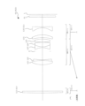
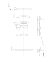
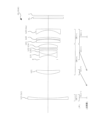
- FIG. 2 is a cross-sectional view showing a lens configuration of an optical system according to a first example.
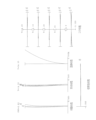
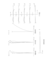
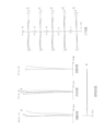
- 5A to 5C are diagrams illustrating various aberrations when the optical system according to the first example is focused on an object at infinity.
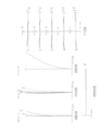
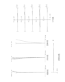
- 5A to 5C are diagrams illustrating various aberrations when the optical system according to the first example is focused on a close object.
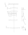
- FIG. 11 is a cross-sectional view showing a lens configuration of an optical system according to a second example.
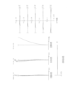
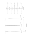
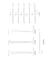
- 13A to 13C are diagrams illustrating various aberrations when the optical system according to the second example is focused on an object at infinity.
- 13A to 13C are diagrams illustrating various aberrations when the optical system according to the second example is focused on a close object.
- FIG. 1 is a cross-sectional view showing a lens configuration of an optical system according to a first example.
- 5A to 5C are diagrams illustrating various aberrations when the optical system according to the first example is focused on a close object.
- FIG. 11 is a cross-sectional view showing a lens configuration of an optical system according to a third example.
- 13A to 13C are diagrams illustrating various aberrations when the optical system according to the third example is focused on an object at infinity.
- 13A to 13C are diagrams illustrating various aberrations when the optical system according to the third example is focused on a close object.
- FIG. 13 is a cross-sectional view showing a lens configuration of an optical system according to a fourth example.
- 13A to 13C are diagrams illustrating various aberrations when the optical system according to Example 4 is focused on an object at infinity.
- 13A to 13C are diagrams illustrating various aberrations when the optical system according to the fourth example is focused on a close object.
- FIG. 13 is a cross-sectional view showing a lens configuration of an optical system according to a fifth example.
- 13A to 13C are diagrams illustrating various aberrations when the optical system according to Example 5 is focused on an object at infinity.
- 13A to 13C are diagrams illustrating various aberrations when the optical system according to the fifth example is focused on a close object.
- FIG. 13 is a cross-sectional view showing a lens configuration of an optical system according to Example 6.
- 13A to 13C are diagrams illustrating various aberrations when the optical system according to Example 6 is focused on an object at infinity.
- 13A to 13C are diagrams illustrating various aberrations when the optical system according to Example 6 is focused on a close object.
- FIG. 13 is a cross-sectional view showing a lens configuration of an optical system according to a seventh example.
- 13A to 13C are diagrams illustrating various aberrations when the optical system according to the seventh example is focused on an object at infinity.
- 13A to 13C are diagrams illustrating various aberrations when the optical system according to the seventh example is focused on a close object.
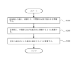
- FIG. 2 is a cross-sectional view of a camera equipped with the optical system. 4 is a flowchart illustrating a method for manufacturing the optical system.
- the optical system OL according to the first embodiment is composed of, in order from the object side, a front group GF, a middle group GM, and a rear group GR, and the middle group GM moves in the optical axis direction during focusing.
- This configuration makes it possible to reduce the weight and size of the optical system OL while ensuring good optical performance at a magnification of 0.5 or more.
- optical system OL Accordingly, it is desirable for the optical system OL according to the first embodiment to satisfy the following conditional expression (1).
- d1 the distance on the optical axis from the lens surface of the front group GF closest to the image surface to the lens surface of the middle group GM closest to the object when focusing on an object at infinity
- f the optical system OL when focusing on an object at infinity
- Conditional formula (1) specifies the ratio of the distance on the optical axis from the lens surface of the front group GF closest to the image surface to the lens surface of the middle group GM closest to the object surface to the focal length of the entire optical system OL when focusing on an object at infinity, that is, the distance between the front group GM and the middle group GM.
- the optical system OL can be made lightweight and compact, and a shooting magnification of 0.5 times or more can be achieved, while providing good aberration correction during focusing. If the upper limit of conditional formula (1) is exceeded, spherical aberration, field curvature, coma aberration, etc.
- conditional formula (1) it is more preferable to set the upper limit of conditional formula (1) to 0.90, 0.85, 0.80, or even 0.75. Furthermore, if the lower limit of conditional expression (1) is exceeded, the optical system OL can be made smaller, but it becomes difficult to correct spherical aberration, curvature of field, coma, and other aberrations during focusing with the middle group GM, which is undesirable. In order to ensure the effect of conditional expression (1), it is more desirable to set the lower limit of conditional expression (1) to 0.58, 0.60, or even 0.63.
- the optical system OL according to the second embodiment is composed of, in order from the object side, a front group GF, a middle group GM, and a rear group GR, and the middle group GM moves in the optical axis direction during focusing.
- This configuration makes it possible to reduce the weight and size of the optical system OL while ensuring good optical performance at a magnification of 0.5 or more.
- optical system OL Accordingly, it is desirable for the optical system OL according to the second embodiment to satisfy the following conditional expression (2).
- TL total optical length (equivalent to air length) of the optical system OL when focused on an object at infinity
- DF the distance on the optical axis from the lens surface in the front group GF closest to the object to the lens surface closest to the image plane
- Conditional formula (2) specifies the ratio of the total optical length of the optical system OL when focusing on an object at infinity to the axial distance from the lens surface of the front group GF closest to the object to the lens surface closest to the image surface (the thickness on the optical axis of the front group GF).
- the thickness on the optical axis of the front group GF (the distance on the optical axis from the lens surface closest to the object to the lens surface closest to the image surface) becomes thicker relative to the total optical length of the optical system OL, so that spherical aberration, chromatic aberration, coma aberration, etc. can be well corrected, but if the total optical length of the optical system OL becomes too short, the occurrence of curvature of field, astigmatism, and coma aberration during focusing becomes large, which is not preferable.
- the thickness on the optical axis of the front group GF becomes thinner relative to the overall optical length of the optical system OL, so the overall optical length of the optical system OL can be shortened, but this is not preferable because aberration correction in the front group GF becomes insufficient and correction of spherical aberration, coma aberration, curvature of field, etc. becomes difficult.
- optical system OL Accordingly, it is desirable for the optical system OL according to the second embodiment to satisfy the following conditional expression (3).
- DM the distance on the optical axis from the lens surface of the intermediate group GM closest to the object to the lens surface closest to the image surface when focusing on an object at infinity
- DR the distance on the optical axis from the lens surface of the rear group GR closest to the object to the lens surface closest to the image surface Distance on the optical axis to the lens surface on the side
- Conditional formula (3) specifies the ratio of the axial distance from the lens surface of the middle group GM closest to the object to the lens surface closest to the image when focusing on an object at infinity (axial thickness of the middle group GM) to the axial distance from the lens surface of the rear group GR closest to the object to the lens surface closest to the image (axial thickness of the rear group GR).
- this conditional formula (3) it is possible to achieve a reduction in weight and size of the optical system OL while providing good aberration correction for brightness and angle of view. If the upper limit of conditional formula (3) is exceeded, the axial thickness of the middle group GM becomes thicker than the axial thickness of the rear group GR, so that spherical aberration, coma aberration, etc.
- conditional formula (3) it is more preferable to set the upper limit of conditional formula (3) to 3.50, 3.00, or even 2.50.
- the axial thickness of the rear group GR becomes thicker than the axial thickness of the middle group GM, which allows for good correction of curvature of field, astigmatism, etc., but when the overall length of the optical system OL is short, it becomes difficult to correct spherical aberration, coma aberration, etc., which are aberrations relative to brightness, so this is not preferred.
- the optical system OL according to the first and second embodiments (hereinafter simply referred to as "the present embodiment") satisfy the following conditional expression (4).
- d1 the distance on the optical axis from the lens surface of the front group GF closest to the image surface to the lens surface of the middle group GM closest to the object when focusing on an object at infinity
- TL the optical system OL when focusing on an object at infinity
- Conditional formula (4) specifies the ratio of the distance on the optical axis from the lens surface of the front group GF closest to the image surface to the lens surface of the middle group GM closest to the object (the distance between the front group GF and the middle group GM) to the total optical length of the optical system OL when focusing on an object at infinity.
- the optical system OL can be made lightweight and compact, and a shooting magnification of 0.5 times or more can be achieved while aberrations during focusing can be corrected well. If the upper limit of conditional formula (4) is exceeded, spherical aberration, curvature of field, coma aberration, etc.
- conditional formula (4) it is more preferable to set the upper limit of conditional formula (4) to 0.38, and even more preferably 0.35. Furthermore, if the lower limit of conditional expression (4) is exceeded, the optical system OL can be made smaller, but it becomes difficult to correct spherical aberration, curvature of field, coma, and other aberrations during focusing in the middle group GM, which is undesirable. In order to ensure the effect of conditional expression (4), it is more desirable to set the lower limit of conditional expression (4) to 0.23, and even more preferably 0.25.
- optical system OL Accordingly, it is desirable for the optical system OL according to this embodiment to satisfy the following conditional expression (5).
- DF the distance on the optical axis from the lens surface of the front group GF closest to the object to the lens surface closest to the image surface
- DM the distance on the optical axis from the lens surface of the intermediate group GM closest to the object to the lens surface closest to the image surface when focusing on an object at infinity
- DR The distance on the optical axis from the lens surface in the rear group GR closest to the object to the lens surface closest to the image plane.
- Conditional expression (5) specifies the ratio of the sum of the axial thicknesses of the front group GF, the middle group GM, and the rear group GR to the axial thickness of the front group GF.
- conditional expression (5) it is more preferable to set the upper limit of conditional expression (5) to 39.00, 38.00, 37.00, or even 36.50. Furthermore, if the lower limit of conditional expression (5) is exceeded, the thickness on the optical axis of the front group GF becomes thicker relative to the overall thickness, and although the curvature of field and astigmatism of the optical system OL can be corrected well, it becomes difficult to correct spherical aberration, coma, etc., which is undesirable. In order to ensure the effect of conditional expression (5), it is more preferable to set the lower limit of conditional expression (5) to 17.50, 18.00, 18.50, or even 18.80.
- optical system OL Accordingly, it is desirable for the optical system OL according to this embodiment to satisfy the following conditional expression (6).
- ⁇ M lateral magnification of the middle group GM when focusing on an object at infinity
- ⁇ R lateral magnification of the rear group GR when focusing on an object at infinity
- Conditional formula (6) specifies the conditions for focusing with the middle group GM.
- the optical system OL can be made lighter and more compact while maintaining the image plane position change during focusing appropriately, and aberration fluctuation during focusing can be suppressed.
- the upper limit of conditional formula (6) is exceeded, the optical system OL can achieve suppression of aberration fluctuation during focusing and compactness, but the image plane position change during focusing becomes large, and the selection of the actuator that operates the middle group GM, which is the focusing group, is restricted, which is not preferable.
- conditional formula (6) In addition, if the lower limit of conditional formula (6) is exceeded, the image plane position change during focusing of the optical system OL becomes small, and the selection of the actuator is less restricted, which is preferable, but it is not preferable because it becomes difficult to suppress aberration fluctuation during focusing and achieve compactness. In order to ensure the effect of conditional expression (6), it is more preferable to set the lower limit of conditional expression (6) to 0.90, 1.00, or even 1.10.
- optical system OL Accordingly, it is desirable for the optical system OL according to this embodiment to satisfy the following conditional expression (7).
- f focal length of the entire optical system OL when focusing on an object at infinity
- fF focal length of the front group GF
- Conditional formula (7) specifies the ratio of the focal length of the entire optical system OL when focusing on an object at infinity to the focal length of the front group GF.
- various aberrations such as spherical aberration, coma aberration, curvature of field, and astigmatism can be effectively corrected in the optical system OL, and aberration fluctuations during focusing can also be effectively suppressed.
- the lens component LL arranged closest to the image plane has negative refractive power. This configuration allows for excellent correction of the field curvature and astigmatism of the optical system OL.
- the front group GF is composed of a single lens. This configuration makes it possible to effectively suppress aberration fluctuations during focusing while achieving a reduction in the weight and size of the optical system OL.
- the optical system OL has a diaphragm (for example, aperture diaphragm S in FIG. 1) in the intermediate group GM, and it is desirable that the diaphragm moves in the optical axis direction during focusing.
- a diaphragm for example, aperture diaphragm S in FIG. 1
- the diaphragm moves in the optical axis direction during focusing.
- the middle group GM it is desirable for the middle group GM to have positive refractive power. This configuration makes it possible to effectively correct various aberrations such as field curvature, spherical aberration, coma, and distortion of the optical system OL.
- the rear group GR it is desirable for the rear group GR to have negative refractive power. This configuration makes it possible to effectively correct various aberrations such as the field curvature, spherical aberration, coma, and distortion of the optical system OL.
- optical system OL Accordingly, it is desirable for the optical system OL according to this embodiment to satisfy the following conditional expression (8).
- fM focal length of the intermediate group GM when focusing on an object at infinity
- f focal length of the entire optical system OL when focusing on an object at infinity
- Conditional expression (8) specifies the ratio of the focal length of the middle group GM to the focal length of the entire optical system OL when focusing on an object at infinity.
- This conditional expression (8) spherical aberration, coma aberration, and the like can be effectively corrected in the optical system OL.
- optical system OL it is desirable for the optical system OL according to this embodiment to satisfy the following conditional expression (9).
- Conditional expression (9) specifies the ratio of the focal length of the rear group GR to the focal length of the entire optical system OL when focusing on an object at infinity.
- This conditional expression (9) it is possible to satisfactorily correct field curvature, lateral chromatic aberration, distortion, and other aberrations in the optical system OL.
- optical system OL Accordingly, it is desirable for the optical system OL according to this embodiment to satisfy the following conditional expression (10).
- Conditional formula (10) specifies the ratio of the focal length of the rear group GR to the focal length of the middle group GM when focusing on an object at infinity. By satisfying this conditional formula (10), it is possible to effectively suppress aberration fluctuations during focusing. If the upper limit of conditional formula (10) is exceeded, the refractive power of the rear group GR is weaker than that of the middle group GM in the optical system OL, and axial chromatic aberration, lateral chromatic aberration, etc. can be effectively corrected, but this is not preferable because the aberration fluctuations during focusing become large. In order to ensure the effect of conditional formula (10), it is more preferable to set the upper limit of conditional formula (10) to 2.90, 2.80, 2.70, or even 2.60.
- conditional formula (10) If the lower limit of conditional formula (10) is exceeded, the refractive power of the rear group GR is stronger than that of the middle group GM in the optical system OL, and it is possible to effectively suppress aberration fluctuations during focusing, but this is not preferable because it becomes difficult to correct axial chromatic aberration, lateral chromatic aberration, etc.
- optical system OL it is desirable for the optical system OL according to this embodiment to satisfy the following conditional expression (11).
- BF Back focus (air equivalent length) of the optical system OL when focusing on an object at infinity
- TL total optical length (equivalent to air length) of the optical system OL when focused on an object at infinity
- Conditional expression (11) specifies the ratio of the back focus to the total optical length of the optical system OL when focusing on an object at infinity. By satisfying this conditional expression (11), it is possible to achieve a reduction in the weight and size of the optical system OL while satisfactorily correcting various aberrations such as spherical aberration and curvature of field. In order to ensure the effect of conditional expression (11), it is more preferable to set the upper limit value of conditional expression (11) to 0.28, and even more preferable to set it to 0.25. In order to ensure the effect of conditional expression (11), it is more preferable to set the lower limit value of conditional expression (11) to 0.11, 0.12, and even more preferable to set it to 0.13.
- optical system OL Accordingly, it is desirable for the optical system OL according to this embodiment to satisfy the following conditional expression (12).
- f focal length of the entire optical system OL when focusing on an object at infinity
- fL1 focal length of the lens component L1 arranged closest to the object
- Conditional expression (12) specifies the ratio of the focal length of the entire optical system OL when focusing on an object at infinity to the focal length of the lens component L1 arranged closest to the object side of the optical system OL.
- various aberrations in the optical system OL such as spherical aberration, coma aberration, curvature of field, and astigmatism, can be effectively corrected, and aberration fluctuations during focusing can be effectively suppressed.
- This camera 1 is a so-called mirrorless camera with interchangeable lenses, which is equipped with the optical system OL according to this embodiment as the photographing lens 2.
- This camera 1 light from an object (subject) (not shown) is collected by the photographing lens 2 and forms a subject image on the imaging surface of the imaging unit 3 via an OLPF (Optical low pass filter) (not shown).
- the subject image is then photoelectrically converted by a photoelectric conversion element (imaging element) provided in the imaging unit 3 to generate an image of the subject.
- This image is displayed on an EVF (Electronic view finder) 4 provided in the camera 1. This allows the photographer to observe the subject through the EVF 4.
- EVF Electronic view finder
- the image photoelectrically converted by the imaging unit 3 is stored in a memory (not shown). In this way, the photographer can photograph the subject using the camera 1.
- the optical system OL according to this embodiment is installed in a single-lens reflex type camera that has a quick-return mirror in the camera body and observes the subject through a viewfinder optical system.
- an optical system OL having a three or four group configuration is shown, but the above configuration conditions can also be applied to other group configurations such as five groups or six groups.
- a configuration in which a lens or lens group is added closest to the object side, or a configuration in which a lens or lens group is added closest to the image surface side is also acceptable.
- a configuration in which a lens group whose position relative to the image surface when focusing is added closest to the image surface side of the optical system OL is considered.
- a lens group refers to a portion having at least one lens separated by an air gap that changes when focusing.
- a lens component refers to a single lens or a cemented lens in which multiple lenses are cemented together.
- a single or multiple lens groups, or a partial lens group may be moved in the optical axis direction to function as a focusing group that focuses from an object at infinity to an object at a close distance.
- the focusing group can also be used for autofocusing, and is suitable for motor drive (such as an ultrasonic motor) for autofocusing.
- the second lens group G2 and the third lens group G3 are used as the focusing group, and it is preferable that the positions of the other lenses relative to the image plane are fixed when focusing.
- a lens group or a partial lens group may be moved so as to have a displacement component perpendicular to the optical axis, or rotated (rocked) in a plane including the optical axis, to serve as an anti-vibration group that corrects image blur caused by camera shake.
- a displacement component perpendicular to the optical axis or rotated (rocked) in a plane including the optical axis, to serve as an anti-vibration group that corrects image blur caused by camera shake.
- at least a part of the second lens group G2 or the third lens group G3 as an anti-vibration group.
- the lens surface may be spherical, flat, or aspherical.
- a spherical or flat lens surface is preferable because it facilitates lens processing and assembly adjustment, and prevents deterioration of optical performance due to errors in processing and assembly adjustment. It is also preferable because there is little deterioration in image performance even if the image plane is misaligned.
- the aspherical surface may be any of the following aspherical surfaces: an aspherical surface formed by grinding, a glass molded aspherical surface in which glass is formed into an aspherical shape using a mold, or a composite aspherical surface in which resin is formed into an aspherical shape on the surface of glass.
- the lens surface may be a diffractive surface, and the lens may be a gradient index lens (GRIN lens) or a plastic lens.
- GRIN lens gradient index lens
- the aperture stop S is preferably located within the intermediate group GM, but it is also possible to use the lens frame to fulfill that role without providing a component serving as an aperture stop.
- each lens surface may be coated with an anti-reflection coating that has high transmittance over a wide wavelength range to reduce flare and ghosting and achieve high-contrast optical performance.
- the front group GF, the middle group GM, and the rear group GR are prepared (step S100).
- the middle group GM is arranged so as to move in the optical axis direction during focusing (step S200), and these lens groups are then arranged so as to satisfy a predetermined condition (for example, the above-mentioned conditional formula (1) in the first embodiment, and the above-mentioned conditional formulas (2) and (3) in the second embodiment) (step S300).
- a predetermined condition for example, the above-mentioned conditional formula (1) in the first embodiment, and the above-mentioned conditional formulas (2) and (3) in the second embodiment
- FIGS. 1, 3, 5, 7, 9, 11, and 13 are cross-sectional views showing the configuration and refractive power distribution of the optical system OL (OL1 to OL7) in each embodiment. Also, at the bottom of the cross-sectional views of these optical systems OL1 to OL7, arrows indicate the direction of movement of each lens group along the optical axis when focusing from an object at infinity ( ⁇ ) to a close object.
- the second-order aspheric coefficient A2 is 0.
- aspheric surfaces are marked with an * to the right of the surface number.
- the first lens group G1 is composed of a meniscus-shaped positive lens L11 (L1) with a convex surface facing the object side.
- the second lens group G2 is composed of, from the object side, a meniscus-shaped negative lens L21 with a convex surface facing the object side, and a meniscus-shaped positive lens L22 with a convex surface facing the object side.
- the third lens group G3 is composed of, from the object side, a biconcave negative lens L31, a meniscus-shaped positive lens L32 with a concave surface facing the object side, and a biconvex positive lens L33.
- the fourth lens group G4 is composed of, from the object side, a biconcave negative lens L41, a meniscus-shaped positive lens L42 with a concave surface facing the object side, and a biconcave negative lens L43 (LL).
- the aperture stop S is disposed between the second lens group G2 and the third lens group G3 in the intermediate group GM.
- the filter group FL is disposed between the fourth lens group G4 and the image plane I.
- the second lens group G2 and the third lens group G3, which are the intermediate group GM move toward the object along the optical axis. Also, when focusing, the aperture stop S moves together with the second lens group G2.
- the values of the specifications of optical system OL1 are listed in Table 1 below.
- f shown in the overall specifications is the focal length of the entire system
- Fno is the F-number
- ⁇ is the half angle of view [°]
- Y is the maximum image height
- TL is the total optical length
- Bf is the back focus, which represent the values when focusing on an object at infinity.
- the back focus Bf indicates the distance on the optical axis from the lens surface closest to the image surface (surface no. 39) to the image surface I.
- the total optical length TL indicates the distance on the optical axis from the lens surface closest to the object (surface no. 1) to the lens surface closest to the image surface (surface no. 39) plus the back focus.
- the first column m in the lens data indicates the order (surface number) of the lens surfaces from the object side along the direction in which the light rays travel
- the second column r indicates the radius of curvature of each lens surface
- the third column d indicates the distance on the optical axis from each optical surface to the next optical surface (surface spacing)
- a radius of curvature of ⁇ indicates a flat surface, and the refractive index of air, 1.00000, has been omitted.
- the lens group focal length indicates the surface number and focal length of the first surface of each lens group.
- the axial air spacing d1 between the first lens group G1 and the second lens group G2, the axial air spacing d2 between the second lens group G2 and the third lens group G3, and the axial air spacing d3 between the third lens group G3 and the fourth lens group G4 change during focusing.
- Table 2 shows the variable spacings when focusing on an object at infinity and when focusing on an object at close range. Note that f is the focal length and ⁇ is the shooting magnification. This explanation is similar in the subsequent examples.
- Figure 2 shows the spherical aberration, astigmatism, distortion, chromatic aberration of magnification, and coma diagrams of this optical system OL1 when focusing on an object at infinity and when focusing on a close object.
- FNo indicates the F-number
- NA indicates the numerical aperture
- Y indicates the image height. Note that in the spherical aberration diagram, the F-number or numerical aperture value corresponding to the maximum aperture is shown, in the astigmatism diagram and the distortion diagram, the maximum value of the image height is shown, and in the coma diagram, the value of each image height is shown.
- the solid line indicates the sagittal image surface
- the dashed line indicates the meridional image surface.
- FIG. 3 is a diagram showing the configuration of an optical system OL2 according to Example 2.
- This optical system OL2 is composed of, in order from the object side, a front group GF consisting of a first lens group G1 having positive refractive power, a middle group GM consisting of a second lens group G2 having positive refractive power, and a rear group GR consisting of a third lens group G3 having negative refractive power.
- the first lens group G1 is composed of a plano-convex positive lens L11 (L1) with its convex surface facing the object side.
- the second lens group G2 is composed of, from the object side, a cemented positive lens formed by cementing a biconvex positive lens L21 and a biconcave negative lens L22, a cemented negative lens formed by cementing a biconcave negative lens L23 and a biconvex positive lens L24, and a biconvex positive lens L25 with an aspheric surface formed on the lens surface on the image side.
- the third lens group G3 is composed of, from the object side, a meniscus positive lens L31 with its concave surface facing the object side, and a biconcave negative lens L32 (LL).
- the aperture stop S is disposed between the negative lens L22 and the negative lens L23 in the second lens group G2, which is the intermediate group GM.
- a filter group FL is disposed between the third lens group G3 and the image plane I.
- the second lens group G2 which is the intermediate group GM, moves toward the object along the optical axis. Also, when focusing, the aperture stop S moves together with the second lens group G2.
- surface 11 is formed to have an aspheric shape.
- Table 4 shows the data for the aspheric surface, i.e., the conic constant K and the values of each of the aspheric constants A4 to A14.
- the axial air distance d1 between the first lens group G1 and the second lens group G2, and the axial air distance d2 between the second lens group G2 and the third lens group G3 change during focusing.
- Table 5 shows the variable distances when focusing on an object at infinity and when focusing on a close object.
- Figure 4 shows diagrams of spherical aberration, astigmatism, distortion, lateral chromatic aberration, and coma aberration for this optical system OL2 when it is focused on an object at infinity and when it is focused on a close object. These aberration diagrams show that this optical system OL2 has excellent imaging performance with various aberrations well corrected.
- FIG. 5 is a diagram showing the configuration of an optical system OL3 according to Example 3.
- This optical system OL3 is composed of, in order from the object side, a front group GF consisting of a first lens group G1, a middle group GM consisting of a second lens group G2 having positive refractive power and a third lens group G3 having positive refractive power, and a rear group GR consisting of a fourth lens group G4 having negative refractive power.
- the first lens group G1 is composed of a parallel plate L11 (L1).
- the second lens group G2 is composed of a cemented positive lens in which a biconvex positive lens L21 and a biconcave negative lens L22 are cemented together, in order from the object side.
- the third lens group G3 is composed of a cemented negative lens in which a biconcave negative lens L31 and a biconvex positive lens L32 are cemented together, and a biconvex positive lens L33 with an aspheric surface formed on the lens surface on the image side, in order from the object side.
- the positive lens L33 is a composite lens in which a resin layer is provided on the image side surface of the glass lens body to form an aspheric surface.
- the fourth lens group G4 is composed of a cemented positive lens in which a biconvex positive lens L41 and a biconcave negative lens L42 are cemented together, in order from the object side, and a biconcave negative lens L43 (LL) with an aspheric surface formed on the lens surface on the object side.
- the negative lens L43 is a composite lens in which a resin layer is provided on the image-side surface of the glass lens body to form an aspheric surface.
- the aperture stop S is disposed between the second lens group G2 and the third lens group G3 in the intermediate group GM.
- the filter group FL is disposed between the fourth lens group G4 and the image plane I.
- the second lens group G2 and the third lens group G3, which are the intermediate group GM, move toward the object along the optical axis. Also, when focusing, the aperture stop S moves together with the third lens group G3.
- surfaces 12 and 16 are aspheric.
- Table 7 below shows the aspheric data, i.e., the conic constant K and the values of each of the aspheric constants A4 to A14.
- the axial air distance d1 between the first lens group G1 and the second lens group G2, the axial air distance d2 between the second lens group G2 and the third lens group G3, and the axial air distance d3 between the third lens group G3 and the fourth lens group G4 change during focusing.
- Table 8 shows the variable distances when focusing on an object at infinity and when focusing on a close-up object.
- Figure 6 shows diagrams of spherical aberration, astigmatism, distortion, chromatic aberration of magnification, and coma for this optical system OL3 when focused on an object at infinity and when focused on a close object. These aberration diagrams show that this optical system OL3 has excellent imaging performance with various aberrations well corrected.
- [Fourth embodiment] 7 is a diagram showing the configuration of an optical system OL4 according to Example 4.
- This optical system OL4 is composed of, in order from the object side, a front group GF consisting of a first lens group G1 having negative refractive power, a middle group GM consisting of a second lens group G2 having positive refractive power, and a rear group GR consisting of a third lens group G3 having negative refractive power.
- the first lens group G1 is composed of a meniscus-shaped negative lens L11 (L1) with a convex surface facing the object side.
- the second lens group G2 is composed of, from the object side, a meniscus-shaped positive lens L21 with a convex surface facing the object side, a cemented negative lens formed by cementing a biconcave negative lens L22 and a biconvex positive lens L23, and a biconvex positive lens L24 with an aspheric surface formed on the lens surface on the image side.
- the positive lens L24 is a composite lens in which a resin layer is provided on the image side surface of a glass lens body to form an aspheric surface.
- the third lens group G3 is composed of, from the object side, a meniscus-shaped positive lens L31 with a concave surface facing the object side, and a meniscus-shaped negative lens L32 (LL) with a concave surface facing the object side.
- the aperture stop S is disposed between the positive lens L21 and the negative lens L22 in the second lens group G2, which is the intermediate group GM.
- a filter group FL is disposed between the third lens group G3 and the image plane I.
- the second lens group G2 which is the intermediate group GM, moves toward the object along the optical axis. Also, when focusing, the aperture stop S moves together with the second lens group G2.
- Table 9 lists the specifications of optical system OL4.
- surface 11 is formed to have an aspheric shape.
- Table 10 shows the data for the aspheric surface, i.e., the conic constant K and the values of each of the aspheric constants A4 to A14.
- the axial air distance d1 between the first lens group G1 and the second lens group G2, and the axial air distance d2 between the second lens group G2 and the third lens group G3 change during focusing.
- Table 11 shows the variable distances when focusing on an object at infinity and when focusing on a close object.
- Figure 8 shows diagrams of spherical aberration, astigmatism, distortion, lateral chromatic aberration, and coma aberration for this optical system OL4 when it is focused on an object at infinity and when it is focused on a close object. These aberration diagrams show that this optical system OL4 has excellent imaging performance with various aberrations well corrected.
- FIG. 9 is a diagram showing the configuration of an optical system OL5 according to Example 5.
- This optical system OL5 is composed of, in order from the object side, a front group GF consisting of a first lens group G1 having negative refractive power, a middle group GM consisting of a second lens group G2 having positive refractive power, and a rear group GR consisting of a third lens group G3 having negative refractive power.
- the first lens group G1 is composed of a meniscus-shaped negative lens L11 (L1) with a convex surface facing the object side.
- the second lens group G2 is composed of, in order from the object side, a meniscus-shaped positive lens L21 with a convex surface facing the object side, a meniscus-shaped negative lens L22 with a convex surface facing the object side and with aspheric surfaces formed on the object side lens surface and the image plane lens surface, a cemented positive lens consisting of a biconcave negative lens L23 and a biconvex positive lens L24, and a meniscus-shaped positive lens L25 with a concave surface facing the object side.
- the third lens group G3 is composed of a meniscus-shaped positive lens L31 with a concave surface facing the object side, and a meniscus-shaped negative lens L32 (LL) with a concave surface facing the object side.
- the aperture stop S is disposed between the negative lens L22 and the negative lens L23 in the second lens group G2, which is the intermediate group GM.
- a filter group FL is disposed between the third lens group G3 and the image plane I.
- the second lens group G2 which is the intermediate group GM, moves toward the object along the optical axis. Also, when focusing, the aperture stop S moves together with the second lens group G2.
- Table 12 lists the specifications of the optical system OL5.
- the fifth and sixth surfaces are aspheric.
- the following Table 13 shows the aspheric data, i.e., the conic constant K and the values of each of the aspheric constants A4 to A14.
- the axial air distance d1 between the first lens group G1 and the second lens group G2, and the axial air distance d2 between the second lens group G2 and the third lens group G3 change during focusing.
- Table 14 shows the variable distances when focusing on an object at infinity and when focusing on a close object.
- Figure 10 shows diagrams of spherical aberration, astigmatism, distortion, lateral chromatic aberration, and coma aberration for this optical system OL5 when focused on an object at infinity and when focused on a close object. These aberration diagrams show that this optical system OL5 has excellent imaging performance with various aberrations well corrected.
- FIG. 11 is a diagram showing the configuration of an optical system OL6 according to Example 6.
- This optical system OL6 is composed of, in order from the object side, a front group GF consisting of a first lens group G1 having negative refractive power, a middle group GM consisting of a second lens group G2 having positive refractive power and a third lens group G3 having positive refractive power, and has positive refractive power as a whole, and a rear group GR consisting of a fourth lens group G4 having negative refractive power.
- the first lens group G1 is composed of a plano-concave negative lens L11 (L1) with a flat surface facing the object side.
- the second lens group G2 is composed of a meniscus positive lens L21 with a convex surface facing the object side.
- the third lens group G3 is composed of, from the object side, a cemented negative lens formed by cementing a biconcave negative lens L31 and a biconvex positive lens L32, a meniscus positive lens L33 with a concave surface facing the object side and an aspheric surface formed on the lens surface on the image side, and a biconvex positive lens L34.
- the fourth lens group G4 is composed of, from the object side, a meniscus positive lens L41 with a concave surface facing the object side, a meniscus negative lens L42 with a concave surface facing the object side and an aspheric surface formed on the lens surface on the object side, and a meniscus negative lens L43 (LL) with a concave surface facing the object side.
- the second lens group G2 and the third lens group G3, which are the intermediate group GM move toward the object along the optical axis. Also, when focusing, the aperture stop S moves together with the third lens group G3.
- surfaces 10 and 15 are aspheric.
- Table 16 below shows the aspheric data, i.e., the conic constant K and the values of each of the aspheric constants A4 to A14.
- the axial air distance d1 between the first lens group G1 and the second lens group G2, the axial air distance d2 between the second lens group G2 and the third lens group G3, and the axial air distance d3 between the third lens group G3 and the fourth lens group G4 change during focusing.
- Table 17 shows the variable distances when focusing on an object at infinity and when focusing on a close-up object.
- FIG. 13 is a diagram showing the configuration of an optical system OL7 according to Example 7.
- This optical system OL7 is composed of, in order from the object side, a front group GF consisting of a first lens group G1 having negative refractive power, a middle group GM consisting of a second lens group G2 having positive refractive power and a third lens group G3 having positive refractive power, and has positive refractive power as a whole, and a rear group GR consisting of a fourth lens group G4 having negative refractive power.
- the first lens group G1 is composed of a plano-concave negative lens L11 (L1) with a flat surface facing the object side.
- the second lens group G2 is composed of a meniscus positive lens L21 with a convex surface facing the object side.
- the third lens group G3 is composed of, from the object side, a cemented negative lens formed by cementing a biconcave negative lens L31 and a biconvex positive lens L32, a meniscus positive lens L33 with a concave surface facing the object side and an aspheric lens surface on the image side, and a biconvex positive lens L34.
- the fourth lens group G4 is composed of, from the object side, a meniscus positive lens L41 with a concave surface facing the object side, and a biconcave negative lens L42 (LL).
- the aperture stop S is disposed between the second lens group G2 and the third lens group G3 in the intermediate group GM.
- the filter group FL is disposed between the fourth lens group G4 and the image plane I.
- the axial air distance d1 between the first lens group G1 and the second lens group G2, the axial air distance d2 between the second lens group G2 and the third lens group G3, and the axial air distance d3 between the third lens group G3 and the fourth lens group G4 change during focusing.
- the following Table 20 shows the variable distances when focusing on an object at infinity and when focusing on a close-up object.
- Figure 14 shows diagrams of spherical aberration, astigmatism, distortion, lateral chromatic aberration, and coma aberration for this optical system OL7 when it is focused on an object at infinity and when it is focused on a close object. These aberration diagrams show that this optical system OL7 has excellent imaging performance with various aberrations well corrected.
Landscapes
- Physics & Mathematics (AREA)
- General Physics & Mathematics (AREA)
- Optics & Photonics (AREA)
- Lenses (AREA)
Abstract
Description
0.54 < d1/f < 1.00
但し、
d1:無限遠物体合焦時の前記前群の最も像面側のレンズ面から前記中間群の最も物体側のレンズ面までの光軸上の距離
f:無限遠物体合焦時の前記光学系の全系の焦点距離
32.00 < TL/DF < 80.00
1.00 < DM/DR < 4.00
但し、
TL:無限遠物体合焦時の前記光学系の光学全長
DF:前記前群の最も物体側のレンズ面から最も像面側のレンズ面までの光軸上の距離
DM:無限遠物体合焦時の前記中間群の最も物体側のレンズ面から最も像面側のレンズ面までの光軸上の距離
DR:前記後群の最も物体側のレンズ面から最も像面側のレンズ面までの光軸上の距離
第1の実施形態に係る光学系OLは、図1に示すように、物体側から順に、前群GFと、中間群GMと、後群GRとから構成され、合焦時に、中間群GMが光軸方向に移動する。この構成により、光学系OLの軽量化、小型化を達成しつつ、撮影倍率が0.5倍以上で、良好な光学性能を確保することができる。
但し、
d1:無限遠物体合焦時の前群GFの最も像面側のレンズ面から中間群GMの最も物体側のレンズ面までの光軸上の距離
f:無限遠物体合焦時の光学系OLの全系の焦点距離
第2の実施形態に係る光学系OLは、図1に示すように、物体側から順に、前群GFと、中間群GMと、後群GRとから構成され、合焦時に、中間群GMが光軸方向に移動する。この構成により、光学系OLの軽量化、小型化を達成しつつ、撮影倍率が0.5倍以上で、良好な光学性能を確保することができる。
但し、
TL:無限遠物体合焦時の光学系OLの光学全長(空気換算長)
DF:前群GFの最も物体側のレンズ面から最も像面側のレンズ面までの光軸上の距離
但し、
DM:無限遠物体合焦時の中間群GMの最も物体側のレンズ面から最も像面側のレンズ面までの光軸上の距離
DR:後群GRの最も物体側のレンズ面から最も像面側のレンズ面までの光軸上の距離
但し、
d1:無限遠物体合焦時の前群GFの最も像面側のレンズ面から中間群GMの最も物体側のレンズ面までの光軸上の距離
TL:無限遠物体合焦時の光学系OLの光学全長(空気換算長)
但し、
DF:前群GFの最も物体側のレンズ面から最も像面側のレンズ面までの光軸上の距離
DM:無限遠物体合焦時の中間群GMの最も物体側のレンズ面から最も像面側のレンズ面までの光軸上の距離
DR:後群GRの最も物体側のレンズ面から最も像面側のレンズ面までの光軸上の距離
但し、
βM:無限遠物体合焦時の中間群GMの横倍率
βR:無限遠物体合焦時の後群GRの横倍率
但し、
f:無限遠物体合焦時の光学系OLの全系の焦点距離
fF:前群GFの焦点距離
但し、
fM:無限遠物体合焦時の中間群GMの焦点距離
f:無限遠物体合焦時の光学系OLの全系の焦点距離
但し、
fR:後群GRの焦点距離
f:無限遠物体合焦時の光学系OLの全系の焦点距離
但し、
fR:後群GRの焦点距離
fM:無限遠物体合焦時の中間群GMの焦点距離
但し、
BF:無限遠物体合焦時の光学系OLのバックフォーカス(空気換算長)
TL:無限遠物体合焦時の光学系OLの光学全長(空気換算長)
但し、
f:無限遠物体合焦時の光学系OLの全系の焦点距離
fL1:最も物体側に配置されたレンズ成分L1の焦点距離
+A4×y4+A6×y6+A8×y8
+A10×y10+A12×y12+A14×y14 (a)
図1は、第1実施例に係る光学系OL1の構成を示す図である。この光学系OL1は、物体側から順に、正の屈折力を有する第1レンズ群G1からなる前群GFと、正の屈折力を有する第2レンズ群G2及び正の屈折力を有する第3レンズ群G3からなり、全体で正の屈折力を有する中間群GMと、負の屈折力を有する第4レンズ群G4からなる後群GRとから構成されている。
[全体諸元]
f = 39.532
Fno = 2.82
ω[°] = 19.04
Y = 14.200
TL = 91.000
TL(空気換算長)= 90.455
BF = 13.600
BF(空気換算長)= 13.055
[レンズデータ]
m r d nd νd
物面 ∞
1 100.0000 2.5000 1.48749 70.32
2 200.0000 d1
3 17.1714 1.2000 1.62299 58.12
4 13.6956 8.9068
5 22.4494 4.1000 1.60311 60.69
6 152.7709 5.5226
7 ∞ d2 開口絞りS
8 -33.8144 1.0000 1.84666 23.80
9 40.4635 0.9000
10 -127.9705 2.5000 1.65160 58.57
11 -21.7834 0.1000
12 32.3448 4.1000 1.80610 40.98
13 -52.6084 d3
14 -135.7811 1.0000 1.48749 70.32
15 34.0082 1.5713
16 -593.0949 3.4000 1.77250 49.62
17 -27.6401 6.2884
18 -16.5865 1.2000 1.51680 64.13
19 214.0528 10.5000
20 ∞ 1.6000 1.51680 64.13
21 ∞ 1.5000
像面 ∞
[レンズ群焦点距離]
レンズ群 始面 焦点距離
前群GF (第1レンズ群G1) 1 406.931
中間群GM 3 27.854
第2レンズ群G2 3 61.926
第3レンズ群G3 8 36.238
後群GR (第4レンズ群G4) 14 -43.251
[可変間隔データ]
無限遠物体 近距離物体
f 39.532 -
β - -1.00
d1 28.0111 1.5000
d2 3.5000 8.4471
d3 1.6000 23.1639
図3は、第2実施例に係る光学系OL2の構成を示す図である。この光学系OL2は、物体側から順に、正の屈折力を有する第1レンズ群G1からなる前群GFと、正の屈折力を有する第2レンズ群G2からなる中間群GMと、負の屈折力を有する第3レンズ群G3からなる後群GRとから構成されている。
[全体諸元]
f = 41.335
Fno = 2.07
ω[°] = 18.39
Y = 14.200
TL = 85.800
TL(空気換算長)= 85.255
BF = 13.600
BF(空気換算長)= 13.055
[レンズデータ]
m r d nd νd
物面 ∞
1 500.0000 2.0000 1.48749 70.32
2 ∞ d1
3 28.1947 4.6000 1.71999 50.27
4 -61.1236 1.0000 1.80100 34.92
5 74.1433 9.0000
6 ∞ 4.0000 開口絞りS
7 -17.6671 1.0000 1.62588 35.72
8 17.0726 5.0000 1.80400 46.60
9 -46.4184 0.1000
10 79.5479 3.3000 1.62263 58.16
11* -30.3176 d2
12 -36.8461 3.0000 1.78590 44.17
13 -25.0125 7.6000
14 -16.0825 1.2000 1.48749 70.32
15 401.0302 10.5000
16 ∞ 1.6000 1.51680 64.13
17 ∞ 1.5000
像面 ∞
[レンズ群焦点距離]
レンズ群 始面 焦点距離
前群GF (第1レンズ群G1) 1 1025.662
中間群GM(第2レンズ群G2) 3 33.624
後群GR (第3レンズ群G3) 12 -53.277
[非球面データ]
第11面
K=1.00000
A4 = 3.71185E-05 A6 =-6.46471E-07 A8 = 3.01332E-08
A10=-7.16019E-10 A12= 8.76060E-12 A14= 4.29930E-14
[可変間隔データ]
無限遠物体 近距離物体
f 41.335 -
β - -1.00
d1 28.8000 1.3000
d2 1.6000 29.1000
図5は、第3実施例に係る光学系OL3の構成を示す図である。この光学系OL3は、物体側から順に、第1レンズ群G1からなる前群GFと、正の屈折力を有する第2レンズ群G2及び正の屈折力を有する第3レンズ群G3からなり、全体で正の屈折力を有する中間群GMと、負の屈折力を有する第4レンズ群G4からなる後群GRとから構成されている。
[全体諸元]
f = 35.500
Fno = 1.86
ω[°] = 21.09
Y = 14.200
TL = 81.000
TL(空気換算長)= 80.455
BF = 13.400
BF(空気換算長)= 12.855
[レンズデータ]
m r d nd νd
物面 ∞
1 ∞ 1.2000 1.48749 70.32
2 ∞ d1
3 32.3113 4.8000 1.70000 48.10
4 -44.7976 1.0000 1.83400 37.18
5 292.5746 d2
6 ∞ 4.5000 開口絞りS
7 -16.1414 1.0000 1.71736 29.57
8 40.2209 3.8000 1.80400 46.60
9 -38.4171 0.1000
10 110.7728 3.8000 1.80400 46.60
11 -25.6333 0.2000 1.56093 36.64
12* -25.6333 d3
13 355.6821 5.0000 1.88300 40.66
14 -18.2588 1.0000 1.58144 40.98
15 95.1472 4.8661
16* -20.1725 0.2000 1.56093 36.64
17 -18.0890 1.0000 1.51742 52.20
18 337.3157 10.3000
19 ∞ 1.6000 1.51680 64.13
20 ∞ 1.5000
像面 ∞
[レンズ群焦点距離]
レンズ群 始面 焦点距離
前群GF (第1レンズ群G1) 1 ∞
中間群GM 3 32.878
第2レンズ群G2 3 61.694
第3レンズ群G3 7 40.089
後群GR (第4レンズ群G4) 13 -84.292
[非球面データ]
第12面
K=1.00000
A4 = 2.46184E-05 A6 =-2.41773E-07 A8 = 1.11585E-08
A10=-2.69002E-10 A12= 3.24180E-12 A14= 1.52330E-14
第16面
K=1.00000
A4 =-3.88298E-05 A6 = 1.22826E-07 A8 =-2.32494E-09
A10= 9.49732E-12 A12= 0.00000E+00 A14= 0.00000E+00
[可変間隔データ]
無限遠物体 近距離物体
f 35.500 -
β - -0.70
d1 24.8000 2.6000
d2 8.5000 9.3828
d3 1.8340 23.1512
図7は、第4実施例に係る光学系OL4の構成を示す図である。この光学系OL4は、物体側から順に、負の屈折力を有する第1レンズ群G1からなる前群GFと、正の屈折力を有する第2レンズ群G2からなる中間群GMと、負の屈折力を有する第3レンズ群G3からなる後群GRとから構成されている。
[全体諸元]
f = 38.000
Fno = 2.86
ω[°] = 20.18
Y = 14.200
TL = 81.000
TL(空気換算長)= 80.455
BF = 14.300
BF(空気換算長)= 13.755
[レンズデータ]
m r d nd νd
物面 ∞
1 1000.0000 1.2000 1.67270 32.19
2 341.6032 d1
3 26.3938 2.5000 1.61800 63.34
4 104.4847 10.8000
5 ∞ 3.0000 開口絞りS
6 -12.9734 1.0000 1.71736 29.57
7 35.4454 3.4000 1.80400 46.60
8 -33.7721 0.1000
9 128.6034 3.5000 1.79500 45.31
10 -20.4927 0.2000 1.56093 36.64
11* -20.4927 d2
12 -30.0289 2.2000 1.74950 35.25
13 -23.0492 9.5978
14 -16.3907 1.2000 1.60311 60.69
15 -110.6686 11.2000
16 ∞ 1.6000 1.51680 64.13
17 ∞ 1.5000
像面 ∞
[レンズ群焦点距離]
レンズ群 始面 焦点距離
前群GF (第1レンズ群G1) 1 -771.847
中間群GM(第2レンズ群G2) 3 30.796
後群GR (第3レンズ群G3) 12 -47.477
[非球面データ]
第11面
K=1.00000
A4 = 3.47586E-05 A6 =-1.66949E-07 A8 = 5.09420E-09
A10=-4.45933E-11 A12= 0.00000E+00 A14= 0.00000E+00
[可変間隔データ]
無限遠物体 近距離物体
f 38.000 -
β - -1.00
d1 26.4022 1.6000
d2 1.6000 26.4022
図9は、第5実施例に係る光学系OL5の構成を示す図である。この光学系OL5は、物体側から順に、負の屈折力を有する第1レンズ群G1からなる前群GFと、正の屈折力を有する第2レンズ群G2からなる中間群GMと、負の屈折力を有する第3レンズ群G3からなる後群GRとから構成されている。
[全体諸元]
f = 38.257
Fno = 2.88
ω[°] = 20.21
Y = 14.200
TL = 81.000
TL(空気換算長)= 80.455
BF = 15.800
BF(空気換算長)= 15.255
[レンズデータ]
m r d nd νd
物面 ∞
1 1000.0000 1.2000 1.62299 58.12
2 191.9205 d1
3 21.6636 3.2000 1.61800 63.34
4 85.8643 3.9234
5* 5000.0000 1.2000 1.53504 55.71
6* 111.0085 5.4408
7 ∞ 2.5000 開口絞りS
8 -13.9656 1.0000 1.75520 27.57
9 70.8048 3.7000 1.80400 46.60
10 -16.9076 0.1000
11 -1132.4588 2.7000 1.80610 40.98
12 -34.9496 d2
13 -33.0000 2.2000 1.69895 30.13
14 -23.5462 8.6359
15 -16.7498 1.2000 1.62299 58.12
16 -115.9839 12.7000
17 ∞ 1.6000 1.51680 64.13
18 ∞ 1.5000
像面 ∞
[レンズ群焦点距離]
レンズ群 始面 焦点距離
前群GF (第1レンズ群G1) 1 -381.447
中間群GM(第2レンズ群G2) 3 30.882
後群GR (第3レンズ群G3) 13 -48.278
[非球面データ]
第 5面
K=1.00000
A4 = 2.14608E-04 A6 =-6.37110E-07 A8 = 4.09234E-09
A10= 0.00000E+00 A12= 0.00000E+00 A14= 0.00000E+00
第 6面
K=1.00000
A4 = 2.71565E-04 A6 =-6.66060E-07 A8 = 1.26067E-08
A10= 0.00000E+00 A12= 0.00000E+00 A14= 0.00000E+00
[可変間隔データ]
無限遠物体 近距離物体
f 38.257 -
β - -1.00
d1 26.6000 1.6000
d2 1.6000 26.6000
図11は、第6実施例に係る光学系OL6の構成を示す図である。この光学系OL6は、物体側から順に、負の屈折力を有する第1レンズ群G1からなる前群GFと、正の屈折力を有する第2レンズ群G2及び正の屈折力を有する第3レンズ群G3からなり、全体で正の屈折力を有する中間群GMと、負の屈折力を有する第4レンズ群G4からなる後群GRとから構成されている。
[全体諸元]
f = 34.506
Fno = 1.87
ω[°] = 22.613
Y = 14.200
TL = 81.000
TL(空気換算長)= 80.455
BF = 13.100
BF(空気換算長)= 12.555
[レンズデータ]
m r d nd νd
物面 ∞
1 ∞ 1.2000 1.60342 38.03
2 137.0000 d1
3 29.7763 3.5000 1.77250 49.62
4 162.6784 d2
5 ∞ 3.9000 開口絞りS
6 -17.7201 1.0000 1.69895 30.13
7 18.8264 3.6000 1.80400 46.60
8 -368.3266 1.3000
9 -70.0000 1.2000 1.53504 55.71
10* -63.1478 0.1000
11 73.4674 3.8000 1.80400 46.60
12 -24.0859 d3
13 -512.8175 3.0000 1.77250 49.62
14 -53.8371 0.4000
15* -52.0000 1.5000 1.53504 55.71
16 -55.8074 6.8350
17 -18.5196 1.2000 1.51742 52.20
18 -421.4731 10.0000
19 ∞ 1.6000 1.51680 64.13
20 ∞ 1.5000
像面 ∞
[レンズ群焦点距離]
レンズ群 始面 焦点距離
前群GF (第1レンズ群G1) 1 -227.039
中間群GM 3 33.771
第2レンズ群G2 3 46.646
第3レンズ群G3 6 43.983
後群GR (第4レンズ群G4) 13 -82.053
[非球面データ]
第10面
K=1.00000
A4 = 4.22622E-05 A6 =-2.61315E-07 A8 = 1.23491E-08
A10=-2.58085E-10 A12= 2.70030E-12 A14=-1.11010E-14
第15面
K=1.00000
A4 = 7.42581E-06 A6 = 4.99661E-08 A8 =-2.94414E-10
A10= 1.20068E-12 A12= 0.00000E+00 A14= 0.00000E+00
[可変間隔データ]
無限遠物体 近距離物体
f 34.506 -
β - -0.70
d1 23.1650 1.6000
d2 10.6000 8.6232
d3 1.6000 25.1418
図13は、第7実施例に係る光学系OL7の構成を示す図である。この光学系OL7は、物体側から順に、負の屈折力を有する第1レンズ群G1からなる前群GFと、正の屈折力を有する第2レンズ群G2及び正の屈折力を有する第3レンズ群G3からなり、全体で正の屈折力を有する中間群GMと、負の屈折力を有する第4レンズ群G4からなる後群GRとから構成されている。
[全体諸元]
f = 34.809
Fno = 1.88
ω[°] = 22.33
Y = 14.200
TL = 81.000
TL(空気換算長)= 80.455
BF = 13.100
BF(空気換算長)= 12.555
[レンズデータ]
m r d nd νd
物面 ∞
1 ∞ 1.2000 1.60342 38.03
2 137.0000 d1
3 30.2634 3.5000 1.77250 49.62
4 163.9532 d2
5 ∞ 3.9000 開口絞りS
6 -17.5242 1.0000 1.69895 30.13
7 19.2332 3.6000 1.80400 46.60
8 -338.5777 1.3000
9 -70.0000 1.2000 1.53504 55.71
10* -59.8040 0.1000
11 78.4773 3.8000 1.80400 46.60
12 -23.8412 d3
13 -125.6395 3.0000 1.77250 49.62
14 -46.8274 8.9114
15 -23.0295 1.2000 1.51742 52.20
16 237.4580 10.0000
17 ∞ 1.6000 1.51680 64.13
18 ∞ 1.5000
像面 ∞
[レンズ群焦点距離]
レンズ群 始面 焦点距離
前群GF (第1レンズ群G1) 1 -227.039
中間群GM 3 34.000
第2レンズ群G2 3 47.502
第3レンズ群G3 6 44.102
後群GR (第4レンズ群G4) 13 -82.712
[非球面データ]
第10面
K=1.00000
A4 = 4.27018E-05 A6 =-3.39344E-07 A8 = 1.47524E-08
A10=-2.99211E-10 A12= 3.04550E-12 A14=-1.22760E-14
[可変間隔データ]
無限遠物体 近距離物体
f 34.809 -
β - -0.70
d1 22.9886 1.6000
d2 10.6000 8.3141
d3 1.6000 25.2745
第1実施例~第7実施例における条件式(1)~(12)の対応値を以下の表21に示す。
(1)d1/f
(2)TL/DF
(3)DM/DR
(4)d1/TL
(5)(DF+DM+DR)/DF
(6)(1-βM2)×βR2
(7)f/fF
(8)fM/f
(9)(-fR)/f
(10)(-fR)/fM
(11)BF/TL
(12)f/fL1
第1実施例 第2実施例 第3実施例 第4実施例
(1) 0.709 0.697 0.699 0.695
(2) 36.182 42.627 67.046 67.046
(3) 2.365 2.373 2.296 1.885
(4) 0.310 0.338 0.308 0.328
(5) 19.116 20.900 34.138 32.248
(6) 1.732 1.462 1.166 1.581
(7) 0.097 0.040 0.000 -0.049
(8) 0.705 0.813 0.926 0.810
(9) 1.094 1.289 2.374 1.249
(10) 1.553 1.585 2.564 1.542
(11) 0.144 0.153 0.160 0.171
(12) 0.097 0.040 0.000 -0.049
第5実施例 第6実施例 第7実施例
(1) 0.695 0.671 0.660
(2) 67.046 67.046 67.046
(3) 1.974 2.242 2.212
(4) 0.331 0.288 0.286
(5) 30.833 35.946 36.093
(6) 1.634 1.133 1.135
(7) -0.100 -0.152 -0.153
(8) 0.807 0.979 0.977
(9) 1.262 2.378 2.376
(10) 1.563 2.430 2.433
(11) 0.190 0.156 0.156
(12) -0.100 -0.152 -0.153
GF 前群 GM 中間群 GR 後群
S 開口絞り(絞り)
Claims (19)
- 物体側から順に、前群と、中間群と、後群とから構成され、
合焦時に、前記中間群が光軸方向に移動し、
次式の条件を満足する光学系。
0.54 < d1/f < 1.00
但し、
d1:無限遠物体合焦時の前記前群の最も像面側のレンズ面から前記中間群の最も物体側のレンズ面までの光軸上の距離
f:無限遠物体合焦時の前記光学系の全系の焦点距離 - 物体側から順に、前群と、中間群と、後群とから構成され、
合焦時に、前記中間群が光軸方向に移動し、
次式の条件を満足する光学系。
32.00 < TL/DF < 80.00
1.00 < DM/DR < 4.00
但し、
TL:無限遠物体合焦時の前記光学系の光学全長
DF:前記前群の最も物体側のレンズ面から最も像面側のレンズ面までの光軸上の距離
DM:無限遠物体合焦時の前記中間群の最も物体側のレンズ面から最も像面側のレンズ面までの光軸上の距離
DR:前記後群の最も物体側のレンズ面から最も像面側のレンズ面までの光軸上の距離 - 次式の条件を満足する請求項1または2に記載の光学系。
0.20 < d1/TL < 0.40
但し、
d1:無限遠物体合焦時の前記前群の最も像面側のレンズ面から前記中間群の最も物体側のレンズ面までの光軸上の距離
TL:無限遠物体合焦時の前記光学系の光学全長 - 次式の条件を満足する請求項1~3のいずれか一項に記載の光学系。
17.00 < (DF+DM+DR)/DF < 40.00
但し、
DF:前記前群の最も物体側のレンズ面から最も像面側のレンズ面までの光軸上の距離
DM:無限遠物体合焦時の前記中間群の最も物体側のレンズ面から最も像面側のレンズ面までの光軸上の距離
DR:前記後群の最も物体側のレンズ面から最も像面側のレンズ面までの光軸上の距離 - 次式の条件を満足する請求項1~4のいずれか一項に記載の光学系。
0.80 < (1-βM2)×βR2 < 2.00
但し、
βM:無限遠物体合焦時の前記中間群の横倍率
βR:無限遠物体合焦時の前記後群の横倍率 - 次式の条件を満足する請求項1~5のいずれか一項に記載の光学系。
-0.50 < f/fF < 0.30
但し、
f:無限遠物体合焦時の前記光学系の全系の焦点距離
fF:前記前群の焦点距離 - 最も像面側に配置されたレンズ成分は、負の屈折力を有する請求項1~6のいずれか一項に記載の光学系。
- 前記前群は、1つのレンズで構成されている請求項1~7のいずれか一項に記載の光学系。
- 前記中間群内に絞りを有し、
合焦時に、前記絞りが光軸方向に移動する請求項1~8のいずれか一項に記載の光学系。 - 前記中間群は、正の屈折力を有する請求項1~9のいずれか一項に記載の光学系。
- 前記後群は、負の屈折力を有する請求項1~10のいずれか一項に記載の光学系。
- 次式の条件を満足する請求項1~11のいずれか一項に記載の光学系。
0.50 < fM/f < 1.10
但し、
fM:無限遠物体合焦時の前記中間群の焦点距離
f:無限遠物体合焦時の前記光学系の全系の焦点距離 - 次式の条件を満足する請求項1~12のいずれか一項に記載の光学系。
0.50 < (-fR)/f < 3.00
但し、
fR:前記後群の焦点距離
f:無限遠物体合焦時の前記光学系の全系の焦点距離 - 次式の条件を満足する請求項1~13のいずれか一項に記載の光学系。
1.00 < (-fR)/fM < 3.00
但し、
fR:前記後群の焦点距離
fM:無限遠物体合焦時の前記中間群の焦点距離 - 次式の条件を満足する請求項1~14のいずれか一項に記載の光学系。
0.10 < BF/TL < 0.30
但し、
BF:無限遠物体合焦時の前記光学系のバックフォーカス
TL:無限遠物体合焦時の前記光学系の光学全長 - 次式の条件を満足する請求項1~15のいずれか一項に記載の光学系。
-0.40 < f/fL1 < 0.30
但し、
f:無限遠物体合焦時の前記光学系の全系の焦点距離
fL1:最も物体側に配置されたレンズ成分の焦点距離 - 請求項1~16のいずれか一項に記載の光学系を有する光学機器。
- 物体側から順に、前群と、中間群と、後群とから構成された光学系の製造方法であって、
合焦時に、前記中間群が光軸方向に移動するように配置し、
次式の条件を満足するように配置する光学系の製造方法。
0.54 < d1/f < 1.00
但し、
d1:無限遠物体合焦時の前記前群の最も像面側のレンズ面から前記中間群の最も物体側のレンズ面までの光軸上の距離
f:無限遠物体合焦時の前記光学系の全系の焦点距離 - 物体側から順に、前群と、中間群と、後群とから構成された光学系の製造方法であって、
合焦時に、前記中間群が光軸方向に移動するように配置し、
次式の条件を満足するように配置する光学系の製造方法。
32.00 < TL/DF < 80.00
1.00 < DM/DR < 4.00
但し、
TL:無限遠物体合焦時の前記光学系の光学全長
DF:前記前群の最も物体側のレンズ面から最も像面側のレンズ面までの光軸上の距離
DM:無限遠物体合焦時の前記中間群の最も物体側のレンズ面から最も像面側のレンズ面までの光軸上の距離
DR:前記後群の最も物体側のレンズ面から最も像面側のレンズ面までの光軸上の距離
Priority Applications (2)
| Application Number | Priority Date | Filing Date | Title |
|---|---|---|---|
| JP2025510207A JPWO2024203170A5 (ja) | 2024-03-08 | 光学系及び光学機器 | |
| CN202480005379.7A CN120303598A (zh) | 2023-03-27 | 2024-03-08 | 光学系统、光学设备以及光学系统的制造方法 |
Applications Claiming Priority (2)
| Application Number | Priority Date | Filing Date | Title |
|---|---|---|---|
| JP2023-049774 | 2023-03-27 | ||
| JP2023049774 | 2023-03-27 |
Publications (1)
| Publication Number | Publication Date |
|---|---|
| WO2024203170A1 true WO2024203170A1 (ja) | 2024-10-03 |
Family
ID=92904254
Family Applications (1)
| Application Number | Title | Priority Date | Filing Date |
|---|---|---|---|
| PCT/JP2024/009075 Ceased WO2024203170A1 (ja) | 2023-03-27 | 2024-03-08 | 光学系、光学機器及び光学系の製造方法 |
Country Status (2)
| Country | Link |
|---|---|
| CN (1) | CN120303598A (ja) |
| WO (1) | WO2024203170A1 (ja) |
Citations (5)
| Publication number | Priority date | Publication date | Assignee | Title |
|---|---|---|---|---|
| JPH04304408A (ja) * | 1991-04-01 | 1992-10-27 | Nikon Corp | 水中カメラ用レンズ |
| JPH06308383A (ja) * | 1993-04-23 | 1994-11-04 | Nikon Corp | 水中カメラ用中望遠レンズ |
| JP2013235239A (ja) * | 2012-04-12 | 2013-11-21 | Konica Minolta Inc | マクロレンズおよび撮像装置 |
| JP2014197128A (ja) * | 2013-03-29 | 2014-10-16 | キヤノン株式会社 | レンズ装置及びそれを有する撮像装置 |
| JP2016156941A (ja) * | 2015-02-24 | 2016-09-01 | 株式会社ニコン | レンズ系、光学機器及びレンズ系の製造方法 |
-
2024
- 2024-03-08 CN CN202480005379.7A patent/CN120303598A/zh active Pending
- 2024-03-08 WO PCT/JP2024/009075 patent/WO2024203170A1/ja not_active Ceased
Patent Citations (5)
| Publication number | Priority date | Publication date | Assignee | Title |
|---|---|---|---|---|
| JPH04304408A (ja) * | 1991-04-01 | 1992-10-27 | Nikon Corp | 水中カメラ用レンズ |
| JPH06308383A (ja) * | 1993-04-23 | 1994-11-04 | Nikon Corp | 水中カメラ用中望遠レンズ |
| JP2013235239A (ja) * | 2012-04-12 | 2013-11-21 | Konica Minolta Inc | マクロレンズおよび撮像装置 |
| JP2014197128A (ja) * | 2013-03-29 | 2014-10-16 | キヤノン株式会社 | レンズ装置及びそれを有する撮像装置 |
| JP2016156941A (ja) * | 2015-02-24 | 2016-09-01 | 株式会社ニコン | レンズ系、光学機器及びレンズ系の製造方法 |
Also Published As
| Publication number | Publication date |
|---|---|
| CN120303598A (zh) | 2025-07-11 |
| JPWO2024203170A1 (ja) | 2024-10-03 |
Similar Documents
| Publication | Publication Date | Title |
|---|---|---|
| CN110573924B (zh) | 变倍光学系统、光学装置和制造变倍光学系统的方法 | |
| CN102037388B (zh) | 变焦透镜、具有其的光学设备及变焦透镜的制造方法 | |
| CN104797969B (zh) | 变倍光学系统、光学装置和制造变倍光学系统的方法 | |
| CN110520777B (zh) | 变倍光学系统、光学装置和制造变倍光学系统的方法 | |
| JP7677390B2 (ja) | 光学系及び光学機器 | |
| JP5493308B2 (ja) | ズームレンズ系、及び、このズームレンズ系を備えた光学機器 | |
| CN116324567B (zh) | 变倍光学系统、光学设备及变倍光学系统的制造方法 | |
| JP7821409B2 (ja) | 変倍光学系及び光学機器 | |
| CN110494786B (zh) | 变倍光学系统、光学装置和制造变倍光学系统的方法 | |
| CN108604003A (zh) | 变焦镜头、光学设备以及变焦镜头的制造方法 | |
| JP7627444B2 (ja) | 光学系及び光学機器 | |
| JP5407363B2 (ja) | 変倍光学系、撮像装置、変倍光学系の製造方法 | |
| JP2025119019A (ja) | 変倍光学系及び光学機器 | |
| CN110546544B (zh) | 变倍光学系统、光学装置和制造变倍光学系统的方法 | |
| WO2024142829A1 (ja) | 光学系、光学機器及び光学系の製造方法 | |
| WO2024053269A1 (ja) | 変倍光学系、光学機器、および変倍光学系の製造方法 | |
| JP2016156941A (ja) | レンズ系、光学機器及びレンズ系の製造方法 | |
| JP7254271B2 (ja) | 変倍光学系、光学機器 | |
| CN107615130A (zh) | 变倍光学系统、光学设备以及变倍光学系统的制造方法 | |
| JP2025052870A (ja) | 光学系、光学機器、および光学系の製造方法 | |
| JP6349801B2 (ja) | ズームレンズ、光学装置 | |
| JP6070055B2 (ja) | 変倍光学系、光学装置、変倍光学系の製造方法 | |
| JP5407364B2 (ja) | 変倍光学系、撮像装置、変倍光学系の製造方法 | |
| JP7526394B2 (ja) | 変倍光学系及び光学機器 | |
| CN104755986B (zh) | 可变放大率光学系统、光学装置,和用于可变放大率光学系统的生产方法 |
Legal Events
| Date | Code | Title | Description |
|---|---|---|---|
| 121 | Ep: the epo has been informed by wipo that ep was designated in this application |
Ref document number: 24779301 Country of ref document: EP Kind code of ref document: A1 |
|
| WWE | Wipo information: entry into national phase |
Ref document number: 202480005379.7 Country of ref document: CN |
|
| WWE | Wipo information: entry into national phase |
Ref document number: 2025510207 Country of ref document: JP |
|
| WWP | Wipo information: published in national office |
Ref document number: 202480005379.7 Country of ref document: CN |
|
| NENP | Non-entry into the national phase |
Ref country code: DE |
|
| 122 | Ep: pct application non-entry in european phase |
Ref document number: 24779301 Country of ref document: EP Kind code of ref document: A1 |