WO2024203004A1 - 自律移動体及び動作制御方法 - Google Patents
自律移動体及び動作制御方法 Download PDFInfo
- Publication number
- WO2024203004A1 WO2024203004A1 PCT/JP2024/008175 JP2024008175W WO2024203004A1 WO 2024203004 A1 WO2024203004 A1 WO 2024203004A1 JP 2024008175 W JP2024008175 W JP 2024008175W WO 2024203004 A1 WO2024203004 A1 WO 2024203004A1
- Authority
- WO
- WIPO (PCT)
- Prior art keywords
- action
- base
- motion
- moving body
- autonomous
- Prior art date
- Legal status (The legal status is an assumption and is not a legal conclusion. Google has not performed a legal analysis and makes no representation as to the accuracy of the status listed.)
- Ceased
Links
Images






Classifications
-
- A—HUMAN NECESSITIES
- A63—SPORTS; GAMES; AMUSEMENTS
- A63H—TOYS, e.g. TOPS, DOLLS, HOOPS OR BUILDING BLOCKS
- A63H11/00—Self-movable toy figures
-
- B—PERFORMING OPERATIONS; TRANSPORTING
- B25—HAND TOOLS; PORTABLE POWER-DRIVEN TOOLS; MANIPULATORS
- B25J—MANIPULATORS; CHAMBERS PROVIDED WITH MANIPULATION DEVICES
- B25J13/00—Controls for manipulators
-
- B—PERFORMING OPERATIONS; TRANSPORTING
- B25—HAND TOOLS; PORTABLE POWER-DRIVEN TOOLS; MANIPULATORS
- B25J—MANIPULATORS; CHAMBERS PROVIDED WITH MANIPULATION DEVICES
- B25J5/00—Manipulators mounted on wheels or on carriages
Definitions
- This technology relates to an autonomous moving body and a method for controlling its movement, and in particular to an autonomous moving body and a method for controlling its movement that enhances expressiveness.
- Patent Document 1 In recent years, attempts have been made to improve the expressiveness of communication robots capable of communicating with users (see, for example, Patent Document 1).
- the dog-type robot can give a paw when asked to do so, or bark "woof" when it sees a person.
- the combination of conditions and actions is one-to-one, or at most one-to-several, so the robot's actions tend to be monotonous. Also, even if other conditions are met while playing a certain action, the robot cannot move on to the next action until the action being played has been stopped, so the transitions between actions become visible.
- This technology was developed in light of these circumstances, and aims to enhance the expressiveness of autonomous mobile objects such as communication robots.
- An autonomous moving body includes a motion planning unit that creates a motion plan, and a motion control unit that executes a superimposed motion, which is a motion in which an expression corresponding to at least one of the surrounding situation and the autonomous body's own state is superimposed on a base motion, which is a motion based on the motion plan, during the execution of the base motion.
- a movement control method creates a motion plan for an autonomous mobile body, and while performing a base motion, which is a motion based on the motion plan, causes the autonomous mobile body to perform a superimposed motion, which is a motion in which an expression corresponding to at least one of the surroundings of the autonomous mobile body and the state of the autonomous mobile body is superimposed on the base motion.
- an operation plan for an autonomous mobile body is created, and while a base operation, which is an operation based on the operation plan, is being performed, the autonomous mobile body executes a superimposed operation, which is an operation in which an expression corresponding to at least one of the surrounding situation of the autonomous mobile body and the state of the autonomous mobile body is superimposed on the base operation.
- FIG. 1 is a perspective view of an autonomous moving body to which the present technology is applied.
- 1 is a diagram illustrating a configuration example of an actuator included in an autonomous moving body.
- 2 is a block diagram showing an example of the functional configuration of the autonomous mobile body motion control system; 4 is a block diagram showing an example of a functional configuration of an operation control unit;
- FIG. 11 is a timing chart for explaining an example of an operation of an autonomous moving body with respect to an object of interest.
- FIG. 13 is a diagram showing an example of a dog lying down position.
- FIG. 1 is a diagram for explaining an example of a method for controlling the operation of an autonomous moving body.
- 1 is a timing chart for explaining a conventional method for controlling the operation of an autonomous moving body.
- 1 is a timing chart for explaining a method for controlling the operation of an autonomous moving body to which the present technology is applied.
- 1 is a timing chart for explaining a method for controlling the operation of an autonomous moving body to which the present technology is applied.
- FIG. 1 is a block diagram illustrating an example of the configuration of a computer.
- FIG. 1 is a perspective view of an autonomous moving body 11.
- FIG. 1 also shows an example of the configuration of a display and a sensor provided on the autonomous moving body 11.
- the autonomous mobile body 11 is a dog-type quadruped robot that includes a head 21, a body 22, four legs 23fl to 23hr, and a tail 24.
- legs 23 when there is no need to distinguish between the legs 23fl to 23hr, they will simply be referred to as legs 23.
- the autonomous moving body 11 is equipped with two displays, a display 51L and a display 51R, on the head 21.
- a display 51L and a display 51R on the head 21.
- the display 51 when there is no need to distinguish between the display 51L and the display 51R, they will simply be referred to as the display 51.
- Each display 51 has a function of visually expressing the eye movements and emotions of the autonomous moving body 11.
- each display 51 can express the movements of the eyeballs, pupils, and eyelids according to emotions and actions, producing natural movements close to those of real animals such as dogs, and can express the line of sight and emotions of the autonomous moving body 11 with high precision and flexibility.
- the user can intuitively grasp the state of the autonomous moving body 11 from the eye movements displayed on the display 51.
- the autonomous moving body 11 also includes various sensors.
- the autonomous moving body 11 includes a microphone 52, a camera 53, a ToF (Time Of Flight) sensor 54, a human presence sensor 55, a distance measurement sensor 56, a touch sensor 57, an illuminance sensor 58, leg sensors 59fl to 59hr, and an IMU (inertial measurement unit) 60.
- a microphone 52 for example, the autonomous moving body 11 includes a microphone 52, a camera 53, a ToF (Time Of Flight) sensor 54, a human presence sensor 55, a distance measurement sensor 56, a touch sensor 57, an illuminance sensor 58, leg sensors 59fl to 59hr, and an IMU (inertial measurement unit) 60.
- leg sensors 59 when there is no need to individually distinguish between the leg sensors 59fl to 59hr, they will simply be referred to as leg sensors 59.
- the autonomous mobile body 11 has, for example, four microphones 52 on the head 21.
- Each microphone 52 collects surrounding sounds including, for example, the user's speech and surrounding environmental sounds. Furthermore, by having multiple microphones 52, it becomes possible to collect surrounding sounds with high sensitivity and to localize the sound source.
- the autonomous mobile body 11 is equipped with two wide-angle cameras 53, for example, at the nose and waist, which capture images of the autonomous mobile body 11's surroundings.
- the camera 53 located at the nose captures images within the autonomous mobile body 11's forward field of view (i.e., the dog's field of view).
- the camera 53 located at the waist captures images of the surroundings centered around the upper part of the autonomous mobile body 11.
- the autonomous mobile body 11 can extract feature points of the ceiling, for example, based on images captured by the camera 53 located at the waist, and achieve SLAM (Simultaneous Localization and Mapping).
- SLAM Simultaneous Localization and Mapping
- the ToF sensor 54 is provided, for example, at the tip of the nose, and detects the distance to an object present in front of the head 21.
- the ToF sensor 54 enables the autonomous mobile body 11 to detect the distance to various objects with high accuracy, and can realize operations according to the relative position to targets including the user, obstacles, etc.
- the human presence sensor 55 is placed, for example, on the chest and detects the location of the user or a pet kept by the user. By detecting an animal object in front of the autonomous mobile body 11 using the human presence sensor 55, the autonomous mobile body 11 can realize various actions toward the animal object, such as actions corresponding to emotions such as interest, fear, or surprise.
- the distance measurement sensor 56 is placed, for example, on the chest and detects the condition of the floor surface in front of the autonomous mobile body 11.
- the distance measurement sensor 56 allows the autonomous mobile body 11 to accurately detect the distance to an object present on the floor surface in front of it, and to realize operations according to the relative position of the object.
- the touch sensor 57 is arranged in areas where the user is likely to touch the autonomous moving body 11, such as the top of the head, under the chin, and on the back, and detects contact (touch) by the user.
- the touch sensor 57 is composed of, for example, a capacitive or pressure-sensitive touch sensor.
- the autonomous moving body 11 can detect contact actions by the user, such as touching, stroking, tapping, and pushing, using the touch sensor 57, and can perform an action according to the contact action.
- by arranging the touch sensor 57 in a line or a plane on each part it becomes possible to detect the position touched within each part.
- the illuminance sensor 58 is disposed, for example, at the base of the tail 24 on the back of the head 21, and detects the illuminance of the space in which the autonomous mobile body 11 is located.
- the autonomous mobile body 11 can detect the surrounding brightness using the illuminance sensor 58 and perform an operation according to the brightness.
- Each leg sensor 59 is disposed at a location corresponding to the pad of the foot (sole) at the tip of each leg 23.
- Each leg sensor 59 is, for example, a load sensor or force sensor, and detects the load on each leg 23.
- the IMU 60 is placed, for example, in each of predetermined locations (e.g., the head 21 and torso 22) and detects physical quantities such as the speed, acceleration, and rotation of each location.
- the IMU 60 is composed of a six-axis sensor that detects acceleration and angular velocity along the X-axis, Y-axis, and Z-axis.
- the IMU 60 enables the autonomous mobile body 11 to accurately detect the movement of the head 21 and torso 22, and realize operation control according to the situation.
- the configuration of the sensors equipped in the autonomous mobile body 11 can be flexibly changed depending on the specifications, operation, etc.
- the autonomous mobile body 11 may further include various communication devices including a temperature sensor, a geomagnetic sensor, and a GNSS (Global Navigation Satellite System) signal receiver.
- GNSS Global Navigation Satellite System
- FIG. 2 shows an example of the configuration of the joints of the autonomous mobile body 11. More specifically, FIG. 2 shows an example of the configuration of actuators that drive the joints of the autonomous mobile body 11.
- the autonomous moving body 11 includes actuators 71A, 71B, 71C, 71D, 71Efl to 71Ehr, 71Ffl to 71Fhr, and 71Gfl to 71Ghr.
- actuator 71Efl to 71Ehr when there is no need to distinguish between actuators 71Efl to 71Ehr, they will simply be referred to as actuator 71E.
- actuator 71F when there is no need to distinguish between actuators 71Ffl to 71Fhr, they will simply be referred to as actuator 71F.
- actuator 71Gfl to 71Ghr when there is no need to distinguish between actuators 71Gfl to 71Ghr, they will simply be referred to as actuator 71G.
- actuator 71A to 71G when there is no need to distinguish between actuators 71A to 71G, they will simply be referred to as actuator 71.
- Each actuator 71 is, for example, a servo motor.
- Actuator 71A is a two-axis actuator that controls the movement (rotation) of head 21 around the roll axis and pitch axis.
- Actuator 71B is a single-axis actuator that controls the movement (rotation) of the head 21 around the yaw axis.
- Actuator 71C is a single-axis actuator that controls the movement (rotation) of the neck around the pitch axis.
- Actuator 71D is a single-axis actuator that controls the movement (rotation) of tail section 24 around the pitch axis.
- Actuator 71Efl is a single-axis actuator that controls the movement (rotation) of the shoulder joint of leg 23fl around the pitch axis.
- Actuator 71Ffl is a single-axis actuator that controls the movement (rotation) of the shoulder joint of leg 23fl around the roll axis.
- Actuator 71Gfl is a single-axis actuator that controls the movement (rotation) of the elbow joint of leg 23fl around the pitch axis.
- Actuator 71Efr is a single-axis actuator that controls the movement (rotation) of the shoulder joint of leg 23fr around the pitch axis.
- Actuator 71Ffr is a single-axis actuator that controls the movement (rotation) of the shoulder joint of leg 23fr around the roll axis.
- Actuator 71Gfr is a single-axis actuator that controls the movement (rotation) of the elbow joint of leg 23fr around the pitch axis.
- Actuator 71Ehl is a single-axis actuator that controls the movement (rotation) of the hip joint of leg 23hl around the pitch axis.
- Actuator 71Fhl is a single-axis actuator that controls the movement (rotation) of the hip joint of leg 23hl around the roll axis.
- Actuator 71Ghl is a single-axis actuator that controls the movement (rotation) of the knee joint of leg 23hl around the pitch axis.
- Actuator 71Ehr is a single-axis actuator that controls the movement (rotation) of the hip joint of leg 23hr around the pitch axis.
- Actuator 71Fhr is a single-axis actuator that controls the movement (rotation) of the hip joint of leg 23hr around the roll axis.
- Actuator 71Ghr is a single-axis actuator that controls the movement (rotation) of the knee joint of leg 23hr around the pitch axis.
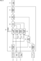
- FIG. 3 shows the configuration of a motion control system 101 that controls the motion of the autonomous moving body 11 .
- the motion control system 101 includes a servo encoder 111, a parameter memory unit 112, a control unit 113, and a servo control unit 114.
- the servo encoder 111 is provided for each actuator 71, for example. Each servo encoder 111 detects the rotational angle of each actuator 71, thereby detecting the rotational angle of each joint of the autonomous mobile body 11 (hereinafter referred to as the joint angle). Each servo encoder 111 generates a signal indicating the detection result of the joint angle of each joint (hereinafter referred to as the joint angle detection signal), and supplies it to the control unit 113.
- the parameter storage unit 112 stores self-parameters that indicate the state of the autonomous mobile body 11.
- the self-parameters include the attributes of the autonomous mobile body 11 (age (operating period), gender, etc.), bone structure, physical strength, fatigue level, personality, emotions, interests, etc.
- the self-parameters in the parameter storage unit 112 are updated and referenced by the control unit 113 as appropriate.
- the control unit 113 includes an instinct unit 121 and a rational unit 122.
- the instinct unit 121 mainly controls the instinctive behavior of the autonomous mobile body 11.
- the instinct unit 121 includes a perception unit 131 and a motion control unit 132, and is responsible for perception processing and motion control processing.
- the rational unit 122 mainly controls the rational behavior of the autonomous mobile body 11.
- the rational unit 122 includes a recognition unit 141, an intellectual processing unit 142, and an action planning unit 143, and is responsible for recognition processing, intellectual processing, action planning processing, etc.
- the instinctive behavior and rational behavior of the autonomous mobile body 11 are not necessarily clearly separated, and there may be cases where the instinct unit 121 controls part of the rational behavior and the rational unit 122 controls part of the instinctive behavior.
- the perception unit 131 includes various sensors such as the microphone 52, camera 53, ToF sensor 54, human presence sensor 55, distance measurement sensor 56, touch sensor 57, illuminance sensor 58, leg sensor 59, and IMU 60 shown in FIG. 1.
- the perception unit 131 perceives the situation around the autonomous mobile body 11 and the state of the autonomous mobile body 11 based on external world information and internal information of the autonomous mobile body 11.
- the situation around the autonomous mobile body 11 includes, for example, stimuli provided to at least one of the autonomous mobile body 11's vision, hearing, and touch.
- the perception unit 131 supplies perception information indicating the perception results of the situation around the autonomous mobile body 11 and the state of the autonomous mobile body 11 to the operation control unit 132 and the recognition unit 141.
- the recognition unit 141 performs more advanced recognition processing than the perception unit 131 based on the perception information, and recognizes the situation around the autonomous mobile body 11 and the state of the autonomous mobile body 11 in more detail.
- the recognition unit 141 supplies recognition information indicating the recognition results of the situation around the autonomous mobile body 11 and the state of the autonomous mobile body 11 to the intelligent processing unit 142.
- the intellectual processing unit 142 executes intellectual processing based on the recognition information, and supplies intellectual processing information indicating the results of the execution of the intellectual processing to the operation planning unit 143.
- the motion planning unit 143 creates a motion plan for the autonomous mobile body 11 based on the intelligent processing information, and supplies motion plan information indicating the created motion plan to the motion control unit 132.
- the motion control unit 132 controls the motion of the autonomous mobile body 11 based on the joint angle detection signal from the servo encoder 111, the self parameters stored in the parameter storage unit 112, the perception information from the perception unit 131, and the motion plan information from the motion plan unit 143. For example, as described below, the motion control unit 132 controls the motion of the autonomous mobile body 11 so as to execute a reflex action that reflexively responds to the situation around the autonomous mobile body 11 and the state of the autonomous mobile body 11 while continuing the motion based on the motion plan by the rational unit 122 without stopping.
- the motion control unit 132 generates information indicating the target values of the joint angles of each joint of the autonomous mobile body 11 (hereinafter referred to as joint angle plan information) and supplies it to the servo control unit 114.
- the servo control unit 114 controls each actuator 71 that drives each joint of the autonomous mobile body 11 based on the joint angle planning information, and controls the joint angle of each joint.
- FIG. 4 shows an example of the configuration of the operation control unit 132 in FIG.
- the movement control unit 132 includes a movement plan interpretation unit 161, a base movement control unit 162, an additional movement control unit 163, a breathing movement control unit 164, a forward kinematics analysis unit 165, a posture estimation unit 166, a basic posture control unit 167, a superposition unit 168, a posture stabilization unit 169, and an inverse kinematics analysis unit 170.
- the motion plan interpretation unit 161 interprets the motion plan information supplied from the motion planning unit 143, and supplies motion plan interpretation information indicating the interpretation results to the base motion control unit 162 and the basic posture control unit 167.
- the base movement control unit 162 controls movements that are the basis of movements to be executed based on the movement plan (hereinafter referred to as base movements) based on the movement plan interpretation information.
- the base movements are, for example, the minimum movements required to realize the movements planned by the movement planning unit 143. Therefore, the parts (for example, joints) used in the base movements are kept to a minimum, and are usually limited to certain parts rather than the entire body.
- the base action may be realized by a preset action that is designed in advance by a developer and preset in the autonomous mobile body 11, or may be realized by an action (hereinafter referred to as a generated action) that is dynamically generated by calculation in response to at least one of the circumstances surrounding the autonomous mobile body 11 and the state of the autonomous mobile body 11.
- the base movement control unit 162 generates information required to execute a base movement (hereinafter referred to as base movement information) based on the movement plan interpretation information.
- the base movement information includes, for example, control information required to execute a base movement (for example, information indicating the movement of each joint).
- the base movement control unit 162 supplies the base movement information to the superimposition unit 168.
- the additional action control unit 163 controls the action (hereinafter, additional action) to be added to express at least one of the emotions and states of the autonomous mobile body 11 based on the perception information from the perception unit 131 and the self-parameters stored in the parameter storage unit 112.
- the additional action control unit 163 plans an expression to be superimposed on the base action of the autonomous moving body 11 based on the perception information and the autonomous moving body's own parameters. That is, the additional action control unit 163 plans an expression to be superimposed on the base action of the autonomous moving body 11 based on at least one of the situation around the autonomous moving body 11 and the state of the autonomous moving body 11.
- the additional action control unit 163 generates information (hereinafter referred to as additional action information) required to execute an additional action for superimposing a planned expression on a base action.
- the additional action information includes, for example, control information required to execute the additional action (for example, information indicating the movement of each joint).
- the additional action control unit 163 supplies the additional action information to the superimposing unit 168.
- One of the additional actions is an action in which the autonomous mobile body 11 expresses interest in an object of interest (hereinafter referred to as an interest action).
- an interest action an action in which the autonomous mobile body 11 expresses interest in an object of interest
- an interest action an action in which the autonomous mobile body 11 expresses interest in an object of interest
- reaction action for each interest and a duration of interest for each interest are set.
- the i-th element of each array, the object of interest Ii, the reaction action Ri, and the duration Ti correspond to each other. That is, the reaction action Ri is executed for the object of interest Ii, and the interest continues for the duration Ti.
- the autonomous mobile body 11 is controlled to show interest in the object of interest with a higher priority.
- the interest of the autonomous mobile body 11 is set to the object of interest I2. That is, the autonomous mobile body 11 is controlled to execute a reaction action R2 corresponding to the object of interest I2 and to follow the object of interest I2 for a duration T2.
- following an object of interest includes, for example, actions such as continuing to gaze at the object of interest or continuing to chase the object of interest.
- the autonomous mobile body 11 is controlled to execute a reaction action R1 corresponding to the object of interest I1 and follow the object of interest I1 for the duration T1.
- array I[n] and array R[n] are set as follows:
- the autonomous mobile body 11 finds the user, it gazes at the user in a cozy manner, and when it finds the ball along the way, it chases after it while sniffing it.
- the ball has a higher priority than the user, and basically, the autonomous mobile body 11's interest may shift from the user to the ball along the way, but it never shifts from the ball to the user along the way.
- the breathing action control unit 164 controls the breathing action that expresses the breathing of the autonomous moving body 11 based on the self parameters stored in the parameter storage unit 112.
- the breathing action is, for example, an up and down movement that imitates breathing, or an expanding action that is periodically performed by a hardware configuration.
- the period and vibration of the breathing action are set, for example, based on a function that uses self-parameters. Note that the period of the breathing action may be shortened, for example, after the autonomous mobile body 11 has engaged in vigorous exercise, or when the temperature (body temperature) of the autonomous mobile body 11 is high, etc.
- the breathing movement control unit 164 generates information (hereinafter referred to as breathing movement information) necessary to execute a breathing movement with a set period and vibration.
- the breathing movement information includes, for example, control information (e.g., information indicating the movement of each joint) necessary to execute a breathing movement.
- the breathing movement control unit 164 supplies the breathing movement information to the superimposition unit 168.
- the forward kinematics analysis unit 165 detects the position and orientation of each joint of the autonomous mobile body 11 based on the joint angle detection signals from each servo encoder 111.
- the forward kinematics analysis unit 165 generates information indicating the detection results of the position and orientation of each joint of the autonomous mobile body 11 (hereinafter referred to as joint position information) and supplies it to the orientation estimation unit 166.
- the attitude estimation unit 166 estimates the attitude of the autonomous mobile body 11 as a whole and each part based on the inertial measurement signals from each IMU 60 included in the perception unit 131 and the joint position detection information from the forward kinematics analysis unit 165.
- the attitude estimation unit 166 generates information indicating the estimation result of the attitude of the autonomous mobile body 11 (hereinafter referred to as attitude estimation information) and supplies it to the basic attitude control unit 167 and the attitude stabilization unit 169.
- the basic posture control unit 167 controls the operation of expressing the basic posture (hereinafter referred to as the basic posture) in the base operation of the autonomous mobile body 11 based on the motion plan interpretation information, posture estimation information, and the self-parameters stored in the parameter storage unit 112.
- the basic posture control unit 167 recognizes the basic posture in the base movement of the autonomous mobile body 11 based on the motion plan interpretation information.
- the basic posture is, for example, sitting, lying down, etc.
- the basic posture control unit 167 sets values of adjustment parameters such as the ground contact position and center of gravity of each leg 23 relative to the basic posture based on the posture estimation information and self-parameters. For example, the basic posture control unit 167 may set a predetermined offset value as the value of the adjustment parameter, or may set the value of the adjustment parameter using a function based on self-parameters (e.g., bone structure, fatigue level, personality, emotions, etc.).
- self-parameters e.g., bone structure, fatigue level, personality, emotions, etc.
- each dog has a different posture when lying down (e.g., the posture of each leg), and the autonomous moving body 11 also expresses the individuality of each dog's basic posture based on the adjustment parameters.
- the basic posture control unit 167 may add a time element to the function that sets the value of the adjustment parameter, thereby changing the value of the adjustment parameter in the time direction.
- the basic posture control unit 167 may cause the value of the adjustment parameter to fluctuate over time, or may change the value of the adjustment parameter significantly and irregularly, simulating the physical strain that maintaining the same posture places on the body. This causes the basic posture to change in the time direction.
- the range of adjustment parameters (for example, the area that can be adjusted in a basic pose) is defined for each basic pose.
- the basic posture control unit 167 generates information required to assume a basic posture corresponding to a base movement (hereinafter referred to as basic posture information).
- the basic posture information includes, for example, control information required to execute the basic posture (for example, information indicating the movement of each joint, adjustment parameters, etc.).
- the basic posture control unit 167 supplies the basic posture information to the superimposition unit 168.
- the superimposition unit 168 superimposes the movements of the autonomous mobile body 11 based on the base movement information, additional movement information, breathing movement information, and basic posture information, thereby superimposing expressions corresponding to the situation around the autonomous mobile body 11 and the state of the autonomous mobile body 11 onto the base movements.
- the superimposed expressions represent, for example, the emotions and state of the autonomous mobile body 11. This allows, for example, the reaction of the autonomous mobile body 11 to external stimuli, personality, etc. to be expressed.
- the superimposition unit 168 superimposes an additional movement based on the additional movement information, a breathing movement based on the breathing movement information, and a movement for taking a basic posture based on basic posture information (hereinafter referred to as a basic posture movement) onto a base movement based on the base movement information.
- a basic posture movement a movement for taking a basic posture based on basic posture information
- Non-base movements are, for example, movements that are dynamically executed in response to the situation around the autonomous mobile body 11 and the state of the autonomous mobile body 11 while the base movements are being performed, in other words, movements that react to the situation around the autonomous mobile body 11 and the state of the autonomous mobile body 11.
- each non-base operation may be realized by a preset operation or a generated operation.
- the superimposition unit 168 generates information (hereinafter referred to as superimposed motion information) necessary to execute the motion after superimposition (hereinafter referred to as superimposed motion).
- the superimposed motion information includes, for example, control information (e.g., information indicating the movement of each joint) necessary to execute the superimposed motion.
- the superimposition unit 168 supplies the superimposed motion information to the posture stabilization unit 169.
- the posture stabilization unit 169 performs posture stabilization processing on the superimposed motion based on the posture estimation information and the superimposed motion information. That is, the posture stabilization unit 169 adjusts the superimposed motion so that the posture of the autonomous moving body 11 is stabilized when the superimposed motion is executed. In other words, the posture stabilization unit 169 superimposes an operation that stabilizes the posture of the autonomous moving body 11 (hereinafter referred to as a posture stabilization operation) on the superimposed motion.
- a posture stabilization operation an operation that stabilizes the posture of the autonomous moving body 11
- the posture stabilization process includes, for example, a process for preventing the autonomous moving body 11 from tipping over (hereinafter referred to as tipping prevention process), and a process for preventing interference between parts of the autonomous moving body 11 (hereinafter referred to as interference prevention process).
- the anti-tip process is, for example, a process that keeps the center of gravity of the autonomous mobile body 11 balanced so that it does not tip over, and performs a defensive action in the event that it does tip over. For example, if the autonomous mobile body 11 attempts to move its head 21 forward while keeping its legs 23fr raised through a superimposed motion, it may lose balance and tip forward.
- the posture stabilization unit 169 calculates the ZMP (Zero Moment Point) of the autonomous mobile body 11, etc., and corrects the trajectory of the superimposed motion as necessary.
- ZMP Zero Moment Point
- the interference prevention process is, for example, a process for preventing collisions or contacts between each part (e.g., each joint, etc.) of the autonomous mobile body 11. For example, if the autonomous mobile body 11 attempts to turn the head 21 to the right with the leg 23fr raised through a superimposed motion, there is a possibility that the nose tip of the head 21 will collide with the leg 23fr. In response to this, the posture stabilization unit 169 calculates the distance between each part of the autonomous mobile body 11, etc., and corrects the trajectory of the superimposed motion as necessary.
- the posture stabilization unit 169 generates information (hereinafter referred to as stabilized superimposed motion information) required to execute the superimposed motion after posture stabilization processing (hereinafter referred to as stabilized superimposed motion).
- the stabilized superimposed motion information includes, for example, control information (e.g., information indicating the movement of each joint) required to execute the stabilized superimposed motion.
- the posture stabilization unit 169 supplies the stabilized superimposed motion information to the inverse kinematics analysis unit 170.
- Each motion has a layer structure as shown in Fig. 7.
- the motions are arranged in the order of posture stabilization motion, breathing motion, basic posture motion, additional motion, and base motion.
- Posture stabilization movements include, for example, movements to keep the center of gravity balanced so as not to fall, movements to take a defensive stance if one falls, movements to avoid injuring oneself (preventing contact between body parts), etc.
- Respiratory movements include, for example, the movement of breathing.
- Basic posture movements include, for example, movements that change posture, movements that lose posture, and swaying movements.
- Additional actions include, for example, actions of looking at (the direction of) sudden movements or sounds in the surroundings, actions of looking at something that has newly captured the user's interest or becoming bored with it, actions of continuing to gaze at an object of interest, etc.
- the base actions include, for example, actions such as going to look for food, giving a paw to the user, and acting happy when the user pets the robot.
- the operation of the autonomous mobile body 11 is executed so that the higher-level operation subsumes the lower-level operation as much as possible.
- the lower-level operation and the higher-level operation are executed in parallel.
- each operation is not necessarily executed in the same way as if it were operating independently. In other words, the operations are adjusted as necessary so that they are executed smoothly in parallel.
- a lower-level action and a higher-level action interfere with each other and cannot be executed in parallel, for example, the action with the higher priority is executed first.
- a case in which a lower-level action and a higher-level action interfere with each other and cannot be executed in parallel is, for example, when at least a portion of a part of the autonomous moving body 11 (for example, a joint) used by each action overlaps, and that part moves differently for each action.
- the priority is set, for example, in the following order: posture stabilization action, base action, additional action, basic posture action, and breathing action.
- the base action is basically executed with priority, but when it is necessary to stabilize the posture of the autonomous mobile body 11, the posture stabilization action is executed with the highest priority.
- the non-base action interferes with another action, it is executed in the following order: additional action, basic posture action, and breathing action.
- the priority of each action does not necessarily need to be fixed, and may be changed depending on, for example, the situation around the autonomous moving body 11, the state of the autonomous moving body 11, the combination of actions, etc.
- the base action and the non-base action are executed in parallel. More specifically, for example, the non-base action is executed in parallel with the base action using a body part that is not used in the base action.
- operation A and operation B do not interfere with each other, it is possible to select and execute the operation with the higher priority out of operations A and B, for example.
- control information e.g., information indicating the movement of each joint
- R(t) used to execute motion R, which is a superposition of motion A and motion B at time t, is calculated by the following formula (1).
- A(t) indicates the control information of action A at time t
- B(t) indicates the control information of action B at time t
- wa indicates the weight for action A
- wb indicates the weight for action B.
- an action is executed that combines a base action and a non-base action in which at least a portion of the parts used overlap. More specifically, for example, an action is executed in which a portion of the base action is modified by a non-base action in response to at least a portion of the situation around the autonomous mobile body and the state of the autonomous mobile body 11.
- an action is executed that combines multiple non-base actions in which at least a portion of the parts used overlap.
- action A and action B interfere with each other, for example, the action with the higher priority out of actions A and B is selected and executed.
- a non-base action to be performed is selected from multiple non-base actions in which at least a portion of the parts used overlap, according to priority, and then executed.
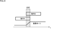
- control information R(t) of the superimposed motion R in which motion A and motion B are superimposed at time t is calculated by the following formula (2).
- r(t) is a function that indicates the overlap rate.
- the overlap rate r(t) may be linear or nonlinear with respect to time t, and may be optimized using machine learning.
- the inverse kinematics analysis unit 170 calculates the target value of the joint angle of each joint of the autonomous mobile body 11 based on the stabilization superimposition motion information.
- the inverse kinematics analysis unit 170 generates information indicating the target value of the joint angle of each joint (joint angle planning information) and supplies it to the servo control unit 114.
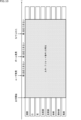
- FIG. 10 shows an example of an autonomous mobile object 11 performing a hand movement using a conventional control method.
- FIG. 10 shows the time-series control of the head 21, mouth, ears, right front leg (leg 23fr), left front leg (leg 23fl), hind legs (legs 23hr and 23hl), torso 22, and tail 24 of the autonomous mobile body 11.
- the joint of the head 21 of the autonomous mobile body 11 is driven by actuator 71A and actuator 71B in FIG. 2.
- the joint of the right front leg of the autonomous mobile body 11 is driven by actuator 71Efr, actuator 71Ffr, and actuator 71Gfr.
- the joint of the left front leg of the autonomous mobile body 11 is driven by actuator 71Efl, actuator 71Ffl, and actuator 71Gfl.
- the joint of the rear leg of the autonomous mobile body 11 is driven by actuator 71Ehr, actuator 71Fhr, actuator 71Ghr, actuator 71Ehl, actuator 71Fhl, and actuator 71Ghl.
- the joint of the torso 22 of the autonomous mobile body 11 is driven by actuator 71C etc.
- the joint of the tail 24 of the autonomous mobile body 11 is driven by actuator 71D.
- FIGS. 11 and 12 show an example in which the autonomous mobile object 11 performs a hand movement using the control method of the present technology.
- a base hand movement is performed only by the right front leg.
- the right leg performs manipulation according to the position of the user's hand.
- a preset movement may be played by the right leg.
- the trajectory, speed, etc. of the base movement may be adjusted based on self parameters.
- parts of the body other than the right leg, which is performing the base movement can essentially be freely assigned to non-base movements (additional movements, breathing movements, basic posture movements).
- the head 21 reproduces an emotional action in parallel with a base action.
- This emotional action is executed based on the emotion of the self parameters.
- This emotional action may be executed as a base action or as a non-base action.
- the head 12 follows the user while the reaction motion is played in parallel with the base motion.
- the interest of the autonomous mobile body 11 shifts from the user to the ball, and the head 12 follows the ball while the reaction motion is played.
- the head 12 plays the reaction motion in parallel with the base motion.
- left front leg, rear leg, and torso 22 perform balance control in response to external forces and gravity, swaying movements in response to breathing, and posture control that changes the basic posture in the time direction in parallel with the base movements.
- the tail 24 performs a swinging motion (a motion of wagging the tail 24) that matches the emotion of the self parameters at that time.
- This swinging motion of the tail 24 may be performed as a base motion or a non-base motion.
- the autonomous mobile body 11 can execute an action that expresses at least one of the emotions and states of the autonomous mobile body 11 in response to at least one of the surrounding circumstances and the state of the autonomous mobile body 11 in real time.
- this technology can be applied to pet-type robots other than the dog-type robot described above.
- this technology can be applied not only to pet robots, but also to any autonomous mobile object that can act autonomously and express emotions and states.
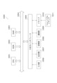
- FIG. 13 is a block diagram showing an example of the hardware configuration of a computer that executes the above-mentioned series of processes using a program.
- a CPU Central Processing Unit
- ROM Read Only Memory
- RAM Random Access Memory
- an input/output interface 1005 Connected to the input/output interface 1005 are an input unit 1006, an output unit 1007, a storage unit 1008, a communication unit 1009, and a drive 1010.
- the input unit 1006 includes an input switch, a button, a microphone, an image sensor, etc.
- the output unit 1007 includes a display, a speaker, etc.
- the storage unit 1008 includes a hard disk, a non-volatile memory, etc.
- the communication unit 1009 includes a network interface, etc.
- the drive 1010 drives removable media 1011 such as a magnetic disk, an optical disk, a magneto-optical disk, or a semiconductor memory.
- the CPU 1001 loads a program recorded in the storage unit 1008, for example, into the RAM 1003 via the input/output interface 1005 and the bus 1004, and executes the program, thereby performing the above-mentioned series of processes.
- the program executed by the computer 1000 can be provided by being recorded on a removable medium 1011 such as a package medium, for example.
- the program can also be provided via a wired or wireless transmission medium such as a local area network, the Internet, or digital satellite broadcasting.
- the program can be installed in the storage unit 1008 via the input/output interface 1005 by inserting the removable medium 1011 into the drive 1010.
- the program can also be received by the communication unit 1009 via a wired or wireless transmission medium and installed in the storage unit 1008.
- the program can be pre-installed in the ROM 1002 or storage unit 1008.
- the program executed by the computer may be a program in which processing is performed chronologically in the order described in this specification, or a program in which processing is performed in parallel or at the required timing, such as when called.
- a system refers to a collection of multiple components (devices, modules (parts), etc.), regardless of whether all the components are in the same housing. Therefore, multiple devices housed in separate housings and connected via a network, and a single device in which multiple modules are housed in a single housing, are both systems.
- this technology can be configured as cloud computing, in which a single function is shared and processed collaboratively by multiple devices over a network.
- each step described in the above flowchart can be executed by a single device, or can be shared and executed by multiple devices.
- one step includes multiple processes
- the multiple processes included in that one step can be executed by one device, or can be shared and executed by multiple devices.
- a motion planning unit that creates a motion plan; and a motion control unit that, while executing a base motion, which is a motion based on the motion plan, executes a superimposed motion, which is a motion in which an expression corresponding to at least one of a surrounding situation and the autonomous vehicle's own state is superimposed on the base motion.
- a superimposed motion which is a motion in which an expression corresponding to at least one of a surrounding situation and the autonomous vehicle's own state is superimposed on the base motion.
- the operation control unit selects the non-base action to be executed from among a plurality of candidate non-base actions in accordance with a priority.
- the non-base action is an action that is dynamically executed in response to at least one of the surrounding situation and the autonomous moving body's own state during execution of the base action.
- the non-base motion includes at least one of a motion added to express at least one of one's own emotions and states, a motion expressing breathing, and a motion expressing a basic posture in the base motion.
- the base action and the non-base action are realized by preset actions that are set in advance, or generated actions that are dynamically generated in response to at least one of the surrounding situation and the autonomous mobile body's own state.
- the motion control unit executes a posture stabilization process for the superimposed motion.
- the expression represents at least one of an emotion and a state of the autonomous moving body.
- the method includes, during execution of a base action, which is an action based on the action plan, having the autonomous moving body execute a superimposed action, which is an action in which an expression corresponding to at least one of a situation around the autonomous moving body and a state of the autonomous moving body is superimposed on the base action.
Landscapes
- Engineering & Computer Science (AREA)
- Robotics (AREA)
- Mechanical Engineering (AREA)
- Manipulator (AREA)
Priority Applications (1)
| Application Number | Priority Date | Filing Date | Title |
|---|---|---|---|
| JP2025510110A JPWO2024203004A1 (https=) | 2023-03-29 | 2024-03-05 |
Applications Claiming Priority (2)
| Application Number | Priority Date | Filing Date | Title |
|---|---|---|---|
| JP2023-053334 | 2023-03-29 | ||
| JP2023053334 | 2023-03-29 |
Publications (1)
| Publication Number | Publication Date |
|---|---|
| WO2024203004A1 true WO2024203004A1 (ja) | 2024-10-03 |
Family
ID=92904344
Family Applications (1)
| Application Number | Title | Priority Date | Filing Date |
|---|---|---|---|
| PCT/JP2024/008175 Ceased WO2024203004A1 (ja) | 2023-03-29 | 2024-03-05 | 自律移動体及び動作制御方法 |
Country Status (2)
| Country | Link |
|---|---|
| JP (1) | JPWO2024203004A1 (https=) |
| WO (1) | WO2024203004A1 (https=) |
Citations (7)
| Publication number | Priority date | Publication date | Assignee | Title |
|---|---|---|---|---|
| JP2011224756A (ja) * | 2010-04-22 | 2011-11-10 | Honda Motor Co Ltd | 2足移動ロボットの制御装置 |
| WO2012005779A1 (en) * | 2010-01-29 | 2012-01-12 | Irobot Corporation | Robotic vehicle |
| JP2016150419A (ja) * | 2015-02-18 | 2016-08-22 | トヨタ自動車株式会社 | ロボット制御装置、制御方法、及び制御プログラム |
| WO2019087484A1 (ja) * | 2017-10-30 | 2019-05-09 | ソニー株式会社 | 情報処理装置、情報処理方法、およびプログラム |
| WO2021117441A1 (ja) * | 2019-12-10 | 2021-06-17 | ソニーグループ株式会社 | 情報処理装置、その制御方法及びプログラム |
| JP2021194755A (ja) * | 2020-06-17 | 2021-12-27 | ソニーグループ株式会社 | 移動体および移動体の制御方法 |
| JP2022142109A (ja) * | 2021-03-16 | 2022-09-30 | カシオ計算機株式会社 | 電子機器、ロボット、制御方法及びプログラム |
-
2024
- 2024-03-05 JP JP2025510110A patent/JPWO2024203004A1/ja active Pending
- 2024-03-05 WO PCT/JP2024/008175 patent/WO2024203004A1/ja not_active Ceased
Patent Citations (7)
| Publication number | Priority date | Publication date | Assignee | Title |
|---|---|---|---|---|
| WO2012005779A1 (en) * | 2010-01-29 | 2012-01-12 | Irobot Corporation | Robotic vehicle |
| JP2011224756A (ja) * | 2010-04-22 | 2011-11-10 | Honda Motor Co Ltd | 2足移動ロボットの制御装置 |
| JP2016150419A (ja) * | 2015-02-18 | 2016-08-22 | トヨタ自動車株式会社 | ロボット制御装置、制御方法、及び制御プログラム |
| WO2019087484A1 (ja) * | 2017-10-30 | 2019-05-09 | ソニー株式会社 | 情報処理装置、情報処理方法、およびプログラム |
| WO2021117441A1 (ja) * | 2019-12-10 | 2021-06-17 | ソニーグループ株式会社 | 情報処理装置、その制御方法及びプログラム |
| JP2021194755A (ja) * | 2020-06-17 | 2021-12-27 | ソニーグループ株式会社 | 移動体および移動体の制御方法 |
| JP2022142109A (ja) * | 2021-03-16 | 2022-09-30 | カシオ計算機株式会社 | 電子機器、ロボット、制御方法及びプログラム |
Also Published As
| Publication number | Publication date |
|---|---|
| JPWO2024203004A1 (https=) | 2024-10-03 |
Similar Documents
| Publication | Publication Date | Title |
|---|---|---|
| JP7400923B2 (ja) | 情報処理装置および情報処理方法 | |
| JP3714268B2 (ja) | ロボット装置 | |
| JP7747032B2 (ja) | 情報処理装置及び情報処理方法 | |
| JP4239635B2 (ja) | ロボット装置、その動作制御方法、及びプログラム | |
| JP7238796B2 (ja) | 動物型の自律移動体、動物型の自律移動体の動作方法、およびプログラム | |
| Zuher et al. | Recognition of human motions for imitation and control of a humanoid robot | |
| JP7559900B2 (ja) | 情報処理装置、情報処理方法、およびプログラム | |
| JP7309371B2 (ja) | ロボット制御システム | |
| US12236152B2 (en) | Information processing apparatus and information processing method for displaying a feeling parameter associated with an autonomous moving body | |
| US20240066420A1 (en) | Autonomous moving object and information processing method | |
| JP7156300B2 (ja) | 情報処理装置、情報処理方法、およびプログラム | |
| JP4281286B2 (ja) | ロボット装置及びその制御方法 | |
| JP2004130427A (ja) | ロボット装置及びロボット装置の動作制御方法 | |
| WO2024203004A1 (ja) | 自律移動体及び動作制御方法 | |
| US20240367065A1 (en) | Autonomous mobile body, information processing method, and program | |
| US12564794B2 (en) | Autonomous mobile body and information processing method | |
| JP2003266364A (ja) | ロボット装置 | |
| JP2003266350A (ja) | ロボット装置及び内部状態表出装置 | |
| WO2020153298A1 (ja) | 画像解析システム | |
| WO2026018673A1 (ja) | 情報処理装置及び情報処理方法 | |
| JP2003266361A (ja) | 動力伝達装置及びロボット装置 | |
| JP2004299006A (ja) | ロボット装置及びロボット装置による顔認識状況の提示方法 | |
| WO2025037529A1 (ja) | 制御装置及び制御方法 | |
| JP2004298976A (ja) | ロボット装置及びロボット装置の認識制御方法 | |
| JP2005007501A (ja) | ロボット装置及びその動作制御方法 |
Legal Events
| Date | Code | Title | Description |
|---|---|---|---|
| 121 | Ep: the epo has been informed by wipo that ep was designated in this application |
Ref document number: 24779142 Country of ref document: EP Kind code of ref document: A1 |
|
| ENP | Entry into the national phase |
Ref document number: 2025510110 Country of ref document: JP Kind code of ref document: A |
|
| WWE | Wipo information: entry into national phase |
Ref document number: 2025510110 Country of ref document: JP |
|
| NENP | Non-entry into the national phase |
Ref country code: DE |
|
| 122 | Ep: pct application non-entry in european phase |
Ref document number: 24779142 Country of ref document: EP Kind code of ref document: A1 |