WO2024202744A1 - レーザ加工における被加工物の検査方法及び検査装置 - Google Patents
レーザ加工における被加工物の検査方法及び検査装置 Download PDFInfo
- Publication number
- WO2024202744A1 WO2024202744A1 PCT/JP2024/006388 JP2024006388W WO2024202744A1 WO 2024202744 A1 WO2024202744 A1 WO 2024202744A1 JP 2024006388 W JP2024006388 W JP 2024006388W WO 2024202744 A1 WO2024202744 A1 WO 2024202744A1
- Authority
- WO
- WIPO (PCT)
- Prior art keywords
- surface roughness
- workpiece
- signal
- training data
- calculated
- Prior art date
- Legal status (The legal status is an assumption and is not a legal conclusion. Google has not performed a legal analysis and makes no representation as to the accuracy of the status listed.)
- Ceased
Links
Images


Classifications
-
- B—PERFORMING OPERATIONS; TRANSPORTING
- B23—MACHINE TOOLS; METAL-WORKING NOT OTHERWISE PROVIDED FOR
- B23K—SOLDERING OR UNSOLDERING; WELDING; CLADDING OR PLATING BY SOLDERING OR WELDING; CUTTING BY APPLYING HEAT LOCALLY, e.g. FLAME CUTTING; WORKING BY LASER BEAM
- B23K26/00—Working by laser beam, e.g. welding, cutting or boring
- B23K26/02—Positioning or observing the workpiece, e.g. with respect to the point of impact; Aligning, aiming or focusing the laser beam
- B23K26/04—Automatically aligning, aiming or focusing the laser beam, e.g. using the back-scattered light
-
- B—PERFORMING OPERATIONS; TRANSPORTING
- B23—MACHINE TOOLS; METAL-WORKING NOT OTHERWISE PROVIDED FOR
- B23K—SOLDERING OR UNSOLDERING; WELDING; CLADDING OR PLATING BY SOLDERING OR WELDING; CUTTING BY APPLYING HEAT LOCALLY, e.g. FLAME CUTTING; WORKING BY LASER BEAM
- B23K26/00—Working by laser beam, e.g. welding, cutting or boring
- B23K26/02—Positioning or observing the workpiece, e.g. with respect to the point of impact; Aligning, aiming or focusing the laser beam
- B23K26/03—Observing, e.g. monitoring, the workpiece
- B23K26/032—Observing, e.g. monitoring, the workpiece using optical means
-
- G—PHYSICS
- G01—MEASURING; TESTING
- G01B—MEASURING LENGTH, THICKNESS OR SIMILAR LINEAR DIMENSIONS; MEASURING ANGLES; MEASURING AREAS; MEASURING IRREGULARITIES OF SURFACES OR CONTOURS
- G01B11/00—Measuring arrangements characterised by the use of optical techniques
- G01B11/30—Measuring arrangements characterised by the use of optical techniques for measuring roughness or irregularity of surfaces
- G01B11/303—Measuring arrangements characterised by the use of optical techniques for measuring roughness or irregularity of surfaces using photoelectric detection means
Definitions
- This disclosure relates to a method and device for inspecting workpieces in laser processing.
- Patent Document 1 discloses a method for determining the welding condition of a workpiece, such as good/bad, applied to laser welding, in which a pulsed laser beam is irradiated onto the workpiece to perform welding.
- the method of Patent Document 1 detects the intensity of plasma light and reflected light emitted from the workpiece during laser welding, and extracts a pulse-by-pulse feature value for each pulse of the laser beam based on the detected light intensity in a preset extraction section of one cycle corresponding to one pulse of the laser beam.
- the pulse-by-pulse feature value the average value of the detected light intensity, the amount of change due to differential processing, the amplitude due to differential processing, etc. are calculated.
- the method of Patent Document 1 compares the lower limit or upper limit of the pulse-by-pulse feature value with a predetermined threshold value, and determines the occurrence of a welding defect as the welding condition for each workpiece.
- the condition of the workpiece can affect the processing accuracy and the quality after processing.
- differences in the surface roughness of the workpiece can affect the welding quality, and identifying the cause of such an effect takes time as it requires detailed understanding, including causes other than surface roughness, such as cross-sectional observation of the processed part.
- measuring the surface roughness after each processing increases production time loss, and furthermore, measuring surface roughness requires a high-precision measuring instrument, so it is not realistic to inspect the workpiece by measuring the surface roughness before each processing in production facilities.
- This disclosure provides an inspection device and inspection method that can make it easier to inspect the surface roughness of a workpiece during laser processing.
- a method for inspecting a workpiece during laser processing is provided.
- the inspection method is as follows: A step of detecting at least one component of thermal radiation, visible light, and reflected light generated by irradiating a workpiece with a laser beam using an optical sensor, and acquiring a signal indicating a change in the component during a time period corresponding to a processing time for each workpiece; calculating a feature quantity indicative of a feature of a signal in a predetermined section of the time section; A step of inputting the calculated feature amount into a surface roughness judgment model that indicates the surface properties of the surface of the workpiece irradiated with the laser light, and judging the surface roughness of the workpiece; and outputting the calculated predicted value of surface roughness as an inspection result.
- the judgment model is constructed based on training data that contains correlations between feature values calculated from component signals detected by performing laser processing under multiple conditions in which the surface roughness is varied and the surface roughness for each condition.
- an inspection device for a workpiece in laser processing includes an arithmetic circuit and a communication circuit that receives a signal generated by detecting at least one of the components of thermal radiation, visible light, and reflected light generated by irradiating a workpiece with a laser beam using an optical sensor.
- the signal is a signal indicating a change in the component in a time section corresponding to the processing time for each workpiece.
- the arithmetic circuit acquires the signal using the communication circuit, calculates a feature value indicating the characteristics of the signal in a predetermined section of the time section, inputs the calculated feature value into a judgment model that judges the surface roughness indicating the surface properties of the surface of the workpiece irradiated with the laser beam, judges the surface roughness of the workpiece, and outputs the calculated predicted value of the surface roughness as the inspection result.
- the judgment model is constructed based on training data that includes an association between the feature value calculated from the signal of the component detected by performing laser processing under each of a plurality of conditions in which the surface roughness is varied and the surface roughness under each condition.
- the inspection method and inspection device disclosed herein make it easier to inspect the surface roughness of a workpiece during laser processing.
- FIG. 1 is a diagram showing an overview of an inspection system according to a first embodiment of the present disclosure.
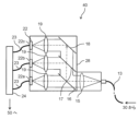
- FIG. 1 is a diagram illustrating a configuration example of a laser processing device in an inspection system.
- FIG. 1 is a diagram illustrating a configuration of a spectroscopic device in an inspection system;
- FIG. 1 is a block diagram illustrating a configuration of an inspection device in an inspection system;
- 1 is a flowchart illustrating an example of an inspection process in an inspection device;
- FIG. 1 is a diagram for explaining a signal acquired by an inspection device;
- FIG. 1 is a diagram for explaining the relationship between feature amounts calculated by an inspection device and surface roughness.
- a flowchart illustrating a training process for a determination model used in an inspection process.
- a diagram for explaining training data for a decision model 1 is a flowchart illustrating a process for generating training data;
- Embodiment 1 As an example of using the inspection method and inspection device according to the present disclosure, an inspection system is described that detects components of light generated during laser processing for lap welding, obtains a signal based on the detected components, and inspects the surface roughness of a workpiece.
- Fig. 1 is a diagram showing an overview of an inspection system 100 according to the present embodiment.
- the inspection system 100 includes a laser processing device 30 that performs laser processing for overlap welding, a spectrometer 40 that detects light components, and an inspection device 50.
- the workpiece 70 for laser processing is made of, for example, metal, and when the laser light 6 is irradiated, thermal radiation in the near infrared region due to temperature rise and metal-specific light emission or plasma light emission (hereinafter referred to as "visible light"), which is mainly a visible light component, are generated. In addition, a part of the laser light 6 that does not contribute to processing is reflected as return light. In this way, when the laser light 6 is irradiated from the laser processing device 30 to the workpiece 70, thermal radiation, visible light, and reflected light are generated, for example, in the molten part 27 formed by melting the metal on the workpiece 70.
- These generated lights are collected in the laser processing device 30 and transmitted to the spectroscopic device 40 through the optical fiber 13 connecting the laser processing device 30 and the spectroscopic device 40.
- the light transmitted to the spectroscopic device 40 is split into thermal radiation, visible light, and reflected light components, which are detected by the optical sensor 22 of the spectroscopic device 40 and converted into signals.
- the inspection device 50 receives a signal from the spectroscopic device 40, it determines the surface roughness of the workpiece 70 based on the received signal, and outputs the determined surface roughness as the inspection result of the workpiece 70.
- the laser processing device 30 includes a laser oscillator 1, a laser transmission fiber 2, a lens barrel 3, a collimator lens 4, focusing lenses 5 and 11, a first mirror 7, and a second mirror 8.
- the laser oscillator 1 supplies light to generate pulsed laser light 6, for example, with a wavelength of approximately 1070 nanometers (nm).
- the light supplied from the laser oscillator 1 is amplified while being transmitted through the laser transmission fiber 2, passes through a collimating lens 4 to obtain a parallel beam, forms the laser light 6, and travels straight through the lens barrel 3.
- the lens barrel 3 constitutes the processing head of the laser processing device 30.
- the laser light 6 is reflected by the first mirror 7 except for a portion that passes through, then focused by the focusing lens 5 and irradiated onto the workpiece 70 fixed, for example, by a pressing jig 26 on a scanning table. This performs laser processing for overlap welding of the workpiece 70.
- the wavelength of the laser light 6 is not limited to 1070 nm, and it is preferable to use a wavelength that is highly absorbed by the material.
- the molten part 27 When the laser light 6 is irradiated, the molten part 27 generates thermal radiation from the workpiece 70, visible light due to plasma emission, and reflected light of the laser light 6. These light components pass through the first mirror 7, are reflected by the second mirror 8, and are collected by the collecting lens 11, and then transmitted to the spectrometer 40 through the optical fiber 13.
- the laser processing device 30 of this embodiment further includes an optical sensor 25, which detects the light that is partially transmitted by the second mirror 8.
- the optical sensor 25 generates an electrical signal according to the intensity of the detected light.
- the generated electrical signal may be transmitted to the controller 24 of the spectrometer 40, which will be described later, via, for example, a transmission cable connecting the laser processing device 30 and the spectrometer 40.
- the detection position of the transmitted light by the optical sensor 25 can be detected, for example, at a position before the laser light 6 reaches the workpiece 70, so that the correlation between the signal strength of the detection result and the output of the laser oscillator 1 can be obtained with high accuracy, but the detection position is not particularly limited to this.
- Fig. 3 is a diagram illustrating the configuration of a spectroscopic device 40 of this embodiment.
- the spectroscopic device 40 includes a collimator lens 15, a third mirror 16, a fourth mirror 17, a fifth mirror 18, condenser lenses 19, 20, and 21, a light sensor 22, a transmission cable 23, and a controller 24 inside a housing 28.
- the housing 28 prevents unwanted light from entering the inside of the spectroscopic device 40 from the outside, and prevents light leakage from the inside.
- the collimating lens 15 returns the light transmitted from the laser processing device 30 through the optical fiber 13 to parallel light.
- the third mirror 16 transmits visible light with a wavelength of, for example, 400 nm to 700 nm, and reflects other components.
- the fourth mirror 17 reflects the reflected light of the laser light 6 with a wavelength of, for example, approximately 1070 nm, and transmits other components.
- the fifth mirror 18 reflects thermal radiation with a wavelength of, for example, 1300 nm to 1550 nm.
- the light that passes through the collimating lens 15 is split into visible light, reflected light, and thermal radiation components by the third mirror 16, fourth mirror 17, and fifth mirror 18, and each of these components is focused by focusing lenses 19 to 21. Note that by placing any bandpass filter in the optical path after the third mirror 16, fourth mirror 17, and fifth mirror 18, it may be possible to select the wavelengths to pass through.
- the optical sensor 22 includes, for example, optical sensors 22a, 22b, and 22c, each of which has high sensitivity to different wavelengths.
- the optical sensors 22a, 22b, and 22c detect the visible light, reflected light, and thermal radiation components collected by the respective collecting lenses 19 to 21, and generate an electrical signal according to the intensity of the detected light.
- the optical sensor 22 may be configured as a single optical sensor capable of detecting the intensity for each wavelength.
- the electrical signal generated by the optical sensor 22 is transmitted to the controller 24 via the transmission cable 23.
- the controller 24 is a hardware controller and controls the overall operation of the spectrometer 40.
- the controller 24 includes a CPU, a communication circuit, etc., and transmits the electrical signal received from the optical sensor 22 to the inspection device 50.
- the controller 24 is equipped with, for example, an A/D converter, and converts the analog electrical signal into a digital signal (also simply called a "signal").
- the sampling period for converting into a digital signal is preferably, for example, 1/100 or less of the time for output control of the laser light 6, from the viewpoint of ensuring a sufficient number of samples to capture the characteristics of the processing process and the trends in local values of physical quantities.
- FIG. 4 is a block diagram illustrating the configuration of an inspection apparatus 50 according to this embodiment.
- the inspection apparatus 50 is configured with an information processing apparatus such as a computer.
- the inspection apparatus 50 includes a CPU 51 that performs calculation processing, a communication circuit 52 for communicating with other devices, and a storage device 53 that stores data and computer programs.
- the CPU 51 is an example of an arithmetic circuit of the inspection device 50 in this embodiment.
- the CPU 51 executes a control program 56 stored in the storage device 53 to realize predetermined functions including constructing a judgment model 57 and inspecting the workpiece 70 using the constructed judgment model 57.
- the CPU 51 executes the control program 56 to realize the functions of the inspection device 50 in this embodiment.
- the arithmetic circuit of the inspection device 50 configured as the CPU 51 may be realized by various processors such as an MPU or GPU, or may be configured by one or more processors.
- the communication circuit 52 is a communication circuit that communicates in accordance with a standard such as IEEE 802.11, 4G, or 5G.
- the communication circuit 52 may perform wired communication in accordance with a standard such as Ethernet (registered trademark).
- the communication circuit 52 is connectable to a communication network such as the Internet.
- the inspection device 50 may also directly communicate with other devices via the communication circuit 52, or may communicate via an access point.
- the communication circuit 52 may be configured to be able to communicate with other devices without going through a communication network.
- the communication circuit 52 may include connection terminals such as a USB (registered trademark) terminal and an HDMI (registered trademark) terminal.
- the storage device 53 is a storage medium that stores computer programs and data necessary to realize the functions of the inspection system 100.
- the storage device 53 stores the control program 56 executed by the CPU 51 and various data, and stores the judgment model 57 after it is constructed.
- the judgment model 57 is constructed by machine learning based on training data that includes, for multiple processing conditions under which the surface roughness of the workpiece 70 differs, feature quantities that indicate the characteristics of the signal detected during laser processing under each condition associated with the surface roughness obtained by measurement under each condition.
- the judgment model 57 is a regression model realized by, for example, linear regression, lasso regression, ridge regression, decision tree, random forest, gradient boosting, support vector regression, Gaussian process regression, k-nearest neighbor method, or neural network.
- the judgment model 57 in this embodiment outputs a numerical value indicating the vertical displacement of the workpiece 70 from a reference surface as a result of the surface roughness judgment. The construction of the judgment model 57 will be described in detail later.
- the storage device 53 is, for example, a magnetic storage device such as a hard disk drive (HDD), an optical storage device such as an optical disk drive, or a semiconductor storage device such as a solid-state drive (SSD).
- the storage device 53 may also include a temporary storage element such as a RAM such as a DRAM or an SRAM, and may function as an internal memory of the CPU 51.
- the spectroscopic device 40 detects the components of thermal radiation, visible light, and reflected light generated in the molten part 27 by irradiation with the laser light 6, using the optical sensor 22.
- the spectroscopic device 40 transmits a signal according to the intensity of each detected component to the inspection device 50.
- the operation of the inspection device 50 in this system 100 will be described below.
- FIG. 5 is a flowchart illustrating the determination process in the inspection device 50 of this embodiment. Each process shown in this flowchart is executed, for example, by the CPU 51 of the inspection device 50. This flowchart is started, for example, when a user of the inspection system 100 inputs a predetermined operation to start the inspection process from an input device connected via the communication circuit 52.
- the CPU 51 acquires signals corresponding to the components of thermal radiation, visible light, and reflected light detected by the optical sensor 22 of the spectrometer 40 via the communication circuit 52 (S1).
- FIG. 6 is a diagram for explaining signals acquired by the inspection device 50.
- FIGS. 6(A), (B), and (C) show signal waveforms corresponding to the intensities of thermal radiation, visible light, and reflected light, respectively.
- FIG. 6(D) shows the output of the laser light 6 irradiated to the workpiece 70.
- the signals in FIGS. 6(A) to (C) correspond to the thermal radiation, visible light, and reflected light generated by the laser output.
- the horizontal axis indicates time
- the vertical axis indicates the signal intensity (FIGS. 6(A) to (C)) or the laser output (FIG. 6(D)).
- the time interval T1 indicates the time interval corresponding to one pulse of the laser light 6
- the time interval T2 indicates the time interval of the peak output excluding the rising and falling edges of the laser output.
- the laser processing device 30 performs welding for each workpiece 70 in a time interval T1 corresponding to one pulse of the laser light 6.
- the CPU 51 acquires signals indicating changes in the components of thermal radiation, visible light, and reflected light in the time interval T1 corresponding to the welding time for each workpiece 70, as shown in FIGS. 6(A) to 6(C).
- the CPU 51 calculates feature quantities to be input to the judgment model 57 from the acquired signal (S2).
- the feature quantities are calculated, for example, from a signal waveform showing the time change in the signal strength of each component, and include an average intensity showing the average value of the signal strength in the time interval T2, and an integrated value of the signal strength in the time interval T2.
- the CPU 51 inputs the feature values calculated from the signals of each component detected during processing of the workpiece 70 into the judgment model 57, and performs judgment model processing (S3) to judge the surface roughness of the workpiece 70.
- the CPU 51 calculates a predicted value of a numerical value indicating the surface roughness of the upper surface of the workpiece 70 irradiated with the laser light 6. The relationship between these feature values and surface roughness will be described in detail later.
- the CPU 51 outputs the numerical value of the surface roughness of the top surface of the workpiece 70 calculated by processing the judgment model (S3) as the inspection result of the workpiece 70 (S4).
- the CPU 51 may write out the inspection result to the storage device 53, for example, or may transmit the inspection result to the outside of the inspection device 50 via the communication circuit 52.
- the inspection result may be received and displayed, for example, by an information processing device or display device external to the inspection device 50.
- the inspection device 50 may be provided with a display device (e.g., a display) capable of communicating with the CPU 51, and the inspection result may be displayed on the display device.
- the CPU 51 ends the flowchart in FIG. 5.
- the flowchart in FIG. 5 is executed repeatedly, for example, each time welding is performed on each workpiece 70.
- the inspection device 50 of this embodiment acquires the signal generated by the optical sensor 22 of the spectrometer 40 (S1), calculates features from the signal (S2), and processes the judgment model 57 to inspect the surface roughness of the workpiece 70 based on the features (S3).
- the surface roughness of the top surface of the workpiece 70 which is the irradiated surface of the laser light 6, can be inspected from the light signal generated during laser processing without directly measuring it. This makes it easier to inspect the surface roughness, and makes it possible to grasp, for example, the effect on the processing state due to variations in surface roughness for each processing step.
- the inspection device 50 described above when used at a manufacturing site for products produced by laser processing, by setting criteria for determining whether or not poor welding will occur in relation to surface roughness, it is possible to reject poorly welded products according to the inspection results, for example, so that poorly welded products do not flow into subsequent processes.
- Figure 7 is a diagram for explaining the relationship between the feature values calculated by the inspection device 50 and the surface roughness.
- Figure 7(A) shows the change over time in the signal intensity of the reflected light detected during processing for each case where the workpiece 70 has a different surface roughness.
- Figure 7(B) shows the change over time in the signal intensity of the thermal radiation or visible light detected for each case similar to that of Figure 7(A).
- Figure 7(C) shows a schematic diagram of the relationship between the surface roughness of the workpiece 70 and the molten zone 27 formed during processing.
- the surface reflection of the laser light 6 on the workpiece 70 and/or the flow of the molten metal in the molten zone 27 changes, affecting the shape of the molten zone 27.
- the shape of the molten zone 27 changes, and the detected signal intensity changes as shown in FIGS. 7(A) and (B) in response to the change in the amount of light emitted and scattered in the molten zone 27.
- the molten metal produced by the laser light 6 is less likely to spread in the molten width direction, i.e., in the direction perpendicular to the scanning direction, and the input heat can be concentrated while maintaining its shape. This causes the melting temperature to rise, and the surface temperature of the molten area 27 becomes higher, so it is assumed that the amount of light emitted and the corresponding signal strength are relatively large.
- the surface roughness is large, then the molten metal in the molten area 27 is more likely to spread in the molten width direction, and the amount of heat can be dispersed. This causes the surface temperature of the molten area 27 to decrease, and it is assumed that the amount of light emitted and the corresponding signal strength are relatively small.
- a judgment model 57 is constructed by a training process described below, which judges the surface roughness of the workpiece 70 using a feature value corresponding to the signal strength from a signal corresponding to at least one component of thermal radiation, visible light, and reflected light during processing.
- the feature values input to such a judgment model 57 are described below.
- the CPU 51 of the inspection device 50 calculates the average intensity of each signal as a feature value in a time interval T2 corresponding to the period of peak output for each processing by the laser oscillator 1 of the laser processing device 30.
- the time interval T2 can be determined, for example, from the output waveform of the laser oscillator 1.
- the CPU 51 calculates, as a feature value corresponding to such changes in the amount of light, for example, the integrated value of the signal intensity during the time period T2 when the laser light 6 is at its peak output.
- FIG. 8 is a flowchart illustrating an example of a training process for a judgment model 57 used in the inspection process. Each process in this flowchart is executed by, for example, the CPU 51 of the inspection device 50.
- the CPU 51 acquires training data that has been stored in advance, for example, in the storage device 53 (S11).
- FIG. 9 is a diagram for explaining the training data D1 of the judgment model 57.
- the training data D1 is data that associates the feature amount for each processing of the workpiece 70 with the actual measured value of the surface roughness of the workpiece 70 measured, for example, before the processing.
- the training data D1 is constructed by performing laser processing using the laser processing device 30 under a plurality of conditions in which the processing conditions during welding are changed, for example, and acquiring data such as signals detected via the spectrometer 40 and the actual measured value of the surface roughness.
- the training data D1 in FIG. 9 records the output of the laser oscillator 1 in association with each condition, in addition to the feature quantities of the average intensity and integral value calculated based on the signals of each component of thermal radiation, visible light, and reflected light.
- the actual measurement value of surface roughness for example, the arithmetic mean height Ra or maximum height Rz of the line roughness indicating the two-dimensional surface properties, or the arithmetic mean height Sa or maximum height Sz of the surface roughness indicating the three-dimensional surface properties, are calculated from the measurement results of the top surface of the workpiece 70 using a shape measuring instrument or the like.
- the surface roughness may include multiple of these indices.
- measurements and laser processing may be performed multiple times under each condition, and the average value of the multiple data obtained may be used as the actual measurement value and feature quantity for that condition.
- the surface roughness for example, the displacement in the height direction from a predetermined reference surface is changed by polishing the surface of the workpiece 70 with sandpaper of different grits.
- multiple surface roughness conditions may be set for each grit of sandpaper, but this is not limited to this.
- measurement results of the joint strength may be obtained after processing under each condition. The generation of the training data D1 will be described in detail later.
- the CPU 51 performs machine learning using the acquired training data D1 to generate a judgment model 57 to calculate the corresponding surface roughness from the feature amount (S12).
- the CPU 51 performs machine learning of the judgment model 57 to minimize the error between the surface roughness determined by the judgment model 57 from the feature amount for each condition in the training data D1 and the surface roughness in the training data D1 for each condition.
- a judgment model 57 can be generated as a trained model that calculates a predicted value of surface roughness from feature quantities calculated from the signals of the components of thermal radiation, visible light, and reflected light detected during laser processing.
- the training process for the judgment model 57 may be executed in an information processing device other than the inspection device 50.
- the inspection device 50 may acquire the constructed judgment model by the communication circuit 52, for example, via a communication network.
- the training data D1 is not limited to the example in FIG. 9, and may include, for example, feature amounts calculated for some components of thermal radiation, visible light, and reflected light, or may include only one of the average intensity and the integral value.
- the inspection device 50 of this embodiment performs a process of generating training data D1 for the judgment model 57, for example, before the above-mentioned process of generating the judgment model 57.
- This process includes, for example, pre-processing for generating the judgment model 57 with high accuracy based on the training data D1 obtained by this process.
- the process of generating the training data D1 will be described with reference to FIG.
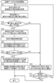
- FIG. 10 is a flowchart illustrating the process of generating training data D1.
- the process of this flowchart is started in a state where the surface roughness measurement results measured before processing and the signals of each component of reflected light etc. detected during laser processing are obtained under multiple conditions in which the surface roughness of a workpiece 70 similar to the inspection target is changed.
- the surface roughness measurement results and signals under each of these processing conditions are stored, for example, in the storage device 53 of the inspection device 50.
- the multiple processing conditions are, for example, set in advance and stored in the storage device 53.
- each process of this flowchart is executed, for example, by the CPU 51 of the inspection device 50.
- a predetermined pre-processing is performed on the surface roughness measurement results and the detected signals before the training data D1 is generated (S23, S25 to S27, etc.).
- signals during processing may vary not only due to changes in the surface roughness of the workpiece 70, but also due to foreign matter such as dirt adhering to the surface. If the training data D1 contains a large number of such signals that vary due to factors other than surface roughness, there is a concern that the judgment model 57 trained with the training data D1 will have difficulty learning the correlation between the signal features and surface roughness.
- the pre-processing in this embodiment includes processing to suppress such signals from being included in the training data D1.
- the CPU 51 acquires the surface roughness measurement results measured by a shape measuring device or the like under one processing condition, for example from the storage device 53 (S21).
- the accuracy of the measuring device is preferably capable of measuring to the order of nanometers (nm), but there is no particular restriction as long as it is of the order of micrometers ( ⁇ m).
- the area to be measured on the surface of the workpiece 70 may be determined according to the welding shape, for example, the area according to the range irradiated with the laser light 6. Workpieces 70 with different surface roughness may be created, for example, by changing the grit of the sandpaper used to polish the surface of the workpiece 70 before processing in increments of 100.
- the bond strength of the welded workpiece 70 may also be measured.
- the tensile strength may be measured using a tensile tester, or the torque strength may be measured, but the measurement method is not particularly limited.
- the measurement results of the bond strength can be managed in association with the training data D1, for example, as to whether or not the desired bond strength is ensured for each condition.
- the CPU 51 calculates the arithmetic mean height and maximum height from the surface roughness measurement results (S22). For example, the parameters of the arithmetic mean height Ra and maximum height Rz of the line roughness, or the arithmetic mean height Sa and maximum height Sz of the surface roughness are calculated depending on the measurement method.
- the surface roughness parameters Sa and Sz are parameters that are three-dimensional extensions of the line roughness parameters Ra and Rz calculated from the contour curve based on the measurement results. For example, the arithmetic mean heights Ra and Sa can be found by the following calculations.
- b is the reference length of the profile curve in measuring line roughness
- A is the reference area in measuring surface roughness
- Z is the coordinate value in the height direction based on the measurement results.
- the arithmetic mean height Sa and maximum height Sz of the surface roughness are calculated in step S22.
- the arithmetic mean height may also be simply referred to as the "average height.”
- the maximum height Sz is calculated as the sum of the maximum peak height and maximum valley depth in the reference area A.
- the CPU 51 determines whether the calculated maximum height Sz is equal to or less than the average height Sa multiplied by a predetermined value, i.e., whether the maximum height Sz and the average height Sa have the relationship "Sz ⁇ Sa ⁇ predetermined value" (S23).
- a predetermined value i.e., whether the maximum height Sz and the average height Sa have the relationship "Sz ⁇ Sa ⁇ predetermined value" (S23).
- the CPU 51 acquires a signal detected by the optical sensor 22 during processing for the processing conditions under which the measurement results used to calculate each parameter Sz and Sa were obtained (S24).
- the CPU 51 does not process step S24 and proceeds to step S30.
- the CPU 51 sets the processing conditions under which the parameters Sz and Sa were calculated as the target for remeasurement, or transitions the processing condition to be processed to the condition under which processing is performed next among the multiple processing conditions set in advance (S30).
- the CPU 51 determines, for example, whether there is a remeasurement or a next processing condition under multiple processing conditions (S31), and if there is a remeasurement or a next processing condition (YES in S31), returns to step S21.
- the CPU 51 obtains the measurement results of the remeasured surface roughness or the measurement results under the next processing condition (S21), and repeats the processing from step S22 onwards.
- signals are obtained under processing conditions under which the parameters Sz and Sa are calculated (S24) according to the relationship between the maximum height Sz and the average height Sa using predetermined values (S23), or remeasurements are performed (S30).
- S24 parameters Sz and Sa are calculated
- S23 predetermined values
- S30 remeasurements
- step S23 may be experimentally set, taking into consideration the fluctuation of each parameter Sz and Sa due to the above-mentioned disturbance factors.
- the calculation for determining the relationship between each parameter Sz and Sa is not limited to the example of step S23.
- step S30 may be executed to exclude the measurement result from the training data D1 when a foreign object or dirt on the surface is detected by image processing in an image of the surface of the workpiece 70 taken by a camera.
- the surface roughness may be measured in the vicinity of the molten part 27 after welding, or the surface roughness may be measured in the area to be welded under the same workpiece 70 and processing conditions as before the re-measurement, and then welding may be performed again and the subsequent processing may be executed.
- the surface roughness is considered to be roughly the same in the molten part 27 and its vicinity, and the measurement position of the surface roughness is not particularly limited as long as it is the surface of the workpiece 70 to which the laser light 6 is irradiated, but the area before welding where the molten part 27 is formed is more preferable.
- the CPU 51 may execute a process to correct the start time of the signal (S25), for example to unify the rising start times of the signal waveforms (i.e., start times) among the multiple signals acquired each time step S24 is executed.
- the start times of the signals shown in Figures 6 (A) to (C) may be set by the inspection device 50 to the time of receipt of a trigger signal output from the laser processing device 30 when the laser light 6 is oscillated. At this time, an error may occur in the start time due to an error in the start time of the trigger signal, etc.
- step S25 the CPU 51 performs a correction to offset the start time of the signal, for example, according to the time when the signal strength reaches a predetermined value (e.g., 0.2 V) at the rising edge of the signal waveform.
- a predetermined value e.g. 0. V
- the conditions at the time of calculation can be unified between signals, and training data D1 that can be used to construct the judgment model 57 with even greater accuracy can be obtained.
- the CPU 51 sets a time interval T2 corresponding to the peak power of the laser output as a predetermined time interval for the signal for each processing, for example, and calculates the percentage of the period during which the signal strength exceeds a predetermined threshold within the time interval T2 based on the acquired signal (S26).
- the predetermined threshold is set, for example, based on an average signal waveform, i.e., an average waveform, for each component of reflected light, thermal radiation, and visible light, and stored in the storage device 53.
- the average waveform is calculated as a waveform obtained by averaging the signal strength of the signal acquired each time by performing laser processing multiple times in advance for each processing condition, for example.
- the upper threshold value is set by adding the standard deviation of the signal strength to the average value of the signal strength in the time interval T2 of the average waveform
- the lower threshold value is set by subtracting the standard deviation from the average value of the signal strength.
- step S26 the CPU 51 calculates the percentage (also called the "NG percentage") at which the signal strength of the acquired signal exceeds the threshold of the average waveform as described above (i.e., is greater than the upper threshold or smaller than the lower threshold).
- the NG percentage may be calculated as a percentage by multiplying the value calculated using the following formula (1) by "100".
- the number of sampling points of the corresponding signals may be used as the time interval T2 and the period over the threshold.
- NG ratio period exceeding threshold within time interval T2/time interval T2 (1)
- the CPU 51 determines whether the calculated NG rate is less than a predetermined value (for example, 20%) (S27).
- the CPU 51 calculates a feature amount based on the acquired signal (S28). For example, as described above, the CPU 51 calculates the average value and integral value of the signal intensity in the time interval T2 as the feature amount. In step S28, other feature amounts may be calculated depending on the feature amount used in the inspection process (FIG. 5).
- the CPU 51 does not particularly calculate the feature amount (S28), and proceeds to step S30, just as in the case where the average surface roughness height Sa and the maximum height Sz do not have a predetermined relationship (NO in S23). For example, the CPU 51 sets the processing conditions under which the ratio was calculated as the target for remeasurement, or transitions the processing conditions to be processed to the next processing conditions (S30).
- the CPU 51 associates the feature amount calculated in step S28 with the calculated surface roughness value calculated from the measurement results under the processing conditions under which the feature amount was calculated, where the parameters Sa and Sz have the predetermined relationship in step S23, and adds them to the training data D1 (S29).
- the calculated surface roughness value may be either the average height Sa or the maximum height Sz, or both may be added.
- the CPU 51 stores or updates the added training data D1 in the storage device 53.
- the CPU 51 After adding the calculated values of the features and surface roughness to the training data D1 (S29), the CPU 51 proceeds to the judgment of step S31, and if there is a next processing condition among the multiple processing conditions (YES in S31), it repeats the processing from S21 onwards for the next processing condition.
- the calculated value calculated from the surface roughness measurement results (S21, S22) and the feature amount calculated from signals such as reflected light detected during processing (S24, S28) are associated with each other and added to the training data D1 (S29).
- the training data D1 generated by such a generation process can be used to perform the training process (FIG. 8) of the judgment model 57.
- pre-processing is performed on the acquired surface roughness and signals, excluding data that is likely to fluctuate due to disturbances, etc. (S23, S26-S27), and correcting the start times of the signals to be uniform (S25). This can improve the quality of the data included in the training data D1, for example.
- the threshold value of the average waveform in step S26 may be set based on the signal after the start time has been corrected using the same process as in step S25, or may be set based on the average value and standard deviation of the signal acquired in step S24. In addition, instead of the standard deviation, a value obtained by multiplying the standard deviation by a predetermined ratio may be used.
- the calculation period for the percentage exceeding the threshold value in step S26 is not limited to the time interval T2, and may be set, for example, by the user of the inspection device 50 via the communication circuit 52, etc.
- the predetermined value in step S27 is preferably changeable by the user, for example, but may be set automatically in the inspection device 50.
- the predetermined value may be set for the laser output, and is preferably set for each of the reflected light, thermal radiation, and visible light, but may also be set to a common value.
- the inspection process (S1 to S4) provides a method for inspecting the workpiece 70 in laser processing.
- This method includes a step (S1) of acquiring a signal that is generated by detecting at least one component of the heat radiation, visible light, and reflected light components generated by irradiating the workpiece 70 with the laser light 6 using the optical sensor 22 and indicates a change in the component in a time section T1 corresponding to the welding time for each workpiece 70, a step (S2) of calculating a feature amount that indicates a feature of the signal in a time section T2 (an example of a predetermined section) of the time section T1, a step (S3) of inputting the calculated feature amount into a judgment model 57 that judges the surface roughness that indicates the surface properties of the surface of the workpiece 70 irradiated with the laser light 6, and judging the surface roughness of the workpiece 70, and a step (S4) of outputting the judged surface roughness as an inspection result.
- the judgment model 57 that judges the surface roughness that indicates
- a signal is obtained by detecting one or more components of thermal radiation, visible light, and reflected light generated by irradiating the workpiece 70 with the laser light 6 (S1), and a feature value is calculated based on the signal (S2).
- a prediction value of the surface roughness is then calculated from the feature value by a judgment model 57 constructed based on the training data D1 (S3).
- the judgment model 57 for example, it is possible to inspect the surface roughness based on the predicted value without directly measuring the surface roughness, making it easier to inspect the surface roughness.
- the surface roughness of the training data D1 is measured in an area corresponding to the range where the laser light 6 is irradiated on the surface of the workpiece 70 (similar to the inspection target) under each condition.
- the surface roughness may be measured in the area where the molten part 27 is formed by welding on the surface of the upper material of the workpiece 70 on the side where the laser light 6 is irradiated.
- the time interval T2 corresponds to the period during which the laser light 6 is irradiated at peak power for each workpiece 70 (see FIG. 6), and the feature value includes the average intensity of the signal during the time interval T2.
- the signal intensity, particularly at peak power can change depending on the change in surface roughness. Therefore, it is believed that the surface roughness can be predicted with high accuracy by using the average intensity during the time interval T2 as the feature value.
- the feature quantity further includes an integral value of the signal over time interval T2.
- surface roughness can affect the shape of the molten part 27 formed during processing, and therefore the amount of heat input by irradiation with the laser light 6 can change, and the amount of light from the surface can increase or decrease along with fluctuations in the surface temperature of the molten part 27. It is believed that by using the integral value, such changes in the amount of light can be reflected in the feature quantity, making it possible to accurately predict the surface roughness.
- the surface roughness includes an arithmetic mean height Sa and a maximum height Sz calculated based on the vertical displacement from a reference surface (an example of a reference surface on the surface of the workpiece) on the workpiece 70.
- This method further includes a step (S23) of determining whether the arithmetic mean height Sa and the maximum height Sz calculated by measuring the surface roughness on the workpiece 70 under each condition have a relationship of "maximum height Sz ⁇ arithmetic mean height Sa ⁇ predetermined value" as an example of a predetermined relationship before the judgment model 57 is constructed based on the training data D1, and a step of generating training data D1 by selectively including the surface roughness under the condition under the relationship among the multiple conditions and the feature amount under the condition (YES in S23, S24, S29).
- the method in this embodiment further includes a step of calculating the proportion of the section in which the intensity of the acquired signal exceeds a threshold in the time section T2 (an example of a predetermined section) by using a threshold value of the average waveform (an example of a threshold value set for the signal intensity for the signal of the component detected under each of the multiple conditions) (S26) before the judgment model is constructed based on the training data D1, and generating training data D1 (S27-S29) by comparing the calculated NG proportion with a predetermined value (an example of a predetermined proportion) to selectively calculate and include feature values from the multiple conditions. For example, when various disturbance factors cause fluctuations in the signal intensity, an abnormal signal waveform may occur.
- the training data D1 can be selectively generated from multiple conditions so that the feature values from the signal are not included in the training data D1 as an abnormal signal waveform. This also makes it possible to suppress the influence of disturbance factors in the training data D1.
- the judgment model 57 is generated by machine learning so as to minimize the error between the surface roughness judged based on the feature amount for each condition in the training data D1 and the surface roughness for each condition in the training data D1 (S11, S12). In this way, by machine learning using the training data D1 in which the feature amount for each condition is associated with the surface roughness measured under that condition, a judgment model 57 is obtained that judges the surface roughness of the workpiece 70 from the feature amount calculated based on the signal detected during processing of the workpiece 70.
- the surface roughness includes the arithmetic mean height Sa or Ra and/or the maximum height Sz or Rz as examples of numerical values indicating the vertical displacement from a reference plane on the surface of the workpiece 70.
- the surface roughness determined by the determination model 57 is not limited to these, and may include other surface roughness or line roughness parameters.
- the inspection device 50 is an example of an inspection device for the workpiece 70 in laser processing.
- the inspection device 50 includes a CPU 51 as an example of an arithmetic circuit, and a communication circuit 52.
- the communication circuit 52 receives a signal generated by detecting at least one component of the thermal radiation, visible light, and reflected light generated by the irradiation of the laser light 6 on the workpiece 70 by the optical sensor 22.
- the signal is a signal indicating a change in the component in a time interval T1 as an example of a time interval corresponding to the welding time for each workpiece 70.
- the CPU 51 acquires the signal through the communication circuit 52 (S1), calculates a feature amount indicating the feature of the signal in a time interval T2 (an example of a predetermined interval) of the time interval T1 (S2), inputs the calculated feature amount into a judgment model 57 that judges the surface roughness indicating the surface properties of the surface of the workpiece 70 irradiated with the laser light 6, judges the surface roughness of the workpiece 70 (S3), and outputs the judged surface roughness as an inspection result (S4).
- the judgment model 57 is constructed based on training data D1 that contains the feature values calculated from the signal of the components detected by performing laser processing under multiple conditions in which the surface roughness is varied, and associates the surface roughness for each condition.
- the above-described inspection device 50 can be used to easily inspect the surface roughness of the workpiece 70 by carrying out the above-described inspection method.
- step S24 signals detected during processing under each processing condition are obtained in the process of generating training data D1 (S24).
- multiple processing operations may be performed under each processing condition, and multiple signals detected during each processing operation may be obtained in step S24.
- the start time of each signal may be corrected, and then subsequent processing may be performed based on the average waveform of the multiple signals. This makes it possible to reduce the influence of fluctuations in the signal waveform due to disturbances when detecting the light of each signal, for example, in the feature amount calculated from the signal.
- the NG rate was calculated as the rate at which the signal strength exceeds the threshold within the time interval T2 in the process of generating the training data D1 (S26).
- the calculation is not limited to the time interval T2, and may be performed within a time interval T1 (see FIG. 6) that corresponds to one pulse of the laser light 6, for example, or may be performed within an acquisition period that corresponds to one waveform of the signal without setting a particular interval.
- pre-processing is performed on the surface roughness and signals acquired by the inspection device 50 in the process of generating the training data D1 (S23, S25 to S27).
- Such pre-processing is preferable for generating training data D1 for constructing a more accurate judgment model 57, but in this embodiment, it does not have to be performed and may be performed at the user's discretion.
- the process of generating the training data D1 is executed in the inspection device 50.
- the process of generating the training data D1 may be executed not only in the inspection device 50 but also in an external information processing device.
- the present disclosure includes the following aspects.
- a method for inspecting a workpiece in laser processing comprising: a step of detecting at least one component of thermal radiation, visible light, and reflected light generated by irradiating the workpiece with a laser beam using an optical sensor, and acquiring a signal indicating a change in the component during a time period corresponding to a processing time for each workpiece; calculating a feature quantity indicative of a feature of the signal in a predetermined section of the time section; inputting the calculated feature amount into a surface roughness determination model that indicates a surface property of the surface of the workpiece irradiated with the laser light, thereby determining the surface roughness of the workpiece; and outputting the calculated predicted value of surface roughness as an inspection result.
- the judgment model is constructed based on training data that includes feature values calculated from signals of the components detected by performing the laser processing under each of a plurality of conditions in which the surface roughness is varied, in association with the surface roughness of each of the conditions.
- the surface roughness of the training data is measured in an area corresponding to the area where the laser light is irradiated on the surface of the workpiece under each of the conditions.
- the predetermined section corresponds to a period during which the laser light is irradiated at a peak output for each of the workpieces, the feature amount includes an average intensity of the signal in the predetermined section;
- the predetermined section corresponds to a period during which the laser light is irradiated at a peak output for each of the workpieces, the feature value includes an integral value of the signal in the predetermined section;
- the surface roughness includes an arithmetic mean height and a maximum height calculated based on a vertical displacement from a reference plane on the surface of the workpiece, Before the judgment model is constructed based on the training data, A step of determining whether or not the arithmetic mean height and the maximum height calculated by measuring the surface roughness of the workpiece under each of the conditions have a predetermined relationship; and generating the training data by selectively including the calculated arithmetic mean height and maximum height as the surface roughness of a condition having the predetermined relationship among the plurality of conditions and the feature amount under the condition.
- the inspection method according to any one of the first to fourth aspects.
- the determination model is generated by machine learning so as to minimize an error between a surface roughness determined from a feature amount for each condition in the training data and the surface roughness for each condition in the training data.
- the inspection method according to any one of the first to sixth aspects.
- the surface roughness includes a numerical value indicating a vertical displacement of the surface of the workpiece from a reference plane;
- the inspection method according to any one of the first to seventh aspects.
- An inspection device for a workpiece in laser processing An arithmetic circuit; a communication circuit that receives a signal generated by detecting, by an optical sensor, at least one component of heat radiation, visible light, and reflected light generated by irradiating the workpiece with the laser light; the signal is a signal indicating a change in the component in a time section corresponding to a processing time for each of the workpieces,
- the arithmetic circuit includes: The communication circuit acquires the signal; calculating a feature quantity indicating a feature of the signal in a predetermined section of the time section; inputting the calculated feature amount into a surface roughness determination model that indicates a surface property of the surface of the workpiece irradiated with the laser light, thereby determining the surface roughness of the workpiece; The calculated predicted value of the surface roughness is output as an inspection result;
- the judgment model is constructed based on training data including a feature amount calculated from a signal of the component detected by performing the laser processing under each of a plurality of
- the determination model is generated by machine learning so as to minimize an error between a surface roughness determined from a feature amount for each condition in the training data and the surface roughness for each condition in the training data.
- This disclosure is applicable to a workpiece inspection method and device that determines the surface roughness of the surface of a workpiece irradiated with laser light in various laser processes such as overlap welding.
Landscapes
- Physics & Mathematics (AREA)
- Optics & Photonics (AREA)
- Engineering & Computer Science (AREA)
- Plasma & Fusion (AREA)
- Mechanical Engineering (AREA)
- General Physics & Mathematics (AREA)
- Length Measuring Devices By Optical Means (AREA)
- Laser Beam Processing (AREA)
Priority Applications (3)
| Application Number | Priority Date | Filing Date | Title |
|---|---|---|---|
| JP2025509957A JPWO2024202744A1 (https=) | 2023-03-27 | 2024-02-21 | |
| CN202480019400.9A CN120826293A (zh) | 2023-03-27 | 2024-02-21 | 激光加工中的被加工物的检查方法及检查装置 |
| US19/313,842 US20250387851A1 (en) | 2023-03-27 | 2025-08-28 | Inspection method and inspection device for workpiece in laser machining |
Applications Claiming Priority (2)
| Application Number | Priority Date | Filing Date | Title |
|---|---|---|---|
| JP2023-049726 | 2023-03-27 | ||
| JP2023049726 | 2023-03-27 |
Related Child Applications (1)
| Application Number | Title | Priority Date | Filing Date |
|---|---|---|---|
| US19/313,842 Continuation US20250387851A1 (en) | 2023-03-27 | 2025-08-28 | Inspection method and inspection device for workpiece in laser machining |
Publications (1)
| Publication Number | Publication Date |
|---|---|
| WO2024202744A1 true WO2024202744A1 (ja) | 2024-10-03 |
Family
ID=92905140
Family Applications (1)
| Application Number | Title | Priority Date | Filing Date |
|---|---|---|---|
| PCT/JP2024/006388 Ceased WO2024202744A1 (ja) | 2023-03-27 | 2024-02-21 | レーザ加工における被加工物の検査方法及び検査装置 |
Country Status (4)
| Country | Link |
|---|---|
| US (1) | US20250387851A1 (https=) |
| JP (1) | JPWO2024202744A1 (https=) |
| CN (1) | CN120826293A (https=) |
| WO (1) | WO2024202744A1 (https=) |
Cited By (1)
| Publication number | Priority date | Publication date | Assignee | Title |
|---|---|---|---|---|
| EP4725641A1 (en) * | 2024-10-11 | 2026-04-15 | Samsung Sdi Co., Ltd. | Bonding strength inspection apparatus and bonding system |
Citations (4)
| Publication number | Priority date | Publication date | Assignee | Title |
|---|---|---|---|---|
| JPS5987993A (ja) * | 1982-11-11 | 1984-05-21 | Inoue Japax Res Inc | 加工表面仕上加工装置 |
| JPS62124085A (ja) * | 1985-11-25 | 1987-06-05 | Kawasaki Steel Corp | ロ−ルの粗面化方法およびその装置 |
| WO2009078231A1 (ja) * | 2007-12-19 | 2009-06-25 | Tokyo Seimitsu Co., Ltd. | レーザーダイシング装置及びダイシング方法 |
| US20130270234A1 (en) * | 2007-03-22 | 2013-10-17 | General Lasertronics Corporation | Methods for stripping and modifying surfaces with laser-induced ablation |
-
2024
- 2024-02-21 JP JP2025509957A patent/JPWO2024202744A1/ja active Pending
- 2024-02-21 WO PCT/JP2024/006388 patent/WO2024202744A1/ja not_active Ceased
- 2024-02-21 CN CN202480019400.9A patent/CN120826293A/zh active Pending
-
2025
- 2025-08-28 US US19/313,842 patent/US20250387851A1/en active Pending
Patent Citations (4)
| Publication number | Priority date | Publication date | Assignee | Title |
|---|---|---|---|---|
| JPS5987993A (ja) * | 1982-11-11 | 1984-05-21 | Inoue Japax Res Inc | 加工表面仕上加工装置 |
| JPS62124085A (ja) * | 1985-11-25 | 1987-06-05 | Kawasaki Steel Corp | ロ−ルの粗面化方法およびその装置 |
| US20130270234A1 (en) * | 2007-03-22 | 2013-10-17 | General Lasertronics Corporation | Methods for stripping and modifying surfaces with laser-induced ablation |
| WO2009078231A1 (ja) * | 2007-12-19 | 2009-06-25 | Tokyo Seimitsu Co., Ltd. | レーザーダイシング装置及びダイシング方法 |
Cited By (1)
| Publication number | Priority date | Publication date | Assignee | Title |
|---|---|---|---|---|
| EP4725641A1 (en) * | 2024-10-11 | 2026-04-15 | Samsung Sdi Co., Ltd. | Bonding strength inspection apparatus and bonding system |
Also Published As
| Publication number | Publication date |
|---|---|
| JPWO2024202744A1 (https=) | 2024-10-03 |
| CN120826293A (zh) | 2025-10-21 |
| US20250387851A1 (en) | 2025-12-25 |
Similar Documents
| Publication | Publication Date | Title |
|---|---|---|
| KR102822596B1 (ko) | 레이저 가공 공정 분석 방법, 레이저 가공 공정 분석 시스템 및 이를 포함하는 레이저 가공 시스템 | |
| US12466002B2 (en) | Laser welding quality inspection method and laser welding quality inspection apparatus | |
| CN101718520B (zh) | 一种快速表面质量测量系统 | |
| JP7702665B2 (ja) | レーザ加工状態の判定方法及び判定装置 | |
| US20250387851A1 (en) | Inspection method and inspection device for workpiece in laser machining | |
| US20250128358A1 (en) | Method and system for analyzing a laser machining process on the basis of a spectrogram | |
| US20220347789A1 (en) | Laser processing monitoring method and laser processing monitoring device | |
| CN116921911A (zh) | 一种激光焊接质量检测方法 | |
| US20230384282A1 (en) | Determination method and determination device for laser processing state | |
| JP3184962B2 (ja) | レーザ溶接の溶接状態検出方法 | |
| CN116157223A (zh) | 激光加工装置 | |
| CN113714635A (zh) | 激光加工装置 | |
| JP2024170953A (ja) | レーザ加工状態の判定方法及び判定装置 | |
| JP2024017906A (ja) | レーザ加工状態の判定方法及び判定装置 | |
| US20250058408A1 (en) | Machining condition determination method and determination device | |
| JP4235074B2 (ja) | 良否判定装置、良否判定プログラム及び良否判定方法 | |
| JP2016142567A (ja) | 検査方法及び装置 | |
| CN222471094U (zh) | 一种具有oct在线检测的激光焊接系统 | |
| JP7843458B2 (ja) | レーザ出力評価方法及びレーザ出力評価装置 | |
| WO2024024579A1 (ja) | レーザ溶接モニタリング装置 | |
| Rout et al. | Investigation on a Real Time Monitoring System with a Non-contact Device to Minimize Surface Roughness on Metal pieces. | |
| CN119634962A (zh) | 基于小波去噪与百分位滤波的激光熔深测量方法及系统 | |
| JP2021021674A (ja) | 光学非破壊検査装置の異常原因推定装置及び光学非破壊検査システム | |
| TW202521264A (zh) | 雷射銲接系統、熔池深度函數取得方法以及熔池形貌特徵估算方法 | |
| CN119733974A (zh) | 一种基于oct的激光焊接熔深的误差修正方法及系统 |
Legal Events
| Date | Code | Title | Description |
|---|---|---|---|
| 121 | Ep: the epo has been informed by wipo that ep was designated in this application |
Ref document number: 24778887 Country of ref document: EP Kind code of ref document: A1 |
|
| WWE | Wipo information: entry into national phase |
Ref document number: 202480019400.9 Country of ref document: CN |
|
| ENP | Entry into the national phase |
Ref document number: 2025509957 Country of ref document: JP Kind code of ref document: A |
|
| WWE | Wipo information: entry into national phase |
Ref document number: 2025509957 Country of ref document: JP |
|
| WWP | Wipo information: published in national office |
Ref document number: 202480019400.9 Country of ref document: CN |
|
| NENP | Non-entry into the national phase |
Ref country code: DE |
|
| 122 | Ep: pct application non-entry in european phase |
Ref document number: 24778887 Country of ref document: EP Kind code of ref document: A1 |