WO2024202494A1 - 飲料サーバーおよび注出ノズル - Google Patents
飲料サーバーおよび注出ノズル Download PDFInfo
- Publication number
- WO2024202494A1 WO2024202494A1 PCT/JP2024/002710 JP2024002710W WO2024202494A1 WO 2024202494 A1 WO2024202494 A1 WO 2024202494A1 JP 2024002710 W JP2024002710 W JP 2024002710W WO 2024202494 A1 WO2024202494 A1 WO 2024202494A1
- Authority
- WO
- WIPO (PCT)
- Prior art keywords
- beverage
- guide surface
- cylindrical member
- dispensing nozzle
- carbonated
- Prior art date
- Legal status (The legal status is an assumption and is not a legal conclusion. Google has not performed a legal analysis and makes no representation as to the accuracy of the status listed.)
- Ceased
Links
Images








Classifications
-
- B—PERFORMING OPERATIONS; TRANSPORTING
- B67—OPENING, CLOSING OR CLEANING BOTTLES, JARS OR SIMILAR CONTAINERS; LIQUID HANDLING
- B67D—DISPENSING, DELIVERING OR TRANSFERRING LIQUIDS, NOT OTHERWISE PROVIDED FOR
- B67D1/00—Apparatus or devices for dispensing beverages on draught
- B67D1/08—Details
- B67D1/12—Flow or pressure control devices or systems, e.g. valves, gas pressure control, level control in storage containers
- B67D1/1202—Flow control, e.g. for controlling total amount or mixture ratio of liquids to be dispensed
-
- B—PERFORMING OPERATIONS; TRANSPORTING
- B67—OPENING, CLOSING OR CLEANING BOTTLES, JARS OR SIMILAR CONTAINERS; LIQUID HANDLING
- B67D—DISPENSING, DELIVERING OR TRANSFERRING LIQUIDS, NOT OTHERWISE PROVIDED FOR
- B67D1/00—Apparatus or devices for dispensing beverages on draught
- B67D1/08—Details
- B67D1/12—Flow or pressure control devices or systems, e.g. valves, gas pressure control, level control in storage containers
- B67D1/14—Reducing valves or control taps
Definitions
- the present invention relates to a beverage server and a dispensing nozzle.
- Beverage servers that dispense carbonated beverages such as carbonated water are known.
- beverage servers that dispense carbonated beverages with a gas volume (hereinafter referred to as GV) value of more than 4.0 are required to dispense the carbonated beverage into a beverage container while suppressing fizziness. This is because it is important for such carbonated beverages to maintain a high GV after the beverage is dispensed into the beverage container.
- GV gas volume
- the present invention aims to provide an advantageous technology for pouring carbonated beverages while suppressing foaming during pouring and maintaining a high GV.
- the first aspect of the present invention relates to a beverage server that dispenses a carbonated beverage into a beverage container
- the beverage server comprising a supply source that supplies a carbonated beverage, and a dispensing nozzle that dispenses the carbonated beverage supplied from the supply source into the beverage container
- the dispensing nozzle including a tubular member and a guide having a guide surface, one part of which is disposed inside the tubular member and the other part of which protrudes below the tubular member, the carbonated beverage descends inside the tubular member while being guided by the guide surface, the guide surface having an upper end and a lower end, and the guide surface is configured to slope gently from a position between the upper end and the lower end toward the lower end.
- the second aspect of the present invention relates to a dispensing nozzle that dispenses a carbonated beverage supplied from a supply source that supplies carbonated beverages into a beverage container, the dispensing nozzle including a tubular member and a guide having a guide surface, one part of which is disposed inside the tubular member and another part of which protrudes below the tubular member, the carbonated beverage descending inside the tubular member while being guided by the guide surface, the guide surface having an upper end and a lower end, and the guide surface is configured to slope gently from a position between the upper end and the lower end towards the lower end.
- the present invention provides an advantageous technology for pouring carbonated beverages while suppressing foaming during pouring and maintaining a high GV.
- FIG. 1 is a diagram showing the configuration of a beverage server according to an embodiment.
- FIG. 2 is a diagram showing the configuration of a dispensing nozzle according to a first configuration example.
- FIG. 2 is a diagram showing the configuration of a dispensing nozzle according to a first configuration example.
- FIG. 2 is a diagram showing the configuration of a dispensing nozzle according to a first configuration example.
- FIG. 13 is a diagram showing the configuration of a dispensing nozzle according to a second configuration example.
- FIG. 13 is a diagram showing the configuration of a dispensing nozzle according to a second configuration example.
- FIG. 13 is a diagram showing the configuration of a dispensing nozzle according to a second configuration example.
- FIG. 13 is a diagram showing the configuration of a dispensing nozzle according to a second configuration example.
- FIG. 13 is a diagram showing the configuration of a dispensing nozzle according to a third configuration example.
- FIG. 13 is a diagram showing the configuration of a dispensing nozzle according to a third configuration example.
- FIG. 13 is a diagram showing the configuration of a dispensing nozzle according to a third configuration example.
- FIG. 13 is a diagram showing the configuration of a dispensing nozzle according to a fourth configuration example.
- FIG. 13 is a diagram showing the configuration of a dispensing nozzle according to a fourth configuration example.
- a diagram showing the configuration of a dispensing nozzle according to a fifth configuration example A diagram showing the configuration of a dispensing nozzle according to a fifth configuration example.
- 5A to 5C are diagrams illustrating the effects of the embodiment.
- 5A to 5C are diagrams illustrating the effects of the embodiment.
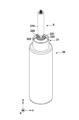
- FIG. 1 shows a schematic configuration of a beverage server 100 according to one embodiment of the present invention.
- the beverage server 100 may include a main body 15 as a supply source for supplying a carbonated beverage CB, and a dispensing nozzle 9 for dispensing the carbonated beverage CB supplied from the main body 15 into a beverage container (not shown).
- the beverage server 100 may include a dispensing head 8 protruding from the main body 15, and the dispensing nozzle 9 may form part of the dispensing head 8.
- the beverage container may be, for example, a container to which a lid can be attached (e.g., a water bottle) or a container to which a lid cannot be attached (e.g., a tumbler), and is not limited to a specific one.
- a beverage may be supplied to the beverage server 100 via the flow path 2.
- the beverage supplied to the beverage server 100 may be water or a beverage other than water.
- the beverage supplied to the beverage server 100 may be a beverage without added carbon dioxide gas or a carbonated beverage with added carbon dioxide gas.
- the beverage supplied to the beverage server 100 may be an alcoholic beverage or a non-alcoholic beverage.
- a filter 1 may be disposed in the flow path 2.
- the main body 15 may include a flow path 16 connected to the flow path 2.
- a valve 3 and a pump 4 may be provided in the flow path 16.
- the main body 15 may include an addition unit (carbonator) 13 that adds carbon dioxide gas to a beverage supplied to the main body 15 to generate a carbonated beverage CB.
- the beverage may be supplied to the addition unit 13 through the flow path 16.
- the addition unit 13 may be configured to dissolve carbon dioxide gas supplied from a carbon dioxide gas supply source (e.g., a carbon dioxide gas cylinder) 11 in the beverage.
- Carbon dioxide gas may be supplied from the carbon dioxide gas supply source 11 to the addition unit 13 via a pressure reducing valve 12.
- the main body 15 may include a cooling tank 14.
- the addition unit 13 may be cooled by a cooling liquid 17 such as water in the cooling tank 14, thereby cooling the carbonated beverage CB.
- the flow path 16 may include a cooling coil 5 immersed in the cooling liquid 17.
- the carbonated beverage CB produced by the addition unit 13 may be supplied to the dispensing head 8 (dispensing nozzle 9) through the flow path 6.
- the flow path 6 may include a cooling coil 7 immersed in the cooling liquid 17.
- the dispensing head 10 may be provided with a positioning member 10 for positioning a beverage container (not shown). A user may position the beverage container by pressing the beverage container against the positioning member 10. In this state, it is preferable from a hygienic standpoint that the mouth of the beverage container does not come into contact with the dispensing head 10.
- the dispensing nozzle 9 may include a tubular member 210 and a guide 220.
- the guide 220 has a guide surface 221. A portion of the guide surface 221 is disposed inside the tubular member 210, and another portion (the lower portion) of the guide surface 221 protrudes below the tubular member 210. The carbonated beverage dispensed from the dispensing nozzle 9 descends inside the tubular member 210 while being guided by the guide surface 221.
- the guide surface 221 has an upper end and a lower end, and the guide surface 221 may be configured to have a gentle slope from a position between the upper end and the lower end toward the lower end. The slope may change smoothly.
- the guide surface 221 may be configured so that the carbonated beverage that passes through its lower end spreads out in a fan shape. In another aspect, the guide surface 221 may be configured so that the carbonated beverage that passes through its lower end spreads radially.
- the guide surface 221 may have a number of grooves 222 arranged to control the flow of the carbonated beverage.
- the maximum dimension of the lower end of the guide surface 221 in a direction along a plane perpendicular to the axial direction of the tubular member 210 is greater than the maximum dimension of the tubular member in the direction along the plane (in this example, the outer diameter).
- the dispensing nozzle 9 may include a tubular member 210 and a guide 220.
- the guide 220 has a guide surface 221. A portion of the guide surface 221 is disposed inside the tubular member 210, and another portion (the lower portion) of the guide surface 221 protrudes below the tubular member 210. The carbonated beverage dispensed from the dispensing nozzle 9 descends inside the tubular member 210 while being guided by the guide surface 221.
- the guide surface 221 has an upper end and a lower end, and the guide surface 221 may be configured to have a gentle slope from a position between the upper end and the lower end toward the lower end. The slope may change smoothly.
- the guide surface 221 may be configured so that the carbonated beverage that passes through its lower end spreads out in a fan shape. From another perspective, the guide surface 221 can be configured so that the carbonated beverage that passes its lower end spreads radially.
- the guide surface 221 is not provided with a groove.
- the maximum dimension of the lower end of the guide surface 221 in a direction along a plane perpendicular to the axial direction of the tubular member 210 is greater than the maximum dimension of the tubular member in the direction along that plane (in this example, the outer diameter).
- the dispensing nozzle 9 may include a tubular member 210 and a guide 220.
- the guide 220 has a guide surface 221. A portion of the guide surface 221 is disposed inside the tubular member 210, and another portion (the lower portion) of the guide surface 221 protrudes below the tubular member 210. The carbonated beverage dispensed from the dispensing nozzle 9 descends inside the tubular member 210 while being guided by the guide surface 221.
- the guide surface 221 has an upper end and a lower end, and the guide surface 221 may be configured to have a gentle slope from a position between the upper end and the lower end toward the lower end. The slope may change smoothly.
- the guide surface 221 may be configured so that the carbonated beverage that passes through its lower end spreads out in a fan shape. In another aspect, the guide surface 221 may be configured so that the carbonated beverage that has passed its lower end spreads radially.
- the guide surface 221 may have a number of grooves 222 arranged to control the flow of the carbonated beverage.
- the guide surface 221 includes a first region 223 that does not have a groove and a second region that extends from the first region 223 to the lower end of the guide surface 221, and the number of grooves 222 may be arranged in the second region.
- the maximum dimension of the lower end of the guide surface 221 in a direction along a plane perpendicular to the axial direction of the tubular member 210 is greater than the maximum dimension of the tubular member in the direction along the plane (in this example, the outer diameter).
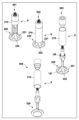
- 5A and 5B show a dispensing nozzle 9 according to a fourth configuration example.
- 501 is an oblique view of the dispensing nozzle 9 with a portion of the tubular portion 210 cut away.
- 502 is an oblique view of the dispensing nozzle 9.
- 503 and 504 are exploded oblique views of the dispensing nozzle 9.
- 505 is an exploded front view of the dispensing nozzle 9.
- 506 is a cross-sectional view of the dispensing nozzle 9.
- the dispensing nozzle 9 may include a tubular member 210 and a guide 220.
- the guide 220 has a guide surface 221.
- a portion of the guide surface 221 is disposed inside the tubular member 210, and another portion (the lower portion) of the guide surface 221 protrudes below the tubular member 210.
- the carbonated beverage dispensed from the dispensing nozzle 9 descends inside the tubular member 210 while being guided by the guide surface 221.
- the guide surface 221 has an upper end UE and a lower end LE, and the guide surface 221 may be configured to have a gentle slope from a position PP between the upper end UE and the lower end LE toward the lower end LE. The slope may change smoothly.
- the guide surface 221 may be configured to spread the carbonated beverage that has passed the lower end LE in a fan shape.
- the guide surface 221 may be configured to spread the carbonated beverage that has passed the lower end LE in a radial shape.
- the guide surface 221 may have a plurality of grooves 222 provided to control the flow of the carbonated beverage.
- the width of the plurality of grooves in a direction perpendicular to the axial direction of the tubular member 210 is, for example, within a range of 1 to 5 mm, preferably within a range of 2 to 3 mm.
- the guide surface 221 may include an overhanging surface OH in a section from the upper end UE to a position PP between the upper end UE and the lower end LE.
- the overhanging surface OH may be located entirely inside the tubular member 210.
- the overhanging surface OH is advantageous for controlling the flow rate of the carbonated beverage.
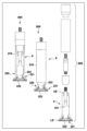
- 6A and 6B show a dispensing nozzle 9 according to a fifth configuration example.
- 601 is an oblique view of the dispensing nozzle 9 with a portion of the tubular portion 210 cut away.
- 602 is an oblique view of the dispensing nozzle 9.
- 603 is an exploded oblique view of the dispensing nozzle 9.
- 604 is a side view of the dispensing nozzle 9 with a portion of the tubular portion 210 cut away.
- 605 is a side view of the dispensing nozzle 9.
- 606 is an exploded side view of the dispensing nozzle 9.
- 607 is a cross-sectional view of the dispensing nozzle 9.
- the dispensing nozzle 9 may include a tubular member 210 and a guide 220.
- the guide 220 has a guide surface 221.
- a portion of the guide surface 221 is disposed inside the tubular member 210, and another portion (the lower portion) of the guide surface 221 protrudes downward from the tubular member 210.
- the carbonated beverage dispensed from the dispensing nozzle 9 descends inside the tube member 210 while being guided by the guide surface 221.
- the guide surface 221 has an upper end UE and a lower end LE, and the guide surface 221 may be configured to have a gentle slope from a position PP between the upper end UE and the lower end LE toward the lower end LE. The slope may change smoothly.
- the guide surface 221 may be configured so that the carbonated beverage that has passed through the lower end LE spreads in a fan shape.
- the guide surface 221 may be configured so that the carbonated beverage that has passed through the lower end LE spreads radially.
- the guide surface 221 may have a plurality of grooves 222 provided to control the flow of the carbonated beverage.
- the width of the plurality of grooves in a direction perpendicular to the axial direction of the tube member 210 is, for example, within a range of 1 to 5 mm, preferably within a range of 2 to 3 mm.
- the flow path of the carbonated beverage inside the cylindrical member 210 can be defined by a part of the inner surface of the cylindrical member 210 and the guide surface 221 in a cross section perpendicular to the axial direction of the cylindrical member 210. In the cross section, another part of the inner surface of the cylindrical member 210 can be in contact with the guide 220.
- 7A and 7B show a dispensing nozzle 9 according to a sixth configuration example.
- 701 is an oblique view of the dispensing nozzle 9 with a portion of the tubular portion 210 cut away.
- 702 is an oblique view of the dispensing nozzle 9.
- 703 is an exploded oblique view of the dispensing nozzle 9.
- 704 is a side view of the dispensing nozzle 9 with a portion of the tubular portion 210 cut away.
- 705 is a side view of the dispensing nozzle 9.
- 706 is an exploded side view of the dispensing nozzle 9.
- 707 is a cross-sectional view of the dispensing nozzle 9.
- the dispensing nozzle 9 may include a tubular member 210 and a guide 220.
- the guide 220 has a guide surface 221.
- a portion of the guide surface 221 is disposed inside the tubular member 210, and another portion (the lower portion) of the guide surface 221 protrudes downward from the tubular member 210.
- the carbonated beverage dispensed from the dispensing nozzle 9 descends inside the cylindrical member 210 while being guided by the guide surface 221.
- the guide surface 221 has an upper end UE and a lower end LE, and the guide surface 221 may be configured to have a gentle inclination from a position PP between the upper end UE and the lower end LE toward the lower end LE. The inclination may change smoothly.
- the guide surface 221 may be configured so that the carbonated beverage that has passed through its lower end LE spreads in a fan shape.
- the guide surface 221 may be configured so that the carbonated beverage that has passed through its lower end LE spreads radially.
- no groove is provided on the guide surface 221.
- the guide surface 221 may include an overhanging surface OH in the section from the upper end UE to the position PP between the upper end UE and the lower end LE.
- the overhanging surface OH is advantageous for controlling the flow rate of the carbonated beverage.
- the flow path of the carbonated beverage inside the cylindrical member 210 can be defined by a part of the inner surface of the cylindrical member 210 and the guide surface 221 in a cross section perpendicular to the axial direction of the cylindrical member 210. In the cross section, another part of the inner surface of the cylindrical member 210 can be in contact with the guide 220.
- 8A, 8B, and 8C show a dispensing nozzle 9 according to a seventh configuration example.
- 801 is an oblique view of the dispensing nozzle 9 with a portion of the tubular portion 210 cut away.
- 802 is an oblique view of the dispensing nozzle 9.
- 803 is an exploded oblique view of the dispensing nozzle 9.
- 804 is a front view of the dispensing nozzle 9 with a portion of the tubular portion 210 cut away.
- 805 is a front view of the dispensing nozzle 9.
- 806 is an exploded front view of the dispensing nozzle 9.
- 807 is a cross-sectional view of the dispensing nozzle 9.
- 808 is a side view of the dispensing nozzle 9.
- the dispensing nozzle 9 may include a tubular member 210 and a guide 220.
- the guide 220 has a guide surface 221.
- a portion of the guide surface 221 is disposed inside the tubular member 210, and another portion (lower portion) of the guide surface 221 protrudes downward from the tubular member 210.
- the carbonated beverage dispensed from the dispensing nozzle 9 descends inside the tubular member 210 while being guided by the guide surface 221.
- the guide surface 221 has an upper end UE and a lower end LE, and the guide surface 221 may be configured to have a gentle slope from a position PP between the upper end UE and the lower end LE toward the lower end LE. The slope may change smoothly.
- the guide surface 221 may be configured so that the carbonated beverage that has passed through the lower end LE spreads in a fan shape. In another aspect, the guide surface 221 may be configured so that the carbonated beverage that has passed through the lower end LE spreads radially.
- the guide surface 221 may have a plurality of grooves 222 provided to control the flow of the carbonated beverage.
- the width of the grooves in the direction perpendicular to the axial direction of the tube member 210 is, for example, in the range of 1 to 5 mm, preferably in the range of 2 to 3 mm.
- the guide surface 221 includes a first region 223 having no grooves and a second region extending from the first region 223 to the lower end of the guide surface 221, and the grooves 222 may be provided in the second region.
- the flow path of the carbonated beverage inside the tube member 210 may be defined by a part of the inner surface of the tube member 210 and the guide surface 221 in a cross section perpendicular to the axial direction of the tube member 210. In the cross section, another part of the inner surface of the tube member 210 may contact the guide 220.
- the guide surface 221 may include an overhanging surface OH in the section from the upper end UE to a position PP between the upper end UE and the lower end LE. The overhanging surface OH is advantageous for controlling the flow rate of the carbonated beverage.
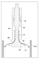
- the guide surface 221 can be configured to have a gentle slope from a position between the upper end UE of the guide surface 221 and the lower end LE of the guide surface 221 toward the lower end LE. This gives a component in the direction toward the container 20 or the inner surface of its mouth 21 to the flow of the carbonated beverage CB supplied from the main body 15.
- the guide surface 221 can give a horizontal component to the flow of the carbonated beverage CB supplied from the main body 15. This allows the carbonated beverage CB supplied from the main body 15 to be discharged from the dispensing nozzle 9 diagonally downward or horizontally toward the container 20 or the inner surface of its mouth 21.
- the loss of carbon dioxide gas from the carbonated beverage CB i.e., the decrease in the GV value, can be effectively suppressed compared to when the carbonated beverage CB is discharged from the dispensing nozzle vertically toward the bottom of the beverage container 20.
Landscapes
- Devices For Dispensing Beverages (AREA)
Priority Applications (5)
| Application Number | Priority Date | Filing Date | Title |
|---|---|---|---|
| CN202480021389.XA CN120858070A (zh) | 2023-03-30 | 2024-01-29 | 饮料服务器及注出喷嘴 |
| EP24778640.3A EP4691963A1 (en) | 2023-03-30 | 2024-01-29 | Beverage server and dispensing nozzle |
| AU2024247905A AU2024247905A1 (en) | 2023-03-30 | 2024-01-29 | Beverage server and pouring nozzle |
| JP2024575848A JP7660779B2 (ja) | 2023-03-30 | 2024-01-29 | 飲料サーバーおよび注出ノズル |
| US19/340,717 US20260022005A1 (en) | 2023-03-30 | 2025-09-25 | Beverage server and pouring nozzle |
Applications Claiming Priority (2)
| Application Number | Priority Date | Filing Date | Title |
|---|---|---|---|
| JP2023-056272 | 2023-03-30 | ||
| JP2023056272 | 2023-03-30 |
Related Child Applications (1)
| Application Number | Title | Priority Date | Filing Date |
|---|---|---|---|
| US19/340,717 Continuation US20260022005A1 (en) | 2023-03-30 | 2025-09-25 | Beverage server and pouring nozzle |
Publications (1)
| Publication Number | Publication Date |
|---|---|
| WO2024202494A1 true WO2024202494A1 (ja) | 2024-10-03 |
Family
ID=92905012
Family Applications (1)
| Application Number | Title | Priority Date | Filing Date |
|---|---|---|---|
| PCT/JP2024/002710 Ceased WO2024202494A1 (ja) | 2023-03-30 | 2024-01-29 | 飲料サーバーおよび注出ノズル |
Country Status (7)
| Country | Link |
|---|---|
| US (1) | US20260022005A1 (https=) |
| EP (1) | EP4691963A1 (https=) |
| JP (1) | JP7660779B2 (https=) |
| CN (1) | CN120858070A (https=) |
| AU (1) | AU2024247905A1 (https=) |
| TW (1) | TW202438431A (https=) |
| WO (1) | WO2024202494A1 (https=) |
Citations (4)
| Publication number | Priority date | Publication date | Assignee | Title |
|---|---|---|---|---|
| JP2006513937A (ja) * | 2003-03-13 | 2006-04-27 | ヨーンクル,マシュー,シー. | 飲料注ぎ出し装置 |
| JP2015124006A (ja) | 2013-12-27 | 2015-07-06 | サッポロビール株式会社 | 注出部材、カラン及びサーバ |
| US20160340081A1 (en) * | 2015-05-21 | 2016-11-24 | James Cicarelli | Container with laminar flow |
| JP2023056272A (ja) | 2021-10-07 | 2023-04-19 | 日本電産コパル株式会社 | 折り畳み型情報端末 |
-
2024
- 2024-01-29 CN CN202480021389.XA patent/CN120858070A/zh active Pending
- 2024-01-29 AU AU2024247905A patent/AU2024247905A1/en active Pending
- 2024-01-29 JP JP2024575848A patent/JP7660779B2/ja active Active
- 2024-01-29 WO PCT/JP2024/002710 patent/WO2024202494A1/ja not_active Ceased
- 2024-01-29 EP EP24778640.3A patent/EP4691963A1/en active Pending
- 2024-02-29 TW TW113107320A patent/TW202438431A/zh unknown
-
2025
- 2025-09-25 US US19/340,717 patent/US20260022005A1/en active Pending
Patent Citations (4)
| Publication number | Priority date | Publication date | Assignee | Title |
|---|---|---|---|---|
| JP2006513937A (ja) * | 2003-03-13 | 2006-04-27 | ヨーンクル,マシュー,シー. | 飲料注ぎ出し装置 |
| JP2015124006A (ja) | 2013-12-27 | 2015-07-06 | サッポロビール株式会社 | 注出部材、カラン及びサーバ |
| US20160340081A1 (en) * | 2015-05-21 | 2016-11-24 | James Cicarelli | Container with laminar flow |
| JP2023056272A (ja) | 2021-10-07 | 2023-04-19 | 日本電産コパル株式会社 | 折り畳み型情報端末 |
Non-Patent Citations (1)
| Title |
|---|
| See also references of EP4691963A1 |
Also Published As
| Publication number | Publication date |
|---|---|
| AU2024247905A1 (en) | 2025-10-23 |
| US20260022005A1 (en) | 2026-01-22 |
| JPWO2024202494A1 (https=) | 2024-10-03 |
| TW202438431A (zh) | 2024-10-01 |
| JP7660779B2 (ja) | 2025-04-11 |
| EP4691963A1 (en) | 2026-02-11 |
| CN120858070A (zh) | 2025-10-28 |
Similar Documents
| Publication | Publication Date | Title |
|---|---|---|
| CN100509608C (zh) | 饮料分配装置和饮料分配系统 | |
| US5186363A (en) | Liquid mixing and dispensing nozzle | |
| EP3363768B1 (en) | A valve nozzle for dispensing liquid | |
| GB2510400A (en) | Foam Dispenser | |
| JP7660779B2 (ja) | 飲料サーバーおよび注出ノズル | |
| KR102241410B1 (ko) | 음료 주출 콕, 밸브 로드 및 음료 디스펜서 | |
| JP6704338B2 (ja) | 炭酸水コック | |
| CA3287544A1 (en) | Beverage server and pouring nozzle | |
| JP5672777B2 (ja) | 飲料供給装置の飲料ノズル | |
| JP2010083530A (ja) | 脈動防止具付きペットボトル | |
| WO2016013152A1 (ja) | 高炭酸飲料の供給方法 | |
| JP7257666B2 (ja) | ポストミックス式炭酸飲料サーバの注出ノズル | |
| JP2001170463A (ja) | 炭酸水製造装置 | |
| JP7410468B2 (ja) | 注出ノズルおよび飲料サーバー | |
| EP4378880A1 (en) | Regulator for controlling the flow of carbonated drinks | |
| JP2026050217A (ja) | トリガー式液体吐出器及びトリガー式スプレー容器 | |
| JPS6212408Y2 (https=) | ||
| JP2002284295A (ja) | ビール注出装置 | |
| JPWO2024202494A5 (https=) | ||
| JP6459377B2 (ja) | 飲料供給装置のマルチバルブ | |
| JP7357439B2 (ja) | 吐出器 | |
| AU2020299016A1 (en) | Beverage dispenser | |
| JP2003320231A (ja) | 気液溶解方法および装置 | |
| CN105520642B (zh) | 饮料供应装置的多路阀 | |
| JP2020050361A (ja) | 飲料注出装置 |
Legal Events
| Date | Code | Title | Description |
|---|---|---|---|
| 121 | Ep: the epo has been informed by wipo that ep was designated in this application |
Ref document number: 24778640 Country of ref document: EP Kind code of ref document: A1 |
|
| WWE | Wipo information: entry into national phase |
Ref document number: 2024575848 Country of ref document: JP |
|
| WWE | Wipo information: entry into national phase |
Ref document number: 202480021389.X Country of ref document: CN |
|
| WWE | Wipo information: entry into national phase |
Ref document number: 202547095959 Country of ref document: IN |
|
| WWE | Wipo information: entry into national phase |
Ref document number: AU2024247905 Country of ref document: AU |
|
| ENP | Entry into the national phase |
Ref document number: 2024247905 Country of ref document: AU Date of ref document: 20240129 Kind code of ref document: A |
|
| WWP | Wipo information: published in national office |
Ref document number: 202480021389.X Country of ref document: CN |
|
| WWE | Wipo information: entry into national phase |
Ref document number: 2024778640 Country of ref document: EP |
|
| NENP | Non-entry into the national phase |
Ref country code: DE |
|
| WWP | Wipo information: published in national office |
Ref document number: 202547095959 Country of ref document: IN |
|
| ENP | Entry into the national phase |
Ref document number: 2024778640 Country of ref document: EP Effective date: 20251030 |
|
| ENP | Entry into the national phase |
Ref document number: 2024778640 Country of ref document: EP Effective date: 20251030 |
|
| ENP | Entry into the national phase |
Ref document number: 2024778640 Country of ref document: EP Effective date: 20251030 |
|
| ENP | Entry into the national phase |
Ref document number: 2024778640 Country of ref document: EP Effective date: 20251030 |
|
| ENP | Entry into the national phase |
Ref document number: 2024778640 Country of ref document: EP Effective date: 20251030 |
|
| ENP | Entry into the national phase |
Ref document number: 2024778640 Country of ref document: EP Effective date: 20251030 |
|
| ENP | Entry into the national phase |
Ref document number: 2024778640 Country of ref document: EP Effective date: 20251030 |
|
| ENP | Entry into the national phase |
Ref document number: 2024778640 Country of ref document: EP Effective date: 20251030 |
|
| WWP | Wipo information: published in national office |
Ref document number: 2024778640 Country of ref document: EP |