WO2024202390A1 - 切削工具及び切削加工物の製造方法 - Google Patents
切削工具及び切削加工物の製造方法 Download PDFInfo
- Publication number
- WO2024202390A1 WO2024202390A1 PCT/JP2024/000756 JP2024000756W WO2024202390A1 WO 2024202390 A1 WO2024202390 A1 WO 2024202390A1 JP 2024000756 W JP2024000756 W JP 2024000756W WO 2024202390 A1 WO2024202390 A1 WO 2024202390A1
- Authority
- WO
- WIPO (PCT)
- Prior art keywords
- cutting tool
- cutting
- opening
- cutting insert
- Prior art date
- Legal status (The legal status is an assumption and is not a legal conclusion. Google has not performed a legal analysis and makes no representation as to the accuracy of the status listed.)
- Ceased
Links
Images




Classifications
-
- B—PERFORMING OPERATIONS; TRANSPORTING
- B23—MACHINE TOOLS; METAL-WORKING NOT OTHERWISE PROVIDED FOR
- B23C—MILLING
- B23C5/00—Milling-cutters
- B23C5/28—Features relating to lubricating or cooling
- B23C5/283—Cutting inserts with internal coolant channels
-
- B—PERFORMING OPERATIONS; TRANSPORTING
- B23—MACHINE TOOLS; METAL-WORKING NOT OTHERWISE PROVIDED FOR
- B23C—MILLING
- B23C5/00—Milling-cutters
- B23C5/02—Milling-cutters characterised by the shape of the cutter
- B23C5/06—Face-milling cutters, i.e. having only or primarily a substantially flat cutting surface
-
- B—PERFORMING OPERATIONS; TRANSPORTING
- B23—MACHINE TOOLS; METAL-WORKING NOT OTHERWISE PROVIDED FOR
- B23C—MILLING
- B23C2210/00—Details of milling cutters
- B23C2210/16—Fixation of inserts or cutting bits in the tool
- B23C2210/168—Seats for cutting inserts, supports for replacable cutting bits
-
- B—PERFORMING OPERATIONS; TRANSPORTING
- B23—MACHINE TOOLS; METAL-WORKING NOT OTHERWISE PROVIDED FOR
- B23C—MILLING
- B23C2222/00—Materials of tools or workpieces composed of metals, alloys or metal matrices
- B23C2222/16—Cermet
-
- B—PERFORMING OPERATIONS; TRANSPORTING
- B23—MACHINE TOOLS; METAL-WORKING NOT OTHERWISE PROVIDED FOR
- B23C—MILLING
- B23C2222/00—Materials of tools or workpieces composed of metals, alloys or metal matrices
- B23C2222/28—Details of hard metal, i.e. cemented carbide
Definitions
- the coolant is mainly used to cool the cutting insert. Therefore, the coolant is sprayed toward the cutting edge or rake face of the cutting insert, where heat is likely to be generated during cutting.
- a cutting tool includes a holder extending from the tip to the rear end and having a pocket located on the tip side, and a cutting insert located in the pocket.
- the cutting insert has a polygonal upper surface, a polygonal lower surface located opposite the upper surface and usable as a seating surface, a plurality of side surfaces connected to the upper surface and the lower surface, and a cutting edge located at the intersection of the upper surface and the side surfaces.
- the upper surface has a plurality of corners and a plurality of sides.
- the plurality of side surfaces have a plurality of corner side surfaces extending from the corners toward the lower surface, and a plurality of main side surfaces extending from the sides toward the lower surface.
- the plurality of main side surfaces have a first main side surface and a second main side surface.
- the pocket has a seating surface facing the lower surface, a first constraint surface facing the first main side surface, a second constraint surface facing the second main side surface, and a concave portion located between the first constraint surface and the second constraint surface, away from the cutting insert, and facing one of the plurality of corner side surfaces.
- the holder further has a coolant passage extending from the rear end side toward the pocket. The coolant passage has one or more first openings that open into the concave portion.
- a method for manufacturing a machined product includes a step of rotating a cutting tool, a step of bringing the rotating cutting tool into contact with a workpiece, and a step of removing the cutting tool from the workpiece.
- FIG. 2 is a schematic perspective view of a cutting tool according to an example of the present disclosure, as viewed from the side.
- FIG. 2 is a schematic perspective view of a cutting tool according to an example of the present disclosure, as viewed from the tip side.
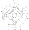
- FIG. 2 is a schematic front view of a cutting tool according to an example of the present disclosure, as viewed from the tip side.
- FIG. 2 is a schematic perspective view of a holder according to an example of the present disclosure, as viewed from the tip side.
- FIG. 5 is an enlarged view of a V portion in FIG. 4 .
- FIG. 2 is a schematic front view of a holder according to an example of the present disclosure, as viewed from the tip side.
- FIG. 7 is an enlarged view of a portion VII in FIG. 6 .
- FIG. 2 is a schematic side view of a holder according to an example of the present disclosure, as viewed from the side.
- FIG. 9 is an enlarged view of part IX in FIG. 8 .
- FIG. 2 is a schematic perspective view of an example cutting insert of the present disclosure.
- FIG. 2 is a schematic diagram of a cutting insert according to an example of the present disclosure, viewed from the top surface side.
- 1A to 1C are schematic diagrams illustrating a method for manufacturing a machined product according to an example of the present disclosure.
- 1A to 1C are schematic diagrams illustrating a method for manufacturing a machined product according to an example of the present disclosure.
- 1A to 1C are schematic diagrams illustrating a method for manufacturing a machined product according to an example of the present disclosure.
- chips generated during cutting get into the pockets, they may get caught between the seating surface of the pocket and the cutting insert when replacing the cutting insert, which could reduce the accuracy of attaching the cutting insert to the holder.
- This requires a process to remove the chips that have gotten into the pockets when replacing the cutting insert.
- the process of manually removing chips that have gotten into the pockets is cumbersome.
- it is not easy to automate the chip removal process. To automate the chip removal process, it is necessary to recognize the chips using image processing, but because the pockets are wet with coolant, it is difficult to recognize them using image processing.
- each of the drawings referred to below shows a simplified view of only the components necessary to explain the embodiments. Therefore, the cutting tool of the example of the present disclosure may include any components not shown in each of the drawings referred to. Furthermore, the dimensions of the components in each drawing do not faithfully represent the actual dimensions of the components and the dimensional ratios of each member, etc.
- the rotation direction refers to the rotation direction of the cutting tool.
- Orthogonal does not mean strictly orthogonal, but means that an error of about ⁇ 5 degrees is allowed.
- Parallel does not mean strictly parallel, but means that an error of about ⁇ 5 degrees is allowed.
- Fig. 1 is a schematic perspective view of the cutting tool 10 according to the example of the present disclosure, as viewed from the side.
- Fig. 2 is a schematic perspective view of the cutting tool 10 according to the example of the present disclosure, as viewed from the tip side.
- Fig. 3 is a schematic front view of the cutting tool 10 according to the example of the present disclosure, as viewed from the tip side.
- Fig. 4 is a schematic perspective view of the holder 12 according to the example of the present disclosure, as viewed from the tip side.
- Fig. 5 is an enlarged view of the V portion in Fig. 4.
- FIG. 6 is a schematic front view of the holder 12 of an example of the present disclosure, as viewed from the tip side.
- FIG. 7 is an enlarged view of portion VII in FIG. 6.
- FIG. 8 is a schematic side view of the holder 12 of an example of the present disclosure, as viewed from the side.
- FIG. 9 is an enlarged view of portion IX in FIG. 8.
- FIG. 10 is a schematic perspective view of the cutting insert 18 of an example of the present disclosure.
- FIG. 11 is a schematic view of the cutting insert 18 of an example of the present disclosure, as viewed from the top side.
- a cutting tool 10 is used for cutting a workpiece W (see Figure 12), in particular for milling such as face milling or end milling.
- the cutting tool 10 is a rotary tool such as a milling tool that can rotate around a rotation axis RD.
- the cutting tool 10 may include a holder 12 that is attached to the spindle of a processing machine such as a milling machine.
- the holder 12 may be cylindrical and extend from a tip 12a to a rear end 12b along the rotation axis RD. Examples of materials for the holder 12 include metals such as stainless steel, carbon steel, cast iron, and aluminum alloys.
- the holder 12 may have a plurality of notches 14 spaced apart in the circumferential direction on its outer circumferential surface side.
- the plurality of notches 14 may be equally spaced apart in the circumferential direction, or may be unequally spaced apart in the circumferential direction.
- the number of notches 14 may be one.
- the holder 12 may also have a concave pocket 16 located on the wall surface of the notch 14 facing the rotation direction T.
- the holder 12 may have a plurality of pockets 16 spaced apart in the circumferential direction on its outer circumferential surface side.
- the plurality of pockets 16 may be equally spaced apart in the circumferential direction, or may be unequally spaced apart in the circumferential direction.
- the number of pockets 16 may be one.
- the cutting tool 10 may include a cutting insert 18 located in a pocket 16 of the holder 12.
- the cutting insert 18 may be located only in one or more selected pockets 16 in the holder 12.
- the cutting insert 18 may also be fixed to the pocket 16 of the holder 12 by a mounting screw B.
- the cutting insert 18 may also be fixed to the pocket 16 of the holder 12 by a clamping member.
- the cutting insert 18 may have a rectangular upper surface 20 and a rectangular lower surface 22 located opposite the upper surface 20.
- the upper surface 20 and the lower surface 22 may each be a polygonal shape other than a rectangle, such as a triangular shape.
- a rectangular shape is not limited to a rectangular shape in the strict sense, but includes a shape that can be seen as a rectangular shape overall.
- a polygonal shape is not limited to a polygonal shape in the strict sense, but includes a shape that can be seen as a polygonal shape overall.
- the upper surface 20 and the lower surface 22 may each have a rotationally symmetric shape at a fixed angle around the central axis 18c of the cutting insert 18.
- the upper surface 20 and the lower surface 22 may each have a shape that is inverted symmetric on the front and back.
- the cutting insert 18 may have a rotationally symmetric shape at a fixed angle around the central axis 18c of the cutting insert 18, or may have a shape that is inverted symmetric on the front and back.
- the cutting insert 18 may have multiple side surfaces 24 located between the upper surface 20 and the lower surface 22.
- the multiple side surfaces 24 may be connected to the upper surface 20 and the lower surface 22.
- the multiple side surfaces 24 may function as clearance surfaces and may be parallel to the central axis 18c of the cutting insert 18.
- the cutting insert 18 may be a so-called negative type cutting insert with a clearance angle of 0 degrees.
- the cutting insert 18 may have a through hole 26 that penetrates from the upper surface 20 to the lower surface 22.
- the through hole 26 may be a hole for inserting a mounting screw B (see FIG. 1).
- One opening of the through hole 26 may be located in the center of the upper surface 20, and the other opening of the through hole 26 may be located in the center of the lower surface 22.
- the central axis of the through hole 26 may coincide with the central axis 18c of the cutting insert 18.
- the cutting insert 18 may have an upper cutting edge 28 located at the intersection of the upper surface 20 and the side surface 24, and a lower cutting edge 30 at the intersection of the lower surface 22 and the side surface 24.
- the cutting insert 18 may be a double-sided insert having an upper cutting edge 28 and a lower cutting edge 30.
- the upper cutting edge 28 may be located at the entire intersection of the upper surface 20 and the side surface 24, or may be located at a portion of the intersection.
- the lower cutting edge 30 may be located at the entire intersection of the lower surface 22 and the side surface 24, or may be located at a portion of the intersection.
- the upper surface 20 and the lower surface 22 can each be used as a seating surface.
- the lower surface 22 may be used as a seating surface for mounting to the pocket 16 of the holder 12.
- the upper surface 20 may be used as a seating surface.
- “upper” and “lower” may be understood interchangeably in the following description.
- the upper surface 20 When the lower surface 22 is used as a seating surface, the upper surface 20 may function as a scooping surface, and when the upper surface 20 is used as a seating surface, the lower surface 22 may function as a scooping surface.
- the upper surface 20 may have a plurality of corner portions 32 and a plurality of side portions 34.
- the side portions 34 may be located between adjacent corner portions 32.
- the side portions 34 may be linear in top view.
- the plurality of side surfaces 24 may have a plurality of corner side surfaces 36 extending from the corner portions 32 toward the lower surface 22, and a plurality of main side surfaces 38 extending from the side portions 34 toward the lower surface 22.
- the plurality of main side surfaces 38 may have a first main side surface 38a and a second main side surface 38b.
- the first main side surface 38a and the second main side surface 38b may be adjacent to each other via one corner side surface 36.
- the lower surface 22 may have portions that correspond to the corners 32 and sides 34 of the upper surface 20.
- the configurations of the portions that correspond to the corners 32 and sides 34 of the lower surface 22 may be the same as the configurations of the corners 32 and sides 34 of the upper surface 20, except that the positional relationship in the vertical direction is reversed.
- the cutting insert 18 may be made of, for example, a cemented carbide or a cermet.
- the composition of the cemented carbide may be, for example, WC-Co, which is produced by adding cobalt (Co) powder to tungsten carbide (WC) and sintering the mixture; WC-TiC-Co, which is produced by adding titanium carbide (TiC) to WC-Co; or WC-TiC-TaC-Co, which is produced by adding tantalum carbide (TaC) to WC-TiC-Co.
- a cermet is a sintered composite material in which a ceramic component is combined with a metal, and specific examples of such sintered composite materials include titanium carbide (TiC) or titanium nitride (TiN) or other titanium compounds as the main component.
- the surface of the cutting insert 18 may be coated with a coating by chemical vapor deposition (CVD) or physical vapor deposition (PVD) techniques, with the coating having a composition such as titanium carbide (TiC), titanium nitride (TiN), titanium carbonitride (TiCN), or alumina (Al 2 O 3 ).
- CVD chemical vapor deposition
- PVD physical vapor deposition
- the pocket 16 of the holder 12 may have a seating surface 40 that faces the lower surface 22 used as the seating surface of the cutting insert 18.
- the seating surface 40 faces the upper surface 20.
- the seating surface 40 may have a flat abutment portion 40a that abuts against the lower surface 22 of the cutting insert 18, and a curved portion 40b that is positioned around the abutment portion 40a and curved concavely.
- the pocket 16 of the holder 12 may also have a screw hole 42 for screwing in the mounting screw B.
- the screw hole 42 may open in the center of the abutment portion 40a of the seating surface 40.
- the pocket 16 of the holder 12 may have a first restraining surface 44 facing the first main side surface 38a of the cutting insert 18.
- the first restraining surface 44 may have a flat abutment portion 44a that abuts against the first main side surface 38a of the cutting insert 18, and recessed portions 44b located on the upper side (the opening side of the pocket 16) and the lower side (the side opposite the opening side of the pocket 16) of the abutment portion 44a.
- the recessed portion 44b in the example shown in Figs. 4 to 7 is curved in a concave shape, and may be referred to as a recess.
- the abutment portion 44a of the first restraining surface 44 may be perpendicular to the abutment portion 40a of the seat surface 40.
- the pocket 16 of the holder 12 may have a second restraining surface 46 facing the second main side surface 38b of the cutting insert 18.
- the second restraining surface 46 may have a flat abutment portion 46a that abuts against the second main side surface 38b of the cutting insert 18.
- the second restraining surface 46 may have recessed portions 46b located on the upper side (the opening side of the pocket 16) and the lower side (the side opposite the opening side of the pocket 16) of the abutment portion 46a.
- the recessed portions 46b in the examples shown in Figures 4 to 7 are curved in a concave shape and may be referred to as recesses.
- the abutment portion 46a of the second restraining surface 46 may be perpendicular to the abutment portion 46a of the seat surface 40.
- the abutment portion 46a of the second restraining surface 46 may intersect the abutment portion 44a of the first restraining surface 44.
- the pocket 16 of the holder 12 may have a concave portion 48 located between the first restraint surface 44 and the second restraint surface 46 and facing one of the corner side surfaces 36 of the cutting insert 18.
- the concave portion 48 may be spaced from the cutting insert 18.
- the holder 12 may have a coolant passage 50 located therein for supplying coolant (cooling fluid) to the cutting insert 18.
- the coolant passage 50 may extend from the rear end 12b of the holder 12 toward the pocket 16.
- a cleaning liquid may flow through the coolant passage 50 instead of coolant.
- a coolant may flow through the coolant passage 50 as a cleaning liquid.
- coolants examples include water-insoluble oils and water-soluble oils.
- water-insoluble oils include cutting oils such as oil-based, inactive extreme pressure, and active extreme pressure.
- water-soluble oils include cutting oils such as emulsions, solubles, and solutions. Coolants are not limited to liquids, and may be gases such as inert gases.
- the coolant passage 50 may have one or more first openings 52 that open into the concave portion 48 of the pocket 16.
- the coolant passage 50 in the examples shown in Figures 4 to 7 has multiple first openings 52.
- the multiple first openings 52 of the coolant passage 50 may be located closer to the seat surface 40 of the pocket 16 than the upper surface 20 of the cutting insert 18. In other words, the distance between the multiple first openings 52 and the seat surface 40 may be smaller than the distance between the upper surface 20 and the seat surface 40.
- the multiple first openings 52 of the coolant passage 50 may open toward the corner side surface 36 of the cutting insert 18.
- the multiple first openings 52 of the coolant passage 50 may open toward the seat surface 40 of the pocket 16.
- the coolant passage 50 may have one or more second openings 54 located away from the pocket 16 in the cutout 14.
- the second openings 54 of the coolant passage 50 may be located on the wall surface opposite the side facing the direction of rotation T in the cutout 14.
- the second openings 54 of the coolant passage 50 may open toward the upper surface 20 of the cutting insert 18.
- the second openings 54 of the coolant passage 50 may be located forward of the cutting insert 18 in the direction of rotation T.
- the opening area of the second openings 54 of the coolant passage 50 may be larger than the opening area of the first openings 52.
- the coolant passage 50 may have multiple third openings 56 that open to the seat surface 40 of the pocket 16.
- the third openings 56 of the coolant passage 50 may open to the curved portion 40b of the seat surface 40 of the pocket 16.
- the third openings 56 of the coolant passage 50 may open to the abutment portion 40a of the seat surface 40.
- the third opening 56 may overlap the cutting insert 18 when the upper surface 20 is viewed from the front. In this case, the third opening 56 of the coolant passage 50 may be blocked by the lower surface 22 of the cutting insert 18.
- the third opening 56 of the coolant passage 50 is not limited to the above configuration.
- the third opening 56 may open toward the first constraining surface 44 and the second constraining surface 46. In such a case, it becomes easier to clean the first constraining surface 44 and the second constraining surface 46 when replacing the cutting insert 18, and the installation accuracy of the cutting insert 18 can be easily improved.
- the coolant passage 50 may have one or more fourth openings 58 that open into the first restraining surface 44 of the pocket 16.
- the coolant passage 50 in the example shown in Figures 4 to 7 has multiple fourth openings 58.
- the multiple fourth openings 58 of the coolant passage 50 may open into the recessed portion 44b of the first restraining surface 44 of the pocket 16.
- the multiple fourth openings 58 of the coolant passage 50 may open toward the seat surface 40 of the pocket 16.
- the multiple fourth openings 58 of the coolant passage 50 may open to the abutment portion 44a of the first restraining surface 44 of the pocket 16.
- the multiple fourth openings 58 of the coolant passage 50 may overlap the cutting insert 18 when the first restraining surface 44 is viewed from the front. In this case, the multiple fourth openings 58 may be blocked by the first main side surface 38a of the cutting insert 18.
- the coolant passage 50 may have one or more fifth openings 60 that open into the second restraining surface 46 of the pocket 16.
- the coolant passage 50 in the examples shown in Figures 4 to 7 has multiple fifth openings 60.
- the multiple fifth openings 60 of the coolant passage 50 may open into the recessed portion 46b of the second restraining surface 46 of the pocket 16.
- the multiple fifth openings 60 of the coolant passage 50 may open toward the seat surface 40 of the pocket 16.
- the plurality of fifth openings 60 of the coolant passage 50 may open to the abutment portion 46a of the second restraining surface 46 of the pocket 16.
- the plurality of fifth openings 60 of the coolant passage 50 may overlap the cutting insert 18 when the second restraining surface 46 is viewed from the front. In this case, the plurality of fifth openings 60 may be blocked by the second main side surface 38b of the cutting insert 18.
- the coolant flow passage 50 of the holder 12 has one or more first openings 52 that open into the concave portion 48 of the pocket 16. Therefore, during cleaning of the pocket 16 of the holder 12, cleaning liquid is sprayed from the first openings 52 of the coolant flow passage 50, thereby removing chips adhering to the pocket 16.
- the cutting tool 10 of the embodiment disclosed herein when replacing the cutting insert 18, it is possible to prevent chips from becoming caught between the seat surface 40 of the pocket 16 and the cutting insert 18. As a result, it is possible to ensure sufficient mounting accuracy of the cutting insert 18 relative to the holder 12, thereby improving the machining accuracy of the cutting process of the workpiece W (see FIG. 12).
- coolant passage 50 has a second opening 54 that opens toward the upper surface 20, as in the examples shown in Figures 1, 2, 4, and 5, coolant is sprayed from the second opening 54 of the coolant passage 50 toward the upper surface 20 of the cutting insert 18 during cutting of the workpiece W. This allows the cutting insert 18 to be cooled during cutting of the workpiece W, thereby increasing the durability of the cutting insert 18.
- coolant passage 50 has one or more third openings 56 that open into the seat surface 40 of the pocket 16
- coolant is ejected from the third openings 56 of the coolant passage 50 toward the cutting insert 18 during cutting of the workpiece W.
- This allows the cutting insert 18 to be cooled and the durability of the cutting insert 18 to be increased.
- chips are less likely to get into the curved portion 40b of the seat surface.
- coolant flow passage 50 has one or more fourth openings 58 that open to the first restraining surface 44 of the pocket 16
- coolant is ejected from the fourth openings 58 of the coolant flow passage 50 toward the cutting insert 18 during cutting of the workpiece W. This allows the cutting insert 18 to be cooled, thereby increasing the durability of the cutting insert 18.
- the coolant when the fourth opening 58 of the coolant flow passage 50 is blocked by the first main side surface 38a of the cutting insert 18, the coolant can be used efficiently.
- cleaning liquid is sprayed from the fourth opening 58, so that cutting chips adhering to the seat surface 40 of the pocket 16 of the holder 12 can be removed.
- the outflow of cleaning liquid from the fourth opening 58 is suppressed during cutting processing, the amount and flow rate of coolant sprayed from the first opening 52 and/or the second opening 54 can be increased.
- coolant flow passage 50 has one or more fifth openings 60 that open to the second restraining surface 46 of the pocket 16
- coolant is ejected from the fifth openings 60 of the coolant flow passage 50 toward the cutting insert 18 during cutting of the workpiece W. This allows the cutting insert 18 to be cooled, thereby increasing the durability of the cutting insert 18.
- the coolant when the fifth opening 60 of the coolant flow passage 50 is blocked by the second main side surface 38b of the cutting insert 18, the coolant can be used efficiently.
- cleaning liquid is sprayed from the fifth opening 60, so that cutting chips adhering to the seat surface 40 of the pocket 16 of the holder 12 can be removed.
- the outflow of cleaning liquid from the fifth opening 60 is suppressed during cutting processing, the amount and flow rate of coolant sprayed from the first opening 52 and/or the second opening 54 can be increased.
- Fig. 12 to Fig. 14 are schematic diagrams for explaining a method for manufacturing a machined product according to an example of the present disclosure.
- the manufacturing method of the machined product of the example of the present disclosure is a method for manufacturing a machined product M, which is a workpiece W that has been machined, and includes a first step, a second step, and a third step.
- the first step is a step of rotating the cutting tool 10.
- the second step is a step of bringing the rotating cutting tool 10 into contact with the workpiece W.
- the third step is a step of moving the cutting tool 10 away from the workpiece W.
- materials for the workpiece W include aluminum alloys, stainless steel, carbon steel, alloy steel, cast iron, and non-ferrous metals.
- the cutting tool 10 is rotated in the rotation direction T while being moved in the direction of the arrow FD to approach the workpiece W (first step). Then, the cutting insert 18 of the rotating cutting tool 10 is moved in the direction of the arrow FD while being brought into contact with the workpiece W (second step). As a result, the cutting tool 10 performs a turning process, which is one of the cutting processes for the workpiece W, and a machined surface Wf is formed on the workpiece W as in the example shown in Figure 13.
- the cutting tool 10 is further moved in the direction of the arrow FD and separated from the workpiece W (third step). This completes the cutting of the workpiece W, and a machined product M can be produced, which is the workpiece W that has been machined. Because the cutting tool 10 has excellent cutting capabilities for the reasons described above, a machined product M with excellent machining precision can be produced.
- the cutting insert 18 of the cutting tool 10 may be repeatedly brought into contact with different locations of the workpiece W while the cutting tool 10 is rotating.
- the cutting tool 10 is brought closer to the workpiece W, but since it is sufficient that the cutting tool 10 and the workpiece W are relatively close to each other, for example, the workpiece W may be brought closer to the cutting tool 10. The same process is carried out when the cutting tool 10 is moved away from the workpiece W.
- a cutting tool in one embodiment, includes a holder extending from a tip to a rear end and having a pocket located on the tip side, and a cutting insert located in the pocket.
- the cutting insert has a polygonal upper surface, a polygonal lower surface located opposite the upper surface and usable as a seating surface, a plurality of side surfaces connected to the upper surface and the lower surface, and a cutting edge located at the intersection of the upper surface and the side surfaces.
- the upper surface has a plurality of corners and a plurality of sides.
- the plurality of side surfaces have a plurality of corner side surfaces extending from the corners toward the lower surface, and a plurality of main side surfaces extending from the sides toward the lower surface.
- the plurality of main side surfaces include a first main side surface and a second main side surface.
- the pocket has a seat surface facing the lower surface, a first constraint surface facing the first main side surface, a second constraint surface facing the second main side surface, and a concave portion located between the first constraint surface and the second constraint surface, away from the cutting insert, and facing one of the corner side surfaces.
- the holder further has a coolant passage extending from the rear end side toward the pocket. The coolant passage has one or more first openings that open into the concave portion.
- the coolant passage may further have one or more second openings located away from the pocket and opening toward the upper surface.
- the opening area of the second opening may be larger than the opening area of the first opening.
- the first opening may open toward the seat surface.
- the third opening may overlap the cutting insert when the top surface is viewed from the front.
- the coolant flow passage may further have one or more fourth openings that open to the first restraint surface.
- the fourth opening may open toward the seat surface.
- the coolant flow passage may further have one or more fifth openings that open to the second restraint surface.
- the fifth opening overlaps with the cutting insert when the second restraint surface is viewed from the front.
- a method for manufacturing a machined product includes the steps of rotating a cutting tool according to any one of (1) to (14), bringing the rotating cutting tool into contact with a workpiece, and removing the cutting tool from the workpiece.
Landscapes
- Engineering & Computer Science (AREA)
- Mechanical Engineering (AREA)
- Cutting Tools, Boring Holders, And Turrets (AREA)
Priority Applications (2)
| Application Number | Priority Date | Filing Date | Title |
|---|---|---|---|
| DE112024001480.1T DE112024001480T5 (de) | 2023-03-30 | 2024-01-15 | Schneidwerkzeug und verfahren zur herstellung eines maschinell bearbeiteten produkts |
| JP2025509773A JPWO2024202390A1 (https=) | 2023-03-30 | 2024-01-15 |
Applications Claiming Priority (2)
| Application Number | Priority Date | Filing Date | Title |
|---|---|---|---|
| JP2023-056535 | 2023-03-30 | ||
| JP2023056535 | 2023-03-30 |
Publications (1)
| Publication Number | Publication Date |
|---|---|
| WO2024202390A1 true WO2024202390A1 (ja) | 2024-10-03 |
Family
ID=92904774
Family Applications (1)
| Application Number | Title | Priority Date | Filing Date |
|---|---|---|---|
| PCT/JP2024/000756 Ceased WO2024202390A1 (ja) | 2023-03-30 | 2024-01-15 | 切削工具及び切削加工物の製造方法 |
Country Status (3)
| Country | Link |
|---|---|
| JP (1) | JPWO2024202390A1 (https=) |
| DE (1) | DE112024001480T5 (https=) |
| WO (1) | WO2024202390A1 (https=) |
Citations (3)
| Publication number | Priority date | Publication date | Assignee | Title |
|---|---|---|---|---|
| JP2010076088A (ja) * | 2008-09-01 | 2010-04-08 | Mitsubishi Materials Corp | 切削工具 |
| JP2012524669A (ja) * | 2009-04-22 | 2012-10-18 | クレアー・インコーポレーテッド | 回転切断ツールの間接冷却 |
| DE102014211415A1 (de) * | 2014-06-13 | 2015-12-17 | NUBIUS GROUP Präzisionswerkzeuge GmbH | Fräswerkzeug mit Kühlung hinter Wendeschneidplatte |
-
2024
- 2024-01-15 JP JP2025509773A patent/JPWO2024202390A1/ja active Pending
- 2024-01-15 WO PCT/JP2024/000756 patent/WO2024202390A1/ja not_active Ceased
- 2024-01-15 DE DE112024001480.1T patent/DE112024001480T5/de active Pending
Patent Citations (3)
| Publication number | Priority date | Publication date | Assignee | Title |
|---|---|---|---|---|
| JP2010076088A (ja) * | 2008-09-01 | 2010-04-08 | Mitsubishi Materials Corp | 切削工具 |
| JP2012524669A (ja) * | 2009-04-22 | 2012-10-18 | クレアー・インコーポレーテッド | 回転切断ツールの間接冷却 |
| DE102014211415A1 (de) * | 2014-06-13 | 2015-12-17 | NUBIUS GROUP Präzisionswerkzeuge GmbH | Fräswerkzeug mit Kühlung hinter Wendeschneidplatte |
Also Published As
| Publication number | Publication date |
|---|---|
| JPWO2024202390A1 (https=) | 2024-10-03 |
| DE112024001480T5 (de) | 2026-01-22 |
Similar Documents
| Publication | Publication Date | Title |
|---|---|---|
| JP6668485B2 (ja) | 切削工具用ホルダ及び切削工具、並びにそれらを用いた切削加工物の製造方法 | |
| US10456847B2 (en) | Cutting tool and method for manufacturing machined product | |
| JP6921230B2 (ja) | 切削工具及び切削加工物の製造方法 | |
| JP7304989B2 (ja) | 切削インサート、切削工具及び切削加工物の製造方法 | |
| JP6467049B2 (ja) | 切削工具及び切削加工物の製造方法 | |
| JP6462126B2 (ja) | 切削インサート、切削工具及びこれを用いた切削加工物の製造方法 | |
| JP6467014B2 (ja) | 切削工具及び切削加工物の製造方法 | |
| JP7630641B2 (ja) | 切削インサート、切削工具、及び切削加工物の製造方法 | |
| JP6691549B2 (ja) | ドリル用ホルダ、ドリル及び切削加工物の製造方法 | |
| JP6875546B2 (ja) | 切削工具及び切削加工物の製造方法 | |
| CN112930236B (zh) | 切削刀片、切削刀具以及切削加工物的制造方法 | |
| WO2024202390A1 (ja) | 切削工具及び切削加工物の製造方法 | |
| JP6920811B2 (ja) | 切削工具用ホルダ、切削工具及び切削加工物の製造方法 | |
| JP7045460B2 (ja) | 切削工具及び切削加工物の製造方法 | |
| JP6467048B2 (ja) | 切削工具及び切削加工物の製造方法 | |
| WO2023176619A1 (ja) | 切削インサート、切削工具、及び切削加工物の製造方法 | |
| JP6825854B2 (ja) | 切削工具及び切削加工物の製造方法 | |
| JP7746403B2 (ja) | ホルダ、切削工具及び切削加工物の製造方法 | |
| JP7706641B2 (ja) | 切削インサート、切削工具、及び切削加工物の製造方法 | |
| WO2025182455A1 (ja) | 切削インサート、切削工具及び切削加工物の製造方法 | |
| WO2026034060A1 (ja) | 切削インサート、切削工具及び切削加工物の製造方法 | |
| JP2025133477A (ja) | 切削インサート、切削工具及び切削加工物の製造方法 | |
| WO2025074852A1 (ja) | 切削インサート、切削工具、および切削加工物の製造方法 | |
| WO2024195284A1 (ja) | 切削工具及び切削加工物の製造方法 | |
| WO2024202230A1 (ja) | 切削インサート、切削工具及び切削加工物の製造方法 |
Legal Events
| Date | Code | Title | Description |
|---|---|---|---|
| 121 | Ep: the epo has been informed by wipo that ep was designated in this application |
Ref document number: 24778536 Country of ref document: EP Kind code of ref document: A1 |
|
| ENP | Entry into the national phase |
Ref document number: 2025509773 Country of ref document: JP Kind code of ref document: A |
|
| WWE | Wipo information: entry into national phase |
Ref document number: 2025509773 Country of ref document: JP |
|
| WWE | Wipo information: entry into national phase |
Ref document number: 112024001480 Country of ref document: DE |
|
| WWP | Wipo information: published in national office |
Ref document number: 112024001480 Country of ref document: DE |
|
| 122 | Ep: pct application non-entry in european phase |
Ref document number: 24778536 Country of ref document: EP Kind code of ref document: A1 |