WO2024202243A1 - 干渉観察装置及び光学調整方法 - Google Patents
干渉観察装置及び光学調整方法 Download PDFInfo
- Publication number
- WO2024202243A1 WO2024202243A1 PCT/JP2023/042790 JP2023042790W WO2024202243A1 WO 2024202243 A1 WO2024202243 A1 WO 2024202243A1 JP 2023042790 W JP2023042790 W JP 2023042790W WO 2024202243 A1 WO2024202243 A1 WO 2024202243A1
- Authority
- WO
- WIPO (PCT)
- Prior art keywords
- interference
- light
- observation
- image
- optical
- Prior art date
- Legal status (The legal status is an assumption and is not a legal conclusion. Google has not performed a legal analysis and makes no representation as to the accuracy of the status listed.)
- Ceased
Links
Images









Classifications
-
- G—PHYSICS
- G02—OPTICS
- G02B—OPTICAL ELEMENTS, SYSTEMS OR APPARATUS
- G02B21/00—Microscopes
- G02B21/36—Microscopes arranged for photographic purposes or projection purposes or digital imaging or video purposes including associated control and data processing arrangements
- G02B21/361—Optical details, e.g. image relay to the camera or image sensor
-
- G—PHYSICS
- G02—OPTICS
- G02B—OPTICAL ELEMENTS, SYSTEMS OR APPARATUS
- G02B21/00—Microscopes
-
- G—PHYSICS
- G02—OPTICS
- G02B—OPTICAL ELEMENTS, SYSTEMS OR APPARATUS
- G02B21/00—Microscopes
- G02B21/24—Base structure
- G02B21/26—Stages; Adjusting means therefor
-
- G—PHYSICS
- G02—OPTICS
- G02B—OPTICAL ELEMENTS, SYSTEMS OR APPARATUS
- G02B21/00—Microscopes
- G02B21/36—Microscopes arranged for photographic purposes or projection purposes or digital imaging or video purposes including associated control and data processing arrangements
-
- G—PHYSICS
- G02—OPTICS
- G02B—OPTICAL ELEMENTS, SYSTEMS OR APPARATUS
- G02B7/00—Mountings, adjusting means, or light-tight connections, for optical elements
- G02B7/28—Systems for automatic generation of focusing signals
Definitions
- One aspect of the present disclosure relates to an interference observation device and an optical adjustment method for an interference observation device.
- Patent Document 1 describes an interference observation device that includes a light source, an interference optical system that branches the light output from the light source into a first branched light and a second branched light, reflects the first branched light on an object to be observed, combines the first branched light with the second branched light (reference light), and outputs the combined light, a light receiving unit that receives the combined light and outputs a detection signal, and an image acquisition unit that acquires an interference image based on the detection signal.
- the above-mentioned interference observation device is used for surface observation, in which the surface of an object to be observed is observed.
- interference observation it is also conceivable to use interference observation to perform internal observation, in which the inside of an object to be observed is observed.
- the object to be observed is a device with a cap member
- the surface of the device can be observed through the cap member by using light with a wavelength that passes through the cap member.
- optical adjustments such as adjusting the focal position of the objective lens and adjusting the optical path length of the reference light are required during observation.
- Such optical adjustments must be performed quickly and accurately.
- one method of adjusting the focal position of the objective lens in internal observation is to scan the focal position over the entire thickness direction of the object to align the focal position with the observation position within the object, but this method is difficult to achieve high speed.
- this method after scanning the focal position, it takes several hundred milliseconds for the vibration of the optical path length on the object side (the optical path length of the first branched light) to settle on the order of nanometers, and this waiting time for settling can be an obstacle to achieving high speed.
- one aspect of the present disclosure aims to provide an interference observation device and an optical adjustment method that can perform optical adjustment quickly and with high accuracy.
- the interference observation device is an interference observation device that includes: [1] "a light source that outputs light; an interference optical system that has a movable reference mirror, divides the light output from the light source into a first light and a second light, and outputs interference light between the first light reflected by an observation object and the second light reflected by the reference mirror; an image sensor that detects the interference light; and a processing unit that acquires an interference image based on the detection result of the interference light and performs an optical adjustment process for optical adjustment related to observation of the observation object, the processing unit acquiring a plurality of interference images with different optical path length differences between the first light and the second light by changing the optical path length of the second light, and performing the optical adjustment process based on the plurality of interference images.”
- optical adjustment processing is performed based on multiple interference images with different optical path length differences obtained by changing the optical path length of the second light, so optical adjustment can be performed quickly and accurately.
- optical adjustment can be performed quickly and accurately compared to, for example, the above-mentioned method in which the focal position of the objective lens is scanned over the entire thickness direction of the observed object.
- the interference observation device may be the interference observation device described in [1], in which the processing unit calculates an evaluation value for each of the plurality of interference images and performs the optical adjustment process based on the evaluation values of the plurality of interference images.
- the optical adjustment process can be performed preferably.
- the interference observation device may be the interference observation device described in [2], [3] in which "the multiple interference images include a first interference image and a second interference image in which the optical path length difference is different from each other, and the processing unit performs the optical adjustment process based on the difference between a first evaluation value, which is the evaluation value calculated based on the first interference image, and a second evaluation value, which is the evaluation value calculated based on the second interference image.”
- the optical adjustment process can be performed preferably.
- the interference observation device may be the interference observation device described in [4] "in which the second interference image is acquired after the first interference image is acquired, and the processing unit performs the optical adjustment if the absolute value of the difference is greater than a predetermined value after the second interference image is acquired, and does not perform the optical adjustment if the absolute value of the difference is equal to or less than the predetermined value.”
- the optical adjustment process can be preferably performed.
- the interference observation device may be the interference observation device described in [5] "in which, when the processing unit performs the optical adjustment after the second interference image is acquired, the processing unit performs the optical adjustment according to the magnitude relationship between the first evaluation value and the second evaluation value.”
- the optical adjustment process can be preferably performed.
- the interference observation device may be the interference observation device described in [6] or [5], in which "when the processing unit performs the optical adjustment after the second interference image is acquired, the processing unit performs the optical adjustment by an amount corresponding to the magnitude of the difference between the first evaluation value and the second evaluation value.”
- the optical adjustment process can be preferably performed.
- the interference observation device may be [7] "the interference observation device according to any one of [2] to [6], in which the processing unit calculates the evaluation value based at least on an amplitude image corresponding to the interference image.”
- the evaluation value can be calculated preferably.
- the interference observation device may be [8] "an interference observation device according to any one of [2] to [7], in which the processing unit calculates the evaluation value based at least on the amount of curvature of interference fringes in a phase image corresponding to the interference image.”
- the evaluation value can be calculated preferably.
- the interference observation device may be [9] "an interference observation device according to any one of [1] to [8], in which the processing unit acquires the multiple interference images having different optical path length differences by moving the reference mirror to change the optical path length of the second light.” In this case, multiple interference images can be acquired advantageously.
- the interference observation device may be [10] "an interference observation device according to any one of [1] to [9], in which the amount of change in the optical path length of the second light differs between the multiple interference images by a value greater than the wavelength of the light output from the light source.”
- the optical adjustment process can be preferably performed.
- the interference observation device may be [11] "the interference observation device according to any one of [1] to [10], in which the interference optical system further has an objective lens, and the optical adjustment includes adjusting the relative position between the objective lens and the observation object.” In this case, the relative position between the objective lens and the observation object can be adjusted.
- the interference observation device may be [12] "the interference observation device according to any one of [1] to [11], in which the optical adjustment includes adjusting the optical path length of the second light by moving the reference mirror.” In this case, the optical path length of the second light can be adjusted.
- the interference observation device may be [13] "the interference observation device according to any one of [1] to [12], in which the interference optical system further has a reference objective lens that guides the second light to the reference mirror, and the optical adjustment includes adjusting the position of the reference objective lens.” In this case, the position of the reference objective lens can be adjusted.
- the interference observation device may be [14] "the interference observation device according to any one of [1] to [13], in which the observation position of the observation object along a plane intersecting the direction in which the first light is incident on the observation object is the same among the multiple interference images.”
- optical adjustment processing can be performed based on the multiple interference images acquired at the same observation position.
- the interference observation device may be [15] "an interference observation device according to any one of [1] to [13], in which the observation positions of the observation object along a plane intersecting the direction in which the first light is incident on the observation object are different between the multiple interference images.”
- optical adjustment processing can be performed based on the multiple interference images acquired at different observation positions.
- the interference observation device may be [16] "an interference observation device according to any one of [1] to [15], further comprising a stage for placing the observation object, the stage being movable at least along a plane intersecting the direction in which the first light is incident on the observation object, and the processing unit performing the optical adjustment process based on the multiple interference images in response to the movement of the stage along the plane.”
- the observation position can be changed by moving the observation object while performing the optical adjustment.
- the interference observation device may be [17] "the interference observation device described in [16], in which the interference optical system further has an objective lens, and the processing unit performs the optical adjustment process for adjusting the relative position between the objective lens and the observation object based on the multiple interference images in response to the movement of the stage along the plane.”
- the observation object can be moved to change the observation position while adjusting the relative position between the objective lens and the observation object.
- the interference observation device may be an interference observation device according to any one of [1] to [17], further comprising: [18] "a stage for placing the observation object, the stage being movable at least along a plane intersecting the direction in which the first light is incident on the observation object, the plurality of interference images include a first interference image and a second interference image having different optical path length differences, and the processing unit alternately executes a first process and a second process, where in the first process, the processing unit acquires the first interference image, performs the optical adjustment process based on the first interference image and the second interference image acquired in the immediately preceding second process, and moves the stage along the plane, and in the second process, the processing unit acquires the second interference image, performs the optical adjustment process based on the second interference image and the first interference image acquired in the immediately preceding first process, and moves the stage along the plane.”
- the optical adjustment process can be performed by sequential processing.
- An interference observation device further comprises, [19] "a stage for placing the observation object, the stage being movable at least along a plane intersecting the direction in which the first light is incident on the observation object, and a first storage area and a second storage area, the plurality of interference images include a first interference image and a second interference image having mutually different optical path length differences, and the processing unit executes a first process, a second process, and a third process in parallel, where in the first process, the processing unit acquires first data for generating the first interference image from the imaging element, stores the first data in the first storage area, and then performs a process of moving the stage along the plane, and acquires second data for generating the second interference image from the imaging element, and stores the second data in the first storage area.
- the processing unit alternately executes a process of generating the first interference image based on the first data acquired in the first process and storing a first evaluation value corresponding to the first interference image in the second storage area, and a process of generating the second interference image based on the second data acquired in the first process and storing a second evaluation value corresponding to the second interference image in the second storage area.
- the processing unit performs the optical adjustment process based on the first evaluation value and the second evaluation value acquired immediately before each time the first evaluation value or the second evaluation value is stored in the second storage area in the second process. In this case, the optical adjustment process can be performed by parallel processing.
- the interference observation device may be [20] "an interference observation device according to any one of [1] to [19], further comprising a piezoelectric element for moving the reference mirror and a motor for moving the target of the optical adjustment, and the processing unit uses the piezoelectric element to move the reference mirror to change the optical path length of the second light, thereby acquiring the multiple interference images with different optical path length differences, and performing the optical adjustment using the motor.”
- the optical adjustment process can be performed using the piezoelectric element and the motor.
- the interference observation device may be [21] "an interference observation device according to any one of [1] to [19], further comprising a stepping motor for moving the reference mirror, the stepping motor being operable in a first mode and a second mode having a step angle larger than that of the first mode, and the processing unit driving the stepping motor in the first mode to move the reference mirror and change the optical path length of the second light, thereby acquiring the multiple interference images having different optical path length differences, and driving the stepping motor in the second mode to perform the optical adjustment.”
- the optical adjustment process can be performed using the stepping motor.
- the interference observation device may be [22] "the interference observation device described in any one of [1] to [21], in which the interference optical system further has an objective lens, the interference observation device has an AF light source that outputs light, and further includes a surface AF unit that acquires light output from the AF light source and reflected by the surface of the observation object via the interference optical system, and adjusts the relative position between the objective lens of the interference optical system and the surface of the observation object based on the acquisition result.” In this case, the relative position between the objective lens and the surface of the observation object can be adjusted by the surface AF unit.
- the interference observation device may be the interference observation device described in [22], [23] which further includes a stage for placing the observation object, the stage being movable at least along a plane intersecting the direction in which the first light is incident on the observation object, and the processing unit performs the optical adjustment process for adjusting the relative position between the objective lens and the observation object based on the multiple interference images in response to the movement of the stage along the plane, and the optical adjustment process for adjusting the optical path length of the second light by moving the reference mirror.
- the optical adjustment process for adjusting the relative position between the objective lens and the observation object, and the optical adjustment process for adjusting the optical path length of the second light can be performed while moving the observation object.
- the optical adjustment method is [24] "an optical adjustment method for performing optical adjustment related to observation of an object to be observed in an interference observation device that includes a light source that outputs light, an interference optical system that has a movable reference mirror, divides the light output from the light source into first light and second light, and outputs interference light between the first light reflected by an object to be observed and the second light reflected by the reference mirror, and an image sensor that detects the interference light, and in which an interference image is obtained based on the detection result of the interference light, the optical adjustment method including a step of obtaining a plurality of interference images having different optical path length differences between the first light and the second light by changing the optical path length of the second light, and performing an optical adjustment process for the optical adjustment based on the plurality of interference images.”
- optical adjustment processing is performed based on multiple interference images with different optical path length differences obtained by changing the optical path length of the second light, so optical adjustment can be performed quickly and accurately.
- optical adjustment can be performed quickly and accurately compared to, for example, the above-mentioned method in which the focal position of the objective lens is scanned over the entire thickness direction of the observed object.
- the optical adjustment method according to one aspect of the present disclosure may be [25] "the optical adjustment method described in [24], in which, in the step, the plurality of interference images are obtained based on a detection result of the interference light between the first light reflected by the surface of the observation object and the second light reflected by the reference mirror.”
- optical adjustment can be performed in the case of surface observation, in which the surface of the observation object is observed.
- the optical adjustment method according to one aspect of the present disclosure may be [26] "the optical adjustment method described in [24], in which, in the step, the plurality of interference images are obtained based on a detection result of the interference light between the first light reflected inside the observation object and the second light reflected by the reference mirror.”
- optical adjustment can be performed in the case of internal observation, in which the inside of the observation object is observed.
- the optical adjustment method according to one aspect of the present disclosure may be, [27] "the optical adjustment method according to any one of [24] to [26], in which, in the step, the object to be observed is moved along a plane intersecting the direction in which the first light is incident on the object to be observed, thereby changing an observation position relative to the object to be observed along the plane, and the optical adjustment process is performed based on the multiple interference images in response to the movement of the object to be observed along the plane.”
- the optical adjustment process can be performed while the object to be observed is being moved.
- the optical adjustment method according to one aspect of the present disclosure may be [28] "the optical adjustment method according to any one of [24] to [27], in which the interference optical system further has an exchangeable objective lens, and in the step, when the objective lens is exchanged, the optical adjustment process is performed to adjust the optical path length of the second light by moving the reference mirror based on the multiple interference images.”
- optical adjustment can be performed when the objective lens is exchanged.
- the optical adjustment method may be the optical adjustment method described in any one of [24] to [28], in which, by changing the optical path length of the second light, the multiple interference images having different optical path length differences between the first light and the second light are obtained, and an optical adjustment process for the optical adjustment is performed based on the multiple interference images as a fine adjustment process, the direction in which the first light is incident on the observation object is defined as an incident direction, and multiple interference images are obtained while scanning the focal position of the objective lens over the entire observation object in the incident direction, and the focal position is adjusted based on the obtained results as a focal position adjustment process, the fine adjustment process or the focal position adjustment process is performed according to the observation position of the observation object along a plane intersecting the incident direction as the observation object moves along the plane.
- an increase in takt time can be suppressed by intermittently performing the focal position adjustment process, which requires time.
- an interference observation device and an optical adjustment method that can perform optical adjustment quickly and with high accuracy.
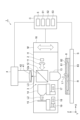
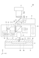
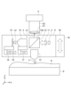
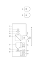
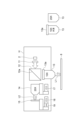
- FIG. 1 is a configuration diagram of an interference observation apparatus according to an embodiment.
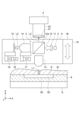
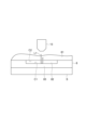
- FIG. 13 is a diagram for explaining internal observation.
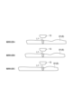
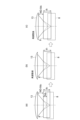
- 10 is a diagram for explaining the relationship between the amount of movement of the objective lens and the amount of change in the optical path length of the second light.
- FIG. 11A and 11B are diagrams for explaining an adjustment amount when an observation object has a plurality of layers.
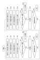
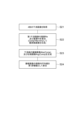
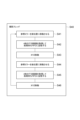
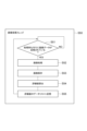
- 10 is a flowchart for explaining a process executed in the interference observation apparatus.
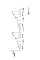
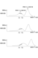
- FIG. 2 is a diagram for explaining the operation of the interference observation apparatus.
- FIG. 13 is a diagram showing an example of an acquired interference image.
- 1A to 1C are diagrams illustrating examples of a real part image, an imaginary part image, an amplitude image, and a phase image.
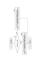
- FIG. 10 is a flowchart for explaining a process of calculating an evaluation value based on an acquired interference image.
- 11 is a flowchart illustrating a focus adjustment process.
- FIG. 11 is a diagram for explaining focus adjustment.
- FIG. 11 is a diagram for explaining focus adjustment.
- FIG. 11 is a diagram for explaining a focus lock.
- FIG. 11 is a diagram for explaining a focus lock.
- 13A and 13B are diagrams for explaining another example of the operation of the interference observation apparatus.
- 13 is a flowchart for explaining another example of the processing executed in the interference observation apparatus.
- 13 is a flowchart for explaining another example of the processing executed in the interference observation apparatus.
- 13 is a flowchart for explaining another example of the processing executed in the interference observation apparatus.
- 13 is a flowchart for explaining another example of the processing executed in the interference observation apparatus.
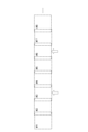
- FIG. 11 is a table for explaining a method of acquiring an interference image.
- FIG. 11 is a diagram for explaining another example of the operation of the interference observation apparatus.
- 13 is a table for explaining another example of optical adjustment.
- FIG. 13 is a configuration diagram of another example of an interference observation apparatus.
- 23A to 23C are diagrams for explaining the relationship between the focus movement amount and the change amount of the optical path length in the interference observation apparatus shown in FIG. 22.
- 11A and 11B are diagrams for explaining a method of calculating an evaluation value based on an amount of curvature in a phase image.
- 11A and 11B are diagrams for explaining an application example of the optical adjustment process.
- FIG. 1 is a diagram for explaining surface observation.
- FIG. 11 is a diagram for explaining another example of the operation of the interference observation apparatus.
- FIG. 1 is a diagram for explaining surface observation.
- FIG. 11 is a diagram for explaining another example of the operation of the interference observation apparatus.
- 11A and 11B are diagrams for explaining optical adjustment when replacing an objective lens.
- 10 is a flowchart for explaining an example of a process when replacing an objective lens.
- FIG. 13 is a diagram showing an example in which an adapter is attached to an objective lens.
- FIG. 11 is a diagram for explaining adjustment of a lens barrel mechanical difference.
- the interference observation device 1 includes a light source 2, an interference optical system 3, an image sensor 4, a processing unit 5, and a stage S.
- the interference observation device 1 is an interference microscope for observing an observation object 8 arranged on the stage S using the interference of light.
- the observation object 8 is, for example, a semiconductor device, but may also be other industrial samples formed from metal, glass, resin, liquid crystal, polymer compounds, etc.
- the observation object 8 may also be a biological sample such as a cell or a cell mass. The following description will be given by setting the X direction, the Y direction perpendicular to the X direction, and the Z direction perpendicular to the X and Y directions as shown in Figs. 1 and 2.
- the interference observation device 1 is configured to be able to perform surface observation, which observes the surface (outer surface) of the observation object 8, as well as internal observation, which observes the inside of the observation object 8. As shown in Figures 1 and 2, in internal observation, an observation object surface R located within the observation object 8 is observed.
- the observation object 8 is a semiconductor device with a cap portion, and has a first layer 81, a second layer 82, and a third layer 83.
- the first layer 81 is a resin layer (cap portion), the second layer 82 is an air layer, and the third layer 83 is a semiconductor layer (device layer).
- the first layer 81 to the third layer 83 are arranged (stacked) in the order of the third layer 83, the second layer 82, and the first layer 81, and the observation object 8 is arranged on the stage S so that the third layer 83 is in contact with the stage S.
- the observation object surface R is set at any of the interfaces between the first layer 81, the second layer 82, and the third layer 83. For example, in the example of FIG. 1, the observation object surface R is set at the interface between the second layer 82 and the third layer 83, and in the example of FIG.
- the observation object surface R is set at the interface between the first layer 81 and the second layer 82.
- the observation object surface R can be observed through the first layer 81.
- the light source 2 outputs incoherent light.
- the light source 2 is, for example, a lamp-based light source such as a halogen lamp, an LED (Light emitting diode) light source, an SLD (Superluminescent diode) light source, an ASE (Amplified spontaneous emission) light source, etc.
- the interference optical system 3 (interference observation device 1) is configured as a Linnik interference type.
- the interference optical system 3 has a lens 11, a beam splitter 12, an objective lens 13, a reference objective lens 14, and a reference mirror 15.
- the interference optical system 3 is arranged in a housing H together with the light source 2, and constitutes an optical module M.
- the optical module M can be moved along the Z direction by a predetermined actuator 16.
- the Z direction is a direction parallel to the optical axis of the objective lens 13, and is a direction parallel to the direction in which the first light L1 described later is incident on the observation object 8.
- the lens 11 collimates the light output from the light source 2.
- the beam splitter 12 is, for example, a prism having an optical surface 12a, and splits the light collimated by the lens 11 into a first light L1 and a second light L2 at the optical surface 12a.
- the beam splitter 12 outputs the first light L1 to the objective lens 13 and outputs the second light L2 to the reference objective lens 14.
- the first light L1 reflected by the observation surface R of the observation object 8 enters the optical surface 12a via the objective lens 13
- the second light L2 reflected by the reference mirror 15 enters the optical surface 12a via the reference objective lens 14.
- the first light L1 and the second light L2 are combined at the optical surface 12a to become an interference light L3.
- the interference optical system 3 outputs the interference light L3 to the image sensor 4.
- the objective lens 13 focuses the first light L1 output from the beam splitter 12 onto the observation object 8 placed on the stage S.
- the objective lens 13 also receives the first light L1 reflected by the observation surface R of the observation object 8.
- the objective lens 13 outputs the incident first light L1 to the beam splitter 12.
- the reference objective lens 14 guides the second light L2 output from the beam splitter 12 to the reference mirror 15 and focuses it on the reference mirror 15.
- the reference objective lens 14 also outputs the second light L2 reflected by the reference mirror 15 to the beam splitter 12.
- the reference mirror 15 reflects the second light L2 output from the reference objective lens 14 back to the reference objective lens 14.
- the stepping motor 17 moves the reference objective lens 14 along the optical axis direction of the second light L2 perpendicular to the Z direction (e.g., the X direction).
- the stepping motor 18 and the piezoelectric element 19 move the reference mirror 15 along the optical axis direction of the second light L2.
- the response time of the stepping motors 17 and 18 is greater than 10 msec, and the response time of the piezoelectric element 19 is less than 1 msec. That is, the response time of the piezoelectric element 19 is shorter than the response time of the stepping motors 17 and 18.
- the stroke (minimum movement distance) of the stepping motors 17 and 18 is several mm, and the stroke of the piezoelectric element 19 is about 2 ⁇ m. That is, the stroke of the piezoelectric element 19 is smaller than the stroke of the stepping motors 17 and 18.
- the number of times that the stepping motors 17 and 18 are driven in their lifetime is less than 1 million times, and the number of times that the piezoelectric element 19 is driven in their lifetime is more than 10 billion times. That is, the number of times that the piezoelectric element 19 is driven in their lifetime is greater than the number of times that the stepping motors 17 and 18 are driven in their lifetime.
- the imaging element 4 is, for example, an image sensor (camera) such as a CCD area image sensor or a CMOS area image sensor.
- the imaging element 4 detects (images) the interference light L3 output from the interference optical system 3 (beam splitter 12).
- a lens 41 and a lens barrel 42 are arranged between the imaging element 4 and the interference optical system 3.
- the lens 41 forms an image of the interference light L3 output from the interference optical system 3 on the imaging surface of the imaging element 4.
- the lens 41 is housed in the lens barrel 42.
- the lens barrel 42 is formed, for example, in a cylindrical shape, and is fixed to the imaging element 4 so as to surround the imaging surface.
- the processing unit 5 is connected to be able to communicate with each part of the interference observation device 1, including the light source 2, the interference optical system 3, the image sensor 4, and the stage S, and acquires an interference image based on the detection result of the interference light L3 at the image sensor 4.
- the processing unit 5 also performs optical adjustment processing for optical adjustment related to observation of the observation object 8 using the interference observation device 1.
- the interference image and the processing performed by the processing unit 5 will be described later.
- the processing unit 5 is composed of, for example, a computer C including a processor (CPU) and storage media such as RAM and ROM.
- the computer C includes a storage area 51.
- Computer C further includes an input unit 52 that accepts input of information, and a display unit 53 that displays information.
- the input unit 52 is, for example, a device that accepts user operation input, such as a mouse or a keyboard.
- the display unit 53 is, for example, a display that displays images.
- the input unit 52 and the display unit 53 may be commonly configured, for example, by a touch panel.
- the processing unit 5, memory area 51, input unit 52, and display unit 53 are configured by a single device, but at least one of them may be configured by a different device, such as a mobile terminal.
- the stage S is a stage for placing the observation object 8, and is movable along an XY plane perpendicular to the Z direction in which the first light L1 is incident on the observation object 8. This makes it possible in the interference observation apparatus 1 to observe the observation object 8 (to obtain an interference image) while moving the stage S along the XY plane, that is, while changing the observation position of the observation object 8. [Example of operation of interference observation device]
- the processing unit 5 performs an optical adjustment process for optical adjustment related to the observation of the observation object 8.
- optical adjustments can be the adjustment of the relative position between the objective lens 13 and the observation object 8, and the optical path length of the second light L2 (reference light).
- the actuator 16 moves the objective lens 13 along the Z direction to adjust the position of the objective lens 13 relative to the observation object 8, and as a result, the focal position of the objective lens 13 is adjusted.
- the stepping motors 17 and 18 move the reference objective lens 14 and the reference mirror 15 to adjust the optical path length of the second light L2 (the optical path length difference between the first light L1 and the second light L2).
- Such optical adjustments are necessary, for example, for the following reasons.
- the adjustment amounts calculated based on the nominal values were 256 ⁇ m for the objective lens 13 and 340 ⁇ m for the reference mirror 15, but the adjustment amounts calculated based on the actual measurements were 270 ⁇ m for the objective lens 13 and 365 ⁇ m for the reference mirror 15.
- the adjustment amounts calculated based on the nominal values were 629 ⁇ m for the objective lens 13 and 961 ⁇ m for the reference mirror 15, but the adjustment amounts calculated based on the actual measurements were 590 ⁇ m for the objective lens 13 and 927 ⁇ m for the reference mirror 15.
- the adjustment amount calculated based on the nominal value there is a discrepancy between the adjustment amount calculated based on the nominal value and the adjustment amount calculated based on the actual measurement value, and adjustment based only on the nominal value cannot perform good optical adjustment.
- the thickness and refractive index of the first layer 81 may change depending on the observation position, which may also cause errors in the focus position of the objective lens 13 and the optical path length of the second light L2, making it difficult to obtain a good interference image. Therefore, the interference observation device 1 performs an optical adjustment process described below.
- the relationship between the movement amount of the objective lens 13 and the change amount of the optical path length of the second light L2 will be described.
- the focus position of the objective lens 13 is assumed to be on the front surface, and as shown by the solid line, the distance between the observation object 8 and the objective lens 13 is shortened by ⁇ d, and the focus position is assumed to be on the back surface.
- ⁇ d d/n 1
- the increase in the optical path length of the first light L1 is expressed by formula (1).
- the adjustment amount based on the above-mentioned nominal value can be calculated by this method.
- the adjustment based on the nominal value can also be applied to the case where the observation object 8 has multiple layers.
- FIG. 4 shows an example where the observation object 8 has three layers.
- ⁇ d expressed by formula (2) compared to the state where the focus is on the upper surface of the first layer.
- the increase amount ⁇ OPD of the optical path length of the first light L1 is expressed by the following formula (3): In theory, it is sufficient to adjust the optical path length of the second light L2 to be longer by this increase amount.
- the above calculations make it possible to adjust the distance and optical path length between the observation object 8 and the objective lens 13 based on nominal values, even when multiple layers with different refractive indices are present.
- a process (optical adjustment method) executed in the interference observation device 1 will be described.
- a first interference image and a second interference image having different optical path length differences between the first light L1 and the second light L2 are obtained by changing the optical path length of the second light L2, and the focus position of the objective lens 13 is adjusted based on the first interference image and the second interference image.
- the first interference image is obtained when the reference mirror 15 is located at the front position (e.g., a first position close to the reference objective lens 14), and the second interference image is obtained when the reference mirror 15 is located at the rear position (e.g., a second position farther from the reference objective lens 14 than the front position).
- the state of the interference observation device 1 at the start of processing is not limited, but may be, for example, a state in which the focus position of the objective lens 13 and the optical path length of the second light L2 have been adjusted by a coarse adjustment process based on the nominal values of the thickness and refractive index of the first to third layers 81 to 83 of the observation object 8.
- the coarse adjustment process the focus position of the objective lens 13 and the optical path length of the second light L2 are adjusted based on the thickness, refractive index, and arrangement order of the first to third layers 81 to 83 so that an interference image of the observation object surface R specified by the user is obtained.
- the process described below is a fine adjustment process for performing optical adjustment with greater precision than the coarse adjustment process.
- step S7 the processing unit 5 determines whether the current observation position is the final observation position (step S8). If the current observation position is the final observation position in step S8 (YES in step S8), the processing ends. On the other hand, if the current observation position is not the final observation position in step S8 (NO in step S8), the processing unit 5 proceeds to processing in step S9.
- step S9 the processing unit 5 controls the piezoelectric element 19 to move the reference mirror 15 from the front position to the rear position. Then, the imaging element 4 captures images to obtain four interference images (step S10). Then, the processing unit 5 constructs (obtains) one second interference image based on the four interference images obtained in step S10 (step S11). Then, the processing unit 5 calculates a second evaluation value based on the second interference image obtained in step S11 (step S12). The processing unit 5 overwrites and stores the second evaluation value calculated in step S12 in an area for storing second evaluation values in the memory area 51.
- step S15 the processing unit 5 determines whether the current observation position is the final observation position (step S16). If the current observation position is the final observation position in step S16 (YES in step S16), the processing ends. On the other hand, if the current observation position is not the final observation position in step S16 (NO in step S16), the processing unit 5 returns to the processing of step S1.
- the first processing consisting of steps S1 to S8 and the second processing consisting of steps S9 to S16 are repeatedly executed alternately until the observation position reaches the final observation position.
- the reference mirror 15 moves between a front position and a rear position (steps S1, S9), and at each position, the image sensor 4 captures images to obtain four interference images (steps S2, S10).
- a focus adjustment process optical adjustment process
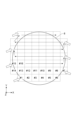
- the stage S moves along the XY plane (steps S7, S15). It is preferable that the amount of movement of the stage S is a distance slightly smaller than the width of one field of view. By performing such an operation, it is possible to capture multiple images and spatially connect these images to generate an entire image.
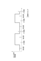
- FIG. 6 shows the timing of image capture (exposure) by the image sensor 4 and the timing of movement of the stage S.
- FIG. 6 shows the amount of movement of the piezoelectric element 19.
- the piezoelectric element 19 is moved finely in accordance with the timing of capturing the four interference images.
- the optical path length difference between the first light L1 and the second light L2 is different between the four interference images.
- the amount of change in the optical path length of the second light L2 differs by a value greater than the wavelength ⁇ of the light output from the light source 2. That is, the distance between the front position and the rear position is greater than the wavelength ⁇ .
- the amount of change in the optical path length of the second light L2 differs by a value smaller than the wavelength ⁇ . That is, the amount of movement of the reference mirror 15 to acquire the four interference images is smaller than the wavelength ⁇ and smaller than the distance between the front position and the rear position. Specifically, in this example, the change in the optical path length of the second light L2 between the four interference images differs by ⁇ /4.
- FIG. 7 shows an example of four interference images acquired in step S2.
- FIG. 8 shows an example of a first interference image constructed (acquired) from the four interference images in step S3.
- the first interference image may be a real part image or an imaginary part image described below, or may be an amplitude image (interference fringe amplitude image) or a phase image.
- the construction of the first interference image and the calculation of the first evaluation value based on the first interference image (steps S3 and S4) will be described, but the same applies to the construction of the second interference image and the calculation of the second evaluation value based on the second interference image (steps S11 and S12).
- step S21 the real part Re and imaginary part Im of the first interference image are calculated (step S22).
- the real part Re corresponds to the real part image
- the imaginary part Im corresponds to the imaginary part image.
- an amplitude image and a phase image of the interference fringes are generated (step S23).
- the amplitude image is calculated by Abs(Comp), which is a complex absolute value calculation
- Sqrt is a function for calculating the square root of a numerical value
- atan2 is a function for calculating the argument of a two-dimensional vector whose elements are two given arguments.
- one first interference image is obtained from four interference images.
- the optical path length difference (phase shift interval) of the second light L2 between the four interference images is ⁇ /4.
- the real part Re of the complex image is calculated by "I 1 -I 3 "
- the imaginary part Im is calculated by "I 4 -I 2 ".
- I 1 to I 4 correspond to the four interference images obtained in sequence.
- Such an algorithm is called “ ⁇ /4 interval four-point phase shift method" (Reference 1: “Field Guide to Interferometric Optical Testing” SPIE Press, ISBN978-0-8194-6410-0, 2006, page 36).
- ⁇ /4 can be read as ⁇ /2 or 90°.
- the focus position of the objective lens 13 is adjusted by the process described above.
- the focus position of the objective lens 13 is adjusted while the stage S is moved along the XY plane, i.e., while the observation position of the observation object 8 is changed and the observation object 8 is observed (while the first interference image and the second interference image are obtained).
- the focus adjustment process is performed based on the first interference image and the second interference image in accordance with the movement of the stage S along the XY plane.
- the observation positions along the XY plane with respect to the observation object 8 are different between the first interference image and the second interference image. That is, the first interference image and the second interference image are acquired at different observation positions.
- focus adjustment is performed as the optical adjustment, but adjustment of the optical path length of the second light L2 may be performed in conjunction with the focus adjustment. As will be described later, adjustment of the optical path length of the second light L2 may be performed simultaneously with the focus adjustment based on a common evaluation value to the focus adjustment, or may be performed based on an evaluation value separate from the focus adjustment.
- the distortion of the interference fringes in the obtained interference images changes, but since the focus position of the objective lens 13 does not change, the interference images can still be used, although the S/N ratio decreases.
- the bowl-shaped distortion that occurs in the interference fringes can be corrected by simple processing.
- the thickness of the first layer 81 of the observation object 8 may change depending on the observation positions A, B, and C.
- This determination can also be considered as determining whether the gradient ⁇ f(a)/ ⁇ a of the function f(a) at the corresponding position of the reference mirror 15 is greater than a predetermined value.
- focus adjustment is performed (S6, S14).
- the need for focus adjustment is determined based on the gradient (derivative) of the function f (optimization function) for calculating an evaluation value based on an interference image. More specifically, if the gradient of the function f is small, focus adjustment is not performed, whereas if the gradient of the function f is large, focus adjustment is performed.
- observation can be performed while keeping the focus position of the objective lens 13 on the observation target surface R (while locking the focus).
- FIG. 13 consider a case where the interface C1 between the second layer 82 and the third layer 83 is observed. In this case, it is required to focus on the interface C1, not on the interface C2 between the first layer 81 and the second layer 82.
- the maximum value due to the interface C2 may be larger than the maximum value due to the interface C1.
- the position of the reference mirror 15 may be adjusted to a position corresponding to the maximum value due to the interface C2.
- the reference mirror 15 is moved slightly to find the gradient (the difference between the first evaluation value and the second evaluation value), and the focus adjustment is performed based on the gradient, so that the position of the reference mirror 15 can be kept aligned to the position corresponding to the maximum value due to the interface C1 (focus lock).
- the stage S moves while the reference mirror 15 moves between the front and rear positions (FIG. 6), but as shown in FIG. 15(a), four interference images are acquired with the reference mirror 15 in the front position and four interference images are acquired with the reference mirror 15 in the rear position, and then the stage S may move along the XY plane.
- the difference between the first evaluation value and the second evaluation value is calculated based on the first four interference images and the latter four interference images, and focus adjustment processing is performed.
- the processing of steps S7 and S8 described above is omitted.
- the interference image used as the observation result at each observation position for example, an interference image constructed based on eight interference images may be used.
- interference images can be obtained while changing the phase at ⁇ /4 intervals, and interference image numbers 1 to 4 can be used as the first interferogram, interference image numbers 4 to 7 can be used as the second interferogram, and the fourth interferogram can be used in common.
- the difference can be calculated by determining a first evaluation value from the first interferogram and a second evaluation value from the second interferogram, and phase images can be generated to be used as observation results at each observation position by the ⁇ /4 interval seven-point phase shift method shown in FIG. 19, which will be described later.
- the first four interference images may be acquired consecutively with the last four interference images. In this case, the imaging efficiency can be improved.
- the first process consisting of steps S1 to S8 and the second process consisting of steps S9 to S16 are alternately and repeatedly executed to perform sequential processing, but parallel processing may also be performed as shown in Figures 16 to 19.
- the processing unit 5 executes in parallel the first process S40 (imaging thread) related to imaging, the second process S50 (image processing thread) related to image processing, and the third process S60 (movement amount calculation thread) related to calculation of the amount of movement.
- the processing unit 5 controls the piezoelectric element 19 to move the reference mirror 15 to the front position (step S41).
- the imaging element 4 captures images to obtain four interference images corresponding to the first interference image
- the processing unit 5 obtains first data corresponding to the four interference images from the imaging element 4 and stores the first data in the first storage area (waiting for processing FIFO) of the storage area 51 (step S42).
- the processing unit 5 moves the stage S along the XY plane to move the observation position of the observation object 8 to the next observation position (step S43).
- the processing unit 5 controls the piezoelectric element 19 to move the reference mirror 15 to the rear position (step S44). Then, the imaging element 4 captures four interference images corresponding to the second interference image, and the processing unit 5 acquires second data corresponding to the four interference images from the imaging element 4 and stores the second data in the first storage area of the storage area 51 (step S45). Next, the processing unit 5 moves the stage S along the XY plane to move the observation position of the observation object 8 to the next observation position (step S46). After executing step S46, the processing unit 5 returns to the processing of step S41.
- the processing of steps S41 to S43 and the processing of steps S41 to S43 are executed alternately, and the first data and the second data are sequentially stored in the first storage area, which is a processing waiting FIFO (First-In First-Out) memory.
- This first data and second data are accompanied by information (flag) indicating whether the image was captured in the front position or the rear position.
- the processing unit 5 first determines whether the first data or the second data is stored in the first storage area of the storage area 51 (step S51). If it is determined in step S51 that the first data or the second data is stored in the first storage area (YES in step S51), the processing unit 5 performs image processing to generate a first interference image or a second interference image based on the first data or the second data (step S52). If it is determined in step S51 that the first data or the second data is not stored in the first storage area (NO in step S51), the processing unit 5 executes the process of step S51 again.
- step S52 the processing unit 5 stores the first interference image or the second interference image generated in step S52 in the memory area 51 (step S53).
- step S54 the processing unit 5 calculates a first evaluation value or a second evaluation value based on the first interference image or the second interference image generated in step S52 (step S54).
- step S55 the processing unit 5 stores the first evaluation value or the second evaluation value calculated in step S54 in the second memory area (data list of evaluation values) of the memory area 51 (step S55). After executing step S55, the processing unit 5 returns to the processing of step S51.
- a process is alternately performed in which a first interference image is generated based on the first data acquired in the first process S40 and a first evaluation value corresponding to the first interference image is stored in the second storage area of the storage area 51, and a process is alternately performed in which a second interference image is generated based on the second data acquired in the first process S40 and a second evaluation value corresponding to the second interference image is stored in the second storage area.
- the second storage area is, for example, a data list of evaluation values, and the first evaluation value and the second evaluation value are stored in the second storage area in sequence.
- the processing unit 5 first waits for the first evaluation value or the second evaluation value to be stored in the second storage area (data list of evaluation values) of the storage area 51 (step S61).
- a focus adjustment process (optical adjustment process) is performed based on the first evaluation value and the second evaluation value acquired immediately before.
- the method of acquiring the first interference image or the second interference image is not limited to the above-mentioned example, and may be, for example, the method shown in the table of FIG. 19.
- N in the leftmost column indicates the number of interference images used to construct the first interference image or the second interference image.
- a first interference image or a second interference image is obtained by spatial multiplexing using a micropolarizer array based on one interference image.
- the real part Re of the complex image is calculated by "I 1 -I 3 "
- the imaginary part Im is calculated by "I 4 -I 2 ".
- Such an algorithm is called “Micropolarizer Array, Phase-Shifting Interferometer” (Reference 1, page 44).
- a first interference image or a second interference image is obtained by spatial fringe analysis based on one interference image.
- LPF is spatial low-pass filtering.
- Such an algorithm is called “Spatial Synchronous and Fourier Method” (Reference 1, page 43).
- the first or second interference image is obtained based on three interference images.
- the real part Re of the complex image is calculated by "I 1 -I 2 "
- the imaginary part Im is calculated by "I 3 -I 2 ".
- Such an algorithm is called the " ⁇ /4 interval three-point phase shift method" (Reference 1, page 36).
- the first or second interference image is obtained based on three interference images.
- the real part Re of the complex image is calculated by "I 1 -2I 2 +I 3 "
- the imaginary part Im is calculated by "Sqrt(3)*(I 1 -I 3 )".
- Such an algorithm is called the "3-point phase shift method with ⁇ /3 intervals" (Reference 2: “Interferogram Analysis for Optical Testing", CRC Press, ISBN 978-0824799403, (2005), p. 269).
- the method in the fifth line is the "4-point phase shift method with ⁇ /4 intervals" in the above example.
- the first or second interference image is obtained based on five interference images.
- the real part Re of the complex image is calculated by "-I 1 +2I 3 -I 5 "
- the imaginary part Im is calculated by "2(I 2 -I 4 )”.
- Such an algorithm is called the "Schwider-Hariharan five-point phase shift method" (Reference 1, page 36).
- the first or second interference image is obtained based on seven interference images.
- the real part Re of the complex image is calculated by "-I 2 +4I 4 -2I 6 "
- the imaginary part Im is calculated by "I 1 -3I 3 +3I 5 -I 7 ".
- Such an algorithm is called a " ⁇ /4-spaced seven-point phase-shifting method" (Reference 3: K. Hibino, B. F. Oreb, D. I. Farrant, and KG Larkin, "Phaseshifting for nonsinusoidal waveforms with phase-shift errors," J. Opt. Soc. Am. A 12, 761-768 (1995)).
- the method of acquiring the first interferogram and the second interferogram is not limited, and the first interferogram or the second interferogram may be acquired based on, for example, one, three, four, five, or seven interferograms.
- a first interference image or a second interference image is acquired based on one interference image.
- imaging to acquire one interference image may be performed by the imaging element 4 when the reference mirror 15 is located in the front position
- imaging to acquire one interference image may be performed by the imaging element 4 when the reference mirror 15 is located in the rear position.
- the focus position of the objective lens 13 is adjusted while moving the stage S along the XY plane, but as shown in FIG. 21, the focus adjustment process (focus lock) may be performed without moving the stage S (without changing the observation position along the XY plane).
- the observation object 8 has a nanostructure inside
- the observation position does not change from a specific position throughout the entire observation, but it is assumed that the focus condition changes due to thermal expansion of the observation object 8.
- the focus position can be kept aligned on the target observation object surface R by performing focus lock after the initial adjustment.
- the observation position along the XY plane for the observation object 8 is the same between the first interference image and the second interference image. In other words, the first interference image and the second interference image are acquired at the same observation position.
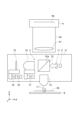
- an interference observation device 1A shown in FIG. 22 differs from the interference observation device 1 in that it further includes a surface AF (Autofocus) unit 6.
- the surface AF unit 6 includes an AF light source 61 that outputs light L6, and a beam splitter 62, which is, for example, a dichroic mirror. Note that a half mirror that does not have wavelength selectivity may be used as the beam splitter 62, although this may reduce the efficiency of light utilization.
- the beam splitter 62 splits the light L6 into two, and outputs one of the two split lights L6 to the interference optical system 3.
- the light L6 output to the interference optical system 3 is reflected by the surface (outer surface) of the observation object 8, and returns to the surface AF unit 6 via the interference optical system 3 and the beam splitter 62.
- the surface AF unit 6 detects the light L6, which is the return light from the observation object 8, and adjusts the relative distance between the objective lens 13 and the surface of the observation object 8 based on the detection result. For example, the surface AF unit 6 maintains a predetermined distance between the objective lens 13 and the observation object 8 by moving the objective lens 13 along the Z direction using the actuator 16.
- the surface AF unit 6 acquires the light L6 output from the AF light source 61 and reflected by the surface of the observation object 8 via the interference optical system 3, and adjusts the relative position between the objective lens 13 and the surface of the observation object 8 based on the acquired result.
- the interference observation device 1A is provided with a filter 63 that is disposed between the beam splitter 12 and the reference objective lens 14 and blocks the light L6 reflected by the beam splitter 12.
- the optical path length of the second light L2 can be adjusted based on an evaluation value common to the focus adjustment, simultaneously with the focus adjustment (steps S6 and S14). This point will be explained below.
- Fig. 23(a) shows a case where the focus position of the objective lens 13 is located on the surface of the observation object 8 with a refractive index n1 and a thickness d0 (broken line) and the distance between the objective lens 13 and the observation object 8 is shortened by ⁇ d0 as shown by the solid line, and the focus position is changed to the back surface (solid line).
- Fig. 23(a) shows a case where the focus position of the objective lens 13 is located on the surface of the observation object 8 with a refractive index n1 and a thickness d0 (broken line) and the distance between the objective lens 13 and the observation object 8 is shortened by ⁇ d0 as shown by the solid line, and the focus position is changed to the back surface (solid line).
- FIG. 23(b) shows a case where the focus position of the objective lens 13 is located on the surface of the observation object 8 with a refractive index n1 and a thickness d1 (broken line) and the distance between the objective lens 13 and the observation object 8 is shortened by ⁇ d1 as shown by the solid line, and the focus position is changed to the back surface (solid line).
- FIG. 23C shows a state after the distance between the objective lens 13 and the observation object 8 has been adjusted by the front-surface AF unit 6 from the state shown in FIG. 23B.
- the correction amount of the optical path length of the second light L2 is expressed by the following (4), where WD is the working distance of the objective lens 13 in air.
- both the focus position of the objective lens 13 and the optical path length of the second light L2 are considered to be targets for optical adjustment.
- the adjustment amount ⁇ z of the focus position of the objective lens 13 is expressed by equation (6) with the direction in which the objective lens 13 approaches the observed object 8 being positive.
- the optical path length of the second light L2 may also be adjusted so that the ratio of the adjustment amount of the optical path length of the second light L2 to the adjustment amount of the focus position of the objective lens 13 (the distance between the objective lens 13 and the observation object 8) becomes n 1 2 ⁇ 1 : 1.
- the optical path length of the second light L2 can be adjusted based on an evaluation value common to the focus adjustment at the same time as the focus adjustment.
- the adjustment of the optical path length of the second light L2 may be performed based on an evaluation value other than the focus adjustment.
- the processing unit 5 calculates the curvature amount of the interference fringes in the phase image Arg(Comp) as the first evaluation value or the second evaluation value, and adjusts the focus of the objective lens 13 based on the first evaluation value and the second evaluation value. That is, in this case, the processing unit 5 calculates the curvature amount of the interference fringes in the phase image as the first evaluation value or the second evaluation value in step S24. A method of calculating the curvature amount of the interference fringes based on the phase image will be described later.
- the other processing is the same as in the above-mentioned processing. This makes it possible to adjust the optical path length of the second light L2 and adjust the focus of the objective lens 13.
- the adjustment of the optical path length of the second light L2 may be performed before or after the focus adjustment, or may be performed in parallel with the focus adjustment.
- a linear sum or vector sum of the difference in the amplitude of the interference fringes and the difference in the curvature amount may be adopted as a new evaluation function.
- This new evaluation function g(a, b) of the interference fringes is a two-variable function expressed by both the optical path length a and the focus shift amount b of the first light L1 (object light) and the second light L2 (reference light).
- the differentiation of the evaluation value when only the optical path length of the reference optical path (the optical path length of the second light L2) is moved is described as the partial differentiation ⁇ g/ ⁇ a of g(a, b) with respect to a
- the differentiation of the evaluation value when only the focus of the reference optical path is moved is described as the partial differentiation ⁇ g/ ⁇ b of g(a, b) with respect to b (Equation (8)).
- the gradient vector of the evaluation value is described as a two-dimensional vector with ⁇ g/ ⁇ a as the first element and ⁇ g/ ⁇ b as the second element.
- the steepest descent method or the conjugate gradient method can be used as a method for optimizing the parameters a and b toward the maximum value of the evaluation function, so that the adjustment of the optical path length of the second light L2 and the adjustment of the focus of the objective lens 13 may be performed simultaneously or at an interval based on the adjustment values obtained by these optimization methods.
- the effect contributes to the evaluation function g(a, b) in terms of both changes in the light path length and changes in focus.
- the light path length of the second light L2 and the focus of the objective lens 13 can be adjusted based on the fact that it is the light path length that mainly contributes to the amplitude of the interference fringes, and the amount of curvature that mainly contributes to the curvature of the interference fringes.
- a method for calculating the curvature of the interference fringes based on a phase image will be described with reference to FIG. 24.
- a method based on correlation with a test image having an estimated curvature is conceivable.
- the above-mentioned Reference 2 describes a method for calculating Zernike polynomial components of a wavefront from a phase image.
- the curvature of the interference fringes can be associated with the following component (9) known as "Defocus" in the Zernike polynomial.
- the amount of curvature of the interference fringes can be calculated based on the phase image by comparing the acquired phase image with test images having amounts of curvature such as +5.0, +10.0, and +20.0. Note that the method of calculating the amount of curvature from the interference fringes is not limited to this method.
- the reference mirror 15 is moved between the front position and the rear position by the piezoelectric element 19 (steps S1 and S9), but the reference mirror 15 may be moved between the front position and the rear position by the stepping motor 18 in steps S1 and S9.
- the stepping motor 18 may be configured to be driven in a fine movement mode (first mode) and a coarse movement mode (second mode).
- the fine movement mode the step angle (movement distance) of the stepping motor 18 is smaller than that in the coarse movement mode, microstep driving is possible, the pulse rate is high, and there is no limit check.
- the processing unit 5 drives the stepping motor 18 in the first mode to move the reference mirror 15 between the front position and the rear position, and acquires the first interference image and the second interference image (steps S3 and S11).
- the processing unit 5 moves the reference mirror 15 by driving the stepping motor 18 in the second mode.
- This processing can also perform optical adjustment similar to the above-mentioned processing.
- the piezoelectric element 19 may be omitted. This processing is particularly effective when using a spatial fringe method that does not require the movement of the reference mirror 15 by the piezoelectric element 19. [Application example of optical adjustment processing]
- the initial adjustment of the interference observation device 1 there is the initial adjustment of the interference observation device 1.
- the initial adjustment may be applied to either surface observation or internal observation, and adjusts the focus position of the objective lens 13 and the optical path length of the second light L2. Since there is a possibility that micron-scale displacements may occur in the housing H of the optical module M due to temperature changes and aging, it is considered that the initial adjustment is performed periodically (for example, about once a week).
- " ⁇ " is shown when adjustment is performed using the optical adjustment method based on the first and second interference images described above, “separately” is shown when adjustment is performed using a method other than the optical adjustment method, and "-" is shown when no adjustment is performed.
- the focus position of the objective lens 13 is adjusted to the observation target surface R.
- This focus adjustment can be performed using an adjustment method such as contrast AF.
- Contrast AF is a method in which the focus position is scanned over the entire optical axis direction of the observation target 8 to obtain multiple interference images, and the point at which the evaluation function of the contrast of the interference images is maximized is adopted as the focus position.
- the processing unit 5 performs an optical adjustment process to adjust the optical path length (reference optical path length) of the second light L2 using the average value in the image of the amplitude image as the first evaluation value or the second evaluation value.
- the processing unit 5 adjusts the distance (reference side focus) between the reference objective lens 14 and the reference mirror 15 using the curvature amount of the interference fringes in the phase image as the first evaluation value or the second evaluation value. More specifically, in this case, the stepping motors 17 and 18 are controlled so that the distance between the reference objective lens 14 and the reference mirror 15 becomes the target distance. Either the adjustment of the optical path length of the second light L2 or the adjustment of the reference side focus may be performed first. During initial adjustment, stage S does not move along the XY plane.
- FIG. 26 surface observation as shown in FIG. 26 can be considered.
- the focus position of the objective lens 13 can be adjusted by the above-mentioned process (FIG. 5).
- the focus position is adjusted while the stage S moves along the XY plane.
- the calculation of the first evaluation value and the second evaluation value and the adjustment of the focus position may be performed in a culled manner.
- the calculation of the first evaluation value and the second evaluation value and the adjustment of the focus position are performed every three times the observation position (field of view) is changed (in this example, this is performed only for fields of view #3, #6, #9, etc.).
- the stage S may be driven at a constant speed instead of the method of repeatedly moving and stopping each time an image is captured (Stop and Go) as in the above example. That is, in the above example, focus adjustment is performed each time the stage S moves once, but focus adjustment may be performed each time the stage S moves a predetermined number of times as in the example shown in FIG. 27, or focus adjustment may be performed while the stage S moves continuously as in this example. In either case, the processing unit 5 performs optical adjustment processing based on the first interference image and the second interference image according to the movement of the stage S along the XY plane.
- the above-mentioned initial adjustment process and surface observation process may be used in a hybrid manner.
- the initial adjustment process may be performed in the first field of view in each row (field of view #1, #7, #15, ).
- contrast AF takes time, when it is performed intermittently as in this example, the impact on the takt time can be suppressed.
- the focus position of the objective lens 13 may be adjusted based on the first interference image and the second interference image according to the surface observation process.
- the field of view in which the initial adjustment process is performed may be selected as the field of view where contrast AF is easy to perform, such as the edge of the observed object 8.
- the process of performing optical adjustment processing based on the first interference image and the second interference image is a fine adjustment process
- the process of adjusting the focus position of the objective lens 13 by contrast AF is a focus position adjustment process
- the fine adjustment process or the focus position adjustment process is performed according to the observation position of the observed object 8 along the XY plane.
- the focus position adjustment process (contrast AF)
- the direction in which the first light L1 is incident on the observed object 8 is defined as the incident direction
- multiple interference images are acquired while the focal position of the objective lens 13 is scanned over the entire observed object 8 in the incident direction, and the focal position is adjusted based on the acquisition results.
- internal observation can be considered as a third application example.
- both the focus position of the objective lens 13 and the optical path length of the second light L2 are adjusted.
- the focus position of the objective lens 13 and the optical path length of the second light L2 may be adjusted based on a common evaluation value using the interference observation device 1A equipped with the surface AF unit 6.
- the average value in the image of the amplitude image may be used as the first evaluation value or the second evaluation value to perform an optical adjustment process for adjusting the optical path length of the second light L2
- the curvature amount of the interference fringes in the phase image may be used as the first evaluation value or the second evaluation value to perform an optical adjustment process for adjusting the focus position of the objective lens 13.
- Both the optical adjustment process for adjusting the optical path length of the second light L2 and the optical adjustment process for adjusting the focus position of the objective lens 13 may be performed each time the field of view is moved (the observation position is changed). Alternatively, they may be thinned out so that only one is performed in odd-numbered fields of view and only the other is performed in even-numbered fields of view.
- Examples of internal observation include, in addition to the above-mentioned example in which the observation object 8 is a semiconductor device with a cap, observing a semiconductor device through a transparent resin cap, observing a semiconductor device through a glass window, observing a semiconductor device through a semiconductor cap (in this case, the light source 2 outputs infrared light), observing the back side of a semiconductor device (in this case, the light source 2 outputs infrared light), observing the bonding surface of a bonded wafer (in this case, the light source 2 outputs infrared light), observing voids on the bonding surface of a bonded wafer, observing the joint or bonding surface between glass and resin, observing the laser-processed surface inside a member made of glass, resin, or semiconductor, observing internal defects in a liquid crystal panel, etc.
- adjustments when replacing the objective lens 13 can be considered.
- the objective lens 13 is replaceably attached to the housing H, and one objective lens 13 selected from a plurality of objective lenses 13 (three in this example) with different magnifications is attached to the housing H.
- optical adjustments can be made quickly and accurately by performing optical adjustments based on the first interference image and second interference image described above.
- step S71 the objective lens 13 is replaced (step S71).
- step S72 the focus position of the objective lens 13 is adjusted to the observation target surface R.
- This focus adjustment can be performed using an adjustment method such as contrast AF (step S72).
- the processing unit 5 controls the stepping motors 17 and 18 to adjust the optical path length of the second light L2 by the nominal offset of the objective lens 13 (step S73) (coarse adjustment).
- step S73 the processing unit 5 performs an optical adjustment process to adjust the optical path length of the second light L2 using the intra-image average value of the amplitude image as the first evaluation value or the second evaluation value (fine adjustment).
- the nominal offset of the objective lens 13 is the value of the optical path length of the second light L2 that needs to be corrected according to the difference in optical path length for each objective lens 13, and is measured in advance.
- micron-scale errors can occur due to the influence of aging of the objective lens, temperature environment, and mechanical errors at the attachment point of the objective lens, it is possible that optimal interference fringes cannot be obtained by simply adjusting the nominal offset. If an adapter is attached to the objective lens 13, the nominal offset is set taking into account the contribution of the adapter.
- an adapter 13a may be attached to at least one of the objective lenses 13.
- the objective lens 13 in addition to changing the magnification, it is also possible to change from a dry objective lens to an immersion objective lens (water immersion, etc.).
- the resolution of interference observation is determined by the NA of the objective lens 13 or the reference objective lens 14, whichever has the smaller NA. Therefore, it is preferable to match the magnification of the objective lens 14 with the highest NA among the objective lenses 13. For example, if the objective lenses 13 have magnifications of 20X, 10X, and 5X, respectively, the magnification of the objective lens 13 with the highest NA is 20X, so the magnification of the reference objective lens 14 is preferably 20X.
- the immersion objective lens generally has a higher NA even at the same magnification.
- the objective lenses 13 may be fitted with adapters 13a corresponding to the magnification.
- the adapter 13a may be a hollow member for lengthening the optical path length, or a member with a transparent dielectric plate disposed inside.
- the optical path length within the lens is long in the order of 5X ⁇ 10X ⁇ 20X, so by setting the optical path length of the adapter 13a in the opposite order of 5X > 10X > 20X, the travel distance of the stepping motors 17 and 18 during adjustment when replacing the objective lens 13 can be shortened.
- the adapter 13a is mechanically connected or bonded to the objective lens 13 and can be removed and attached as a unit when replacing the objective lens 13.
- the conjugate plane 4b of the image sensor 4's image pickup surface 4a may be shifted from the focus position of the objective lens 13. This shift is usually on the order of a few microns, but is a size that cannot be ignored in interference observation. Even in such a case, the conjugate plane 4b of the image pickup surface 4a can be aligned with the focus position of the objective lens 13 by the optical adjustment process based on the above-mentioned first interference image and second interference image.
- the process when adjusting the lens barrel mechanical difference is the same as that of the initial adjustment.
- the conjugate plane 4b of the image pickup surface 4a is shifted when adjusting the lens barrel mechanical difference, it is more efficient to move only the reference mirror 15 by the stepping motor 18 while keeping the position of the reference objective lens 14 fixed.
- the interference observation device 1 includes a light source 2 that outputs light, an interference optical system 3 that has a movable reference mirror 15, divides the light output from the light source 2 into a first light L1 and a second light L2, and outputs an interference light L3 between the first light L1 reflected by the observation object 8 and the second light L2 reflected by the reference mirror 15, an image sensor 4 that detects the interference light L3, and a processing unit 5 that acquires an interference image based on the detection result of the interference light L3 and performs an optical adjustment process for optical adjustment related to the observation of the observation object 8.
- the processing unit 5 acquires a first interference image and a second interference image in which the optical path length difference between the first light L1 and the second light L2 is different by changing the optical path length of the second light L2, and performs an optical adjustment process based on the first interference image and the second interference image.
- optical adjustment processing is performed based on the first interference image and the second interference image having different optical path length differences obtained by changing the optical path length of the second light L2, so optical adjustment can be performed quickly and accurately.
- optical adjustment can be performed quickly and accurately compared to, for example, scanning the focal position of the objective lens 13 over the entire thickness direction of the observation object 8. For example, when the observation object 8 is scanned over the Z direction for contrast AF, a large amount of noise remains in the detection result for several hundred msec. Therefore, it is difficult to increase the speed, and it is not suitable for in-line measurement, for example.
- the interference observation device 1 can perform optical adjustment quickly and accurately, making it suitable for in-line measurement.
- the processing unit 5 calculates evaluation values (first evaluation value and second evaluation value) for each of the first interference image and the second interference image (steps S4 and S12), and performs optical adjustment processing based on the evaluation values of the first interference image and the second interference image. This allows the optical adjustment processing to be performed optimally.
- the processing unit 5 performs optical adjustment processing based on the difference between the first evaluation value, which is an evaluation value calculated based on the first interference image, and the second evaluation value, which is an evaluation value calculated based on the second interference image (steps S5 and S12). This allows the optical adjustment processing to be performed optimally.
- the processing unit 5 After acquiring the second interference image, the processing unit 5 performs optical adjustment if the absolute value of the difference is greater than a predetermined value, and does not perform optical adjustment if the absolute value of the difference is equal to or less than the predetermined value (steps S5 and S12). This allows the optical adjustment process to be performed optimally.
- the optical adjustment is performed according to the magnitude relationship between the first evaluation value and the second evaluation value (steps S31 to S33). This allows the optical adjustment process to be performed optimally.
- the optical adjustment is performed by an amount corresponding to the magnitude of the difference between the first evaluation value and the second evaluation value (steps S32 and S33). This allows the optical adjustment process to be performed optimally.
- the processing unit 5 calculates the first evaluation value or the second evaluation value based on the amplitude image corresponding to the first interference image or the second interference image (step S24). This makes it possible to preferably calculate the evaluation value.
- the processing unit 5 may calculate an evaluation value for the amount of curvature of the interference fringes in the phase image corresponding to the first interference image or the second interference image (FIG. 24). In this case as well, the evaluation value can be calculated suitably.
- the processing unit 5 moves the reference mirror 15 to change the optical path length of the second light L2, thereby acquiring a first interference image and a second interference image having different optical path length differences. This makes it possible to suitably acquire the first interference image and the second interference image.
- the change in the optical path length of the second light L2 differs by a value greater than the wavelength of the light output from the light source 2. This allows the optical adjustment process to be performed optimally.
- the optical adjustments performed in the interference observation device 1 include adjusting the relative position between the objective lens 13 and the observation object 8. This makes it possible to adjust the relative position between the objective lens 13 and the observation object 8.
- the optical adjustment includes adjusting the optical path length of the second light L2 by moving the reference mirror 15. This makes it possible to adjust the optical path length of the second light L2.
- the optical adjustment includes adjusting the position of the reference objective lens 14. This allows the position of the reference objective lens 14 to be adjusted.
- the observation position for the observation object 8 along the XY plane (a plane intersecting the direction in which the first light L1 is incident on the observation object 8) may be the same (FIG. 21).
- optical adjustment processing can be performed based on the first interference image and the second interference image acquired at the same observation position.
- the observation position along the XY plane with respect to the observation object 8 may be different ( Figure 5).
- optical adjustment processing can be performed based on the first interference image and the second interference image acquired at the different observation positions.
- the processing unit 5 performs optical adjustment processing based on the first interference image and the second interference image in accordance with the movement of the stage S along the XY plane. This makes it possible to move the object of observation 8 and change the observation position while performing optical adjustment.
- the processing unit 5 performs optical adjustment processing to adjust the relative position between the objective lens 13 and the object of observation 8 based on the first interference image and the second interference image in accordance with the movement of the stage S along the XY plane. This makes it possible to change the observation position by moving the object of observation 8 while adjusting the relative position between the objective lens 13 and the object of observation 8.
- the processing unit 5 alternately executes the first process (steps S1 to S8) and the second process (steps S9 to S16).
- the processing unit 5 acquires a first interference image (step S2), performs optical adjustment processing based on the first interference image and the second interference image acquired in the immediately preceding second process (steps S5, S6), and moves the stage S along the plane (step S7).
- the processing unit 5 acquires a second interference image (step S10), performs optical adjustment processing based on the second interference image and the first interference image acquired in the immediately preceding first process (steps S13, S14), and moves the stage S along the plane (step S15). This allows the optical adjustment processing to be performed by sequential processing.
- the processing unit 5 may execute the first process S40, the second process S50, and the third process S60 in parallel.
- the processing unit 5 alternately executes a process of acquiring first data for generating a first interference image from the image sensor 4, storing the first data in a first memory area of the memory area 51 (step S42), and then moving the stage S along the XY plane (step S43), and a process of acquiring second data for generating a second interference image from the image sensor 4, storing the second data in the first memory area (step S45), and then moving the stage S along the XY plane (step S44).
- the processing unit 5 alternately executes a process of generating a first interference image based on the first data acquired in the first process S40 (step S52) and storing a first evaluation value corresponding to the first interference image in the second storage area of the storage area 51 (steps S54, S55) and a process of generating a second interference image based on the second data acquired in the first process S40 (step S52) and storing a second evaluation value corresponding to the second interference image in the second storage area (steps S54, S55).
- the processing unit 5 performs optical adjustment processing based on the first evaluation value and second evaluation value acquired immediately before each time the first evaluation value or the second evaluation value is stored in the second storage area in the second process S50 (step S61).
- the optical adjustment processing can be performed by parallel processing.
- the processing unit 5 uses the piezoelectric element 19 to move the reference mirror 15 to change the optical path length of the second light L2, thereby acquiring a first interference image and a second interference image having different optical path length differences, and performs optical adjustment using the stepping motors 17, 18. This allows optical adjustment processing to be performed using the piezoelectric element 19 and the stepping motors 17, 18. Since the piezoelectric element 19 has a longer lifespan than the stepping motor 18, acquiring the first interference image and the second interference image using the piezoelectric element 19 can extend the lifespan of the device.
- the stepping motor 18 may be capable of being driven in a fine movement mode (first mode) and a coarse movement mode (second mode) having a larger step angle than the fine movement mode.
- the processing unit 5 may drive the stepping motor 18 in the fine movement mode to move the reference mirror 15 and change the optical path length of the second light L2, thereby acquiring a first interference image and a second interference image having different optical path length differences, and may perform optical adjustment by driving the stepping motor 18 in the coarse movement mode.
- the optical adjustment process can be performed using the stepping motor 18, and the configuration of the device can be simplified.
- the stepping motors 17 and 18 used in the optical adjustment process may be other types of motors with a resolution of 1 micrometer to several micrometers.
- Examples of other types of motors include geared motors and servo motors with a large reduction ratio.
- the interference observation device 1A is equipped with a surface AF unit 6.
- the surface AF unit 6 has an AF light source 61 that outputs light L6, acquires the light L6 output from the AF light source 61 and reflected by the surface of the observation object 8 via the interference optical system 3, and adjusts the relative position between the objective lens 13 of the interference optical system 3 and the surface of the observation object 8 based on the acquisition result. In this case, the relative position between the objective lens 13 and the surface of the observation object 8 can be adjusted by the surface AF unit 6.
- the processing unit 5 may perform an optical adjustment process for adjusting the relative position between the objective lens 13 and the observation object 8 based on the first interference image and the second interference image in accordance with the movement of the stage S along the XY plane, and an optical adjustment process for adjusting the optical path length of the second light L2 by moving the reference mirror 15. This makes it possible to perform an optical adjustment process for adjusting the relative position between the objective lens 13 and the observation object 8, and an optical adjustment process for adjusting the optical path length of the second light L2 while moving the observation object 8.
- a first interference image and a second interference image may be acquired based on the detection result of the interference light between the first light L1 reflected by the surface of the observation object 8 and the second light L2 reflected by the reference mirror 15 (surface observation). This allows optical adjustment to be performed in the case of surface observation in which the surface of the observation object 8 is observed.
- a first interference image and a second interference image may be obtained based on the detection result of the interference light between the first light L1 reflected inside the observation object 8 and the second light L2 reflected by the reference mirror 15 (internal observation). This makes it possible to perform optical adjustment in the case of internal observation, in which the inside of the observation object 8 is observed.
- optical adjustment processing may be performed based on the first interference image and the second interference image in response to the movement of the observed object 8 along the XY plane.
- the optical adjustment processing can be performed while the observed object 8 is being moved.
- an optical adjustment process may be performed to adjust the optical path length of the second light L2 by moving the reference mirror 15 based on the first interference image and the second interference image (adjustment when the objective lens 13 is replaced). In this way, when the objective lens 13 is replaced, optical adjustment can be performed.
- the present disclosure is not limited to the above-mentioned examples.
- the materials and shapes of each component are not limited to those described above, and various materials and shapes can be used.
- the first and second interference images were obtained by moving the reference mirror 15 to change the optical path length of the second light L2, but the first and second interference images may also be obtained by moving the objective lens 13 to change the optical path length of the second light L2.
- the optical adjustment process was performed based on two interference images, the first and second interference images, but the optical adjustment process may also be performed based on three or more interference images.
- the evaluation value based on the amplitude image (first evaluation value or second evaluation value) is not limited to the average value within the amplitude image, and may be another value calculated based on the amplitude image.
- the evaluation value based on the phase image is not limited to the amount of curvature of the interference fringes in the phase image, and may be another value calculated based on the phase image.
- the evaluation value may be calculated based on both the amplitude image and the phase image.
- the optical path length of the second light L2 may differ by a value smaller than the wavelength of the light output from the light source 2. In this case, the optical adjustment process can be performed in the same way as in the above example.
- the relative position between the objective lens 13 and the object of observation 8 is adjusted by moving the objective lens 13 along the Z direction by the actuator 16.
- the relative position may be adjusted by moving the stage S along the Z direction.
- the stage S is configured to be movable in the Z direction in addition to the XY directions.
- the actuator 16 may be omitted.
- the stage S may be movable along a direction intersecting the direction in which the first light L1 is incident on the object of observation 8, and may be movable in a direction inclined with respect to the XY plane, for example.
- the actuators that drive the reference objective lens 14 and the reference mirror 15 are not limited to the stepping motors 17 and 18, and may be other actuators such as servo motors.
- the interference images may be spatially thinned (reduced in resolution) before image processing in a subroutine specialized for determining the evaluation value.
- the interference image used as the inspection image may be generated using a separate high-resolution image, and the evaluation value may be calculated from the thinned image, thereby speeding up image processing.
- the interference optical system 3 is configured as a Linnik interference type, but the interference optical system 3 (interference observation device 1) may be configured as a Michelson interference type or a Mirau interference type.
- the reference objective lens 14 may be omitted.
- 1, 1A... interference observation device 2... light source, 3... interference optical system, 4... imaging element, 5... processing unit, 6... surface AF unit, 61... AF light source, 8... observation object, 13... objective lens, 14... reference objective lens, 15... reference mirror, 18... stepping motor, 19... piezoelectric element, 51... storage area, L1... first light, L2... second light, L3... interference light, L6... light, S... stage, S40... first processing, S50... second processing, S60... third processing.
Landscapes
- Physics & Mathematics (AREA)
- General Physics & Mathematics (AREA)
- Optics & Photonics (AREA)
- Chemical & Material Sciences (AREA)
- Analytical Chemistry (AREA)
- Engineering & Computer Science (AREA)
- Multimedia (AREA)
- Microscoopes, Condenser (AREA)
- Instruments For Measurement Of Length By Optical Means (AREA)
- Automatic Focus Adjustment (AREA)
- Mechanical Light Control Or Optical Switches (AREA)
Abstract
Description
[干渉観察装置]
[干渉観察装置の動作例]
[別の動作例]
[光学調整処理の適用例]
[作用及び効果]
[変形例]
Claims (29)
- 光を出力する光源と、
移動可能な参照ミラーを有し、前記光源から出力された光を第1光及び第2光に分割し、観察対象物で反射された前記第1光と前記参照ミラーで反射された前記第2光との干渉光を出力する干渉光学系と、
前記干渉光を検出する撮像素子と、
前記干渉光の検出結果に基づいて干渉画像を取得すると共に、前記観察対象物の観察に関連する光学調整のための光学調整処理を行う処理部と、を備え、
前記処理部は、前記第2光の光路長を変化させることにより前記第1光と前記第2光との間の光路長差が異なる複数の干渉画像を取得し、前記複数の干渉画像に基づいて前記光学調整処理を行う、干渉観察装置。 - 前記処理部は、前記複数の干渉画像の各々について評価値を算出し、前記複数の干渉画像の前記評価値に基づいて前記光学調整処理を行う、請求項1に記載の干渉観察装置。
- 前記複数の干渉画像は、前記光路長差が互いに異なる第1干渉画像及び第2干渉画像を含み、
前記処理部は、前記第1干渉画像に基づいて算出された前記評価値である第1評価値と、前記第2干渉画像に基づいて算出された前記評価値である第2評価値との間の差分に基づいて前記光学調整処理を行う、請求項2に記載の干渉観察装置。 - 前記第1干渉画像が取得された後に前記第2干渉画像が取得され、
前記処理部は、前記第2干渉画像の取得後に、前記差分の絶対値が所定値よりも大きい場合には前記光学調整を行い、前記差分の絶対値が所定値以下である場合には前記光学調整を行わない、請求項3に記載の干渉観察装置。 - 前記処理部は、前記第2干渉画像の取得後に前記光学調整を行う場合に、前記第1評価値と前記第2評価値との間の大小関係に応じて前記光学調整を行う、請求項4に記載の干渉観察装置。
- 前記処理部は、前記第2干渉画像の取得後に前記光学調整を行う場合に、前記第1評価値と前記第2評価値との間の前記差分の大きさに対応する量で前記光学調整を行う、請求項4又は5に記載の干渉観察装置。
- 前記処理部は、前記干渉画像に対応する振幅画像に少なくとも基づいて前記評価値を算出する、請求項2~6のいずれか一項に記載の干渉観察装置。
- 前記処理部は、前記干渉画像に対応する位相画像における干渉縞の湾曲量に少なくとも基づいて前記評価値を算出する、請求項2~7のいずれか一項に記載の干渉観察装置。
- 前記処理部は、前記参照ミラーを移動させて前記第2光の光路長を変化させることにより、前記光路長差が異なる前記複数の干渉画像を取得する、請求項1~8のいずれか一項に記載の干渉観察装置。
- 前記複数の干渉画像の間において、前記第2光の光路長の変化量は、前記光源から出力される光の波長よりも大きい値だけ異なる、請求項1~9のいずれか一項に記載の干渉観察装置。
- 前記干渉光学系は、対物レンズを更に有し、
前記光学調整は、前記対物レンズと前記観察対象物との間の相対位置を調整することを含む、請求項1~10のいずれか一項に記載の干渉観察装置。 - 前記光学調整は、前記参照ミラーを移動させて前記第2光の前記光路長を調整することを含む、請求項1~11のいずれか一項に記載の干渉観察装置。
- 前記干渉光学系は、前記第2光を前記参照ミラーへ導光する参照対物レンズを更に有し、
前記光学調整は、前記参照対物レンズの位置を調整することを含む、請求項1~12のいずれか一項に記載の干渉観察装置。 - 前記複数の干渉画像の間において、前記観察対象物に前記第1光が入射する方向と交差する平面に沿っての前記観察対象物に対する観察位置は、同一である、請求項1~13のいずれか一項に記載の干渉観察装置。
- 前記複数の干渉画像の間において、前記観察対象物に前記第1光が入射する方向と交差する平面に沿っての前記観察対象物に対する観察位置は、異なっている、請求項1~13のいずれか一項に記載の干渉観察装置。
- 前記観察対象物を配置するためのステージであって、前記観察対象物に前記第1光が入射する方向と交差する平面に沿って少なくとも移動可能な前記ステージを更に備え、
前記処理部は、前記ステージの前記平面に沿っての移動に応じて、前記複数の干渉画像に基づいて前記光学調整処理を行う、請求項1~15のいずれか一項に記載の干渉観察装置。 - 前記干渉光学系は、対物レンズを更に有し、
前記処理部は、前記ステージの前記平面に沿っての移動に応じて、前記複数の干渉画像に基づいて、前記対物レンズと前記観察対象物との間の相対位置を調整するための前記光学調整処理を行う、請求項16に記載の干渉観察装置。 - 前記観察対象物を配置するためのステージであって、前記観察対象物に前記第1光が入射する方向と交差する平面に沿って少なくとも移動可能な前記ステージを更に備え、
前記複数の干渉画像は、前記光路長差が互いに異なる第1干渉画像及び第2干渉画像を含み、
前記処理部は、第1処理及び第2処理を交互に実行する、
ここで、前記第1処理では、前記処理部は、前記第1干渉画像を取得し、前記第1干渉画像と、直前の前記第2処理において取得された前記第2干渉画像とに基づいて前記光学調整処理を行うと共に、前記ステージを前記平面に沿って移動させ、
前記第2処理では、前記処理部は、前記第2干渉画像を取得し、前記第2干渉画像と、直前の前記第1処理において取得された前記第1干渉画像とに基づいて前記光学調整処理を行うと共に、前記ステージを前記平面に沿って移動させる、請求項1~17のいずれか一項に記載の干渉観察装置。 - 前記観察対象物を配置するためのステージであって、前記観察対象物に前記第1光が入射する方向と交差する平面に沿って少なくとも移動可能な前記ステージと、
第1記憶領域及び第2記憶領域と、を更に備え、
前記複数の干渉画像は、前記光路長差が互いに異なる第1干渉画像及び第2干渉画像を含み、
前記処理部は、第1処理、第2処理及び第3処理を並列に実行する、
ここで、前記第1処理では、前記処理部は、前記第1干渉画像を生成するための第1データを前記撮像素子から取得し、前記第1記憶領域に前記第1データを記憶させた後に、前記ステージを前記平面に沿って移動させる処理と、前記第2干渉画像を生成するための第2データを前記撮像素子から取得し、前記第1記憶領域に前記第2データを記憶させた後に、前記ステージを前記平面に沿って移動させる処理と、を交互に実行し、
前記第2処理では、前記処理部は、前記第1処理において取得された前記第1データに基づいて前記第1干渉画像を生成し、前記第1干渉画像に対応する第1評価値を前記第2記憶領域に記憶させる処理と、前記第1処理において取得された前記第2データに基づいて前記第2干渉画像を生成し、前記第2干渉画像に対応する第2評価値を前記第2記憶領域に記憶させる処理と、を交互に実行し、
前記第3処理では、前記処理部は、前記第2処理において前記第1評価値又は前記第2評価値が前記第2記憶領域に記憶される度に、直前に取得された前記第1評価値及び前記第2評価値に基づいて前記光学調整処理を行う、請求項1~17のいずれか一項に記載の干渉観察装置。 - 前記参照ミラーを移動させるためのピエゾ素子と、
前記光学調整の対象を移動させるためのモータと、を更に備え、
前記処理部は、前記ピエゾ素子を用いて参照ミラーを移動させて前記第2光の光路長を変化させることにより、前記光路長差が異なる前記複数の干渉画像を取得すると共に、前記モータを用いて前記光学調整を行う、請求項1~19のいずれか一項に記載の干渉観察装置。 - 前記参照ミラーを移動させるためのステッピングモータを更に備え、
前記ステッピングモータは、第1モードと、前記第1モードよりもステップ角が大きな第2モードで駆動可能であり、
前記処理部は、前記ステッピングモータを前記第1モードで駆動させることによって参照ミラーを移動させて前記第2光の光路長を変化させることにより、前記光路長差が異なる前記複数の干渉画像を取得すると共に、前記ステッピングモータを前記第2モードで駆動させることによって前記光学調整を行う、請求項1~19のいずれか一項に記載の干渉観察装置。 - 前記干渉光学系は、対物レンズを更に有し、
前記干渉観察装置は、光を出力するAF光源を有し、前記AF光源から出力されて前記観察対象物の表面で反射された光を前記干渉光学系を介して取得し、取得結果に基づいて前記干渉光学系の対物レンズと前記観察対象物の前記表面との間の相対位置を調整する表面AF部を更に備える、請求項1~21のいずれか一項に記載の干渉観察装置。 - 前記観察対象物を配置するためのステージであって、前記観察対象物に前記第1光が入射する方向と交差する平面に沿って少なくとも移動可能な前記ステージを更に備え、
前記処理部は、前記ステージの前記平面に沿っての移動に応じて、前記複数の干渉画像に基づいて、前記対物レンズと前記観察対象物との間の相対位置を調整するための前記光学調整処理、及び前記参照ミラーを移動させて前記第2光の前記光路長を調整するための前記光学調整処理を行う、請求項22に記載の干渉観察装置。 - 光を出力する光源と、移動可能な参照ミラーを有し、前記光源から出力された光を第1光及び第2光に分割し、観察対象物で反射された前記第1光と前記参照ミラーで反射された前記第2光との干渉光を出力する干渉光学系と、前記干渉光を検出する撮像素子と、を備え、前記干渉光の検出結果に基づいて干渉画像が取得される干渉観察装置において、前記観察対象物の観察に関連する光学調整を行うための光学調整方法であって、
前記第2光の光路長を変化させることにより前記第1光と前記第2光との間の光路長差が異なる複数の干渉画像を取得し、前記複数の干渉画像に基づいて前記光学調整のための光学調整処理を行う工程を含む、光学調整方法。 - 前記工程では、前記観察対象物の表面で反射された前記第1光と前記参照ミラーで反射された前記第2光との前記干渉光の検出結果に基づいて、前記複数の干渉画像を取得する、請求項24に記載の光学調整方法。
- 前記工程では、前記観察対象物の内部で反射された前記第1光と前記参照ミラーで反射された前記第2光との前記干渉光の検出結果に基づいて、前記複数の干渉画像を取得する、請求項24に記載の光学調整方法。
- 前記工程では、前記観察対象物に前記第1光が入射する方向と交差する平面に沿って前記観察対象物を移動させることにより、前記平面に沿っての前記観察対象物に対する観察位置を変化させ、前記平面に沿っての前記観察対象物の移動に応じて、前記複数の干渉画像に基づいて前記光学調整処理を行う、請求項24~26のいずれか一項に記載の光学調整方法。
- 前記干渉光学系は、交換可能な対物レンズを更に有し、
前記工程では、前記対物レンズが交換された場合に、前記複数の干渉画像に基づいて、前記参照ミラーを移動させて前記第2光の前記光路長を調整するための前記光学調整処理を行う、請求項24~27のいずれか一項に記載の光学調整方法。 - 前記第2光の光路長を変化させることにより前記第1光と前記第2光との間の光路長差が異なる前記複数の干渉画像を取得し、前記複数の干渉画像に基づいて前記光学調整のための光学調整処理を行う前記工程を微調整工程とし、
前記観察対象物に前記第1光が入射する方向を入射方向とし、対物レンズの焦点位置を前記入射方向における前記観察対象物の全体にわたってスキャンしながら複数の干渉画像を取得し、取得結果に基づいて前記焦点位置を調整する工程を焦点位置調整工程とすると、
前記入射方向と交差する平面に沿っての前記観察対象物の移動に伴って、前記平面に沿っての前記観察対象物に対する観察位置に応じて、前記微調整工程又は前記焦点位置調整工程が行われる、請求項24~28のいずれか一項に記載の光学調整方法。
Priority Applications (3)
| Application Number | Priority Date | Filing Date | Title |
|---|---|---|---|
| DE112023006112.2T DE112023006112T5 (de) | 2023-03-31 | 2023-11-29 | Interferenzbeobachtungseinrichtung und optisches einstellungsverfahren |
| CN202380096743.0A CN120936928A (zh) | 2023-03-31 | 2023-11-29 | 干涉观察装置及光学调整方法 |
| KR1020257029561A KR20250164174A (ko) | 2023-03-31 | 2023-11-29 | 간섭 관찰 장치 및 광학 조정 방법 |
Applications Claiming Priority (2)
| Application Number | Priority Date | Filing Date | Title |
|---|---|---|---|
| JP2023057078A JP2024144906A (ja) | 2023-03-31 | 2023-03-31 | 干渉観察装置及び光学調整方法 |
| JP2023-057078 | 2023-03-31 |
Publications (1)
| Publication Number | Publication Date |
|---|---|
| WO2024202243A1 true WO2024202243A1 (ja) | 2024-10-03 |
Family
ID=92903872
Family Applications (1)
| Application Number | Title | Priority Date | Filing Date |
|---|---|---|---|
| PCT/JP2023/042790 Ceased WO2024202243A1 (ja) | 2023-03-31 | 2023-11-29 | 干渉観察装置及び光学調整方法 |
Country Status (6)
| Country | Link |
|---|---|
| JP (1) | JP2024144906A (ja) |
| KR (1) | KR20250164174A (ja) |
| CN (1) | CN120936928A (ja) |
| DE (1) | DE112023006112T5 (ja) |
| TW (1) | TW202509418A (ja) |
| WO (1) | WO2024202243A1 (ja) |
Citations (2)
| Publication number | Priority date | Publication date | Assignee | Title |
|---|---|---|---|---|
| JP2019117490A (ja) * | 2017-12-27 | 2019-07-18 | 浜松ホトニクス株式会社 | 計数装置および計数方法 |
| JP2021129844A (ja) * | 2020-02-20 | 2021-09-09 | キヤノン株式会社 | 撮像装置、学習済モデル、学習済モデル生成装置、作動方法、及びプログラム |
Family Cites Families (1)
| Publication number | Priority date | Publication date | Assignee | Title |
|---|---|---|---|---|
| US10393500B2 (en) | 2015-01-30 | 2019-08-27 | Hamamatsu Photonics K.K. | Interference observation device and interference observation method |
-
2023
- 2023-03-31 JP JP2023057078A patent/JP2024144906A/ja active Pending
- 2023-11-29 CN CN202380096743.0A patent/CN120936928A/zh active Pending
- 2023-11-29 DE DE112023006112.2T patent/DE112023006112T5/de active Pending
- 2023-11-29 KR KR1020257029561A patent/KR20250164174A/ko active Pending
- 2023-11-29 WO PCT/JP2023/042790 patent/WO2024202243A1/ja not_active Ceased
-
2024
- 2024-01-11 TW TW113101200A patent/TW202509418A/zh unknown
Patent Citations (2)
| Publication number | Priority date | Publication date | Assignee | Title |
|---|---|---|---|---|
| JP2019117490A (ja) * | 2017-12-27 | 2019-07-18 | 浜松ホトニクス株式会社 | 計数装置および計数方法 |
| JP2021129844A (ja) * | 2020-02-20 | 2021-09-09 | キヤノン株式会社 | 撮像装置、学習済モデル、学習済モデル生成装置、作動方法、及びプログラム |
Also Published As
| Publication number | Publication date |
|---|---|
| DE112023006112T5 (de) | 2026-04-02 |
| CN120936928A (zh) | 2025-11-11 |
| TW202509418A (zh) | 2025-03-01 |
| JP2024144906A (ja) | 2024-10-15 |
| KR20250164174A (ko) | 2025-11-24 |
Similar Documents
| Publication | Publication Date | Title |
|---|---|---|
| JP6630292B2 (ja) | 干渉観察装置および干渉観察方法 | |
| US8773757B2 (en) | Slit-scan multi-wavelength confocal lens module and slit-scan microscopic system and method using the same | |
| Hemmert et al. | Nanometer resolution of three-dimensional motions using video interference microscopy | |
| WO2013084557A1 (ja) | 形状測定装置 | |
| CN110869696B (zh) | 耐振白色光干涉显微镜及其振动影响去除方法 | |
| JP5266551B2 (ja) | 表面形状測定装置、及び表面形状測定方法 | |
| KR20200125149A (ko) | 실시간으로 자동 초점이 가능한, 측정 대상물의 입체형상을 측정하는 입체형상 측정장치 | |
| CN106872469B (zh) | 一种基于共角干涉的层析相位显微方法与装置 | |
| JP5281837B2 (ja) | 曲率半径測定方法および装置 | |
| CN112729135A (zh) | 一种具有主动光学防抖功能的面阵扫频测距/厚的装置和方法 | |
| CN117491285A (zh) | 基于图像清晰度聚焦的方法及装置 | |
| JP2016148569A (ja) | 画像測定方法、及び画像測定装置 | |
| JP2024144906A (ja) | 干渉観察装置及び光学調整方法 | |
| WO2024202244A1 (ja) | 干渉観察装置、光学調整方法、光学調整プログラム | |
| CN114234835A (zh) | 检测设备和检测方法 | |
| JP5249739B2 (ja) | 観察装置および観察方法 | |
| JP5037432B2 (ja) | 波面測定方法および装置 | |
| JP2010048621A (ja) | 観察装置および観察方法 | |
| JP2011220903A (ja) | 屈折率測定方法および屈折率測定装置 | |
| CN1696604A (zh) | 一种具有环境加载功能的微机电系统动态特性测量装置 | |
| JP2009145068A (ja) | 表面形状の測定方法および干渉計 | |
| KR102509303B1 (ko) | 표면형상 측정장치 및 그 제어방법 | |
| JPH07311117A (ja) | 多眼レンズ位置測定装置 | |
| US20250369744A1 (en) | Microscope including interferometer | |
| KR20250055624A (ko) | 횡방향 스캐닝 백색광 간섭계를 이용한 표면 형상 측정장치 |
Legal Events
| Date | Code | Title | Description |
|---|---|---|---|
| 121 | Ep: the epo has been informed by wipo that ep was designated in this application |
Ref document number: 23930868 Country of ref document: EP Kind code of ref document: A1 |
|
| ENP | Entry into the national phase |
Ref document number: 1020257029561 Country of ref document: KR Free format text: ST27 STATUS EVENT CODE: A-0-1-A10-A15-NAP-PA0105 (AS PROVIDED BY THE NATIONAL OFFICE) |
|
| WWE | Wipo information: entry into national phase |
Ref document number: 112023006112 Country of ref document: DE |
|
| 122 | Ep: pct application non-entry in european phase |
Ref document number: 23930868 Country of ref document: EP Kind code of ref document: A1 |
|
| WWP | Wipo information: published in national office |
Ref document number: 112023006112 Country of ref document: DE |