WO2024202056A1 - 制振装置、露光装置、及び露光方法 - Google Patents
制振装置、露光装置、及び露光方法 Download PDFInfo
- Publication number
- WO2024202056A1 WO2024202056A1 PCT/JP2023/013687 JP2023013687W WO2024202056A1 WO 2024202056 A1 WO2024202056 A1 WO 2024202056A1 JP 2023013687 W JP2023013687 W JP 2023013687W WO 2024202056 A1 WO2024202056 A1 WO 2024202056A1
- Authority
- WO
- WIPO (PCT)
- Prior art keywords
- weight
- leaf spring
- mechanisms
- damping device
- vibration damping
- Prior art date
- Legal status (The legal status is an assumption and is not a legal conclusion. Google has not performed a legal analysis and makes no representation as to the accuracy of the status listed.)
- Ceased
Links
Images

Classifications
-
- G—PHYSICS
- G03—PHOTOGRAPHY; CINEMATOGRAPHY; ANALOGOUS TECHNIQUES USING WAVES OTHER THAN OPTICAL WAVES; ELECTROGRAPHY; HOLOGRAPHY
- G03F—PHOTOMECHANICAL PRODUCTION OF TEXTURED OR PATTERNED SURFACES, e.g. FOR PRINTING, FOR PROCESSING OF SEMICONDUCTOR DEVICES; MATERIALS THEREFOR; ORIGINALS THEREFOR; APPARATUS SPECIALLY ADAPTED THEREFOR
- G03F7/00—Photomechanical, e.g. photolithographic, production of textured or patterned surfaces, e.g. printing surfaces; Materials therefor, e.g. comprising photoresists; Apparatus specially adapted therefor
- G03F7/70—Microphotolithographic exposure; Apparatus therefor
- G03F7/708—Construction of apparatus, e.g. environment aspects, hygiene aspects or materials
- G03F7/70808—Construction details, e.g. housing, load-lock, seals or windows for passing light in or out of apparatus
- G03F7/70833—Mounting of optical systems, e.g. mounting of illumination system, projection system or stage systems on base-plate or ground
-
- F—MECHANICAL ENGINEERING; LIGHTING; HEATING; WEAPONS; BLASTING
- F16—ENGINEERING ELEMENTS AND UNITS; GENERAL MEASURES FOR PRODUCING AND MAINTAINING EFFECTIVE FUNCTIONING OF MACHINES OR INSTALLATIONS; THERMAL INSULATION IN GENERAL
- F16F—SPRINGS; SHOCK-ABSORBERS; MEANS FOR DAMPING VIBRATION
- F16F15/00—Suppression of vibrations in systems; Means or arrangements for avoiding or reducing out-of-balance forces, e.g. due to motion
- F16F15/02—Suppression of vibrations of non-rotating, e.g. reciprocating systems; Suppression of vibrations of rotating systems by use of members not moving with the rotating systems
- F16F15/03—Suppression of vibrations of non-rotating, e.g. reciprocating systems; Suppression of vibrations of rotating systems by use of members not moving with the rotating systems using magnetic or electromagnetic means
-
- F—MECHANICAL ENGINEERING; LIGHTING; HEATING; WEAPONS; BLASTING
- F16—ENGINEERING ELEMENTS AND UNITS; GENERAL MEASURES FOR PRODUCING AND MAINTAINING EFFECTIVE FUNCTIONING OF MACHINES OR INSTALLATIONS; THERMAL INSULATION IN GENERAL
- F16F—SPRINGS; SHOCK-ABSORBERS; MEANS FOR DAMPING VIBRATION
- F16F15/00—Suppression of vibrations in systems; Means or arrangements for avoiding or reducing out-of-balance forces, e.g. due to motion
- F16F15/02—Suppression of vibrations of non-rotating, e.g. reciprocating systems; Suppression of vibrations of rotating systems by use of members not moving with the rotating systems
- F16F15/04—Suppression of vibrations of non-rotating, e.g. reciprocating systems; Suppression of vibrations of rotating systems by use of members not moving with the rotating systems using elastic means
-
- G—PHYSICS
- G03—PHOTOGRAPHY; CINEMATOGRAPHY; ANALOGOUS TECHNIQUES USING WAVES OTHER THAN OPTICAL WAVES; ELECTROGRAPHY; HOLOGRAPHY
- G03F—PHOTOMECHANICAL PRODUCTION OF TEXTURED OR PATTERNED SURFACES, e.g. FOR PRINTING, FOR PROCESSING OF SEMICONDUCTOR DEVICES; MATERIALS THEREFOR; ORIGINALS THEREFOR; APPARATUS SPECIALLY ADAPTED THEREFOR
- G03F7/00—Photomechanical, e.g. photolithographic, production of textured or patterned surfaces, e.g. printing surfaces; Materials therefor, e.g. comprising photoresists; Apparatus specially adapted therefor
- G03F7/70—Microphotolithographic exposure; Apparatus therefor
- G03F7/708—Construction of apparatus, e.g. environment aspects, hygiene aspects or materials
- G03F7/70858—Environment aspects, e.g. pressure of beam-path gas, temperature
- G03F7/709—Vibration, e.g. vibration detection, compensation, suppression or isolation
-
- F—MECHANICAL ENGINEERING; LIGHTING; HEATING; WEAPONS; BLASTING
- F16—ENGINEERING ELEMENTS AND UNITS; GENERAL MEASURES FOR PRODUCING AND MAINTAINING EFFECTIVE FUNCTIONING OF MACHINES OR INSTALLATIONS; THERMAL INSULATION IN GENERAL
- F16F—SPRINGS; SHOCK-ABSORBERS; MEANS FOR DAMPING VIBRATION
- F16F2238/00—Type of springs or dampers
- F16F2238/02—Springs
- F16F2238/022—Springs leaf-like, e.g. of thin, planar-like metal
Definitions
- Liquid crystal display panels have come into widespread use as display elements for personal computers, televisions, and the like.
- Liquid crystal display panels are manufactured by forming a circuit pattern of thin-film transistors on a plate (glass substrate) using photolithography techniques.
- An exposure device is used for this photolithography process, which projects and exposes an original pattern formed on a mask onto a photoresist layer on the plate via a projection optical system (for example, Patent Document 1).
- the vibration damping device includes a frame having a first member and a second member that are maintained apart in a first direction, a weight disposed between the first member and the second member, an actuator between the first member and the second member that drives the weight in the first direction, a plurality of first restraining mechanisms that connect the first member and the weight and each have one or more leaf springs that allow the weight to move in the first direction, a plurality of second restraining mechanisms that connect the second member and the weight and each have one or more leaf springs that allow the weight to move in the first direction, and a plurality of third restraining mechanisms that connect the plurality of first restraining mechanisms and the plurality of second restraining mechanisms and restrain the movement of the weight in a direction inclined with respect to a plane perpendicular to the first direction.
- the exposure apparatus is an exposure apparatus that exposes a pattern image of a first object onto a second object, and includes an illumination optical system that illuminates the first object with exposure light, a projection optical system that projects the exposure light from the first object onto the second object, a housing that supports the projection optical system, and the vibration damping device, and the vibration damping device is disposed near a position that corresponds to the abdomen of at least one of a plurality of vibration modes that occur in the housing.
- an exposure method is an exposure method using the above-mentioned exposure apparatus, and includes illuminating the first object with the exposure light using the illumination optical system, and projecting a pattern image of the first object onto the second object using the projection optical system.
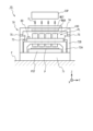
- FIG. 1 is a schematic diagram showing the configuration of an exposure apparatus according to an embodiment.
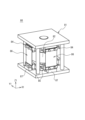
- FIG. 2 is a perspective view of a vibration damping device according to an embodiment.
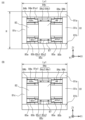
- FIG. 3A is a side view of the vibration damping device as viewed from the -Y1 side
- FIG. 3B is a side view of the vibration damping device as viewed from the +X1 side.
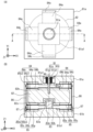
- 4A is a top view of the vibration damping device
- FIG. 4B is a cross-sectional view taken along line AA of FIG. 4A.
- FIG. 5 is a diagram showing a first restraining mechanism according to a modified example.
- the exposure device 10 according to one embodiment will be described with reference to Figures 1 to 4(B).
- FIG. 1 is a diagram that shows roughly the configuration of an exposure apparatus 10 according to the present embodiment.
- the exposure apparatus 10 is a scanning stepper (scanner) that drives the mask MSK and glass substrate (hereafter referred to as "substrate") P in the same direction and at the same speed relative to the projection optical system PL, thereby transferring a pattern formed on the mask MSK onto the substrate P.
- the substrate P is a rectangular glass substrate used, for example, in liquid crystal display devices (flat panel displays), with at least one side or diagonal length of 500 mm or more.
- the direction in which the mask MSK and substrate P are driven during scanning exposure is defined as the X-axis direction
- the direction perpendicular to this in the horizontal plane is defined as the Y-axis direction
- the direction perpendicular to the X-axis and Y-axis is defined as the Z-axis direction
- the directions of rotation (tilt) around the X-axis, Y-axis, and Z-axis are defined as the ⁇ x, ⁇ y, and ⁇ z directions, respectively.
- the exposure apparatus 10 includes an illumination optical system IOP, a mask stage MST that holds a mask MSK, a projection optical system PL, a body 70 that supports these, a substrate stage PST that holds a substrate P, and a control system for these.
- the control system provides overall control of each component of the exposure apparatus 10.
- the body 70 includes a base (vibration isolation table) 71, columns 72A and 72B, an optical base (housing) 73, a support 74, and a slide guide 75.
- the base (vibration isolation table) 71 is placed on a floor F and supports the columns 72A and 72B while isolating vibrations from the floor F.
- the columns 72A and 72B each have a frame shape, and the column 72A is placed inside the column 72B.
- the optical base 73 has, for example, a flat plate shape and is fixed to the ceiling of the column 72A.
- the support 74 is supported by the ceiling of the column 72B via a slide guide 75.
- the slide guide 75 includes an air ball lifter and a positioning mechanism, and positions the support 74 (i.e., the mask stage MST described later) at an appropriate position in the X-axis direction relative to the optical base 73.
- the illumination optical system IOP is disposed above the body 70.
- the illumination optical system IOP irradiates the mask MSK with illumination light IL.
- the mask stage MST is supported by a support 74.
- a mask MSK having a pattern surface (the lower surface in FIG. 1) on which a circuit pattern is formed is fixed to the mask stage MST by, for example, vacuum adsorption (or electrostatic adsorption).
- the mask stage MST is driven by a drive system including, for example, a linear motor at a predetermined stroke in the scanning direction (X-axis direction) and is also slightly driven in the non-scanning directions (Y-axis direction and ⁇ z direction).
- the position information of the mask stage MST in the XY plane is measured by an interferometer system.
- the interferometer system measures the position of the mask stage MST by irradiating a measurement beam onto a movable mirror (or a mirror-finished reflective surface (not shown)) provided at the end of the mask stage MST and receiving the reflected light from the movable mirror.
- the measurement results are supplied to a control device (not shown), which drives the mask stage MST via a drive system in accordance with the measurement results of the interferometer system.
- the projection optical system PL is supported by the optical base 73 below (-Z side) the mask stage MST.
- the projection optical system PL is configured in the same manner as the projection optical system disclosed in, for example, US Pat. No. 5,729,331, and includes a plurality of (for example, seven) projection optical units 100 (multi-lens projection optical units) arranged in a staggered pattern, for example, to form a rectangular image field with the Y-axis direction as the longitudinal direction.
- four projection optical units 100 are arranged at a predetermined interval in the Y-axis direction, and the remaining three projection optical units 100 are arranged at a predetermined interval in the Y-axis direction, spaced apart from the four projection optical units 100 on the +X side.
- each of the multiple projection optical units 100 for example, a system that forms an erect normal image with a two-sided telecentric equal magnification system is used.
- the multiple projection areas of the projection optical units 100 arranged in a staggered pattern are collectively called the exposure area.
- the illumination light IL that has passed through the mask MSK forms a projected image (partial upright image) of the circuit pattern of the mask MSK in the illumination area via the projection optical system PL in an irradiation area (exposure area (conjugate to the illumination area)) on the substrate P arranged on the image plane side of the projection optical system PL.
- a resist sensitizer
- the substrate stage PST By synchronously driving the mask stage MST and the substrate stage PST, i.e., by driving the mask MSK in the scanning direction (X-axis direction) relative to the illumination area (illumination light IL) and driving the substrate P in the same scanning direction relative to the exposure area (illumination light IL), the substrate P is exposed and the pattern of the mask MSK is transferred onto the substrate P.
- the substrate stage PST is placed on a base (vibration isolation table) 71 below (on the -Z side) the projection optical system PL.
- the substrate P is held on the substrate stage PST via a substrate holder (not shown).
- the position information of the substrate stage PST in the XY plane (including rotation information (yawing amount (amount of rotation in the ⁇ z direction ⁇ z), pitching amount (amount of rotation in the ⁇ x direction ⁇ x), and rolling amount (amount of rotation in the ⁇ y direction ⁇ y))) is measured by an interferometer system.
- the interferometer system measures the position of the substrate stage PST by irradiating a measurement beam from the optical base 73 to a movable mirror (or a mirror-finished reflective surface (not shown)) provided at the end of the substrate stage PST and receiving the reflected light from the movable mirror.
- the measurement result is supplied to a control device (not shown), which drives the substrate stage PST in accordance with the measurement result of the interferometer system.
- alignment measurement (e.g., EGA, etc.) is performed prior to exposure, and the results are used to expose the substrate P in the following procedure.
- the mask stage MST and substrate stage PST are synchronously driven in the X-axis direction in accordance with instructions from the control device. This performs scanning exposure on the first shot area on the substrate P.
- the control device moves (steps) the substrate stage PST to a position corresponding to the second shot area. Then, scanning exposure is performed on the second shot area.
- the control device similarly repeats stepping between shot areas of the substrate P and scanning exposure on the shot areas to transfer the pattern of the mask MSK to all shot areas on the substrate P.
- the optical table 73 vibrates during scanning exposure, it affects the exposure accuracy (the accuracy of the pattern formed on the photosensitive material of the substrate P).
- the inventors have discovered through simulation that multiple vibration modes occur in the optical table 73 during scanning exposure. Possible causes of vibration of the optical table 73 include, for example, vibration caused by the operation of the exposure apparatus 10 itself and vibration caused by the surrounding environment of the exposure apparatus 10.
- one or more vibration suppression devices 80 are installed on the optical base 73 to suppress vibration of the optical base 73 that holds the projection optical system PL.
- the structure of the vibration suppression device 80 according to this embodiment will be described in detail with reference to Figures 2 to 4(B).
- the direction in which the weight 82, which will be described later, moves is the Z1 direction
- the directions in which the sides of the flat rectangular lower base part 81b, which will be described later, extend in a plane perpendicular to the Z1 direction are the X1 direction and the Y1 direction.
- the X1 direction, Y1 direction, and Z1 direction are mutually perpendicular.
- FIG. 2 is a perspective view of the vibration damping device 80 according to this embodiment.
- FIG. 3(A) is a side view of the vibration damping device 80 as viewed from the -Y1 side
- FIG. 3(B) is a side view of the vibration damping device 80 as viewed from the +X1 side.
- FIG. 4(A) is a top view of the vibration damping device 80
- FIG. 4(B) is a cross-sectional view taken along line A-A in FIG. 4(A).
- FIG. 4(A) some of the components of the vibration damping device 80 are indicated by dashed lines.
- the vibration control device 80 includes a frame 81, a weight 82 disposed within the frame 81, a plurality of first restraining mechanisms 84 that connect the frame 81 and the weight 82 and allow movement of the weight 82 in the Z1 direction, a plurality of second restraining mechanisms 85 that connect the frame 81 and the weight 82 and allow movement of the weight 82 in the Z1 direction, and a plurality of leaf springs (third restraining mechanisms) 86 that connect the plurality of first restraining mechanisms 84 and the plurality of second restraining mechanisms 85 and restrain movement of the weight 82 in a direction inclined relative to a plane perpendicular to the Z1 direction.
- the frame 81 includes an upper base portion (first member) 81a, a lower base portion (second member) 81b, and a number of support members 81c that connect the upper base portion 81a and the lower base portion 81b.
- the upper base portion 81a and the lower base portion 81b are maintained apart in the Z1 direction by the plurality of support members 81c.
- a weight 82 is disposed between the upper base portion 81a and the lower base portion 81b.
- the weight 82 has, for example, a cylindrical shape.
- a recess 82a is formed on the -Z1 side surface of the weight 82, and the recess 82a houses a part of a stator 83a of a voice coil motor (VCM) 83.
- VCM voice coil motor
- the stator 83a of the VCM 83 is fixed to the lower base portion 81b, and the mover 83b is fixed to the weight 82. As a result, the VCM 83 drives the weight 82 in the Z1 direction between the upper base portion 81a and the lower base portion 81b.
- first restraint mechanisms 84 and four second restraint mechanisms 85 are provided.
- the four first restraint mechanisms 84 connect the upper base portion 81a and the weight 82 and allow movement of the weight 82 in the Z1 direction.
- the multiple first restraint mechanisms 84 also restrain movement of the weight 82 in a plane perpendicular to the Z1 direction and movement of the weight 82 around the Z1 axis of the weight 82 (axis parallel to the Z1 direction).
- the four first restraint mechanisms 84 are arranged at 90 degree intervals in the circumferential direction of a circle centered on the central axis AX of the weight 82.
- the vibration control device 80 is installed with the X1 or Y1 direction parallel to the direction of gravity (with the Z1 direction parallel to the horizontal direction), for example, it is possible to permit movement of the weight 82 in the Z1 direction while restricting movement of the weight 82 in a plane perpendicular to the Z1 direction and movement of the weight 82 around the Z1 axis.
- Each first restraining mechanism 84 includes a first leaf spring (first leaf spring portion) 84a, a second leaf spring (second leaf spring portion) 84b, and a first connecting portion 84c.
- One end of the first leaf spring 84a is connected to a fixed portion 81a1 provided on the upper base portion 81a, and the other end of the first leaf spring 84a is connected to a first fixed portion 84c1 of the first connecting portion 84c.
- One end of the second leaf spring 84b is connected to an upper fixed portion 82b fixed to the end face on the +Z1 side of the weight 82, and the other end of the second leaf spring 84b is connected to the first fixed portion 84c1 of the first connecting portion 84c.
- the upper base part 81a and the weight 82 are connected using two leaf springs that extend in parallel with their other ends connected to each other.
- the distance (stroke) that the weight 82 can move in the Z1 direction can be made longer than when the upper base part 81a and the weight 82 are connected using a single leaf spring of the same length.
- the four second restraining mechanisms 85 connect the lower base portion 81b and the weight 82, and allow movement of the weight 82 in the Z1 direction.
- the four second restraining mechanisms 85 also restrain movement of the weight 82 in a plane perpendicular to the Z1 direction and movement of the weight 82 around the Z1 axis.
- the four second restraining mechanisms 85 are positioned to face the four first restraining mechanisms 84 in the Z1 direction.
- Each second restraining mechanism 85 includes a third leaf spring (third leaf spring portion) 85a, a fourth leaf spring (fourth leaf spring portion) 85b, and a second connecting portion 85c.
- One end of the third leaf spring 85a is connected to a fixed portion 81b1 provided on the lower base portion 81b, and the other end of the third leaf spring 85a is connected to a first fixed portion 85c1 of the second connecting portion 85c.
- One end of the fourth leaf spring 85b is connected to a lower fixed portion 82c fixed to the end face on the -Z1 side of the weight 82, and the other end of the fourth leaf spring 85b is connected to the first fixed portion 85c1 of the second connecting portion 85c.
- the distance (stroke) that the weight 82 can move in the Z1 direction can be made longer than when connecting the lower base part 81b and the weight 82 using a single leaf spring of the same length.
- each of the first leaf spring 84a, the second leaf spring 84b, the third leaf spring 85a, and the fourth leaf spring 85b is determined based on the weight of the weight 82 and the frequency at which vibration is to be damped.
- the leaf spring (third restraining mechanism) 86 connects the first restraining mechanism 84 and the second restraining mechanism 85, and restrains the movement of the weight 82 in a direction inclined relative to a plane perpendicular to the Z1 direction.
- one end of the leaf spring 86 is connected to the second fixed portion 84c2 of the first connecting portion 84c of the first restraining mechanism 84, and the other end of the leaf spring 86 is connected to the second fixed portion 85c2 of the second connecting portion 85c of the second restraining mechanism 85.
- a vibration absorbing member 87 is installed between the lower base portion 81b and the second fixing portion 85c2 of the second connecting portion 85c.
- the end of the vibration absorbing member 87 on the -Z1 side is fixed to the lower base portion 81b.
- the end of the vibration absorbing member 87 on the +Z1 side is not fixed to any member. Since the second fixing portion 85c2 of the second connecting portion 85c is part of the second restraining mechanism 85, it can be said that the vibration absorbing member 87 is installed between the lower base portion 81b and the second restraining mechanism 85.
- the vibration absorbing member 87 is installed between the lower base portion 81b and the leaf spring 86.
- the vibration absorbing member 87 may be installed between the lower base portion 81b and the first fixing portion 85c1 of the second connecting portion 85c.
- the vibration absorbing member 87 absorbs vibrations (resonance) of the leaf spring 86 caused by unwanted vibration modes occurring in the vibration control device 80.
- Materials for the vibration absorbing member 87 include those that convert the kinetic energy of vibrations into energy such as heat or sound to dampen vibrations.
- viscoelastic materials polymers, viscous fluids, and microparticle-filled structures
- a polymer is Sorbothane (registered trademark).
- An example of a material that uses a viscous fluid is a damper that uses oil or water.
- the vibration damping device 80 further includes a weight compensation mechanism 91 that compensates for the weight of the weight 82.
- the weight compensation mechanism 91 includes a support portion 91a and a compression coil spring 91b.
- the support portion 91a has a generally T-shaped cross section and includes a spring engagement portion 91a1 that intersects with the Z1 direction and an extension portion 91a2 that extends from the spring engagement portion 91a1 in the -Z1 direction.
- the extension portion 91a2 is connected to the weight 82.
- the spring force of the compression coil spring 91b is set so that the first leaf spring 84a, the second leaf spring 84b, the third leaf spring 85a, and the fourth leaf spring 85b are parallel to a plane perpendicular to the Z1 direction when the weight 82 is stationary. In other words, when the weight 82 is stationary, the position of the weight 82 is maintained at the center of the stroke.
- the spring constant of the compression coil spring 91b it is desirable for the spring constant of the compression coil spring 91b to be as small as possible in order to reduce the loss of thrust of the VCM 83.
- the lengths Lx1 and Ly1 of the vibration damping device 80 in the X1 and Y1 directions are, for example, 120 mm to 130 mm, respectively, and the height H of the vibration damping device 80 is, for example, 123 mm to 129 mm. Note that the size of the vibration damping device 80 is not limited to this.
- the vibration suppression device 80 is placed on the optical base plate 73 so that the movement direction (Z1 direction) of the weight 82 coincides with the direction of gravity (Z direction in FIG. 1).
- the vibration suppression device 80 is placed on the optical base plate 73 so that the lower base portion 81b is in contact with the upper surface of the optical base plate 73.
- the vibration damping device 80 it is preferable to provide the vibration damping device 80 at a position other than the node of at least one of the vibration modes to be damped among the multiple vibration modes that occur in the optical table 73. This is because if the vibration damping device 80 is provided at the node of the vibration mode, driving the vibration damping device 80 will not contribute to damping of the vibration mode. It is more preferable to provide the vibration damping device 80 in an area where it can contribute to damping of the vibration mode, and even more preferable to provide it near the abdomen of the vibration mode where the vibration displacement is particularly large.
- VCM 83 By using the VCM 83 to move the weight 82 in the Z1 direction at a frequency corresponding to the frequency of the vibration mode to be damped, it is possible to suppress vibration at the frequency of the vibration mode to be damped among the vibration modes that occur in the optical table 73.
- the vibration damping device 80 when two vibration modes, for example, of the multiple vibration modes occurring in the optical table 73, are to be damped, it is preferable to install the vibration damping device 80 in a range where the non-node portion of one vibration mode overlaps with the non-node portion of the other vibration mode. It is more preferable to install the vibration damping device 80 in an area that can contribute to the damping of the two vibration modes, and especially when the abdomens where the vibration displacements of the two vibration modes are large are close, it is even more preferable to install the vibration damping device 80 in the vicinity (for example, the intermediate position between the positions where the abdomens of the two vibration modes occur).
- the weight 82 By moving the weight 82 in the Z1 direction by the VCM 83 at a frequency corresponding to each of the two vibration modes, it is possible to suppress the optical table 73 from vibrating at the frequency of the two vibration modes. This can improve the exposure accuracy of the exposure device 10.
- the weight of the weight 82 can be significantly reduced compared to the case where a passive mass damper is used.
- the vibration control device 80 may be installed in one location or in multiple locations.
- the vibration damping device 80 comprises a frame 81 having an upper base portion 81a and a lower base portion 81b which are maintained spaced apart in the Z1 direction, a weight 82 arranged between the upper base portion 81a and the lower base portion 81b, and a VCM 83 which drives the weight 82 in the Z1 direction between the upper base portion 81a and the lower base portion 81b.
- the vibration damping device 80 includes a plurality of first restraining mechanisms 84 each having a first leaf spring 84a and a second leaf spring 84b that connect the upper base portion 81a and the weight 82 and allow movement of the weight 82 in the Z1 direction, a plurality of second restraining mechanisms 85 each having a third leaf spring 85a and a fourth leaf spring 85b that connect the lower base portion 81b and the weight 82 and allow movement of the weight 82 in the Z1 direction, and a plurality of leaf springs 86 that connect the plurality of first restraining mechanisms 84 and the plurality of second restraining mechanisms 85 and restrain movement of the weight 82 in a direction inclined with respect to a plane perpendicular to the Z1 direction.
- the multiple first restraint mechanisms 84 restrain the movement of the weight 82 in a plane perpendicular to the Z1 direction and the movement of the weight 82 around the Z1 axis
- the multiple second restraint mechanisms 85 restrain the movement of the weight 82 in a plane perpendicular to the Z1 direction and the movement of the weight 82 around the Z1 axis.
- Mechanisms for allowing movement of weight 82 in the Z1 direction while restricting movement of weight 82 in a plane perpendicular to the Z1 direction and around the Z1 axis include, for example, sliding guides such as LM guides and air guides.
- sliding guides repeated bending stress caused by vibration of the sliding guide causes wear on the guide surface, and it is difficult to ensure stable vibration control performance for a long period of time due to the associated changes in characteristics (for example, sliding friction resistance).
- maintenance such as lubrication is required.
- non-contact guides such as air guides do not wear out and therefore do not change in characteristics, but they require power (compressed air) when in use and it is difficult to ensure load capacity (allowable load).
- a leaf spring is used as a mechanism for allowing movement of the weight 82 in the Z1 direction while restricting movement of the weight 82 in a plane perpendicular to the Z1 direction and around the Z1 axis, so that stable vibration control performance can be ensured for a long period of time without wear. Furthermore, maintenance is also easy. Furthermore, leaf springs are less expensive than LM guides and air guides, so the component costs of the vibration control device 80 can also be reduced.
- each of the first restraining mechanisms 84 includes a first leaf spring 84a connected to the upper base portion 81a, a second leaf spring 84b connected to the weight 82, and a first connecting portion 84c connecting the first leaf spring 84a and the second leaf spring 84b.
- Each of the second restraining mechanisms 85 includes a third leaf spring 85a connected to the lower base portion 81b, a fourth leaf spring 85b connected to the weight 82, and a second connecting portion 85c connecting the third leaf spring 85a and the fourth leaf spring 85b. As shown in FIG.
- the distance (stroke) over which the weight 82 can move can be made longer than when a single leaf spring of the same length is used.
- the two leaf springs may be connected in a V-shape instead of a U-shape.
- the vibration control device 80 includes a plurality of vibration absorbing members 87 that respectively absorb the vibrations of the plurality of leaf springs 86. This makes it possible to attenuate and suppress resonance of unnecessary vibration modes that occur within the vibration control device 80.
- the vibration control device 80 includes a weight compensation mechanism 91 that compensates for the weight of the weight 82. This allows the position of the weight 82 to be held at the center of the stroke when the weight 82 is stationary, ensuring a sufficient stroke when the weight 82 is driven. In addition, the load on the VCM 83 can be reduced when the weight 82 is driven.
- the first restraining mechanism 84 includes the first leaf spring 84a, the second leaf spring 84b, and the first connecting portion 84c, but the first restraining mechanism 84 may be realized by a single leaf spring.
- FIG. 5 is a diagram showing a first restraining mechanism 84A according to a modified example.
- the first restraining mechanism 84A includes a first leaf spring portion 84Aa, a second leaf spring portion 84Ab, and a connecting portion 84Ac that connects the first leaf spring portion 84Aa and the second leaf spring portion 84Ab, and the first leaf spring portion 84Aa, the second leaf spring portion 84Ab, and the connecting portion 84Ac are formed by a single leaf spring.
- the first restraining mechanism 84A is realized by bending a single leaf spring into a U-shape.
- the upper base portion 81a and the weight 82 may be connected.
- the leaf spring 86 may be soldered to the connecting portion 84Ac of the first restraining mechanism 84A, or as shown in FIG. 5, a fixing member 88 may be provided to connect the first restraining mechanism 84A and the leaf spring 86.
- the first restraining mechanism 84A may be realized by bending a single leaf spring into a V-shape instead of a U-shape.
- the leaf spring 86 is used as the third restraint mechanism that connects the first restraint mechanism 84 and the second restraint mechanism 85, but this is not limited to this.
- the mechanism that connects the first restraint mechanism 84 and the second restraint mechanism 85 may be a member other than a leaf spring as long as it does not expand or contract in the Z1 direction.
- the vibration damping device 80 is provided with four first constraint mechanisms 84 and four second constraint mechanisms 85, but this is not limited to this.
- the vibration damping device 80 is installed with the Z1 direction parallel to the direction of gravity, at least three first constraint mechanisms 84 are required, and at least three second constraint mechanisms 85 are required.
- the number of first constraint mechanisms 84 and the number of second constraint mechanisms 85 may each be five or more.
- one end of the vibration absorbing member 87 is fixed to the lower base portion 81b, but this is not limited to the above.
- One end of the vibration absorbing member 87 may be fixed to a separate member fixed to the lower base portion 81b.
- one end of the vibration absorbing member 87 may be fixed to a support member 81c that connects the upper base portion 81a and the lower base portion 81b.
- one end of the vibration absorbing member 87 may not be a component of the vibration control device 80, but may be fixed, for example, to the optical base plate 73 or another member fixed to the optical base plate 73.
- the vibration absorbing member 87 is provided between the lower base portion 81b and the leaf spring 86, but the vibration absorbing member 87 may be provided between the upper base portion 81a and the leaf spring 86, or between the upper base portion 81a and the first restraining mechanism 84. The other end of the vibration absorbing member 87 may be connected to an end of the leaf spring 86.
- the weight 82 is driven in the Z1 direction by the VCM 83, but this is not limited to this.
- a piezoelectric element, a linear motor, or the like may be used instead of the VCM 83.
- the vibration damping device 80 was installed on the optical base 73, but this is not limited thereto, and the vibration damping device 80 can be installed in any part in the exposure apparatus 10 in which vibrations need to be suppressed.
- the vibration damping device 80 may also be installed in an apparatus other than the exposure apparatus 10.
- the vibration damping device 80 is installed so that its Z1 direction is parallel to the direction of gravity. However, depending on the direction of vibration generated in the component, the vibration damping device 80 may be installed so that its Z1 direction is parallel to the horizontal direction (so that its X1 or Y1 direction is parallel to the direction of gravity). The vibration damping device 80 may also be installed so that its Z1 direction is inclined relative to the direction of gravity.
- a leaf spring is used as a mechanism for allowing movement of the weight 82 in the Z1 direction while restricting movement of the weight 82 in a plane perpendicular to the Z1 direction and movement of the weight 82 around the Z1 axis, making it possible to increase the weight of the weight 82.
- the vibration control device 80 If the vibration control device 80 is installed so that the Z1 direction is parallel to the horizontal direction (so that the X1 or Y1 direction is parallel to the direction of gravity), the weight compensation mechanism 91 may be omitted.
- the exposure apparatus 10 is described as being a scanning stepper, but this is not limiting, and the exposure apparatus 10 may be a stationary exposure apparatus such as a stepper, or a step-and-stitch type reduced projection exposure apparatus that combines shot areas.
- a spatial light modulator having multiple spatial light modulation elements may be used instead of the mask MSK.
- the pattern image generated by the spatial light modulator is scanned and exposed onto the substrate P.
- Exposure device 80 Vibration suppression device 81 Frame body 81a Upper base portion 81b Lower base portion 81c Support member 82 Weight 83 VCM 84, 84A First restraining mechanism 84a First leaf spring 84Aa First leaf spring portion 84b Second leaf spring 84Ab Second leaf spring portion 84c First connecting portion 84Ac Connecting portion 85 Second restraining mechanism 85a Third leaf spring 85b Fourth leaf spring 86
- Leaf spring 87 Vibration absorbing member 91
- Weight compensation mechanism 73 Optical table IOP Illumination system MSK Mask P Substrate PL Projection optical system
Landscapes
- Engineering & Computer Science (AREA)
- Physics & Mathematics (AREA)
- Health & Medical Sciences (AREA)
- General Engineering & Computer Science (AREA)
- General Physics & Mathematics (AREA)
- Environmental & Geological Engineering (AREA)
- Epidemiology (AREA)
- Public Health (AREA)
- Mechanical Engineering (AREA)
- Atmospheric Sciences (AREA)
- Life Sciences & Earth Sciences (AREA)
- Aviation & Aerospace Engineering (AREA)
- Toxicology (AREA)
- Acoustics & Sound (AREA)
- Electromagnetism (AREA)
- Exposure Of Semiconductors, Excluding Electron Or Ion Beam Exposure (AREA)
- Exposure And Positioning Against Photoresist Photosensitive Materials (AREA)
- Vibration Prevention Devices (AREA)
Abstract
Description
図1は、本実施形態に係る露光装置10の構成を概略的に示す図である。
80 制振装置
81 枠体
81a 上ベース部
81b 下ベース部
81c 支持部材
82 錘
83 VCM
84,84A 第1拘束機構
84a 第1板バネ
84Aa 第1板バネ部
84b 第2板バネ
84Ab 第2板バネ部
84c 第1連結部
84Ac 連結部
85 第2拘束機構
85a 第3板バネ
85b 第4板バネ
86 板バネ
87 振動吸収部材
91 自重補償機構
73 光学定盤
IOP 照明系
MSK マスク
P 基板
PL 投影光学系
Claims (16)
- 第1方向に離間した状態が維持されている第1部材と第2部材とを有する枠体と、
前記第1部材と前記第2部材との間に配置された錘と、
前記第1部材と前記第2部材との間において、前記錘を前記第1方向に駆動するアクチュエータと、
前記第1部材と前記錘とを連結するとともに、前記第1方向への前記錘の移動を許容する、1または複数の板バネを各々有する複数の第1拘束機構と、
前記第2部材と前記錘とを連結するとともに、前記第1方向への前記錘の移動を許容する、1または複数の板バネを各々有する複数の第2拘束機構と、
前記複数の第1拘束機構と前記複数の第2拘束機構とを連結し、前記第1方向と垂直な面に対し傾斜する方向の前記錘の移動を拘束する複数の第3拘束機構と、
を備える制振装置。 - 前記複数の第1拘束機構は、前記第1方向と垂直な面内における前記錘の移動と、前記第1方向と平行な第1軸周りの前記錘の移動と、を拘束し、
前記複数の第2拘束機構は、前記第1方向と垂直な面内における前記錘の移動と、前記第1軸周りの前記錘の移動と、を拘束する、
請求項1に記載の制振装置。 - 前記複数の第1拘束機構は各々、
前記第1部材に接続された第1板バネ部と、
前記錘に接続された第2板バネ部と、
前記第1板バネ部と前記第2板バネ部とを連結する第1連結部と、
を含み、
前記複数の第2拘束機構は各々、
前記第2部材に接続された第3板バネ部と、
前記錘に接続された第4板バネ部と、
前記第3板バネ部と前記第4板バネ部とを連結する第2連結部と、
を含む、
請求項1または請求項2に記載の制振装置。 - 前記第1板バネ部と、前記第2板バネ部と、前記第1連結部と、は、1枚の板バネで形成されており、
前記第3板バネ部と、前記第4板バネ部と、前記第2連結部と、は、1枚の板バネで形成されている、
請求項3に記載の制振装置。 - 前記複数の第1拘束機構は、前記第1方向と平行な第1軸を中心とする円の周方向において少なくとも3箇所に配置され、
前記複数の第2拘束機構は、前記複数の第1拘束機構と前記第1方向において対向するように配置されている、
請求項1から請求項4のいずれか一項に記載の制振装置。 - 前記複数の第3拘束機構の各々は板バネである、
請求項1から請求項5のいずれか一項に記載の制振装置。 - 前記複数の第3拘束機構の振動をそれぞれ吸収する複数の振動吸収部材を備える、
請求項1から請求項6のいずれか一項に記載の制振装置。 - 前記複数の振動吸収部材は、前記第1部材と前記複数の第1拘束機構との間、前記第2部材と前記複数の第2拘束機構との間、前記第1部材と前記複数の第3拘束機構との間、又は前記第2部材と前記複数の第3拘束機構との間にそれぞれ設けられている、
請求項7に記載の制振装置。 - 前記錘の自重を補償する自重補償機構を備える、
請求項1から請求項8のいずれか一項記載の制振装置。 - 前記アクチュエータは、ボイスコイルモータである、
請求項1から請求項9のいずれか一項に記載の制振装置。 - 前記複数の第1拘束機構の各々が備える前記1または複数の板バネの厚みと、前記複数の第2拘束機構の各々が備える前記1または複数の板バネの厚みと、は、前記錘の重量と、制振したい周波数と、に基づいて決定される、
請求項1から請求項10のいずれか一項に記載の制振装置。 - 前記第1部材と前記第2部材とを連結する支持部材を備える、
請求項1から請求項11のいずれか一項に記載の制振装置。 - 第1物体のパターン像を第2物体上に露光する露光装置であって、
露光光で前記第1物体を照明する照明光学系と、
前記第1物体からの前記露光光を第2物体上に投影する投影光学系と、
前記投影光学系を支持する筐体と、
請求項1から請求項10のいずれか一項に記載の制振装置と、
を備え、
前記制振装置は、前記筐体に発生する複数の振動モードのうちの少なくとも1つの振動モードの腹部に相当する位置付近に配置される、
露光装置。 - 前記第2物体は、少なくとも一辺の長さ又は対角長が500mm以上である感光性基板である、
請求項13に記載の露光装置。 - 前記アクチュエータは、前記少なくとも1つの振動モードの周波数に応じた周波数で前記錘を前記第1方向に移動させる、
請求項13または請求項14に記載の露光装置。 - 請求項13から請求項15のいずれか一項に記載の露光装置を用いた露光方法であって、
前記照明光学系を用いて前記露光光で前記第1物体を照明することと、
前記投影光学系を用いて前記第1物体のパターン像を前記第2物体へ投影することと、
を含む露光方法。
Priority Applications (6)
| Application Number | Priority Date | Filing Date | Title |
|---|---|---|---|
| PCT/JP2023/013687 WO2024202056A1 (ja) | 2023-03-31 | 2023-03-31 | 制振装置、露光装置、及び露光方法 |
| KR1020257028424A KR20250138259A (ko) | 2023-03-31 | 2023-03-31 | 제진 장치, 노광 장치, 및 노광 방법 |
| CN202380096309.2A CN120898087A (zh) | 2023-03-31 | 2023-03-31 | 减振装置、曝光装置及曝光方法 |
| JP2025509635A JPWO2024202056A1 (ja) | 2023-03-31 | 2023-03-31 | |
| TW113111246A TW202441593A (zh) | 2023-03-31 | 2024-03-26 | 減振裝置、曝光裝置、及曝光方法 |
| US19/262,731 US20250334891A1 (en) | 2023-03-31 | 2025-07-08 | Vibration damping device, exposure device, and exposure method |
Applications Claiming Priority (1)
| Application Number | Priority Date | Filing Date | Title |
|---|---|---|---|
| PCT/JP2023/013687 WO2024202056A1 (ja) | 2023-03-31 | 2023-03-31 | 制振装置、露光装置、及び露光方法 |
Related Child Applications (1)
| Application Number | Title | Priority Date | Filing Date |
|---|---|---|---|
| US19/262,731 Continuation US20250334891A1 (en) | 2023-03-31 | 2025-07-08 | Vibration damping device, exposure device, and exposure method |
Publications (1)
| Publication Number | Publication Date |
|---|---|
| WO2024202056A1 true WO2024202056A1 (ja) | 2024-10-03 |
Family
ID=92904549
Family Applications (1)
| Application Number | Title | Priority Date | Filing Date |
|---|---|---|---|
| PCT/JP2023/013687 Ceased WO2024202056A1 (ja) | 2023-03-31 | 2023-03-31 | 制振装置、露光装置、及び露光方法 |
Country Status (6)
| Country | Link |
|---|---|
| US (1) | US20250334891A1 (ja) |
| JP (1) | JPWO2024202056A1 (ja) |
| KR (1) | KR20250138259A (ja) |
| CN (1) | CN120898087A (ja) |
| TW (1) | TW202441593A (ja) |
| WO (1) | WO2024202056A1 (ja) |
Citations (5)
| Publication number | Priority date | Publication date | Assignee | Title |
|---|---|---|---|---|
| JPS5167902A (en) * | 1974-12-10 | 1976-06-12 | Matsushita Electric Industrial Co Ltd | Kaitenkudosochi |
| JPS6392850A (ja) * | 1986-10-03 | 1988-04-23 | Ishikawajima Harima Heavy Ind Co Ltd | 防振装置 |
| JP2002198292A (ja) * | 2000-12-26 | 2002-07-12 | Nikon Corp | 露光装置 |
| JP2005030486A (ja) * | 2003-07-11 | 2005-02-03 | Nikon Corp | 制振装置及びステージ装置並びに露光装置 |
| US7550880B1 (en) * | 2006-04-12 | 2009-06-23 | Motran Industries Inc | Folded spring flexure suspension for linearly actuated devices |
Family Cites Families (1)
| Publication number | Priority date | Publication date | Assignee | Title |
|---|---|---|---|---|
| JP2015081993A (ja) | 2013-10-22 | 2015-04-27 | キヤノン株式会社 | ステージ装置、露光装置、およびデバイス製造方法 |
-
2023
- 2023-03-31 JP JP2025509635A patent/JPWO2024202056A1/ja active Pending
- 2023-03-31 WO PCT/JP2023/013687 patent/WO2024202056A1/ja not_active Ceased
- 2023-03-31 KR KR1020257028424A patent/KR20250138259A/ko active Pending
- 2023-03-31 CN CN202380096309.2A patent/CN120898087A/zh active Pending
-
2024
- 2024-03-26 TW TW113111246A patent/TW202441593A/zh unknown
-
2025
- 2025-07-08 US US19/262,731 patent/US20250334891A1/en active Pending
Patent Citations (5)
| Publication number | Priority date | Publication date | Assignee | Title |
|---|---|---|---|---|
| JPS5167902A (en) * | 1974-12-10 | 1976-06-12 | Matsushita Electric Industrial Co Ltd | Kaitenkudosochi |
| JPS6392850A (ja) * | 1986-10-03 | 1988-04-23 | Ishikawajima Harima Heavy Ind Co Ltd | 防振装置 |
| JP2002198292A (ja) * | 2000-12-26 | 2002-07-12 | Nikon Corp | 露光装置 |
| JP2005030486A (ja) * | 2003-07-11 | 2005-02-03 | Nikon Corp | 制振装置及びステージ装置並びに露光装置 |
| US7550880B1 (en) * | 2006-04-12 | 2009-06-23 | Motran Industries Inc | Folded spring flexure suspension for linearly actuated devices |
Also Published As
| Publication number | Publication date |
|---|---|
| CN120898087A (zh) | 2025-11-04 |
| KR20250138259A (ko) | 2025-09-19 |
| JPWO2024202056A1 (ja) | 2024-10-03 |
| US20250334891A1 (en) | 2025-10-30 |
| TW202441593A (zh) | 2024-10-16 |
Similar Documents
| Publication | Publication Date | Title |
|---|---|---|
| US10514616B2 (en) | Movable body apparatus, exposure apparatus and device manufacturing method | |
| CN101446771B (zh) | 具有主动阻尼组件的光刻设备 | |
| US6894449B2 (en) | Vibration control device, stage device and exposure apparatus | |
| US9134632B2 (en) | Lithographic apparatus and device manufacturing method | |
| JP2003264147A (ja) | ホトリソグラフィ装置及び露光方法 | |
| US20090195767A1 (en) | Exposure apparatus and device manufacturing method | |
| CN101855705A (zh) | 驱动控制方法、驱动控制装置、载台控制方法、载台控制装置、曝光方法、曝光装置以及计测装置 | |
| US20260140455A1 (en) | Stage apparatus, exposure apparatus, method of manufacturing flat panel display, and device manufacturing method | |
| TW200305194A (en) | Method, system, and apparatus for management of reaction loads in a lithography system | |
| US8184266B2 (en) | Lithographic apparatus and device manufacturing method | |
| US20080013058A1 (en) | Pneumatic Spring Apparatus, Vibration-Proof Apparatus, Stage Apparatus and Exposure Apparatus | |
| US20090051889A1 (en) | Optical element driving apparatus, projection optical system, exposure apparatus and device manufacturing method | |
| US20070236854A1 (en) | Anti-Gravity Device for Supporting Weight and Reducing Transmissibility | |
| US20250334891A1 (en) | Vibration damping device, exposure device, and exposure method | |
| JP2011244608A (ja) | リニアモータ、移動体装置、露光装置、デバイス製造方法、及びフラットパネルディスプレイの製造方法 | |
| JPH11317350A (ja) | ステージ装置、露光装置およびデバイス製造方法 | |
| EP4720775A1 (en) | Damper, method for damping, and apparatus including a damper | |
| US20030223051A1 (en) | Floor support with passive shear wave cancellation | |
| HK1228517A (en) | Exposure apparatus, movable body apparatus, flat-panel display manufacturing method, and device manufacturing method |
Legal Events
| Date | Code | Title | Description |
|---|---|---|---|
| 121 | Ep: the epo has been informed by wipo that ep was designated in this application |
Ref document number: 23930690 Country of ref document: EP Kind code of ref document: A1 |
|
| WWE | Wipo information: entry into national phase |
Ref document number: 2025509635 Country of ref document: JP |
|
| ENP | Entry into the national phase |
Ref document number: 1020257028424 Country of ref document: KR Free format text: ST27 STATUS EVENT CODE: A-0-1-A10-A15-NAP-PA0105 (AS PROVIDED BY THE NATIONAL OFFICE) |
|
| WWE | Wipo information: entry into national phase |
Ref document number: 202380096309.2 Country of ref document: CN |
|
| NENP | Non-entry into the national phase |
Ref country code: DE |
|
| WWP | Wipo information: published in national office |
Ref document number: 202380096309.2 Country of ref document: CN |
|
| 122 | Ep: pct application non-entry in european phase |
Ref document number: 23930690 Country of ref document: EP Kind code of ref document: A1 |