WO2024202002A1 - 管路通過試験システム及び方法 - Google Patents
管路通過試験システム及び方法 Download PDFInfo
- Publication number
- WO2024202002A1 WO2024202002A1 PCT/JP2023/013538 JP2023013538W WO2024202002A1 WO 2024202002 A1 WO2024202002 A1 WO 2024202002A1 JP 2023013538 W JP2023013538 W JP 2023013538W WO 2024202002 A1 WO2024202002 A1 WO 2024202002A1
- Authority
- WO
- WIPO (PCT)
- Prior art keywords
- pipeline
- wireless signal
- receiver
- power
- processing unit
- Prior art date
- Legal status (The legal status is an assumption and is not a legal conclusion. Google has not performed a legal analysis and makes no representation as to the accuracy of the status listed.)
- Ceased
Links
Images


Classifications
-
- G—PHYSICS
- G01—MEASURING; TESTING
- G01M—TESTING STATIC OR DYNAMIC BALANCE OF MACHINES OR STRUCTURES; TESTING OF STRUCTURES OR APPARATUS, NOT OTHERWISE PROVIDED FOR
- G01M99/00—Subject matter not provided for in other groups of this subclass
Definitions
- This disclosure relates to a pipeline passage test system and method for determining the integrity of installed pipelines.
- conduit passage test is conducted to check that the conduit is sound and that the optical cable can be passed through.
- a cylindrical wooden or plastic mandrel is inserted into the conduit and pulled to see if the mandrel can pass through.
- a similar conduit passage test is also used to check the construction of the conduit.
- pipeline passage tests using mandrels not only take time because the mandrel must be pulled, but also require large, specialized tools. In other words, there is an issue with pipeline passage tests using mandrels, in that it is difficult to perform the test easily and quickly.
- the present invention aims to solve the above problems by providing a pipeline passage test system and method that can test the condition of installed pipelines easily and quickly.
- the pipeline passage test system of the present invention performs pipeline passage tests using wireless sensing means that uses a small, general-purpose transmitting and receiving device that transmits and receives radio waves or sound waves.
- the pipeline passage test system comprises: A transmitter installed at one end of a pipeline for injecting a wireless signal into the pipeline; a receiver that is installed at the other end of the pipeline and receives the wireless signal that has passed through the pipeline; an analysis processing unit that judges the quality of the pipeline based on the reception power of the wireless signal received by the receiver; Equipped with.
- the method for pipeline passage test includes the steps of: Installing a transmitter at one end of a pipeline and injecting a wireless signal into the pipeline; a receiver is installed at the other end of the pipeline and receives the radio signal that has passed through the pipeline; and determining whether the pipeline is good or bad based on a reception power of the radio signal received by the receiver. It is characterized by:
- the pipeline passage test system and method according to the present invention transmit and receive radio waves or sound waves, and determine the integrity of the pipeline from the ratio of received power to transmitted power. Because no mandrel is used, and a general-purpose transmitting and receiving device is used, testing can be performed easily and quickly.
- the present invention can provide a pipeline passage test system and method that can test the condition of an installed pipeline easily and quickly.
- the analysis processing unit of the pipeline passage test system comprises: The received power P of the wireless signal when the length of the pipe is zero, an ideal attenuation constant ⁇ (l) for the power of the radio signal, which depends on the length l of the pipe; and an attenuation constant ⁇ ′(s) for the power of the radio signal, which depends on the effective cross-sectional area s of the pipe; is given,
- the attenuation amount Psig of the radio signal in the pipeline is expressed as Pin ⁇ (l) ⁇ '(s), and the effective cross-sectional area s of the pipeline is estimated from the attenuation constant ⁇ '(s).
- the method for pipeline passage test includes the steps of: When P is a received power of the radio signal when the length of the pipe is zero, ⁇ (l) is an ideal attenuation constant for the power of the radio signal that depends on the length l of the pipe, and ⁇ ′(s) is an attenuation constant for the power of the radio signal that depends on the effective cross-sectional area s of the pipe,
- the attenuation amount Psig of the radio signal in the pipeline is expressed as Pin ⁇ (l) ⁇ '(s), and the effective cross-sectional area s of the pipeline is estimated from the attenuation constant ⁇ '(s).
- the analysis processing unit of the pipeline passage test system is characterized in that it determines that the pipeline is defective when the estimated effective cross-sectional area s of the pipeline is smaller than a threshold value.
- the analysis processing unit of the pipeline passage test system is characterized in that the attenuation constant ⁇ (l) is given for each cross-sectional shape, cross-sectional area, material, and surface roughness of the inner wall of a healthy pipeline, as well as for each frequency of the wireless signal.
- the analysis processing unit of the pipeline passage test system is characterized in that the attenuation constant ⁇ '(s) is given for each cross-sectional shape, material, and surface roughness of the inner wall of a healthy pipeline, as well as for each frequency of the wireless signal.
- the analysis processing unit of the pipeline passage test system according to the present invention is characterized in that a noise level is given, and when the received power is smaller than the noise level, the analysis processing unit judges the pipeline to be defective.
- the analysis processing unit can also be realized by a computer and a program, and the program can be recorded on a recording medium or provided via a network.
- the present invention can provide a pipeline passage test system and method that can test the condition of installed pipelines easily and quickly.
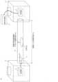
- FIG. 1 is a diagram illustrating a pipeline passage test system according to the present invention.
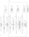
- FIG. 2 is a diagram illustrating a pipeline passage test method according to the present invention.
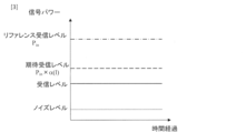
- FIG. 4 is a diagram (power diagram) explaining the levels of each signal received by a receiver of the pipeline passage testing system according to the present invention.
- FIG. 1 is a diagram illustrating attenuation constants ⁇ (l) and ⁇ '(s) in a pipe.
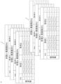
- FIG. 13 is a diagram for explaining the attenuation constant ⁇ (l) stored in the analysis processing unit of the pipeline passage test system according to the present invention.
- FIG. 13 is a diagram for explaining the attenuation constant ⁇ '(s) stored in the analysis processing unit of the pipeline passage test system according to the present invention.
- FIG. 1 is a diagram illustrating a pipeline passage test system according to the present embodiment.
- a transmitter 11 is installed at one end of a pipeline 50 and transmits a wireless signal 21 to the pipeline 50; a receiver 12 that is installed at the other end of the pipeline 50 and receives the radio signal 21 that has passed through the pipeline 50; an analysis processing unit that judges the quality of the pipeline from the reception power of the wireless signal received by the receiver; Equipped with.
- the transmitter 11 is installed in the transmitting manhole or handhole 30 and outputs radio waves or sound waves as a radio signal 21.
- the receiver 12 is installed in the receiving manhole or handhole 30 connected via a pipeline 50 and receives the radio signal 21 of radio waves or sound waves that has propagated through the pipeline 50.
- the analysis processing unit 13 analyzes the power or sound pressure level of the radio signal 21 received by the receiver 12 and estimates the effective cross-sectional area of the pipeline 50.
- a pipeline that is free of cracks, corrosion, and the inflow of sediment or the like is referred to as a "healthy pipeline,” and a pipeline that has been partially or entirely infiltrated with sediment or the like, narrowing gaps within the pipeline or causing blockage is referred to as an "unhealthy pipeline.”
- the "effective cross-sectional area of pipeline 50" is the cross-sectional area of pipeline 50 determined from the power or sound pressure level of radio signal 21 received by receiver 12; when the inflow of sediment or the like narrows the gaps within pipeline 50, the power or sound pressure level of radio signal 21 received by receiver 12 decreases, and the "effective cross-sectional area of pipeline 50" becomes smaller.
- the wireless signal 21 is a radio wave
- a commonly used Wi-Fi or radar transmitter can be used for the transmitter 11.
- radio waves of multiple frequencies may be used.
- the receiver 12 may be a Wi-Fi or radar receiver that is widely used.
- the transmitter 11 and the receiver 12 are used in combination according to the type of radio wave.
- the transmitter 11 can be a sound source or a speaker.
- the receiver 12 can be a microphone or a sound level meter.
- the transmitter 11 and receiver 12 are used in combination according to the type of sound wave. Also, a receiver 12 for frequency-resolvable sound waves and a transmitter 11 for sound waves that generate a known frequency can be used in combination.
- the receiver 12 can be attached to the end of a rod-shaped arm and installed near the outlet of the pipeline 50 inside the manhole or handhole 30 from above ground with the lid of the receiving manhole or handhole 30 open.
- the following information is input to the analysis processing unit 13: (1) Transmission level (transmission power or sound pressure level of the transmitter 11), (2) A reference received power or sound pressure level Pin corresponding to the transmission level measured when the transmitter 11 and the receiver 12 are placed at a distance so short that the propagation loss of radio waves or sound waves can be ignored; (3) the length l of the pipeline 50; (4) The material (metal material or polyvinyl chloride material) and surface roughness of the pipe 50; (5) the cross-sectional area, shape and dimensions of the pipeline 50; (6) The frequency of the radio waves or sound waves emitted by the transmitter 11. (7) The attenuation constant ⁇ of the radio waves or sound waves per unit length of the pipe 50.
- the analysis processing unit 13 calculates the attenuation constant ⁇ (l), which depends on the propagation distance of radio waves or sound waves in a healthy pipeline, from the input information. The analysis processing unit 13 then uses Pin and the calculated attenuation constant ⁇ (l) to calculate and store the reception level expected in a healthy pipeline (expected reception level Pin x ⁇ (l)).
- the power and sound pressure levels of the received radio waves are attenuated and reduced when the effective cross-sectional area of the pipeline (the cross-sectional area through which the cable can be passed) becomes smaller due to foreign objects in the pipeline, such as soil or corrosion, or misalignment of joints.
- the analysis processing unit 13 calculates and stores the attenuation constant ⁇ '(s) of the radio waves and sound waves passing through the pipeline, which depends on the effective cross-sectional area s of the pipeline.
- FIG. 2 is a flow chart illustrating a pipeline pass-through test method performed by the pipeline pass-through test system.
- the pipeline pass-through test method includes the following steps: The transmitter 11 is installed at one end of the pipeline 50, and a wireless signal is input to the pipeline 50 (step S01); A receiver 12 is installed at the other end of the pipeline 50, and the receiver 12 receives the wireless signal that has passed through the pipeline 50 (step S02). The receiver 12 determines whether the pipeline 50 is in good condition or not based on the received power of the wireless signal received by the receiver 12 (step S03). It is characterized by:
- step S01 the receiver 12 is installed on the receiving side of the pipeline 50 under test for checking the soundness (step S01). Then, the reception level is recorded before the transmitter 11 is installed, or under conditions in which the transmitter 11 does not emit radio waves or sound waves. The signal received by the receiver 12 at this time is noise. If the power of this noise (noise level) is higher than the expected reception level ("No" in step S11), it is determined that the test is not possible and the pipeline passage test is stopped (step S12).
- the transmitter 11 is installed on the transmission side of the pipeline 50 (step S02).
- the reception power or reception sound pressure level (reception level) of the receiver 12 when radio waves or sound waves are emitted from the transmitter 11 is recorded. If the reception level is lower than the noise level ("No" in step S31), the pipeline is determined to be unhealthy (step S32). In this state, since no radio waves or sound waves from the transmitter 11 reach the receiver 12 at all, it is considered that the pipeline 50 is blocked. In other words, it is not possible to lay a new cable in the pipeline 50.
- step S31 if the reception level is higher than the noise level ("Yes” in step S31), the reception level is subtracted from the transmission level to calculate the attenuation Psig of the radio waves or sound waves in the pipeline 50 (step S33). If the attenuation Psig is approximately equal to the expected reception level Pin x ⁇ (l) ("Yes” in step S34), the pipeline 50 is determined to be healthy (step S35). In this state, it is possible to lay a new cable in the pipeline 50.
- “approximately equal” means, for example, that the attenuation Psig is 95% or more of the expected reception level Pin x ⁇ (l).
- the threshold S may be, for example, the actual cross-sectional area of the pipeline 50. In FIG. 2, "It is possible to lay a new cable in the pipeline” is written as "Laying possible". Note that although it is possible to lay a cable in step S38, this does not necessarily mean that the pipeline is healthy.
- step S37 if the effective cross-sectional area s is equal to or greater than the predetermined threshold value S (step S37: No), it is determined that it is impossible to lay a new cable in the conduit 50 (step S39). In FIG. 2, "It is impossible to lay a new cable in the conduit” is written as "wire not possible.”
- this pipeline pass-through test method determines that the pipe is sound (step S35) or that the pipe can be passed through (step S38), then construction work is started to lay a new cable in the pipe 50. If this pipeline pass-through test method determines that the pipe cannot be passed through (step S39), then work is carried out to clean the inside of the pipe (step S04).
- FIG. 4 is a diagram illustrating the attenuation constants ⁇ (l) and ⁇ '(s).
- the attenuation constant ⁇ (l) is the amount of attenuation of the radio wave power or sound pressure level per unit length of the pipeline 50. In other words, the amount of attenuation is smaller when the pipeline length (distance) l is shorter, and is larger when it is longer.
- the attenuation constant ⁇ (l) differs depending on the pipeline shape, the pipeline cross-sectional area, the pipeline material, the pipeline surface roughness, and the frequency of the radio wave or sound wave used, so the analysis processing unit 13 stores the attenuation constant ⁇ (l) for each of these parameters, as shown in FIG. 5.
- the attenuation constant ⁇ '(s) is the amount of attenuation of the radio wave power or sound pressure level relative to the effective cross-sectional area s of the pipeline 50. In other words, the amount of attenuation increases when the cross-sectional area of the pipeline is narrowed by soil or sand that has flowed into the pipeline 50.
- the attenuation constant ⁇ '(s) differs depending on the pipeline shape, pipeline material, pipeline surface roughness, and the frequency of the radio waves or sound waves used, so the analysis processing unit 13 stores the attenuation constant ⁇ '(s) for each of these parameters, as shown in Figure 6.
- the analysis processing unit 13 selects appropriate attenuation constants ⁇ (l) and ⁇ '(s) from the tables in Figures 5 and 6 according to the parameters of the pipeline 50 and the frequency of the wireless signal, and performs the pipeline passage test method described in Figure 2.
- the pipeline passage test system disclosed herein is applicable not only to cylindrical pipelines, but also to rectangular pipelines. Furthermore, this pipeline passage test system can be applied not only to communication pipelines, but also to water pipes, gas pipes, power piping, resource plants, pipeline integrity in factories, and a method for estimating blockages in pipelines and their effective cross-sectional area.
Landscapes
- Physics & Mathematics (AREA)
- General Physics & Mathematics (AREA)
- Investigating Or Analyzing Materials By The Use Of Ultrasonic Waves (AREA)
Abstract
Description
管路の一端に設置され、前記管路に無線信号を入射する送信器と、
前記管路の他端に設置され、前記管路を通過した前記無線信号を受信する受信器と、
前記受信器で受信した前記無線信号の受信電力から前記管路の良否を判定する解析処理部と、
を備える。
送信器を管路の一端に設置し、前記管路に無線信号を入射すること、
受信器を前記管路の他端に設置し、前記管路を通過した前記無線信号を受信すること、及び
前記受信器で受信した前記無線信号の受信電力から前記管路の良否を判定すること、
を特徴とする。
前記管路の長さがゼロであるときの前記無線信号の受信電力Pin、
前記管路の長さlに依存する、前記無線信号の電力についての理想的な減衰定数α(l)、及び
前記管路の実効断面積sに依存する、前記無線信号の電力についての減衰定数α’(s)、
が与えられており、
前記管路での前記無線信号の減衰量PsigをPin×α(l)×α’(s)で表し、当該減衰定数α’(s)から前記管路の実効断面積sを推定すること
を特徴とする。
前記管路の長さがゼロであるときの前記無線信号の受信電力Pin、前記管路の長さlに依存する、前記無線信号の電力についての理想的な減衰定数α(l)、及び前記管路の実効断面積sに依存する、前記無線信号の電力についての減衰定数α’(s)、としたとき、
前記管路の良否の判定時に、前記管路での前記無線信号の減衰量PsigをPin×α(l)×α’(s)で表し、当該減衰定数α’(s)から前記管路の実効断面積sを推定することを特徴とする。
管路50の一端に設置され、管路50に無線信号21を入射する送信器11と、
管路50の他端に設置され、管路50を通過した無線信号21を受信する受信器12と、
受信器12で受信した無線信号21の受信電力から管路50の良否を判定する解析処理部13と、
を備える。
無線信号21が電波である場合、受信器12には、一般に広く利用されているWi-Fiやレーダ受信器を使用可能である。
なお、電波の種類に応じた送信器11と受信器12とを組み合わせて使用する。
無線信号21が音波である場合、受信器12には、マイクや騒音計を利用可能である。
なお、音波の種類に応じた送信器11と受信器12とを組み合わせて使用する。また、周波数分解可能な音波の受信器12と既知の周波数を発生させる音波の送信器11を組み合わせて利用することもできる。
(1)送信レベル(送信器11の送信電力または音圧レベル)、
(2)送信器11と受信器12とが電波または音波の伝搬損失を無視できるほど短距離に置かれた状態で測定された前記送信レベルに応じたリファレンス受信電力または音圧レベルPin、
(3)管路50の長さl、
(4)管路50の材質(金属材料または塩化ビニル材料)と表面粗さ、
(5)管路50の断面積、形状及び寸法、
(6)送信器11が発する電波または音波の周波数
(7)管路50の単位長さ当たりの電波または音波の減衰定数α。
送信器11を管路50の一端に設置し、管路50に無線信号を入射すること(ステップS01)、
受信器12を管路50の他端に設置し、管路50を通過した前記無線信号を受信すること(ステップS02)、及び
受信器12で受信した前記無線信号の受信電力から管路50の良否を判定すること(ステップS03)、
を特徴とする。
まず、健全性を確認する被試験体の管路50の受信側に受信器12を設置する(ステップS01)。そして、送信器11の設置前、又は送信器11が電波または音波を発さない条件下での受信レベルを記録する。このときに受信器12が受信する信号はノイズである。このノイズのパワー(ノイズレベル)が期待受信レベルより高い場合(ステップS11において“No”)、判定不可として管路通過試験を中止する(ステップS12)。
減衰定数α(l)は、管路50の単位長あたりでの電波電力又は音圧レベルの減衰量である。つまり、減衰量は管路の長さ(距離)lが短ければ小さく、長ければ大きくなる。ここで、減衰定数α(l)は、管路形状、管路の断面積、管路の材質、管路の表面粗さ、使用する電波または音波の周波数毎に異なるので、解析処理部13は、図5のように、これらのパラメータ毎に減衰定数α(l)を格納している。
12:受信器
13:解析処理部
21:無線信号(電波又は音波)
30:マンホール又はハンドホール
50:管路
Claims (8)
- 管路の一端に設置され、前記管路に無線信号を入射する送信器と、
前記管路の他端に設置され、前記管路を通過した前記無線信号を受信する受信器と、
前記受信器で受信した前記無線信号の受信電力から前記管路の良否を判定する解析処理部と、
を備える管路通過試験システム。 - 前記解析処理部は、
前記管路の長さがゼロであるときの前記無線信号の受信電力Pin、
前記管路の長さlに依存する、前記無線信号の電力についての理想的な減衰定数α(l)、及び
前記管路の実効断面積sに依存する、前記無線信号の電力についての減衰定数α’(s)、
が与えられており、
前記管路での前記無線信号の減衰量PsigをPin×α(l)×α’(s)で表し、当該減衰定数α’(s)から前記管路の実効断面積sを推定すること
を特徴とする請求項1に記載の管路通過試験システム。 - 前記解析処理部は、推定した前記管路の実効断面積sが閾値より小さい時に前記管路が不良と判定することを特徴とする請求項2に記載の管路通過試験システム。
- 前記解析処理部は、
健全な前記管路の断面形状毎、断面積毎、材質毎、及び内壁の表面粗さ毎、並びに前記無線信号の周波数毎に前記減衰定数α(l)が与えられていることを特徴とする請求項2に記載の管路通過試験システム。 - 前記解析処理部は、
健全な前記管路の断面形状毎、材質毎、及び内壁の表面粗さ毎、並びに前記無線信号の周波数毎に前記減衰定数α’(s)が与えられていることを特徴とする請求項2に記載の管路通過試験システム。 - 前記解析処理部は、
ノイズレベルが与えられており、前記受信電力が前記ノイズレベルより小さい時、前記管路を不良と判定することを特徴とする請求項2に記載の管路通過試験システム。 - 送信器を管路の一端に設置し、前記管路に無線信号を入射すること、
受信器を前記管路の他端に設置し、前記管路を通過した前記無線信号を受信すること、及び
前記受信器で受信した前記無線信号の受信電力から前記管路の良否を判定すること、
を特徴とする管路通過試験方法。 - 前記管路の長さがゼロであるときの前記無線信号の受信電力Pin、
前記管路の長さlに依存する、前記無線信号の電力についての理想的な減衰定数α(l)、及び
前記管路の実効断面積sに依存する、前記無線信号の電力についての減衰定数α’(s)、
としたとき、
前記管路の良否の判定時に、前記管路での前記無線信号の減衰量PsigをPin×α(l)×α’(s)で表し、当該減衰定数α’(s)から前記管路の実効断面積sを推定すること
を特徴とする請求項7に記載の管路通過試験方法。
Priority Applications (2)
| Application Number | Priority Date | Filing Date | Title |
|---|---|---|---|
| JP2025509588A JPWO2024202002A1 (ja) | 2023-03-31 | 2023-03-31 | |
| PCT/JP2023/013538 WO2024202002A1 (ja) | 2023-03-31 | 2023-03-31 | 管路通過試験システム及び方法 |
Applications Claiming Priority (1)
| Application Number | Priority Date | Filing Date | Title |
|---|---|---|---|
| PCT/JP2023/013538 WO2024202002A1 (ja) | 2023-03-31 | 2023-03-31 | 管路通過試験システム及び方法 |
Publications (1)
| Publication Number | Publication Date |
|---|---|
| WO2024202002A1 true WO2024202002A1 (ja) | 2024-10-03 |
Family
ID=92904516
Family Applications (1)
| Application Number | Title | Priority Date | Filing Date |
|---|---|---|---|
| PCT/JP2023/013538 Ceased WO2024202002A1 (ja) | 2023-03-31 | 2023-03-31 | 管路通過試験システム及び方法 |
Country Status (2)
| Country | Link |
|---|---|
| JP (1) | JPWO2024202002A1 (ja) |
| WO (1) | WO2024202002A1 (ja) |
Citations (3)
| Publication number | Priority date | Publication date | Assignee | Title |
|---|---|---|---|---|
| US5773984A (en) * | 1993-06-15 | 1998-06-30 | Tokyo Gas Co., Ltd. | Method of inspecting abnormality occurring inside pipe and apparatus for practicing the method |
| US20150114120A1 (en) * | 2012-02-22 | 2015-04-30 | Hochschule Offenburg | Method and Apparatus for Determining Properties of a Pipeline, in Particular the Position of a Branch of a Sewage Pipeline |
| CN114972898A (zh) * | 2020-09-14 | 2022-08-30 | 昆明理工大学 | 一种基于低频声波的排水管道在线检测方法 |
-
2023
- 2023-03-31 JP JP2025509588A patent/JPWO2024202002A1/ja active Pending
- 2023-03-31 WO PCT/JP2023/013538 patent/WO2024202002A1/ja not_active Ceased
Patent Citations (3)
| Publication number | Priority date | Publication date | Assignee | Title |
|---|---|---|---|---|
| US5773984A (en) * | 1993-06-15 | 1998-06-30 | Tokyo Gas Co., Ltd. | Method of inspecting abnormality occurring inside pipe and apparatus for practicing the method |
| US20150114120A1 (en) * | 2012-02-22 | 2015-04-30 | Hochschule Offenburg | Method and Apparatus for Determining Properties of a Pipeline, in Particular the Position of a Branch of a Sewage Pipeline |
| CN114972898A (zh) * | 2020-09-14 | 2022-08-30 | 昆明理工大学 | 一种基于低频声波的排水管道在线检测方法 |
Also Published As
| Publication number | Publication date |
|---|---|
| JPWO2024202002A1 (ja) | 2024-10-03 |
Similar Documents
| Publication | Publication Date | Title |
|---|---|---|
| KR102189240B1 (ko) | 배송관의 누출 모니터링 장치 및 방법 | |
| US6751560B1 (en) | Non-invasive pipeline inspection system | |
| US5773984A (en) | Method of inspecting abnormality occurring inside pipe and apparatus for practicing the method | |
| RU2740864C2 (ru) | Установка и способ дистанционного измерения геометрических параметров трубопровода на стадии спуска посредством звуковых волн в режиме реального времени | |
| JP7216884B2 (ja) | 反射波の評価方法 | |
| CA2960410A1 (en) | Systems and methods for monitoring a condition of a tubular configured to convey a hydrocarbon fluid | |
| US20030033879A1 (en) | Blockage detection method and associated system | |
| US10787899B2 (en) | Resonant acoustic structure for measuring well or borehole depth | |
| KR101944690B1 (ko) | 이상 원인 판정 기능이 구비된 상수관로 모니터링 시스템 | |
| JP6437866B2 (ja) | 埋設金属の探知用の送信信号の設定方法及びこの設定方法を用いた探知装置 | |
| JP6221624B2 (ja) | 流体種類判別装置及び流体種類判別方法 | |
| CN112540399B (zh) | 一种光缆探测装置和方法 | |
| JPH1062361A (ja) | 配管設備の異常検出方法及び異常診断装置 | |
| EP0629837B1 (en) | Method of measuring inner diameter of pipe | |
| CN112444218B (zh) | 一种光缆敷设深度的测量装置及方法 | |
| JP4617125B2 (ja) | 配管系統識別方法および配管系統識別システム | |
| JPH11142280A (ja) | 管路検査方法 | |
| KR100989515B1 (ko) | 마이크로프로세서를 이용한 관로 파이프 구간의 검사 장치 및 그 방법 | |
| US11668819B1 (en) | System and method for rapid acoustic assessment of pipe obstructions | |
| Khan | Empirical Modeling of Acoustic Signal Attenuation in Municipal Sewer Pipes for Condition Monitoring Applications | |
| KR101388498B1 (ko) | 주변 노이즈를 고려한 매설배관 타공사 감시 방법 | |
| RU2503937C1 (ru) | Способ определения расстояния до места течи подземного трубопровода и устройство для его реализации | |
| JP3786770B2 (ja) | 配管構造調査方法 | |
| JP4641909B2 (ja) | 配管系統識別方法および配管系統識別システム | |
| KR101266038B1 (ko) | 멀티 주파수를 이용한 배관 길이 측정 장치 및 방법 |
Legal Events
| Date | Code | Title | Description |
|---|---|---|---|
| 121 | Ep: the epo has been informed by wipo that ep was designated in this application |
Ref document number: 23930637 Country of ref document: EP Kind code of ref document: A1 |
|
| ENP | Entry into the national phase |
Ref document number: 2025509588 Country of ref document: JP Kind code of ref document: A |
|
| WWE | Wipo information: entry into national phase |
Ref document number: 2025509588 Country of ref document: JP |
|
| NENP | Non-entry into the national phase |
Ref country code: DE |
|
| 122 | Ep: pct application non-entry in european phase |
Ref document number: 23930637 Country of ref document: EP Kind code of ref document: A1 |