WO2024201997A1 - 電気化学セル - Google Patents
電気化学セル Download PDFInfo
- Publication number
- WO2024201997A1 WO2024201997A1 PCT/JP2023/013527 JP2023013527W WO2024201997A1 WO 2024201997 A1 WO2024201997 A1 WO 2024201997A1 JP 2023013527 W JP2023013527 W JP 2023013527W WO 2024201997 A1 WO2024201997 A1 WO 2024201997A1
- Authority
- WO
- WIPO (PCT)
- Prior art keywords
- electrode layer
- gas diffusion
- layer
- diffusion layer
- pores
- Prior art date
- Legal status (The legal status is an assumption and is not a legal conclusion. Google has not performed a legal analysis and makes no representation as to the accuracy of the status listed.)
- Ceased
Links
Images


Classifications
-
- C—CHEMISTRY; METALLURGY
- C25—ELECTROLYTIC OR ELECTROPHORETIC PROCESSES; APPARATUS THEREFOR
- C25B—ELECTROLYTIC OR ELECTROPHORETIC PROCESSES FOR THE PRODUCTION OF COMPOUNDS OR NON-METALS; APPARATUS THEREFOR
- C25B11/00—Electrodes; Manufacture thereof not otherwise provided for
- C25B11/02—Electrodes; Manufacture thereof not otherwise provided for characterised by shape or form
- C25B11/03—Electrodes; Manufacture thereof not otherwise provided for characterised by shape or form perforated or foraminous
- C25B11/031—Porous electrodes
- C25B11/032—Gas diffusion electrodes
-
- C—CHEMISTRY; METALLURGY
- C25—ELECTROLYTIC OR ELECTROPHORETIC PROCESSES; APPARATUS THEREFOR
- C25B—ELECTROLYTIC OR ELECTROPHORETIC PROCESSES FOR THE PRODUCTION OF COMPOUNDS OR NON-METALS; APPARATUS THEREFOR
- C25B9/00—Cells or assemblies of cells; Constructional parts of cells; Assemblies of constructional parts, e.g. electrode-diaphragm assemblies; Process-related cell features
- C25B9/60—Constructional parts of cells
- C25B9/65—Means for supplying current; Electrode connections; Electric inter-cell connections
-
- H—ELECTRICITY
- H01—ELECTRIC ELEMENTS
- H01M—PROCESSES OR MEANS, e.g. BATTERIES, FOR THE DIRECT CONVERSION OF CHEMICAL ENERGY INTO ELECTRICAL ENERGY
- H01M4/00—Electrodes
- H01M4/86—Inert electrodes with catalytic activity, e.g. for fuel cells
-
- H—ELECTRICITY
- H01—ELECTRIC ELEMENTS
- H01M—PROCESSES OR MEANS, e.g. BATTERIES, FOR THE DIRECT CONVERSION OF CHEMICAL ENERGY INTO ELECTRICAL ENERGY
- H01M8/00—Fuel cells; Manufacture thereof
- H01M8/10—Fuel cells with solid electrolytes
- H01M8/12—Fuel cells with solid electrolytes operating at high temperature, e.g. with stabilised ZrO2 electrolyte
- H01M8/1213—Fuel cells with solid electrolytes operating at high temperature, e.g. with stabilised ZrO2 electrolyte characterised by the electrode/electrolyte combination or the supporting material
- H01M8/1226—Fuel cells with solid electrolytes operating at high temperature, e.g. with stabilised ZrO2 electrolyte characterised by the electrode/electrolyte combination or the supporting material characterised by the supporting layer
-
- Y—GENERAL TAGGING OF NEW TECHNOLOGICAL DEVELOPMENTS; GENERAL TAGGING OF CROSS-SECTIONAL TECHNOLOGIES SPANNING OVER SEVERAL SECTIONS OF THE IPC; TECHNICAL SUBJECTS COVERED BY FORMER USPC CROSS-REFERENCE ART COLLECTIONS [XRACs] AND DIGESTS
- Y02—TECHNOLOGIES OR APPLICATIONS FOR MITIGATION OR ADAPTATION AGAINST CLIMATE CHANGE
- Y02E—REDUCTION OF GREENHOUSE GAS [GHG] EMISSIONS, RELATED TO ENERGY GENERATION, TRANSMISSION OR DISTRIBUTION
- Y02E60/00—Enabling technologies; Technologies with a potential or indirect contribution to GHG emissions mitigation
- Y02E60/30—Hydrogen technology
- Y02E60/50—Fuel cells
Definitions
- the present invention relates to an electrochemical cell.
- electrochemical cells electrolysis cells, fuel cells, etc.
- the metal support has a plurality of communication holes formed on its main surface.
- the cell body portion is formed on the main surface of the metal support and has a first electrode layer that covers the plurality of communication holes, a second electrode layer, and an electrolyte layer disposed between the first electrode layer and the second electrode layer.
- Patent Document 1 discloses a fuel cell having a bonding layer interposed between a metal support and a first electrode layer. Patent Document 1 describes that by forming through holes in the bonding layer that connect to the communication holes in the metal support, it becomes easier to supply gas from the communication holes to the first electrode layer.
- Patent Document 1 does not consider gas diffusion within the bonding layer, so there is a limit to how easily gas can be supplied from the communication holes to the first electrode layer.
- the object of the present invention is to provide an electrochemical cell capable of efficiently supplying gas to the first electrode layer.
- the electrochemical cell according to the first aspect of the present invention comprises a metal support having a plurality of communicating holes formed on a main surface, and a cell body portion disposed on the main surface.
- the cell body portion has a conductive gas diffusion layer disposed on the main surface, a first electrode layer disposed on the gas diffusion layer, a second electrode layer, and an electrolyte layer disposed between the first electrode layer and the second electrode layer.
- the gas diffusion layer includes a plurality of first pores
- the first electrode layer includes a plurality of second pores.
- the average equivalent circular diameter of the plurality of first pores is smaller than the average equivalent circular diameter of the plurality of second pores.
- the porosity of the gas diffusion layer is larger than the porosity of the first electrode layer.
- the electrochemical cell according to the second aspect of the present invention is the electrochemical cell according to the first aspect, in which the number of first pores per unit area is greater than the number of second pores per unit area.
- the electrochemical cell according to the third aspect of the present invention is the electrochemical cell according to the first or second aspect, wherein the gas diffusion layer includes a plurality of first conductive particles, and the first electrode layer includes a plurality of second conductive particles.
- the average neck diameter between the first conductive particles is smaller than the average neck diameter between the second conductive particles.
- the present invention provides an electrochemical cell that can efficiently supply gas to the first electrode layer.
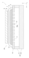
- FIG. 1 is a plan view of an electrolysis cell according to an embodiment.
- FIG. 2 is a cross-sectional view taken along line AA of FIG.
- FIG. 3 is a partially enlarged view of FIG. 2 .
- FIG. 1 is a plan view of an electrolysis cell 1 according to an embodiment of the present invention
- Fig. 2 is a cross-sectional view taken along line AA of Fig. 1.
- Electrolytic cell 1 is an example of an "electrochemical cell” according to the present invention. Electrolytic cell 1 is a so-called metal-supported electrolytic cell.
- the electrolytic cell 1 is formed in a plate shape extending in the X-axis and Y-axis directions.
- the electrolytic cell 1 is formed in a rectangular shape extending in the Y-axis direction when viewed in a plan view from the Z-axis direction perpendicular to the X-axis and Y-axis directions.
- the planar shape of the electrolytic cell 1 is not particularly limited, and may be a polygon other than a rectangle, an ellipse, a circle, etc.
- the electrolysis cell 1 includes a metal support 10, a cell body 20, and a flow path member 30.
- the metal support 10 supports the cell main body 20.
- the metal support 10 is formed in a plate shape.
- the metal support 10 may be in the shape of a flat plate or a curved plate.
- the metal support 10 only needs to be able to support the electrolysis cell 1, and there are no particular limitations on its thickness, but it can be, for example, 0.1 mm or more and 2.0 mm or less.
- the metal support 10 has a plurality of communication holes 11, a first main surface 12, and a second main surface 13.
- Each communication hole 11 penetrates the metal support 10 from the first main surface 12 to the second main surface 13.
- Each communication hole 11 opens to the first main surface 12 and the second main surface 13.
- the opening of each communication hole 11 on the first main surface 12 side is covered by a gas diffusion layer 5 described later.
- the opening of each communication hole 11 on the second main surface 13 side is connected to a flow path 30a described later.
- Each communication hole 11 can be formed by mechanical processing (e.g., punching), laser processing, or chemical processing (e.g., etching).
- each communication hole 11 is formed linearly along the Z-axis direction.
- each communication hole 11 may be inclined with respect to the Z-axis direction, and may not be linear.
- the communication holes 11 may be connected to each other.
- the first main surface 12 is provided on the opposite side to the second main surface 13.
- the cell main body 20 is disposed on the first main surface 12.
- the flow path member 30 is bonded to the second main surface 13.
- the metal support 10 is made of a metal material.
- the metal support 10 is made of an alloy material containing Cr (chromium).
- Examples of such metal materials include Fe-Cr alloy steel (stainless steel, etc.) and Ni-Cr alloy steel.
- Cr content in the metal support 10 can be 4% by mass or more and 30% by mass or less.
- the metal support 10 may contain Ti (titanium) and Zr (zirconium).
- the Ti content in the metal support 10 is not particularly limited, but may be 0.01 mol% or more and 1.0 mol% or less.
- the Al content in the metal support 10 is not particularly limited, but may be 0.01 mol% or more and 0.4 mol% or less.
- the metal support 10 may contain Ti as TiO2 (titania) and Zr as ZrO2 (zirconia).
- the metal support 10 may have an oxide film on its surface, which is formed by oxidation of the constituent elements of the metal support 10.
- a typical example of the oxide film is a chromium oxide film.
- the chromium oxide film covers at least a portion of the surface of the metal support 10.
- the chromium oxide film may also cover at least a portion of the inner wall surface of each communication hole 11.
- the cell body 20 is disposed on the metal support 10.
- the cell body 20 is supported by the metal support 10.
- the cell body 20 has a gas diffusion layer 5, a hydrogen electrode layer 6 (cathode), an electrolyte layer 7, a reaction prevention layer 8, and an oxygen electrode layer 9 (anode).
- the gas diffusion layer 5, hydrogen electrode layer 6, electrolyte layer 7, reaction prevention layer 8, and oxygen electrode layer 9 are stacked in this order in the Z-axis direction from the metal support 10 side.
- the gas diffusion layer 5, hydrogen electrode layer 6, electrolyte layer 7, and oxygen electrode layer 9 are required components, while the reaction prevention layer 8 is optional.
- the gas diffusion layer 5 is formed on the first main surface 12 of the metal support 10. In this embodiment, the gas diffusion layer 5 covers each of the communication holes 11 of the metal support 10. A part of the gas diffusion layer 5 may extend into each of the communication holes 11 of the metal support 10.
- the gas diffusion layer 5 is a porous body having electrical conductivity.
- the gas diffusion layer 5 has gas diffusibility.
- the gas diffusion layer 5 supplies the raw material gas supplied from each communication hole 11 to the hydrogen electrode layer 6, and discharges the product gas generated in the hydrogen electrode layer 6 to each communication hole 11.
- the gas diffusion layer 5 includes a conductive material.
- the conductive material that can be used include metal materials such as Ni (nickel) and Fe (iron), and conductive ceramic materials.
- the gas diffusion layer 5 may include a substrate supporting a conductive material.
- the substrate may be insulating.
- As the substrate YSZ, CSZ, ScSZ, GDC, SDC, (La, Sr) (Cr, Mn) O 3 , (La, Sr) TiO 3 , Sr 2 (Fe, Mo) 2 O 6 , (La, Sr) VO 3 , (La, Sr) FeO 3 , LDC (lanthanum doped ceria), LSGM (lanthanum gallate), and a mixed material of two or more of these may be used.
- the gas diffusion layer 5 may contain metal elements contained in the metal support 10. This is preferable because it improves the adhesion between the gas diffusion layer 5 and the metal support 10. Note that the conductive material described above is different from the metal elements contained in the metal support 10. Therefore, the conductive material contained in the gas diffusion layer 5 does not need to be contained in the metal support 10.
- the thickness of the gas diffusion layer 5 is not particularly limited, but can be, for example, 1 ⁇ m or more and 50 ⁇ m or less.
- the thickness means the thickness in the thickness direction of the cell body 20.
- the thickness direction is the direction perpendicular to the plane direction parallel to the first main surface 12 of the metal support 10.
- the plane direction is defined by an approximate straight line of the first main surface 12 obtained by the least squares method in the cross section of the metal support 10 along the Z-axis direction.
- the method for forming the gas diffusion layer 5 is not particularly limited, and may be a firing method, a spray coating method (thermal spraying, aerosol deposition, aerosol gas deposition, powder jet deposition, particle jet deposition, cold spray, etc.), a PVD method (sputtering, pulsed laser deposition, etc.), a CVD method, etc.
- the hydrogen electrode layer 6 is an example of a "first electrode layer” according to the present invention.
- the hydrogen electrode layer 6 is formed on the gas diffusion layer 5.
- the hydrogen electrode layer 6 is disposed between the gas diffusion layer 5 and the electrolyte layer 7.
- a source gas is supplied to the hydrogen electrode layer 6 from each of the communication holes 11 via the gas diffusion layer 5.
- the source gas contains at least H2O .
- the hydrogen electrode layer 6 produces H 2 from the source gas in accordance with the electrochemical reaction of water electrolysis shown in the following formula (1).
- Hydrogen electrode layer 6 H 2 O+2e ⁇ ⁇ H 2 +O 2 ⁇ (1)
- the hydrogen electrode layer 6 produces H 2 , CO, and O 2 ⁇ from the source gas in accordance with the co-electrochemical reactions shown in the following formulas (2), (3), and (4).
- Hydrogen electrode layer 6 CO 2 + H 2 O + 4e ⁇ ⁇ CO + H 2 + 2O 2 ⁇ (2) Electrochemical reaction of H 2 O: H 2 O + 2e ⁇ ⁇ H 2 + O 2 ⁇ (3) Electrochemical reaction of CO2 : CO2 + 2e- ⁇ CO + O2 -... (4)
- the hydrogen electrode layer 6 is a porous body having electrical conductivity.
- the hydrogen electrode layer 6 has gas diffusibility.
- the raw material gas is supplied to the hydrogen electrode layer 6 from the gas diffusion layer 5.
- the hydrogen electrode layer 6 discharges the product gas generated inside to the gas diffusion layer 5 side.
- the hydrogen electrode layer 6 includes a conductive material.
- a conductive material metal materials such as Ni (nickel) and Fe (iron), conductive ceramic materials, etc. can be used.
- Ni nickel
- Fe iron
- conductive ceramic materials etc.
- Ni also functions as a thermal catalyst that promotes the thermal reaction between the generated H 2 and CO 2 contained in the raw material gas to maintain an appropriate gas composition for methanation, reverse water gas shift reaction, etc.
- the conductive material When the conductive material is made of a metal material, the conductive material exists in an oxide state (e.g., NiO) in an oxidizing atmosphere and in a metallic state (e.g., Ni) in a reducing atmosphere. In this embodiment, it is assumed that the electrolytic cell 1 is exposed to a reducing atmosphere.
- an oxide state e.g., NiO
- a metallic state e.g., Ni
- the hydrogen electrode layer 6 includes an oxide ion conductive material.
- the oxide ion conductive material is an example of the "ion conductive material" according to the present invention.
- Examples of the oxide ion conductive material include YSZ, CSZ, ScSZ, GDC, SDC, (La, Sr) (Cr, Mn) O 3 , (La, Sr) TiO 3 , Sr 2 (Fe, Mo) 2 O 6 , (La, Sr) VO 3 , (La, Sr) FeO 3 , LDC, LSGM, and a mixed material of two or more of these.
- the hydrogen electrode layer 6 has a single-layer structure made of a single composition, but it may have a multi-layer structure made of different compositions.
- the thickness of the hydrogen electrode layer 6 is not particularly limited, but can be, for example, 1 ⁇ m or more and 500 ⁇ m or less.
- the method for forming the hydrogen electrode layer 6 is not particularly limited, and methods such as firing, spray coating, PVD, and CVD can be used.
- the electrolyte layer 7 is disposed between the hydrogen electrode layer 6 and the oxygen electrode layer 9.
- the reaction prevention layer 8 is disposed between the electrolyte layer 7 and the oxygen electrode layer 9, so that the electrolyte layer 7 is sandwiched between the hydrogen electrode layer 6 and the reaction prevention layer 8.
- the electrolyte layer 7 covers the hydrogen electrode layer 6 and also covers the area of the first main surface 12 of the metal support 10 that is exposed from the gas diffusion layer 5.
- the electrolyte layer 7 transfers O 2- generated in the hydrogen electrode layer 6 to the oxygen electrode layer 9.
- the electrolyte layer 7 is made of a dense material having oxide ion conductivity.
- the electrolyte layer 7 can be made of, for example, YSZ (yttria-stabilized zirconia, e.g., 8YSZ), GDC (gadolinium-doped ceria), ScSZ (scandia-stabilized zirconia), SDC (samarium-doped ceria), LSGM (lanthanum gallate), or the like.
- the porosity of the electrolyte layer 7 is not particularly limited, but can be, for example, 0.1% to 7%.
- the thickness of the electrolyte layer 7 is not particularly limited, but can be, for example, 1 ⁇ m to 100 ⁇ m.
- the method for forming the electrolyte layer 7 is not particularly limited, and methods such as baking, spray coating, PVD, and CVD can be used.
- reaction prevention layer 8 The reaction prevention layer 8 is disposed between the electrolyte layer 7 and the oxygen electrode layer 9. The reaction prevention layer 8 is disposed on the opposite side of the electrolyte layer 7 to the hydrogen electrode layer 6. The reaction prevention layer 8 prevents the constituent elements of the electrolyte layer 7 from reacting with the constituent elements of the oxygen electrode layer 9 to form a layer with high electrical resistance.
- the reaction prevention layer 8 is made of an oxide ion conductive material.
- the reaction prevention layer 8 can be made of GDC, SDC, etc.
- the porosity of the reaction prevention layer 8 is not particularly limited, but can be, for example, 0.1% to 50%.
- the thickness of the reaction prevention layer 8 is not particularly limited, but can be, for example, 1 ⁇ m to 50 ⁇ m.
- the method for forming the reaction prevention layer 8 is not particularly limited, and a baking method, a spray coating method, a PVD method, a CVD method, etc. can be used.
- the oxygen electrode layer 9 is an example of a "second electrode layer” according to the present invention.
- the oxygen electrode layer 9 is disposed on the opposite side of the hydrogen electrode layer 6 with respect to the electrolyte layer 7.
- the reaction prevention layer 8 is disposed between the electrolyte layer 7 and the oxygen electrode layer 9, and therefore the oxygen electrode layer 9 is connected to the reaction prevention layer 8. If the reaction prevention layer 8 is not disposed between the electrolyte layer 7 and the oxygen electrode layer 9, the oxygen electrode layer 9 would be connected to the electrolyte layer 7.
- the oxygen electrode layer 9 produces O 2 from O 2 ⁇ transferred from the hydrogen electrode layer 6 via the electrolyte layer 7 in accordance with the chemical reaction of the following formula (5).
- Oxygen electrode layer 9 2O 2 ⁇ ⁇ O 2 +4e ⁇ (5)
- the oxygen electrode layer 9 is a porous body having oxide ion conductivity and electrical conductivity, and may be made of a composite material of one or more of (La,Sr)(Co,Fe) O3 , (La,Sr) FeO3 , La(Ni,Fe) O3 , (La,Sr) CoO3 , and (Sm,Sr) CoO3 and an oxide ion conductive material (such as GDC).
- the porosity of the oxygen electrode layer 9 is not particularly limited, but can be, for example, 20% or more and 60% or less.
- the thickness of the oxygen electrode layer 9 is not particularly limited, but can be, for example, 1 ⁇ m or more and 100 ⁇ m or less.
- the method for forming the oxygen electrode layer 9 is not particularly limited, and a firing method, a spray coating method, a PVD method, a CVD method, etc. can be used.
- the flow path member 30 is joined to the second main surface 13 of the metal support 10.
- the flow path member 30 forms a flow path 30a between itself and the metal support 10.
- a source gas is supplied to the flow path 30a.
- the source gas supplied to the flow path 30a is supplied to the hydrogen electrode layer 6 of the cell main body 20 through each communication hole 11 of the metal support 10.
- the flow path member 30 can be made of, for example, an alloy material.
- the flow path member 30 may be made of the same material as the metal support 10. In this case, the flow path member 30 may be substantially integral with the metal support 10.
- the flow path member 30 has a frame body 31 and an interconnector 32.
- the frame body 31 is an annular member that surrounds the side of the flow path 30a.
- the frame body 31 is joined to the second main surface 13 of the metal support body 10.
- the interconnector 32 is a plate-shaped member for electrically connecting an external power source or another electrolysis cell in series with the electrolysis cell 1.
- the interconnector 32 is joined to the frame body 31.
- the frame body 31 and the interconnector 32 are separate members, but the frame body 31 and the interconnector 32 may be an integrated member.
- FIG. 3 is a partially enlarged view of FIG.
- the gas diffusion layer 5 has a plurality of first conductive particles 5a, a plurality of base particles 5b, and a plurality of first pores 5c.
- the plurality of first conductive particles 5a and the plurality of first pores 5c are essential components, while the plurality of base particles 5b is an optional component.
- the first conductive particles 5a are connected to each other. This forms a conductive path that extends in the thickness direction within the gas diffusion layer 5.
- the first conductive particles 5a are connected to each other at the neck portions L1.
- the neck portions L1 are formed by material transfer between the first conductive particles 5a that occurs when the gas diffusion layer 5 is heated.
- the base material particles 5b are connected to each other. This forms a skeleton that maintains the conductive path.
- the base material particles 5b are connected to each other at the neck portions L2.
- the neck portions L2 are formed by the transfer of material between the base material particles 5b that accompanies heating when forming the gas diffusion layer 5.
- the first pores 5c are connected to each other. This forms a gas flow path that spreads three-dimensionally within the gas diffusion layer 5.
- the first pores 5c are gaps between the first conductive particles 5a and the base material particles 5b.
- the hydrogen electrode layer 6 has a plurality of second conductive particles 6a, a plurality of ion conductive particles 6b, and a plurality of second pores 6c.
- the second conductive particles 6a are connected to each other. This forms a conductive path that extends in the thickness direction within the hydrogen electrode layer 6.
- the second conductive particles 6a are connected to each other at neck portions M1.
- the neck portions M1 are formed by material transfer between the second conductive particles 6a that accompanies heating when forming the hydrogen electrode layer 6.
- the ion conductive particles 6b are connected to each other. This forms an ion conductive path that spreads three-dimensionally within the hydrogen electrode layer 6.
- the ion conductive particles 6b are connected to each other at the neck portion M2.
- the neck portion M2 is formed by the transfer of material between the ion conductive particles 6b that accompanies heating when forming the hydrogen electrode layer 6.
- the second pores 6c are connected to each other. This forms a gas flow path that spreads three-dimensionally within the hydrogen electrode layer 6.
- the second pores 6c are gaps between the second conductive particles 6a and the ion conductive particles 6b.
- the average circle equivalent diameter of the first pores 5c in the gas diffusion layer 5 is smaller than the average circle equivalent diameter of the second pores 6c in the hydrogen electrode layer 6. That is, the gas diffusion layer 5 contains more small-diameter pores than the hydrogen electrode layer 6.
- the porosity of the gas diffusion layer 5 is greater than that of the hydrogen electrode layer 6. That is, the volume ratio of the gas flow path per unit volume of the gas diffusion layer 5 is greater than the volume ratio of the gas flow path per unit volume of the hydrogen electrode layer 6. This improves the gas diffusibility of the gas diffusion layer 5, so that the gas can be diffused in the gas diffusion layer 5 not only in the thickness direction but also in the surface direction. Therefore, the gas diffusion layer 5 can efficiently supply the raw material gas supplied from each communication hole 11 of the metal support 10 to the entire hydrogen electrode layer 6, and can efficiently discharge the product gas generated in the hydrogen electrode layer 6 from the entire hydrogen electrode layer 6 to each communication hole 11.
- the average equivalent circular diameter of a pore is the arithmetic mean of the equivalent circular diameters of each of the pores.
- the equivalent circular diameter of a pore is the diameter of a circle having the same area as the area of the pore that appears in a cross section along the thickness direction.
- the porosity of the gas diffusion layer 5 and the hydrogen electrode layer 6 can be obtained as follows. Since the method for measuring the porosity is common to each layer, the following explanation uses an example of obtaining the porosity of the gas diffusion layer 5.
- the electrolytic cell 1 is heated to 750°C and hydrogen is supplied to the gas diffusion layer 5 and the hydrogen electrode layer 6, thereby reducing the conductive material contained in the gas diffusion layer 5 and the hydrogen electrode layer 6.
- the temperature of the electrolytic cell 1 is lowered while still in the reducing atmosphere, and the electrolytic cell 1 is cut along the thickness direction (Z-axis direction) to expose the cross sections of the gas diffusion layer 5 and the hydrogen electrode layer 6.
- the cross section is precision machine polished and then ion milling processing is performed using Hitachi High-Technologies Corporation's IM4000.
- an FE-SEM Field Emission Scanning Electron Microscope
- an in-lens secondary electron detector is used to obtain an enlarged SEM image of the cross section of the gas diffusion layer 5 at a magnification (e.g., 5,000 to 30,000 times) sufficient to confirm the first conductive particles 5a, base particles 5b, and first pores 5c.
- the brightness of the SEM image is classified into 256 gradations, and the brightness difference of the first conductive particles 5a, the base particle 5b, and the first pores 5c is converted into three values.
- the first conductive particles 5a can be displayed in dark gray, the base particle 5b in light gray, and the first pores 5c in black.
- the SEM image is analyzed using image analysis software HALCON manufactured by MVTec (Germany) to obtain an analysis image in which the first pores 5c are highlighted.
- the total area of the first pores 5c (gas phase) is obtained from the analysis image, and the porosity in one analysis image is calculated by dividing the total area of the first pores 5c by the area of the entire analysis image.
- the above analysis is performed at five randomly selected locations on the same cross section of the gas diffusion layer 5, and the arithmetic mean value of the porosity calculated at the five locations is determined as the porosity of the gas diffusion layer 5.
- the number of first pores 5c per unit area of the gas diffusion layer 5 is greater than the number of second pores 6c per unit area of the hydrogen electrode layer 6. This allows gas to diffuse to every corner of the gas diffusion layer 5, thereby further improving the gas diffusivity of the gas diffusion layer 5.
- the number of pores can be obtained from the analysis image used to obtain the porosity.
- the average neck diameter between the first conductive particles 5a contained in the gas diffusion layer 5 is smaller than the average neck diameter between the second conductive particles 6a contained in the hydrogen electrode layer 6. This makes it easier to form a structure in the gas diffusion layer 5 that contains many small-diameter pores and has a large volume ratio of gas flow paths.
- the average neck diameter between the first conductive particles 5a is the arithmetic mean value of the neck diameters of the neck portions L1 between the first conductive particles 5a.
- the neck diameter of the neck portion L1 is the width of the narrowest part between the two first conductive particles 5a.
- the average neck diameter between the first conductive particles 5a can be obtained by taking the arithmetic mean of the neck diameters of the neck portions L1 at 10 locations randomly selected from the analysis image used to obtain the porosity.
- the average neck diameter between the first conductive particles 5a is not particularly limited, but can be, for example, 0.05 ⁇ m or more and 0.5 ⁇ m or less.
- the average neck diameter between the second conductive particles 6a is the arithmetic mean value of the neck diameters of the neck portions M1 between the second conductive particles 6a.
- the neck diameter of the neck portion M1 is the width of the narrowest part between the two second conductive particles 6a.
- the average neck diameter between the second conductive particles 6a can be obtained by taking the arithmetic mean of the neck diameters of the neck portions M1 at 10 locations randomly selected from the analysis image used to obtain the porosity.
- the average neck diameter between the second conductive particles 6a is not particularly limited, but can be, for example, 0.1 ⁇ m or more and 3 ⁇ m or less.
- the average neck diameter between the base material particles 5b contained in the gas diffusion layer 5 is smaller than the average neck diameter between the ion conductive particles 6b contained in the hydrogen electrode layer 6. This makes it easier to form a structure with many small pores and a large volume ratio of gas flow paths using the gas diffusion layer 5.
- the average neck diameter between base particles 5b is the arithmetic mean value of the neck diameters of the neck portions L2 between base particles 5b.
- the neck diameter of the neck portion L2 is the width of the narrowest part between two base particles 5b.
- the average neck diameter between base particles 5b can be obtained by taking the arithmetic mean of the neck diameters of the neck portions L2 at 10 locations randomly selected from the analysis image used to obtain the porosity.
- the average neck diameter between base particles 5b is not particularly limited, but can be, for example, 0.1 ⁇ m or less.
- the average neck diameter between the ion conductive particles 6b is the arithmetic mean value of the neck diameters of the neck portions M2 between the ion conductive particles 6b.
- the neck diameter of the neck portion M2 is the width of the narrowest part between the two ion conductive particles 6b.
- the average neck diameter between the ion conductive particles 6b can be obtained by taking the arithmetic mean of the neck diameters of the neck portions M2 at 10 locations randomly selected from the analysis image used to obtain the porosity.
- the average neck diameter between the ion conductive particles 6b is not particularly limited, but can be, for example, 1 ⁇ m or more and 3 ⁇ m or less.
- the openings of each communication hole 11 on the first main surface 12 side of the metal support 10 are covered by the gas diffusion layer 5, but this is not limited thereto.
- the gas diffusion layer 5 does not have to cover the openings of each communication hole 11 on the first main surface 12 side.
- the gas diffusion layer 5 has through holes communicating with each communication hole 11, so that gas can be supplied and exhausted more efficiently through the through holes.
- the electrolysis cell 1 has been described as an example of an electrochemical cell, but the electrochemical cell is not limited to the electrolysis cell.
- An electrochemical cell is a general term for an element in which a pair of electrodes are arranged so that an electromotive force is generated from an overall oxidation-reduction reaction in order to convert electrical energy into chemical energy, and an element for converting chemical energy into electrical energy. Therefore, the electrochemical cell includes, for example, a fuel cell that uses oxide ions or protons as a carrier.
- Electrolysis cell 10 Metal support 11 Through hole 12 First main surface 13 Second main surface 20 Cell body 5 Gas diffusion layer 5a First conductive particle 5b Base particle 5c First pore 5d Neck portion of first conductive particle 5e Neck portion of base particle 6 Hydrogen electrode layer 6a Second conductive particle 6b Ion conductive particle 6c Second pore 6d Neck portion of second conductive particle 6e Neck portion of ion conductive particle 7 Electrolyte layer 8 Reaction prevention layer 9 Oxygen electrode layer 30 Flow path member 30a Flow path
Landscapes
- Chemical & Material Sciences (AREA)
- Electrochemistry (AREA)
- Chemical Kinetics & Catalysis (AREA)
- Engineering & Computer Science (AREA)
- General Chemical & Material Sciences (AREA)
- Sustainable Development (AREA)
- Sustainable Energy (AREA)
- Life Sciences & Earth Sciences (AREA)
- Manufacturing & Machinery (AREA)
- Materials Engineering (AREA)
- Metallurgy (AREA)
- Organic Chemistry (AREA)
- Fuel Cell (AREA)
Abstract
Description
図1は、実施形態に係る電解セル1の平面図である。図2は、図1のA-A断面図である。
金属支持体10は、セル本体部20を支持する。金属支持体10は、板状に形成される。金属支持体10は、平板状であってもよいし、曲板状であってもよい。
セル本体部20は、金属支持体10上に配置される。セル本体部20は、金属支持体10によって支持される。セル本体部20は、ガス拡散層5、水素極層6(カソード)、電解質層7、反応防止層8、及び酸素極層9(アノード)を有する。
ガス拡散層5は、金属支持体10の第1主面12上に形成される。本実施形態においてガス拡散層5は、金属支持体10の各連通孔11を覆っている。ガス拡散層5の一部は、金属支持体10の各連通孔11の内側に入り込んでいてもよい。
水素極層6は、本発明に係る「第1電極層」の一例である。水素極層6は、ガス拡散層5上に形成される。水素極層6は、ガス拡散層5及び電解質層7の間に配置される。
・H2Oの電気化学反応:H2O+2e-→H2+O2-・・・(3)
・CO2の電気化学反応:CO2+2e-→CO+O2-・・・(4)
電解質層7は、水素極層6及び酸素極層9の間に配置される。本実施形態では、電解質層7及び酸素極層9の間に反応防止層8が配置されているので、電解質層7は、水素極層6及び反応防止層8の間に挟まれている。
反応防止層8は、電解質層7及び酸素極層9の間に配置される。反応防止層8は、電解質層7を基準として水素極層6の反対側に配置される。反応防止層8は、電解質層7の構成元素が酸素極層9の構成元素と反応して電気抵抗の大きい層が形成されることを抑制する。
酸素極層9は、本発明に係る「第2電極層」の一例である。酸素極層9は、電解質層7を基準として水素極層6の反対側に配置される。本実施形態では、電解質層7及び酸素極層9の間に反応防止層8が配置されているので、酸素極層9は反応防止層8に接続される。電解質層7及び酸素極層9の間に反応防止層8が配置されない場合、酸素極層9は電解質層7に接続される。
流路部材30は、金属支持体10の第2主面13に接合される。流路部材30は、金属支持体10との間に流路30aを形成する。流路30aには、原料ガスが供給される。流路30aに供給された原料ガスは、金属支持体10の各連通孔11を介して、セル本体部20の水素極層6に供給される。
図3は、図2の部分拡大図である。
以上、本発明の実施形態について説明したが、本発明はこれらに限定されるものではなく、本発明の趣旨を逸脱しない限りにおいて種々の変更が可能である。
上記実施形態において、金属支持体10の各連通孔11の第1主面12側の開口は、ガス拡散層5によって覆われることとしたが、これに限られない。ガス拡散層5は、各連通孔11の第1主面12側の開口を覆っていなくてもよい。この場合、ガス拡散層5には、各連通孔11に連なる貫通孔が形成されるので、当該貫通孔を介してより効率的なガスの給排を行うことができる。
上記実施形態では、電気化学セルの一例として電解セル1について説明したが、電気化学セルは電解セルに限られない。電気化学セルとは、電気エネルギーを化学エネルギーに変えるため、全体的な酸化還元反応から起電力が生じるように一対の電極が配置された素子と、化学エネルギーを電気エネルギーに変えるための素子との総称である。従って、電気化学セルには、例えば、酸化物イオン或いはプロトンをキャリアとする燃料電池が含まれる。
10 金属支持体
11 連通孔
12 第1主面
13 第2主面
20 セル本体部
5 ガス拡散層
5a 第1導電性粒子
5b 基材粒子
5c 第1気孔
5d 第1導電性粒子のネック部
5e 基材粒子のネック部
6 水素極層
6a 第2導電性粒子
6b イオン伝導性粒子
6c 第2気孔
6d 第2導電性粒子のネック部
6e イオン伝導性粒子のネック部
7 電解質層
8 反応防止層
9 酸素極層
30 流路部材
30a 流路
Claims (3)
- 主面に形成された複数の連通孔を有する金属支持体と、
前記主面上に配置されるセル本体部と、
を備え、
前記セル本体部は、
前記主面上に配置される導電性のガス拡散層と、
前記ガス拡散層上に配置される第1電極層と、
第2電極層と、
前記第1電極層及び前記第2電極層の間に配置される電解質層と、
を有し、
前記ガス拡散層は、複数の第1気孔を含み、
前記第1電極層は、複数の第2気孔を含んでおり、
前記複数の第1気孔の平均円相当径は、前記複数の第2気孔の平均円相当径より小さく、
前記ガス拡散層の気孔率は、前記第1電極層の気孔率より大きい、
電気化学セル。
- 単位面積当りにおける前記第1気孔の数は、前記単位面積当りにおける前記第2気孔の数より多い、
請求項1に記載の電気化学セル。
- 前記ガス拡散層は、複数の第1導電性粒子を含み、
前記第1電極層は、複数の第2導電性粒子を含んでおり、
前記第1導電性粒子どうしの平均ネック径は、前記第2導電性粒子どうしの平均ネック径より小さい、
請求項1又は2に記載の電気化学セル。
Priority Applications (2)
| Application Number | Priority Date | Filing Date | Title |
|---|---|---|---|
| JP2025509585A JPWO2024201997A1 (ja) | 2023-03-31 | 2023-03-31 | |
| PCT/JP2023/013527 WO2024201997A1 (ja) | 2023-03-31 | 2023-03-31 | 電気化学セル |
Applications Claiming Priority (1)
| Application Number | Priority Date | Filing Date | Title |
|---|---|---|---|
| PCT/JP2023/013527 WO2024201997A1 (ja) | 2023-03-31 | 2023-03-31 | 電気化学セル |
Publications (1)
| Publication Number | Publication Date |
|---|---|
| WO2024201997A1 true WO2024201997A1 (ja) | 2024-10-03 |
Family
ID=92904507
Family Applications (1)
| Application Number | Title | Priority Date | Filing Date |
|---|---|---|---|
| PCT/JP2023/013527 Ceased WO2024201997A1 (ja) | 2023-03-31 | 2023-03-31 | 電気化学セル |
Country Status (2)
| Country | Link |
|---|---|
| JP (1) | JPWO2024201997A1 (ja) |
| WO (1) | WO2024201997A1 (ja) |
Citations (4)
| Publication number | Priority date | Publication date | Assignee | Title |
|---|---|---|---|---|
| WO2016043328A1 (ja) * | 2014-09-19 | 2016-03-24 | 大阪瓦斯株式会社 | 電気化学素子、固体酸化物形燃料電池セル、およびこれらの製造方法 |
| WO2017010435A1 (ja) * | 2015-07-16 | 2017-01-19 | 住友電気工業株式会社 | 燃料電池 |
| JP2021163764A (ja) * | 2020-03-31 | 2021-10-11 | 大阪瓦斯株式会社 | 電気化学素子、電気化学モジュール、電気化学装置、エネルギーシステム、固体酸化物形燃料電池、固体酸化物形電解セル |
| WO2023013205A1 (ja) * | 2021-08-05 | 2023-02-09 | 株式会社デンソー | 電気化学セル |
-
2023
- 2023-03-31 JP JP2025509585A patent/JPWO2024201997A1/ja active Pending
- 2023-03-31 WO PCT/JP2023/013527 patent/WO2024201997A1/ja not_active Ceased
Patent Citations (4)
| Publication number | Priority date | Publication date | Assignee | Title |
|---|---|---|---|---|
| WO2016043328A1 (ja) * | 2014-09-19 | 2016-03-24 | 大阪瓦斯株式会社 | 電気化学素子、固体酸化物形燃料電池セル、およびこれらの製造方法 |
| WO2017010435A1 (ja) * | 2015-07-16 | 2017-01-19 | 住友電気工業株式会社 | 燃料電池 |
| JP2021163764A (ja) * | 2020-03-31 | 2021-10-11 | 大阪瓦斯株式会社 | 電気化学素子、電気化学モジュール、電気化学装置、エネルギーシステム、固体酸化物形燃料電池、固体酸化物形電解セル |
| WO2023013205A1 (ja) * | 2021-08-05 | 2023-02-09 | 株式会社デンソー | 電気化学セル |
Also Published As
| Publication number | Publication date |
|---|---|
| JPWO2024201997A1 (ja) | 2024-10-03 |
Similar Documents
| Publication | Publication Date | Title |
|---|---|---|
| JP7637833B1 (ja) | 電気化学セル | |
| US20240360575A1 (en) | Electrochemical cell | |
| JP7649810B2 (ja) | 電気化学セル | |
| WO2024201893A1 (ja) | 電気化学セル | |
| US20240332565A1 (en) | Electrochemical cell | |
| JP7641449B2 (ja) | 電気化学セル | |
| JP7625134B2 (ja) | 電気化学セル | |
| JP7698795B2 (ja) | 電気化学セル | |
| JP7394190B1 (ja) | 電気化学セル | |
| JP7657379B1 (ja) | 電気化学セル | |
| JP7659705B1 (ja) | 電気化学セル | |
| JP7657365B2 (ja) | 電気化学セル | |
| JP7696497B2 (ja) | 電気化学セル | |
| JP7604715B2 (ja) | 電気化学セル | |
| JP7577244B2 (ja) | 電気化学セル | |
| JP7649929B2 (ja) | 電気化学セル | |
| US20250300194A1 (en) | Inter-connector and electrochemical cell | |
| US20250297376A1 (en) | Inter-connector and electrochemical cell | |
| WO2024201938A1 (ja) | 電気化学セル、金属支持体、及び金属支持体の製造方法 | |
| JP2024044532A (ja) | 電気化学セル | |
| WO2024201640A1 (ja) | 電気化学セル | |
| WO2024143292A1 (ja) | 電気化学セル | |
| WO2025141900A1 (ja) | 電気化学セル | |
| WO2024122286A1 (ja) | 電気化学セル | |
| JP2024122245A (ja) | 電気化学セル |
Legal Events
| Date | Code | Title | Description |
|---|---|---|---|
| 121 | Ep: the epo has been informed by wipo that ep was designated in this application |
Ref document number: 23930632 Country of ref document: EP Kind code of ref document: A1 |
|
| ENP | Entry into the national phase |
Ref document number: 2025509585 Country of ref document: JP Kind code of ref document: A |
|
| WWE | Wipo information: entry into national phase |
Ref document number: 2025509585 Country of ref document: JP |
|
| NENP | Non-entry into the national phase |
Ref country code: DE |
|
| 122 | Ep: pct application non-entry in european phase |
Ref document number: 23930632 Country of ref document: EP Kind code of ref document: A1 |