WO2024201879A1 - メンテナンス支援システム - Google Patents
メンテナンス支援システム Download PDFInfo
- Publication number
- WO2024201879A1 WO2024201879A1 PCT/JP2023/013126 JP2023013126W WO2024201879A1 WO 2024201879 A1 WO2024201879 A1 WO 2024201879A1 JP 2023013126 W JP2023013126 W JP 2023013126W WO 2024201879 A1 WO2024201879 A1 WO 2024201879A1
- Authority
- WO
- WIPO (PCT)
- Prior art keywords
- maintenance
- unit
- work
- support system
- display
- Prior art date
- Legal status (The legal status is an assumption and is not a legal conclusion. Google has not performed a legal analysis and makes no representation as to the accuracy of the status listed.)
- Ceased
Links
Images









Classifications
-
- H—ELECTRICITY
- H05—ELECTRIC TECHNIQUES NOT OTHERWISE PROVIDED FOR
- H05K—PRINTED CIRCUITS; CASINGS OR CONSTRUCTIONAL DETAILS OF ELECTRIC APPARATUS; MANUFACTURE OF ASSEMBLAGES OF ELECTRICAL COMPONENTS
- H05K13/00—Apparatus or processes specially adapted for manufacturing or adjusting assemblages of electric components
- H05K13/08—Monitoring manufacture of assemblages
- H05K13/0895—Maintenance systems or processes, e.g. indicating need for maintenance
Definitions
- the present invention relates to a maintenance support system that supports the maintenance of various work sections of a component mounting system that is equipped with various work sections for producing component mounting boards.
- Component mounting devices that mount electronic components (hereafter referred to as components) on a board to manufacture component-mounted boards are well known.
- Component mounting devices are made up of working sections such as a transport mechanism that transports and positions the board, a feeder that supplies components, a nozzle that sucks and holds the components, a mounting head equipped with the nozzle, and a head drive mechanism that moves the mounting head.
- Patent Document 1 discloses a malfunction detection system that transmits data such as component pickup errors, supply errors, and pickup position deviation amounts from the component mounting device to a management computer, and identifies and notifies the malfunctioning part (feeder, mounting head, nozzle) based on the data.
- This malfunction detection system has the advantage that it makes it possible to quickly identify the malfunctioning area and perform maintenance.
- this malfunction detection system is a system that identifies the malfunctioning area, and does not incorporate any measures to allow maintenance to be carried out efficiently and rationally in cases where malfunctions occur in multiple areas at the same time. Therefore, there is room for improvement in this area.
- the present invention aims to provide a maintenance support system that enables efficient and rational maintenance in cases where malfunctions occur simultaneously in multiple locations in a component mounting system equipped with a work unit for producing component mounted boards.
- the maintenance support system is a maintenance support system for a component mounting system including a plurality of work units that perform work for producing component mounting boards, and includes a display unit that displays maintenance items for those work units that require maintenance among the plurality of work units, a display control unit that controls the display unit, and an arithmetic processing unit that executes a process of obtaining parameter data indicating the work accuracy of the work units for each unit period and a process of detecting work units whose work accuracy has decreased based on the data as work units that are subject to maintenance, and the display control unit controls the display method and/or display content of the maintenance items for the target work units so that maintenance of the target work units is given priority over maintenance of other work units.
- FIG. 1 is a block diagram of a component mounting system equipped with a maintenance support system according to the present invention.
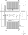
- FIG. 2 is a plan view of a mounting device provided in the component mounting system.
- FIG. 3 is a front view showing a head unit of the mounting device.
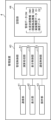
- FIG. 4 is a block diagram showing the configuration of the management device.
- FIG. 5 is a flow diagram of the maintenance support process.
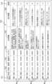
- FIG. 6 is a diagram illustrating an example of the maintenance support information.
- FIG. 7 is a diagram showing an example of a condition setting screen for trend analysis processing.
- FIG. 8 is an explanatory diagram of the trend analysis process.
- FIG. 9 is an explanatory diagram of the trend analysis process.
- FIG. 10 is an explanatory diagram of the trend analysis process.
- FIG. 1 is a block diagram of a component mounting system equipped with a maintenance support system according to the present invention.
- FIG. 2 is a plan view of a mounting device provided in the component mounting system.
- FIG. 3 is
- FIG. 11 is a diagram showing an example of a condition setting screen for the demand level determination process.
- FIG. 12 is a diagram showing an example of updating the maintenance support information.
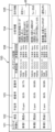
- FIG. 13 is a diagram showing another example of the maintenance support information.
- FIG. 14 is a diagram showing another example of the maintenance support information.
- FIG. 1 is a block diagram showing a component mounting system 1 equipped with a maintenance support system according to the present invention.
- the component mounting system 1 includes a mounting device 2, an inspection device 3, and a management device 4 connected to the mounting device 2 and the inspection device 3 so that data communication is possible.
- the mounting device 2 is a device that mounts (mounts) electronic components (hereinafter referred to as "components") on a substrate P such as a printed wiring board.
- the inspection device 3 is a device that inspects the mounting state of the components mounted on the substrate P by the mounting device 2.
- FIG. 2 is a plan view showing the mounting device 2
- FIG. 3 is a front view showing a head unit 15 (described later) of the mounting device 2.
- the mounting device 2 includes a base 10, a conveyor 12, a component supply unit 14, a head unit 15, and an imaging unit 13.
- the conveyor 12 is a transport line for the substrate P.
- the conveyor 12 transports the substrate P from outside the machine to a predetermined work position, and after mounting work, transports the substrate P from the work position to outside the machine.
- the position of the substrate P shown in FIG. 2 is the work position.
- the component supply units 14 are areas for supplying components, and are provided on both sides of the conveyor 12.
- the component supply units 14 are provided with multiple feeders 14a, and components are supplied by each feeder 14a.
- each component supply unit 14 is provided with a tape feeder that supplies components by unwinding a tape containing components at regular intervals.
- Various types of feeders other than tape feeders may also be provided in the component supply units 14.
- the head unit 15 picks up components from the feeder 14a in the component supply unit 14, moves to a working position, and performs a component mounting process to mount the components on the board P. As shown in FIG. 3, the head unit 15 has multiple mounting heads 16, each equipped with a nozzle 16a at its tip (lower end). The nozzle 16a is a member that picks up the components supplied by the feeder 14a.
- the nozzle 16a can be connected to either a negative pressure generator, a positive pressure generator, or the atmosphere via an electric switching valve. Supplying negative pressure to the nozzle 16a enables the nozzle 16a to suck and hold a component, and then supplying positive pressure releases the sucked and held component.
- the passage between the nozzle 16a of each mounting head 16 and each of the electric switching valves is equipped with a suction level sensor (not shown). The suction level sensor detects the suction level of the component, specifically the negative pressure level in the passage.
- the mounting head 16 is capable of moving up and down (raising and lowering) and rotating around an axis (moving in the R direction), and is driven by a motor not shown.
- the mounting head 16 descends to a predetermined component pickup position, picks up and holds the component with the nozzle 16a, and then rises.
- the mounting head 16 descends to the component mounting position above the board P and releases the component onto the board P by releasing the component from the suction hold. This allows the component to be mounted at the target mounting position set on the board P.
- the head unit 15 can move horizontally in the space above between the component supply unit 14 and the substrate P at the work position by operation of the head unit drive mechanism 17.
- the head unit drive mechanism 17 comprises fixed rails 18 each fixed to a pair of elevated frames installed on the base 10, a beam member 19 that moves in the Y direction along the fixed rails 18, and a unit support part (not shown) that moves in the X direction along the beam member 19.
- the head unit 15 is attached to this unit support part.
- the beam member 19 and the unit support member each move by the driving force of a motor. The movement of the beam member 19 and the unit support member causes the head unit 15 to move in the X and Y directions.
- the imaging unit 13 includes a first imaging unit 13a and a second imaging unit 13b. Both the first imaging unit 13a and the second imaging unit 13b are imaging cameras equipped with imaging elements.
- the first imaging unit 13a is installed on the base 10 between the component supply unit 14 and the conveyor 12. After the nozzle 16a of each mounting head 16 has adsorbed and held a component, the first imaging unit 13a images the component adsorbed and held by the nozzle 16a from below when the head unit 15 moves from the component supply unit 14 to above the board P at the work position.
- the image thus obtained is an image that makes it possible to confirm the processing state of the component adsorption process, such as the attitude of the component adsorbed by the nozzle 16a and the amount of deviation of the adsorption position of the component relative to the nozzle 16a, in addition to the component adsorption failure by the nozzle 16a.
- a component adsorption failure is a processing state in which the nozzle 16a is unable to adsorb and hold a component supplied by the feeder 14a, or a component is adsorbed and held once but then falls off.
- the second imaging unit 13b is disposed in the head unit 25.
- the second imaging unit 13b images the marks from above in order to recognize the various marks affixed to the top surface of the board P placed at the work position.
- the recognition of the marks on the board P by the second imaging unit 13b detects the amount of positional deviation from the origin coordinates of the board P.
- the second imaging unit 13b further images the component supply position of the feeder 14a before the nozzle 16a of each mounting head 16 sucks and holds the component.
- the image obtained in this way is an image that makes it possible to check for component supply errors and the amount of deviation in the supply position as the processing status of the component supply process.
- the mounting device 2 is equipped with a mounting control unit 20 that comprehensively controls the operation of each part, such as the conveyor 12, the feeder 14a, the head unit 15 (head unit drive mechanism 17), and the mounting head 16.
- the mounting control unit 20 controls each part, such as the head unit 15, to execute a component mounting process for mounting components on the substrate P, and also executes various calculation processes required for this component mounting process.
- the mounting control unit 20 also transmits mounting history data D1 (see FIG. 1) to the management device 4 periodically or based on a request signal input from the management device 4.
- This mounting history data D1 includes production board data D11, setup data D12, pickup position deviation amount data D13, pickup level data D14, pickup state data D15, component supply state data D16, maintenance data D17, etc.
- the production board data D11 is data relating to the type and number of boards produced.
- the setup data D12 is data relating to the nozzle 16a, mounting head 16, and feeder 14a used in production.
- the suction position deviation amount data D13 is data indicating the deviation amount of the component suction position relative to the nozzle 16a.
- the suction level data D14 is data indicating the suction level (negative pressure level) when the nozzle 16a picks up a component.
- the suction status data D15 is data indicating suction errors and suction posture by the nozzle 16a.
- the component supply status data D16 is data indicating component supply errors and the deviation amount of the supply position by the feeder 14a.
- the maintenance data D17 is data relating to the history of maintenance that has been performed.
- the mounting history data D1 includes various data acquired by the mounting device 2 and useful for the maintenance support process executed by the management device 4, which will be described later.
- the inspection device 3 is equipped with a conveyor, an inspection head, and a head drive mechanism.
- the conveyor carries the board P, which has completed component mounting processing by the mounting device 2, into a prescribed working position, and after the inspection processing is completed, carries the board P out of the machine from the working position.
- the inspection head is equipped with an imaging section consisting of, for example, an imaging camera, and can be moved horizontally in the space above the substrate P at the work position by operating the head drive mechanism.
- the inspection head images each component mounting position while moving above the substrate P.
- the images obtained in this way are images that make it possible to check for component mounting errors as well as, for example, the posture of the mounted components and the amount of deviation in the mounting position.
- the inspection device 3 is equipped with an inspection control unit 30 that controls the overall operation of the inspection device 3.
- the inspection control unit 30 detects component mounting errors, the attitude of the mounted components, and the amount of deviation in the mounting position, as described above, based on the images acquired by the inspection head (imaging unit).
- the inspection control unit 30 transmits the inspection data D2 (see FIG. 1) of each board P to the management device 4 periodically or upon input of a request signal from the management device 4.
- this inspection data D2 includes various data acquired by the inspection device 3 and useful in the maintenance support process executed by the management device 4, which will be described later.
- the management device 4 is configured, for example, by a personal computer that is connected to the mounting device 2 and the inspection device 3 so that data communication is possible.
- the management device 4 has a function of comprehensively managing the component mounting system 1, and mainly supports the maintenance of the mounting device 2 and the inspection device 3. In other words, the management device 4 functions as the maintenance support system of the present invention.
- FIG. 4 is a block diagram showing the configuration of the management device.
- the management device 4 includes a management control unit 40, a communication unit 41, a display unit 42, an operation unit 43, and a storage unit 44.
- the communication unit 41 is an interface for performing data communication with the mounting device 2 and the inspection device 3.
- the communication unit 41 acquires mounting history data D1 input from the mounting device 2 and inspection data D2 input from the inspection device 3.
- the memory unit 44 stores the mounting history data D1 and the inspection data D2 acquired by the communication unit 41 as management data DM.
- the management data DM also includes production plan information DM1 for component mounting boards and mounted component information DM2.
- the production plan information DM1 is information such as the type and number of component mounting boards to be produced, and the type and number of components to be mounted on the component mounting boards.
- the mounted component information DM2 is various information about the components used in the production of component mounting boards, such as the type (name), size, unit price, and usage history.
- the mounting history data D1 stored as the management data DM includes the maintenance data D17. Therefore, in this example, the storage unit 44 corresponds to the "history information storage unit" of the present invention.
- the display unit 42 is configured, for example, with a liquid crystal display.
- the display unit 42 displays management information for the component mounting system 1. This management information includes the maintenance support information described below for supporting maintenance.
- the display operation of the display unit 42 is controlled by the management control unit 40.
- the operation unit 43 (corresponding to the "operation input unit” of the present invention) is composed of a keyboard, a mouse, or a touch panel provided on the display unit 42.
- the operation unit 43 accepts input operations of various commands and settings for the management control unit 40.
- the management control unit 40 executes various processes related to the management of the component mounting system 1 in response to commands input to the operation unit 43.
- the management control unit 40 is composed of a CPU, ROM, RAM, etc., and includes an arithmetic processing unit 51, a display control unit 52, and a communication control unit 53 as functional components for executing the maintenance support process described above.
- the communication control unit 53 controls the communication unit to control data communication between the mounting device 2 and the inspection device 3.
- the calculation processing unit 51 executes maintenance support processing based on the mounting history data D1 input from the mounting device 2, the inspection data D2 input from the inspection device, and the management data DM, and executes various calculation processes associated with the maintenance support processing.
- the display control unit 52 controls the display unit 42 to display various information according to the processing results of the calculation processing unit 51.
- the component mounting system 1 (the mounting device 2 and the inspection device 3) includes a plurality of "working units" for producing component mounting boards.
- the conveyor 12, the feeder 14a, the head unit 15 (head unit driving mechanism 17), the mounting head 16, the nozzle 16a, and the like correspond to the working units.
- the inspection device 3 the conveyor and the inspection head (head driving mechanism) and the like correspond to the working units. If a malfunction occurs in these working units and the work accuracy decreases, the mounting accuracy of the components by the mounting device 2 and the inspection accuracy by the inspection device 3 decrease.
- the maintenance support process is a process of detecting (identifying) a working unit whose work accuracy has decreased based on the mounting history data D1, the inspection data D2, and the management data DM described above, and displaying information (maintenance support information) that supports the maintenance of the working unit to be performed preferentially, that is, to be performed preferentially over regular maintenance that is scheduled periodically, on the display unit 42.
- the conveyor 12, the feeder 14a, and the like may be referred to as a working unit (working unit Wp) as described.
- FIG. 5 is a flow diagram showing the flow of the maintenance support process.
- the maintenance support process proceeds along the steps of (1) data acquisition process, (2) trend analysis process, (3) work unit detection process, (4) importance determination process, and (5) display process. Then, maintenance support information 100 as shown in FIG. 6 is displayed on the display unit 42.
- the maintenance support information 100 is in list format, displaying the maintenance items M of the work unit Wp that requires maintenance in a vertical order, with the maintenance items M of higher importance displayed at the top. The worker performs maintenance by accessing this maintenance support information 100. This maintenance support information 100 will be explained in detail later in "4. Display processing".
- the data acquisition process is executed by the communication control unit 53.
- the communication control unit 53 controls the communication unit 41 to acquire mounting history data D1 from the mounting device 2 and inspection data D2 from the inspection device 3, and cumulatively stores the data D1 and D2 in the storage unit 44.
- the data D1 and D2 are acquired, for example, for each set number of sheets or for each set period.
- the trend analysis process is executed by the calculation processing unit 51. Immediately after a preset unit period U has elapsed, the calculation processing unit 51 refers to the mounting history data D1 and the inspection data D2 stored in the storage unit 44, and obtains a predetermined analysis parameter for the unit period U based on the data D1 and D2.
- Analysis parameters are parameters for evaluating the work accuracy of the work unit Wp.
- “Number of inspection failures,” “Inspection defect rate,” “Number of component pickup errors,” “Component pickup rate,” “Number of component mounting errors,” “Component mounting rate,” “Component pickup accuracy,” “Component mounting accuracy,” and “Negative pressure level” are parameters that can be used to evaluate work accuracy and are included in the analysis parameters. Note that “mounting” is synonymous with “mounting.”
- the unit period U is defined by the number of operating hours (days) or the number of pieces produced.
- the unit period U may also be defined by the number of operations performed by each work unit Wp.
- the unit period U can be defined by the number of component pick-up operations.
- the unit period U can be defined by the number of component mounting operations. In the following explanation, unless otherwise specified, the unit period U will be described as "1 day (24 hours)".
- the calculation processing unit 51 executes a process of analyzing the trend (progression) of each analysis parameter from the obtained analysis parameter data and past analysis parameter data. Specifically, it analyzes whether the value of the analysis parameter is tending to worsen.
- the trend analysis process is performed based on preset trend analysis conditions. These trend analysis conditions can be set by the operator using the analysis condition setting screen shown in Figure 7.
- FIG. 7 shows an example of an analysis condition setting screen for trend analysis processing.
- the operator operates the operation unit 43 to input the number of days (i.e., the number of unit periods U) and the like for each setting item field displayed on the analysis condition setting screen 200.
- This sets the trend analysis conditions. In this way, the freedom of trend analysis is improved by being able to arbitrarily set trend analysis conditions.
- the analysis condition setting screen 200 displays, as setting item columns, for example, a continuing deterioration analysis setting column 201, a post-maintenance analysis setting column 202, a focused part setting column 203, and a trend analysis setting column 204.
- the conditions for trend analysis based on the analysis parameters as described above are set in the trend analysis setting field 204.
- the trend analysis setting field 204 is a field for setting the reference values for trend analysis of the analysis parameters.
- the values for "threshold”, “significant difference”, “number of consecutive days of deterioration”, and “predicted date” are set for each analysis parameter (defective rate, pick-up rate, pick-up accuracy, attachment accuracy, and negative pressure level).
- the "threshold” is set to 10 ppm, the "significant difference” to 5%, the "number of consecutive days of deterioration” to 5 days, and the “predicted date” to 5 days.
- specific numerical values are set for the "threshold", “significant difference”, “number of consecutive days of deterioration", and "predicted date” as shown in the figure.
- Figure 8 is an explanatory diagram of the trend analysis process.
- the figure shows in a graph the daily (unit period U) changes in an analysis parameter (e.g., "adsorption rate"), where the lower the value, the lower the evaluation of the work accuracy.
- an analysis parameter e.g., "adsorption rate”
- the calculation processing unit 51 analyzes the trends in the analysis parameters for a specified analysis period.
- the analysis period is specified by the number of days (the number of unit periods U). In the illustrated example, the analysis period is five days.
- the calculation processing unit 51 determines the analysis parameters for that fifth day, and analyzes the trends based on the data of the past analysis parameters for the five days including that fifth day. Specifically, it determines whether the analysis parameters are showing a worsening trend based on the trends in the data of the analysis parameters from the first day (first period) to the fifth day (fifth period).
- the calculation processing unit 51 determines that the analysis parameter is tending to deteriorate.
- the calculation processing unit 51 determines that the analysis parameter is on a worsening trend. For example, assuming that the analysis parameter in FIG. 8 is "defective rate,” the figure shows that the "defective rate” deteriorates for five consecutive days from the first day to the fifth day. Since the setting value for the "number of consecutive days of deterioration" for the "defective rate” is five days, in this case the calculation processing unit 51 determines that the "defective rate” is on a worsening trend.
- the calculation processing unit 51 may set a regression line L for the values of the analysis parameters for those five days as shown in FIG. 8, and determine the trend of the analysis parameters based on the regression line L. In other words, it may determine that the analysis parameters are deteriorating linearly.
- the calculation processing unit 51 determines that the analysis parameter is tending to deteriorate. For example, as shown in FIG.
- the calculation processing unit 51 determines that the analysis parameter is tending to deteriorate. In this case, the calculation processing unit 51 can set the regression line L as shown in FIG. 9, and estimate the value of the analysis parameter on the "prediction date" based on the regression line L.
- the calculation processing unit 51 will determine that the analysis parameter is tending to deteriorate.
- the calculation processing unit 51 calculates the analysis parameters for the sixth day and analyzes their trends based on the past analysis parameter data for the five days including the sixth day. Specifically, it analyzes whether the analysis parameters are showing a worsening trend based on the trends in the analysis parameter data from the second day to the sixth day. Thereafter, in the same manner, it calculates the analysis parameters for the next five days every day and analyzes whether the analysis parameters are showing a worsening trend based on the trends in the analysis parameters.
- the continuous deterioration analysis setting field 201 is a field for setting conditions for detecting whether a maintenance item M for a specific work unit Wp appears multiple times at the top of the maintenance support information 100 (see FIG. 6).
- the number of days for which the continuous deterioration analysis will be performed and the threshold value for the continuous deterioration period can be set.
- the period for which the continuous deterioration analysis will be performed is set to "5 days” and the threshold value is set to "3 days".
- the calculation processing unit 51 will analyze a period of five consecutive days, and if a maintenance item M for a specific work unit Wp appears at the top of the maintenance support information 100 for three or more days, it will determine that the work accuracy of that work unit Wp is continually deteriorating.
- the post-maintenance analysis setting field 202 is a field for setting conditions for detecting whether a working part Wp for which maintenance has been performed appears again at the top of the maintenance support information 100 as a maintenance target.
- the number of days can be set as the detection period. In the example of FIG. 7, it is set to "5 days.”
- the calculation processing unit 51 determines that the work accuracy of the working part Wp has deteriorated.
- FIG. 10 An example is shown in Figure 10.
- errors occur in the working unit Wp from the first day (first period) to the second day (second period). Maintenance is performed at the end of the third day (third period), but after the maintenance, errors occur again on the fourth day (fourth period) and fifth day (fifth period). Therefore, if the working unit Wp appears again at the top of the maintenance support information 100 as a maintenance target within five days, the calculation processing unit 51 determines that the work accuracy of the working unit Wp has deteriorated.
- the noted part setting field 203 is a field for setting noted parts, and this setting field is configured with, for example, check boxes. Parts that have been registered in advance and new parts that have not been used in the past are included in noted parts. If a noted part is set in the noted part setting field 203 even though the part is not a working part Wp, the calculation processing unit 51 determines that the quality of the shape, etc. of the noted part is deteriorating if the data of the analysis parameters related to the set noted part is deteriorating.
- Working unit detection process When an analysis parameter showing a worsening tendency is found in the trend analysis process (trend analysis based on the analysis parameter), the calculation processing unit 51 executes a working unit detection process for identifying a working unit Wp requiring maintenance (hereinafter referred to as a target working unit Wp). This working unit detection process is executed based on a calculation process in accordance with a predetermined judgment algorithm that is statistically determined based on the analysis parameter showing a worsening tendency and other analysis parameters related to the analysis parameter, the mounting history data D1, and the inspection data D2 stored in the storage unit 44.
- the calculation processing unit 51 detects, as the target work unit Wp, a work unit Wp whose work accuracy has been determined to be continually deteriorating by trend analysis based on the conditions set in the continuous deterioration analysis setting field 201, that is, a work unit Wp that appears multiple times at the top of the maintenance support information 100.
- the calculation processing unit 51 also detects, as the target work unit Wp, a work unit Wp whose work accuracy has been determined to be declining by trend analysis based on the conditions set in the post-maintenance analysis setting field 202, that is, a work unit Wp that is being subject to maintenance again after maintenance.
- the calculation processing unit 51 detects the component of interest itself as a maintenance target.
- the component of interest itself is regarded as the target work part Wp and detected as a maintenance target. This makes it possible to confirm that the deterioration of the analysis parameter data is caused by the component.
- the calculation processing unit 51 further executes an importance determination process for determining the "importance" of the maintenance of the target working unit Wp.
- the importance is information that serves as an index for determining the priority level of the maintenance of the target working unit Wp.
- the calculation processing unit 51 executes this importance determination process based on preset importance determination conditions.
- FIG. 11 shows an example of an importance setting screen for setting the importance determination conditions.
- the operator operates the operation unit 43 to input the number of days (the number of unit periods U) and specific numerical values in the setting item fields displayed on the importance setting screen 300. In this way, the importance determination conditions are set.
- the importance setting screen 300 displays five setting item columns, for example, a continuing deterioration analysis setting column 301, a post-maintenance analysis setting column 302, a focused part setting column 303, a loss cost setting column 304, and a trend analysis setting column 305.
- These setting columns 301 to 305 correspond to the setting columns 201 to 204 of the analysis condition setting screen 200 described above, except for the loss cost setting column 304.
- Each setting item can be set to one of three levels: "A,” “B,” or “C,” in descending order of importance. Note that the number of levels that can be set can be two, or four or more.
- the continuous deterioration analysis setting field 301 is a field for setting the importance according to the number of days the target work part Wp has been displayed in the top of the maintenance support information 100 multiple times. In the example of FIG. 11, four or more days is set to "A", and three or more days is set to "B".
- the setting for "C” is "none", which indicates that it has not been set. In other words, if the target work part Wp has been displayed in the top of the maintenance support information 100 for four or more days, the importance of the maintenance of the target work part Wp is set to "A", and if it has been displayed for three or more days (3 days), the importance of the maintenance of the target work part Wp is set to "B". Since the importance of "C” has not been set, the importance of "C” is not set.
- the post-maintenance analysis setting field 302 is a field for setting the importance level when the target working part Wp is detected as a maintenance target again after maintenance.
- the importance level is set based on how many days ago the maintenance was performed, counting back from the day the target working part Wp was detected as a maintenance target again. In the example of FIG. 11, the importance level "A" is set to one day before the detection date. In other words, if the target working part Wp is detected as a maintenance target again the day after maintenance, the importance level of the maintenance of the target working part Wp is set to "A".
- the attention part setting field 303 is a field for setting the importance when the attention part set in the attention part setting field 203 on the analysis condition setting screen 200 is detected as a target for confirmation (maintenance).
- the setting is performed by selecting the importance level for each part from "A" to "C.”
- the importance is set to "A” for both parts that have been registered in advance as attention parts and new parts.
- the attention part is considered to be the target work part Wp and detected as a target for confirmation, the importance is set to "A.”
- the loss cost setting field 304 is a field for setting the importance of maintenance of the target working part Wp based on the loss cost caused by the decline in the work accuracy of the target working part Wp.
- the importance is set to "A" when the loss cost is 50,000 yen or more, and "B" when the loss cost is between 5,000 yen and 50,000 yen.
- the loss cost caused by the decline in the work accuracy of the target working part Wp such as the cost of discarded parts, is 50,000 yen or more
- the importance of maintenance of the target working part Wp is set to "A".
- the trend analysis setting field 305 is a field for setting the importance according to the tendency of deterioration of the analysis parameters (defective rate, adsorption rate, adsorption accuracy, mounting accuracy, and negative pressure level) described above.
- the importance can be set from three perspectives: “threshold”, “significant difference”, and “number of consecutive days of deterioration”.
- the importance of each of "threshold”, “significant difference”, and “number of consecutive days of deterioration” can be set according to the specific value of the analysis parameter.
- the importance of "threshold” for defect rate is set to "A" at 10 ppm or more, and importance of "B” at 5 ppm or more. This means that if the defect rate tends to worsen to 10 ppm or more, the importance is set to "A,” and if the defect rate tends to worsen to the range of 5 ppm or more but less than 10 ppm, the importance is set to "B.”
- the importance level of "A" for "significant differences” in the defect rate is set to 5% or more. This means that if there is a tendency for significant differences to be 5% or more, the importance level is set to "A.”
- the importance of "continuous deterioration" in the defect rate is set to "A" for 5 days or more, and "B” for 3 days or more. This means that when the target work part Wp is detected, if the defect rate has deteriorated for 5 days or more in a row, the importance is set to "A,” and if the defect rate has deteriorated for 3 days or more but less than 5 days in a row, the importance is set to "B.”
- the calculation processing unit 51 executes the process of determining the importance of maintenance of the target work unit Wp based on the importance determination conditions set in accordance with the importance setting screen 300.
- the calculation processing unit 51 evaluates the results of the trend analysis process based on the importance determination conditions already described, and tally up the numbers of "A,” “B,” and “C,” and among these importance levels, it can determine the importance level with the largest total number as the importance level of maintenance for the target work unit Wp.
- the calculation processing unit 51 may also tally up the numbers of "A,” “B,” and “C,” and if the number of "A”s is equal to or greater than a certain number, determine the importance of maintenance of the target working unit Wp to be "A,” regardless of the numbers of "B”s and "C.”
- the calculation processing unit 51 may determine the importance of maintenance of the target work part Wp to be "A,” regardless of the evaluation of the other conditions.
- the display control unit 52 controls the display unit 42 to display the above-mentioned maintenance support information 100.
- the maintenance support information 100 is in the form of a list in which various pieces of information (referred to as maintenance items M) relating to the maintenance of the target working unit Wp are arranged vertically.
- Fig. 6 shows an example of the maintenance support information 100.
- the maintenance support information 100 includes maintenance items M for the work parts Wp that require maintenance, and in addition to the maintenance items M for the target work parts Wp (including the parts of interest that are considered to be the target work parts Wp) detected based on the trend analysis process described above, it also includes maintenance items M that are scheduled on a regular basis.
- the display control unit 52 displays the maintenance support information 100 so that the maintenance items M of the target work unit Wp detected based on the trend analysis process are displayed higher than the regularly scheduled maintenance items M. Furthermore, the display control unit 52 displays the maintenance support information 100 so that the maintenance items M of the target work unit Wp detected based on the trend analysis process are displayed higher in the maintenance support information 100 based on the importance determined in the importance determination process described above.
- the maintenance items M for the target working parts Wp detected based on the trend analysis process i.e., the target working parts Wp whose work accuracy is deteriorating
- the regularly scheduled maintenance items M are displayed higher than the regularly scheduled maintenance items M, making it possible to make the worker aware that maintenance of the target working parts Wp whose work accuracy is deteriorating should be given priority over regularly scheduled maintenance (corresponding to "maintenance of other working parts" in this invention).
- the worker give priority to maintenance items M that are higher up, maintenance can be efficiently performed starting from the target working parts Wp whose work accuracy is deteriorating.
- the maintenance items M with higher importance are displayed at the top, making it possible for the worker to be aware of the need to prioritize maintenance of the maintenance items M with higher importance.
- the worker prioritize maintenance of the top-ranked maintenance items M maintenance can be performed efficiently starting with the maintenance items M with higher importance. Therefore, with the maintenance support system described above, it is possible to efficiently and rationally carry out maintenance of the work part Wp.
- each maintenance item M includes an item number 101, part information 102, analysis parameter information 103, loss cost information 104, analysis information 105, instruction information 106, and importance information 107.
- the item number 101 is information corresponding to the priority of the maintenance item M, and is, so to speak, a serial number. In other words, consecutive numbers starting with the item number of the top-level maintenance item M, which is "1," are displayed as item numbers 101.
- the part information 102 is information about the part that caused the work part Wp to be detected as a maintenance target. For example, the part name and part identification number are displayed in the part information 102. By displaying this part information 102, the worker can recognize the relationship between the maintenance item M and the part.
- the analysis parameter information 103 is information indicating the analysis parameters found in the trend analysis process described above.
- the values of the analysis parameters, "defect rate,” "pickup rate,” and “mounting rate,” are displayed as the analysis parameter information 103.
- the worker can specifically grasp the status of the analysis parameters.
- the analysis parameter information 103 may also display other information related to the analysis parameters.
- Loss cost information 104 is information that indicates the loss cost associated with the deterioration of the work accuracy of the working unit Wp. For example, the current loss cost is displayed. By displaying this loss cost information 104, the worker can specifically grasp the loss cost due to the deterioration of the work accuracy of the working unit Wp that is the target of maintenance. By specifically grasping the loss cost, it is possible to make the worker aware of the necessity and urgency of maintenance of the working unit Wp.
- the analysis information 105 is information that shows an overview of the trend analysis process described above. By displaying this analysis information 105, the worker can grasp the specific situation of the deterioration of the work accuracy of the working part Wp that is the maintenance target.
- the instruction information 106 is information that indicates the work area Wp that is the target of maintenance and an overview of the maintenance content. By displaying this instruction information 106, the worker can quickly understand the target of maintenance and the maintenance content, and can proceed with the maintenance work accurately and efficiently.
- Importance information 107 is information indicating the importance determined by the importance determination process described above, and in the illustrated example, information indicating the three levels of importance described above ("A", "B", "C") is displayed. In this way, by explicitly displaying the importance, it is possible to make the worker aware of the maintenance items M that need to be performed as a priority, and it becomes difficult to overlook the implementation of maintenance items M with high importance.
- the background of only the target work parts W of the target work parts Wp detected based on the trend analysis process may be colored, or the thickness of the text of the maintenance items M may be changed, or other such highlighting may be used to differentiate the display from other maintenance items M.
- the background of only the maintenance items M with high importance e.g., importance level "A”
- the background of only the maintenance items M with high importance may be highlighted (displayed prominently) to differentiate the display from other maintenance items M. In this way, it is possible to make the worker aware of target work parts Wp with declining work accuracy or target work parts Wp with high importance, making it difficult to overlook the implementation of high priority maintenance items M.
- each maintenance item M is an example, and the maintenance item M may further include other information related to the maintenance of the target work unit Wp.
- the display control unit 52 updates the maintenance support information 100 every time the above-mentioned unit period U (one day) elapses. Specifically, the maintenance item M of the target work unit Wp newly detected by the calculation processing unit 51 is added to a position corresponding to its importance. In this case, the display control unit 52 updates the maintenance support information 100 so that the maintenance item M with a high importance is displayed higher than the maintenance item with a lower importance. Also, when the importance of the maintenance item M waiting for maintenance increases, the maintenance item M is moved up to a position corresponding to the importance (see FIG. 12). In other words, the display control unit 52 changes the display content of the maintenance item M in the maintenance support information 100 so that the maintenance item M with a high importance is performed with priority over the maintenance item M with a lower importance. In this way, by updating the maintenance support information 100, the worker can always perform maintenance with priority given to the maintenance item M with a high importance.
- the maintenance support information 100 shown in FIG. 6 is an example.
- the maintenance support information 100 as shown in FIG. 13 may be displayed on the display unit 42.
- the maintenance record information 108 may be displayed.
- the maintenance record information 108 is historical information about the maintenance that has been performed.
- This maintenance record information 108 includes two pieces of information: "work record” and "status after work.”
- the "work record” is, for example, the date when the maintenance was performed, the worker, and the work content.
- the "status after work” is the latest (current) value of the analysis parameter. In the illustrated example, the values of "defect rate,” “pickup rate,” and “mounting rate” are displayed as the analysis parameters.
- the worker can check the effect after the maintenance work.
- the worker can operate the operation unit 43 to delete the maintenance item M from the maintenance support information 100, so that the display disappears. This allows the worker to delete the completed maintenance item M from the maintenance support information 100 after checking the maintenance record information 108.
- the maintenance support information 100 as shown in FIG. 14 may be displayed. That is, if the part displayed in the part information 102 is a focused part set in the focused part setting field 203 of the analysis condition setting screen 200, the display control unit 52 may display an icon 110 indicating that. Furthermore, the display control unit 52 may display an icon 112 indicating that the redisplay is based on the setting in the continuous deterioration analysis setting field 201 of the analysis condition setting screen 200 and an icon 113 indicating the number of redisplays at the end of the maintenance item M.
- the display control unit 52 may display an icon 120 indicating that fact.
- the display control unit 52 may display past maintenance history information 121 using a pop-up display or the like.
- this component mounting system 1 is one example of an embodiment of a component mounting system to which the maintenance support system according to the present invention is applied.
- the specific configurations of the component mounting system and the maintenance support system are not limited to the contents disclosed in the above embodiment, and can be modified as appropriate without departing from the gist of the present invention.
- the maintenance support system is a maintenance support system for a component mounting system including a plurality of work units that perform work for producing component mounting boards, and includes a display unit that displays maintenance items for those work units that require maintenance among the plurality of work units, a display control unit that controls the display unit, and an arithmetic processing unit that executes a process of obtaining parameter data indicating the work accuracy of the work units for each unit period and a process of detecting work units whose work accuracy has decreased based on the data as work units that are subject to maintenance, and the display control unit controls the display method and/or display content of the maintenance items for the target work units so that maintenance of the target work units is given priority over maintenance of other work units.
- This maintenance support system finds parameter data indicating the work accuracy of each work part for each unit of time. If there is a work part whose work accuracy has declined, that work part is identified as a work part that is subject to maintenance, and its maintenance items are displayed on the display unit. In this case, the display method and/or display contents are displayed so that the maintenance items for the target work part whose work accuracy has declined are given priority over maintenance of other work parts. This allows the worker to start maintenance of the work part whose work accuracy has declined as a priority, making it possible to proceed with maintenance efficiently and rationally.
- the calculation processing unit may detect the target work unit based on the trend of the data for each unit period along a time series.
- This configuration makes it possible to more quickly detect working areas where work accuracy is declining based on the trends in the data.
- the calculation processing unit may detect as the target work unit a work unit in which the value of the data has deteriorated beyond a predetermined threshold, or a work unit in which the difference between the value of the data in the preceding unit period and the value of the data in the following unit period has deteriorated beyond a set value.
- This configuration makes it possible to more reliably detect work areas where work accuracy has declined, and it is also possible to detect work areas where work accuracy has suddenly declined as target work areas.
- the calculation processing unit may determine the importance of the maintenance items for the target work unit, and the display control unit may control the display of the maintenance items by the display unit based on the importance.
- the maintenance items for the target work area are displayed so that the more important maintenance items are given priority. This allows the worker to quickly begin the maintenance items with the higher importance.
- the display control unit may control the display unit so that information indicating the importance is also displayed.
- the display control unit may control the display unit so that maintenance items for the target work unit are displayed higher than maintenance items for other work.
- the display control unit may control the display unit so that the maintenance items for the target work unit stand out more than the maintenance items for other work units.
- the arithmetic processing unit may treat the component of interest as the working part based on the data related to the component of interest, and detect the component of interest as a maintenance target.
- the unit period may be determined by the number of operations performed by the work unit.
- This configuration makes it possible to detect the target work area from the trends in the data based on the number of tasks performed by the work area.
- the unit period may be determined by the operating time of the work unit.
- This configuration makes it possible to detect the target work unit from the trends in the data based on the operating time of the work unit.
- the above maintenance support system may include a history information storage unit that stores history information of maintenance performed based on the maintenance item, and an operation input unit that gives a command to change the display of the display unit to the display control unit, and the display control unit may control the display unit so that an icon that can be selected by operating the operation input unit is displayed together with the maintenance item, and when the icon is selected, the history information is displayed.
- the worker can check the history information of past maintenance as necessary, and can use it as a reference for the current maintenance of the target work part.
Landscapes
- Engineering & Computer Science (AREA)
- Manufacturing & Machinery (AREA)
- Microelectronics & Electronic Packaging (AREA)
- Operations Research (AREA)
- Supply And Installment Of Electrical Components (AREA)
Abstract
Description
部品実装システム1(実装装置2及び検査装置3)は、部品実装基板を生産するための複数の「作業部」を備えている。実装装置2については、コンベア12、フィーダ14a、ヘッドユニット15(ヘッドユニット駆動機構17)、実装ヘッド16及びノズル16aなどが作業部に相当する。また、検査装置3については、コンベア及び検査ヘッド(ヘッド駆動機構)などが作業部に相当する。これら作業部に不具合が生じて作業精度が低下すると、実装装置2による部品の実装精度や検査装置3による検査精度が低下する。メンテナンス支援処理は、既述の実装履歴データD1、検査データD2及び管理データDMに基づき作業精度が低下している作業部を検出(特定)し、当該作業部のメンテナンスが優先的に行われるように、つまり定期的に予定されている通常のメンテナンスよりも優先的に行われるように支援する情報(メンテナンス支援情報)を表示部42に表示する処理である。なお、以下の説明では、上記コンベア12、フィーダ14a……などを記述の通り作業部(作業部Wp)と称する場合がある。
データ取得処理は、通信制御部53により実行される。通信制御部53は、通信部41を制御し、実装装置2からの実装履歴データD1及び検査装置3からの検査データD2を取得し、当該データD1、D2を記憶部44に蓄積的に記憶する。データD1、D2は、例えば設定枚数毎又は設定期間毎に取得される。
傾向分析処理は、演算処理部51により実行される。演算処理部51は、予め設定された単位期間Uが経過した直後に、記憶部44に記憶されている実装履歴データD1及び検査データD2を参照し、当該単位期間Uにおける所定の分析パラメータを当該データD1、D2に基づき求める。
演算処理部51は、既述の傾向分析処理(分析パラメータに基づく傾向分析)において、悪化傾向にある分析パラメータが見つかった場合には、メンテナンスが必要な作業部Wp(以下、対象作業部Wpと称す)を特定する作業部検出処理を実行する。この作業部検出処理は、悪化傾向にある分析パラメータ及び当該分析パラメータに関連する他の分析パラメータと、記憶部44に記憶されている実装履歴データD1及び検査データD2とに基づき、統計的に定められた所定の判定アルゴリズムに従った演算処理に基づき実行される。
演算処理部51は、さらに対象作業部Wpのメンテナンスの「重要度」を決定する重要度決定処理を実行する。重要度は、対象作業部Wpのメンテナンスの優先度合を決定するための指標となる情報である。演算処理部51は、予め設定された重要度決定条件に基づきこの重要度決定処理を実行する。
表示制御部52は、表示部42を制御し、既述のメンテナンス支援情報100を表示する。メンテナンス支援情報100は、対象作業部Wpのメンテナンスに関する各種情報(メンテナンス事項Mという)を上下に並べたリスト形式の情報である。図6は、メンテナンス支援情報100の一例を示している。
Claims (11)
- 部品実装基板を生産するための作業を行う複数の作業部を含む部品実装システムにおけるメンテナンス支援システムであって、
前記複数の作業部のうちメンテナンスが必要な作業部のメンテナンス事項を表示する表示部と、
前記表示部を制御する表示制御部と、
前記作業部の作業精度を示すパラメータのデータを単位期間毎に求める処理と、前記データに基づき、作業精度が低下している作業部をメンテナンスの対象作業部として検出する処理とを実行する演算処理部と、を含み、
前記表示制御部は、前記対象作業部のメンテナンスが、他の作業部のメンテナンスよりも優先されるように、前記対象作業部のメンテナンス事項の表示方法及び又は表示内容を制御する、ことを特徴とするメンテナンス支援システム。 - 請求項1に記載のメンテナンス支援システムにおいて、
前記演算処理部は、時系列に沿った前記単位期間毎の前記データの傾向に基づいて前記対象作業部を検出する、ことを特徴とするメンテナンス支援システム。 - 請求項1又は2に記載のメンテナンス支援システムにおいて、
前記演算処理部は、前記データの値が所定の閾値を越えて悪化している作業部、又は、先行する単位期間の前記データの値とその後の単位期間の前記データの値との差が設定値を越えて悪化している作業部を、前記対象作業部として検出する、ことを特徴とするメンテナンス支援システム。 - 請求項1乃至3の何れか一項に記載のメンテナンス支援システムにおいて、
前記演算処理部は、前記対象作業部のメンテナンス事項の重要度を決定し、
前記表示制御部は、前記重要度に基づき前記表示部によるメンテナンス事項の表示を制御する、ことを特徴とする、メンテナンス支援システム。 - 請求項4に記載のメンテナンス支援システムにおいて、
前記表示制御部は、前記重要度を示す情報が併せて表示されるように前記表示部を制御する、ことを特徴とするメンテナンス支援システム。 - 請求項1乃至5の何れか一項に記載のメンテナンス支援システムにおいて、
前記表示制御部は、前記対象作業部のメンテナンス事項が他の作業のメンテナンス事項よりも上位に表示されるように前記表示部を制御する、ことを特徴とするメンテナンス支援システム。 - 請求項1乃至6の何れか一項に記載のメンテナンス支援システムにおいて、
前記表示制御部は、前記対象作業部のメンテナンス事項が他の作業部のメンテナンス事項よりも目立つように前記表示部を制御する、ことを特徴とするメンテナンス支援システム。 - 請求項1乃至7の何れか一項に記載のメンテナンス支援システムにおいて、
前記部品実装基板は、予め設定された注目部品が実装される基板であって、
前記演算処理部は、さらに前記注目部品に関連する前記データに基づき、前記注目部品を前記作業部とみなしてメンテナンス対象として検出する、ことを特徴とするメンテナンス支援システム。 - 請求項1乃至8の何れか一項に記載のメンテナンス支援システムにおいて、
前記単位期間は、前記作業部の作業回数により規定される、ことを特徴とするメンテナンス支援システム。 - 請求項1乃至8の何れか一項に記載のメンテナンス支援システムにおいて、
前記単位期間は、前記作業部の稼働時間により規定される、ことを特徴とするメンテナンス支援システム。 - 請求項1乃至10の何れか一項に記載のメンテナンス支援システムにおいて、
前記メンテナンス事項に基づいて実行されたメンテナンスの履歴情報を記憶する履歴情報記憶部と、
前記表示部の表示の変更指令を前記表示制御部に与える操作入力部と、を備え、
前記表示制御部は、前記操作入力部の操作により選択可能なアイコンが前記メンテナンス事項と共に表示され、当該アイコンが選択された場合には、前記履歴情報が表示されるように前記表示部を制御する、ことを特徴とするメンテナンス支援システム。
Priority Applications (4)
| Application Number | Priority Date | Filing Date | Title |
|---|---|---|---|
| CN202380089881.6A CN120419301A (zh) | 2023-03-30 | 2023-03-30 | 维护辅助系统 |
| JP2025509484A JPWO2024201879A1 (ja) | 2023-03-30 | 2023-03-30 | |
| DE112023004837.1T DE112023004837T5 (de) | 2023-03-30 | 2023-03-30 | Wartungsunterstützungssystem |
| PCT/JP2023/013126 WO2024201879A1 (ja) | 2023-03-30 | 2023-03-30 | メンテナンス支援システム |
Applications Claiming Priority (1)
| Application Number | Priority Date | Filing Date | Title |
|---|---|---|---|
| PCT/JP2023/013126 WO2024201879A1 (ja) | 2023-03-30 | 2023-03-30 | メンテナンス支援システム |
Publications (1)
| Publication Number | Publication Date |
|---|---|
| WO2024201879A1 true WO2024201879A1 (ja) | 2024-10-03 |
Family
ID=92903679
Family Applications (1)
| Application Number | Title | Priority Date | Filing Date |
|---|---|---|---|
| PCT/JP2023/013126 Ceased WO2024201879A1 (ja) | 2023-03-30 | 2023-03-30 | メンテナンス支援システム |
Country Status (4)
| Country | Link |
|---|---|
| JP (1) | JPWO2024201879A1 (ja) |
| CN (1) | CN120419301A (ja) |
| DE (1) | DE112023004837T5 (ja) |
| WO (1) | WO2024201879A1 (ja) |
Citations (4)
| Publication number | Priority date | Publication date | Assignee | Title |
|---|---|---|---|---|
| JPH077262A (ja) * | 1993-06-17 | 1995-01-10 | Matsushita Electric Ind Co Ltd | 実装基板生産システム |
| JP2017017174A (ja) * | 2015-07-01 | 2017-01-19 | パナソニックIpマネジメント株式会社 | メンテナンス作業支援システム |
| JP2019201124A (ja) * | 2018-05-17 | 2019-11-21 | パナソニックIpマネジメント株式会社 | メンテナンスシステム |
| JP2021018626A (ja) * | 2019-07-22 | 2021-02-15 | 日東電工株式会社 | 設備異常処置タイミング決定システム、設備異常処置タイミング決定方法及びコンピュータ・プログラム |
-
2023
- 2023-03-30 WO PCT/JP2023/013126 patent/WO2024201879A1/ja not_active Ceased
- 2023-03-30 CN CN202380089881.6A patent/CN120419301A/zh active Pending
- 2023-03-30 JP JP2025509484A patent/JPWO2024201879A1/ja active Pending
- 2023-03-30 DE DE112023004837.1T patent/DE112023004837T5/de active Pending
Patent Citations (4)
| Publication number | Priority date | Publication date | Assignee | Title |
|---|---|---|---|---|
| JPH077262A (ja) * | 1993-06-17 | 1995-01-10 | Matsushita Electric Ind Co Ltd | 実装基板生産システム |
| JP2017017174A (ja) * | 2015-07-01 | 2017-01-19 | パナソニックIpマネジメント株式会社 | メンテナンス作業支援システム |
| JP2019201124A (ja) * | 2018-05-17 | 2019-11-21 | パナソニックIpマネジメント株式会社 | メンテナンスシステム |
| JP2021018626A (ja) * | 2019-07-22 | 2021-02-15 | 日東電工株式会社 | 設備異常処置タイミング決定システム、設備異常処置タイミング決定方法及びコンピュータ・プログラム |
Also Published As
| Publication number | Publication date |
|---|---|
| JPWO2024201879A1 (ja) | 2024-10-03 |
| CN120419301A (zh) | 2025-08-01 |
| DE112023004837T5 (de) | 2025-09-04 |
Similar Documents
| Publication | Publication Date | Title |
|---|---|---|
| JP2017139364A (ja) | 部品実装システムおよび部品実装方法 | |
| JP6259994B2 (ja) | 部品実装システムおよび部品実装方法 | |
| US9961820B2 (en) | Component replenishment support method and component replenishment support system in component mounting line | |
| JP5942090B2 (ja) | 電子部品実装装置および電子部品実装装置におけるパーツフィーダの識別方法 | |
| JP2013175618A (ja) | 電子部品実装装置および電子部品実装装置における部品補給方法 | |
| JP7600726B2 (ja) | 品質改善支援装置及び品質改善支援システム | |
| CN105940776A (zh) | 基板生产监控装置及基板生产监控方法 | |
| JP4541172B2 (ja) | 部品実装ラインにおける情報管理システム | |
| JP2019003460A (ja) | 設備要素保守管理システムおよび設備要素保守管理方法 | |
| JP6830538B2 (ja) | 対基板作業管理システム | |
| WO2024201879A1 (ja) | メンテナンス支援システム | |
| CN110622632B (zh) | 检查结果报知方法、检查结果报知装置及元件安装系统 | |
| CN103348785B (zh) | 元件出错显示装置 | |
| JP2006100332A (ja) | 表面実装機 | |
| JP6912946B2 (ja) | 状態判定装置 | |
| JP6259565B2 (ja) | 実装管理装置、検査管理装置、実装システム、実装管理方法及びそのプログラム、ならびに検査管理方法及びそのプログラム | |
| JP4834480B2 (ja) | サービス供給方法 | |
| JP6754974B2 (ja) | 設備要素修理管理システムおよび設備要素修理管理方法 | |
| JP2025065105A (ja) | 作業装置分析システム | |
| JP2008066405A (ja) | 実装機の部品割付方法および部品割付装置、実装機 | |
| JP2023137223A (ja) | 部品データ管理装置および部品データ管理方法ならびに部品データ管理プログラム | |
| JP4718380B2 (ja) | 選定方法 | |
| JP7593149B2 (ja) | 管理装置及び管理システム | |
| JP2012164909A (ja) | 部品実装用装置 | |
| JP4718378B2 (ja) | 品質改善方法 |
Legal Events
| Date | Code | Title | Description |
|---|---|---|---|
| 121 | Ep: the epo has been informed by wipo that ep was designated in this application |
Ref document number: 23930517 Country of ref document: EP Kind code of ref document: A1 |
|
| WWE | Wipo information: entry into national phase |
Ref document number: 2025509484 Country of ref document: JP |
|
| WWE | Wipo information: entry into national phase |
Ref document number: 202380089881.6 Country of ref document: CN |
|
| WWE | Wipo information: entry into national phase |
Ref document number: 112023004837 Country of ref document: DE |
|
| WWP | Wipo information: published in national office |
Ref document number: 202380089881.6 Country of ref document: CN |
|
| WWP | Wipo information: published in national office |
Ref document number: 112023004837 Country of ref document: DE |
|
| 122 | Ep: pct application non-entry in european phase |
Ref document number: 23930517 Country of ref document: EP Kind code of ref document: A1 |