WO2024201872A1 - コラムカバー - Google Patents
コラムカバー Download PDFInfo
- Publication number
- WO2024201872A1 WO2024201872A1 PCT/JP2023/013096 JP2023013096W WO2024201872A1 WO 2024201872 A1 WO2024201872 A1 WO 2024201872A1 JP 2023013096 W JP2023013096 W JP 2023013096W WO 2024201872 A1 WO2024201872 A1 WO 2024201872A1
- Authority
- WO
- WIPO (PCT)
- Prior art keywords
- cover
- column
- vehicle
- vehicle device
- upper cover
- Prior art date
- Legal status (The legal status is an assumption and is not a legal conclusion. Google has not performed a legal analysis and makes no representation as to the accuracy of the status listed.)
- Ceased
Links
Images


Classifications
-
- B—PERFORMING OPERATIONS; TRANSPORTING
- B62—LAND VEHICLES FOR TRAVELLING OTHERWISE THAN ON RAILS
- B62D—MOTOR VEHICLES; TRAILERS
- B62D1/00—Steering controls, i.e. means for initiating a change of direction of the vehicle
- B62D1/02—Steering controls, i.e. means for initiating a change of direction of the vehicle vehicle-mounted
- B62D1/16—Steering columns
Definitions
- the present invention relates to a column cover that covers the rear of a steering column.
- a commonly known configuration is one in which the steering column contracts when the vehicle has a primary collision to absorb the energy of the collision, reducing the load acting on the driver in a secondary collision and ensuring space for the airbag to deploy.
- Patent Document 1 discloses a column cover that is made up of upper and lower parts and covers the rear end of a steering column, and that allows the upper part to be easily removed from the steering column and the lower parts.
- Patent Document 1 The column cover described in Patent Document 1 is intended to maintain a good appearance while retaining the ability to absorb energy caused by the contraction of the steering column.
- various on-board devices have come to be installed inside the vehicle cabin, and there is a problem that the contraction of the steering column may be hindered by on-board devices mounted on the top of the column cover.
- the present invention was made in consideration of these circumstances, and aims to provide a column cover that prevents the on-board device mounted on the column cover from getting caught on the instrument panel, thereby preventing the rear end of the steering column from being hindered from moving forward as the steering column contracts.
- a column cover attached to a steering column so as to cover the steering column protruding rearward from an instrument panel includes a lower cover constituting a lower portion of the column cover, an upper cover attached to the lower cover constituting an upper portion of the column cover, and an in-vehicle device attached to an attachment area on an upper surface of the upper cover, When the column cover is displaced forward together with the forward displacement of the steering column and the in-vehicle device comes into contact with the instrument panel, the in-vehicle device can fall off the upper cover.
- Column cover When the column cover is displaced forward together with the forward displacement of the steering column and the in-vehicle device comes into contact with the instrument panel, the in-vehicle device can fall off the upper cover.
- the upper cover is capable of falling off from the lower cover when the column cover is displaced forward together with the forward displacement of the steering column and the upper cover comes into contact with the instrument panel.
- the column cover according to [1].
- the in-vehicle device has a fastening member that fastens the in-vehicle device to the mounting area,
- the mounting region includes a first fastening hole to which the fastening member is fastened, and a second fastening hole formed rearward of the first fastening hole, continuous with the first fastening hole, and having a larger diameter than the first fastening hole,
- the column cover according to [1] or [2].
- the in-vehicle device has a rib that is inserted into a positioning hole in the front-rear direction formed in the mounting area, The rib slopes upward toward the rear.
- the column cover according to any one of [1] to [3].
- the mounting region is formed with a recess into which the in-vehicle device is fitted, The recess is open at the rear side.
- the column cover according to any one of [1] to [4].
- the vehicle-mounted device when the steering column is contracted due to a predetermined or greater impact load received forward from the steering wheel due to a vehicle collision or the like, the vehicle-mounted device can be prevented from getting caught on the instrument panel, preventing the rear end of the steering column from being hindered from displacing forward.
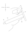
- FIG. 1 is a side view showing an outline of a peripheral structure of an instrument panel of a vehicle to which a column cover according to an embodiment of the present invention is applied.
- FIG. 2 is a perspective view of the column cover seen from the rear side of the vehicle.
- FIG. 3 is a perspective view of the column cover seen from the front of the vehicle.
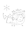
- FIG. 4 is a bottom perspective view of the upper cover on which the in-vehicle device is mounted.
- FIG. 5A is a schematic diagram showing the shape of the rib on the vehicle-mounted device side
- FIG. 5B is a schematic diagram showing the direction in which the vehicle-mounted device falls off.
- 6A to 6C are a top perspective view, a bottom perspective view, and a side view showing the in-vehicle device.
- 7A and 7B are a top perspective view and a bottom view of the upper cover showing the mounting portion.
- FIG. 1 is a side view showing an outline of the peripheral structure of a vehicle instrument panel to which a column cover according to this embodiment is applied.
- an instrument panel 10 at the front of the vehicle interior is provided with a meter unit 12 in front of the driver's seat.
- a steering column 14 is provided below the meter unit 12, penetrating in the front-rear direction of the vehicle and extending rearward of the vehicle.
- a steering shaft 16 is provided inside the steering column 14.
- a steering wheel 18 is attached to the rear end of the steering shaft 16, which is the end inside the vehicle cabin.
- the steering wheel 18 is connected to the front wheels via the steering shaft 16, a universal joint (not shown), a connecting shaft, a steering gear, a tie rod, and a knuckle arm. Therefore, the front wheels are steered by turning the steering wheel 18.
- the steering column 14 extends in the front-rear direction from the front of the instrument panel 10 to the rear of the instrument panel 10 within the vehicle interior, and surrounds the steering shaft 16 .
- the steering column 14 and the steering shaft 16 are configured so that their rear ends are displaced forward when an impact load acts on the steering wheel 18 side due to the driver leaning forward during a head-on collision of the vehicle.
- the steering column 14 has a front cylindrical portion that is fixed to a deck cross pipe (not shown) in the left-right direction that supports the instrument panel 10, and a rear cylindrical portion that is fixed to the front cylindrical portion via a resin mounting bracket (not shown) and into which the front cylindrical portion is inserted.
- the mounting bracket breaks due to an impact load input from the steering wheel 18, the rear cylindrical portion of the steering column 14 moves forward relative to the front cylindrical portion.
- the steering column 14 contracts in the extension direction, thereby efficiently absorbing the collision energy and reducing the impact of the secondary collision on the driver, while also creating space between the steering wheel 18 and the driver for deploying an airbag.
- the rear portion of the steering column 14 that protrudes from the instrument panel 10 into the passenger compartment is covered with a column cover 30 .
- the column cover 30 is disposed with the tip side of the column cover 30 inserted into an insertion opening 20 formed in the instrument panel 10, and covers the rear end side, which is a part of the steering column 14, along its axial direction.
- the traveling direction of the vehicle is referred to as "front”, and the rear of the vehicle is referred to as "rear”.
- the left side of the traveling direction of the vehicle is referred to as “left”, and the right side of the traveling direction of the vehicle is referred to as "right”.
- the left-right direction and the vehicle width direction are synonymous, and the front-rear direction and the vehicle direction are synonymous.
- the term “front end” refers to the front side of the vehicle.
- the term “rear end” refers to the rear side of the vehicle, and refers to the direction toward the side where the steering wheel 18 is attached relative to the steering column 14. The same definitions are used below.
- Figure 2 is a perspective view of the column cover from the rear side of the vehicle
- Figure 3 is a perspective view of the column cover from the front of the vehicle.
- the column cover 30 is a molded product made of resin, and includes an upper cover 31 and a lower cover 32.
- the upper cover 31 and the lower cover 32 each have a half shape obtained by dividing a bottomed box body having a generally rectangular cross section into upper and lower halves.
- An in-vehicle device 40 (described later) is provided on the upper surface side of the upper cover 31 .
- the upper cover 31 has a rear end side wall portion 31 a, a left side wall portion 31 b, a right side wall portion 31 c, and an upper wall portion 31 d.
- the upper cover 31 is open at its tip side and at its lower side in the vertical direction, and covers the steering column 14 from above in the vertical direction.
- a substantially semicircular rear cutout 34, through which the steering column 14 is inserted, is formed at the lower edge of the rear end side wall 31a of the upper cover 31.
- Substantially semicircular lateral cutouts 35L, 35R, through which an operating lever or the like is inserted, are formed at the lower edges of the left and right side wall portions 31b, 31c of the upper cover 31. This configuration can be seen in Figures 2 to 5.
- the upper wall portion 31d of the upper cover 31 is formed by arranging a first upper wall portion 31d1 and a second upper wall portion 31d2 in the front-rear direction in that order from the rear side.
- the first upper wall portion 31d1 is formed at a higher position than the second upper wall portion 31d2 via a step portion in the up-down direction.
- the upper wall portion 31d of the upper cover 31 is curved in an arc shape along the upper portion of the steering column 14 when viewed from the driver's side.
- the in-vehicle device 40 is attached via an attachment portion 50 provided on the rear end side of the upper cover 31, on the first upper wall portion 31d1, at the center in the left-right direction.
- the lower cover 32 has a rear end side wall portion 32a, a left side wall portion 32b, a right side wall portion 32c, and a bottom wall portion 32d.
- the lower cover 32 is open at its tip and at its upper side in the vertical direction, and faces the upper cover 31 to cover the steering column 14 from below in the vertical direction.
- a substantially semicircular rear cutout 37, through which the steering column 14 is inserted, is formed in the upper edge of the rear side wall 32a of the lower cover 32.
- Substantially semicircular lateral cutouts 38L, 38R, through which an operating lever or the like is inserted, are formed in the upper edges of the left and right side wall portions 32b, 32c of the lower cover 32.
- the lower wall portion 32d of the lower cover 32 is curved in an arc shape along the lower portion of the steering column 14 when viewed from the driver's side.
- a plurality of mating claws are arranged on the lower edges of the left and right side wall portions 31b, 31c of the upper cover 31. Meanwhile, mating portions (not shown) that fit with the mating claws are provided on the upper edges of the left and right side wall portions 32b, 32c of the lower cover 32.
- the box-shaped column cover 30 is formed by butting and combining the lower edges of the side wall portions 31b, 31c of the upper cover 31 with the upper edges of the side wall portions 32b, 32c of the lower cover 32. This allows the upper cover 31 to be easily joined to and detached from the lower cover 32 .
- Fig. 4 is a bottom perspective view of the upper cover on which the vehicle-mounted device is mounted
- Fig. 5(A) is a schematic diagram showing the shape of the ribs on the vehicle-mounted device side
- Fig. 5(B) is a schematic diagram showing the direction in which the vehicle-mounted device falls off
- Figs. 6(A) to 6(C) are top perspective views, bottom perspective views, and side views of the vehicle-mounted device
- Figs. 7(A) and 7(B) are top perspective views and bottom views of the upper cover showing the mounting portion.
- the in-vehicle device 40 has a storage section 41, a bottom plate section 42, and a fastening member 43.
- an in-vehicle camera that captures images of the interior of the vehicle is mounted in the space formed by the storage section 41 and the bottom plate section 42 as the in-vehicle device 40.
- a harness 48 that is connected to a control section and a power source in the vehicle is connected to the in-vehicle camera.
- the harness 48 is taken out from the rear side of the bottom plate section 42. Note that the equipment mounted in the storage section 41 as the in-vehicle device 40 is not limited to the in-vehicle camera.
- the in-vehicle device 40 is located between the column cover 30 and the meter unit 12 in a vertical position in a side view.
- the in-vehicle device 40 is located between the steering wheel 18 and the meter unit 12 in a side view.
- the in-vehicle device 40 does not protrude above the steering wheel 18, and can be installed without affecting the visibility of the meter unit 12.
- the rear end side of the in-vehicle device 40 is located so as to be visible from the driver's side through an opening (not shown) formed between spokes formed on the upper part of the steering wheel 18. This configuration can be seen in FIG. 1.
- the storage section 41 has a rear surface 41a, a left side surface 41b, a right side surface 41c, and a top surface 41d, so that the storage section 41 is formed in a box shape that is open downward, and stores the vehicle-mounted camera therein.
- the lower edge of the frame-shaped accommodation portion 41 is provided with a protrusion 47 for positioning the accommodation portion 41 relative to the mounting portion 50, a rib 46, and a locking piece 45.
- the rear surface 41a of the storage section 41 is a flat surface extending upward from the upper edge of the rear end wall section 31a of the upper cover 31 along the rear end wall section 31a.
- the left-right direction of the rear surface 41a of the storage section 41 is curved in an arc shape along the upper edge of the rear end wall section 31a of the upper cover 31. This configuration can be seen in Figures 2 and 6(A).
- At least the rear surface 41a of the storage section 41 is formed of a light-transmitting material.
- the upper surface 41d of the storage section 41 has a first upper surface 41d1 that is smoothly inclined or curved downward from the upper end of the rear surface 41a of the storage section 41, which is also the rear end, toward the front, and a second upper surface 41d2 that has a steeper downward slope from the rear end of the first upper surface 41d1.
- This configuration can be seen in Figures 3 and 6(C).
- the upper edges of the left side surface 41b and the right side surface 41c of the storage portion 41 are connected at their upper ends to both left and right ends of a top surface 41d of the storage portion 41, respectively.
- the protrusion 47 is an arc-shaped protrusion formed by protruding the lower end side of the rear surface 41a of the storage section 41 downward from the bottom plate section 42. This configuration can be seen in Figures 5(A), 5(B) and 6(C).
- the ribs 46 are provided in pairs at the front and rear of the lower edge of the frame-shaped storage section 41 on the lower end sides of the left side surface section 41b and the right side surface section 41c of the storage section 41. Note that since the left side surface section 41b and the right side surface section 41c are inclined inwardly to the left and right as they extend forward, the ribs 46, 46 arranged side by side in the front and rear direction are also offset in the left and right direction.
- Each rib 46 is a plate-like member protruding downward from the lower end side of the left side surface portion 41b and the right side surface portion 41c of the storage portion 41, and has a guide portion 46a that slopes upward toward the rear. In other words, the guide portion 46a slopes downward from the rear end of the rib 46 toward the front. This configuration can be seen in Figures 4 and 6.
- the locking piece 45 is provided on the lower edge of the frame-shaped storage section 41, at the center of the left and right sides of the rear end of the upper surface 41d of the storage section 41.
- the locking piece 45 is a plate-like member bent into an L-shape and extends downward from the underside of the rear end of the upper surface 41d of the storage section 41. See FIG. 6(B) for this configuration.
- the bottom plate portion 42 is a plate-like member that closes the lower side of the open storage portion 41.
- the upper side of the bottom plate portion 42 supports the vehicle-mounted camera stored in the storage portion 41.
- the lower side of the bottom plate portion 42 abuts against the first upper wall portion 31d1 (mounting portion 50) of the upper cover 31.
- the fastening member 43 is a member that fastens the in-vehicle device 40 to the upper cover 31.
- one fastening member 43 is disposed in the center in the left-right direction on the front end side of the bottom plate portion 42, and a pair of fastening members 43 are disposed on the left and right sides on the rear end side of the bottom plate portion 42.
- the fastening member 43 includes a shaft portion 43a that protrudes downward from the lower surface of the bottom plate portion 42, and a head portion 43b that is provided on the lower end side of the shaft portion 43a and has a disk shape with a diameter larger than that of the shaft portion 43a.
- the bottom plate portion 42 is provided with a front fixing hole 42a and rear fixing holes 42b, 42b to which the fastening member 43 is fixed. This configuration may be seen in Figures 4 and 6(B).
- the harness 48 which is connected to the in-vehicle device 40 and extends toward the upper cover 31, has an excess length.
- the excess length of the harness 48 is set to be at least longer than the amount of movement of the column cover 30 when the steering column 14 contracts. In other words, the length of the harness 48 connected to the in-vehicle device 40 has an excess length in case the in-vehicle device 40 falls off.
- the mounting portion 50 on the upper cover 31 side has an abutment surface 51, a first locking hole 52, a second locking hole 53, 53, a third locking hole 54, guide holes 55, 55, 55, 55, a harness insertion portion 56, and a recess 57.
- the mounting portion 50 is an attachment area where the vehicle-mounted device 40 is attached, and is formed on the first upper wall portion 31d1 of the upper cover 31.
- the mounting portion 50 also has a detachment mechanism 60 that allows the vehicle-mounted device 40 to be detached from the upper cover 31 side.
- the contact surface 51 is a flat surface formed in a rectangular shape in a plan view, and contacts the entire bottom plate portion 42 of the in-vehicle device 40.
- the contact surface 51 is formed by recessing the upper surface side of the first upper wall portion 31d1 of the upper cover 31, which is curved in an arc shape.
- the first locking hole 52 is a locking portion that locks the in-vehicle device 40 to the mounting portion 50, and is a hole provided on the abutment surface 51 so that the fastening member 43 can be inserted.
- the first locking hole 52 is located toward the rear of the left-right center of the abutment surface 51.
- the first locking hole 52 is sized to allow the shaft portion 43a of the fastening member 43 to be inserted therethrough, but is set to a size that does not allow the head portion 43b of the fastening member 43 to be inserted therethrough.
- the second locking holes 53, 53 are locking portions that lock the in-vehicle device 40 to the mounting portion 50 side, and are holes provided on the abutment surface 51 so that the fastening member 43 can be inserted.
- the second locking holes 53, 53 are arranged in pairs on both the left and right sides of the rear end of the abutment surface 51.
- the second locking holes 53 are sized to allow the shaft portion 43a of the fastening member 43 to be inserted, but are set to a size that does not allow the head portion 43b of the fastening member 43 to be inserted.
- the second locking holes 53 are formed in an elongated hole shape facing rearward by the second displacement allowing portion 62 described below.
- the third locking hole 54 is a hole on the abutment surface 51 to which the locking piece 45 of the vehicle-mounted device 40 is locked.
- the third locking hole 54 is located in front of the first locking hole 52, on the front end side of the center in the left-right direction of the abutment surface 51, and is a vertical through hole formed in an L-shape in a plan view.
- the guide holes 55 are holes on the contact surface 51 through which the ribs 46 of the in-vehicle device 40 are inserted.
- the guide holes 55 are rectangular holes that are long in the front-rear direction and are located on both the left and right ends of the contact surface 51, and a pair of guide holes 55 are provided on the front and rear sides. Please refer to Figure 5 (A) for the state in which the ribs 46 are inserted into the guide holes 55.
- the harness insertion portion 56 is a hole on the contact surface 51 through which the harness 48 connected to the in-vehicle device 40 is inserted.
- the harness insertion portion 56 is located on the front end side of the contact surface 51, is connected to one side of the third locking hole 54 in the left-right direction, and is formed with a large opening toward the rear of the third locking hole 54. This configuration can be seen in Figures 7(A) and 7(B).
- the recess 57 is a recess into which the protrusion 47 of the in-vehicle device 40 fits.
- the recess 57 is formed by cutting out the rear end side of the abutment surface 51 in an arc shape along the rear end of the upper cover 31.
- the recess 57 is also formed by cutting out the rear end of the abutment surface 51 downward toward the front so that the rear is open.
- the left-right center of the rear end of the abutment surface 51 is flush with the left-right center of the rear end of the upper cover 31.
- a pair of recesses 57 are arranged on the outside left and right sides of the rear end of the abutment surface 51. This configuration can be seen in Figures 5(A), 5(B) and 7(A).
- the attachment portion 50 has a detachment mechanism 60 that includes a first displacement-permitting portion 61 arranged in line behind the first locking hole 52, and a second displacement-permitting portion 62 arranged adjacent to the rear of the second locking hole 53.
- the first displacement allowance portions 61 are holes arranged behind the first locking holes 52 and are connected via connection portions 63.
- the first displacement allowance portions 61 have a larger diameter than the first locking holes 52 and are formed to a size that allows the heads 43b of the fastening members 43 to be inserted therethrough with ease. In other words, the fastening members 43 inserted through the first displacement allowance portions 61 can easily slip out from above the upper cover 31.
- the connecting portion 63 is formed so that its width in the left-right direction is the same as or slightly smaller than that of the shaft portion 43a of the fastening member 43, and can be elastically pushed apart. That is, the first locking hole 52, the connection portion 63, and the first displacement allowing portion 61 are formed in a gourd shape in a plan view. Also, the shaft portion 43a of the fastening member 43 inserted into the first locking hole 52 can slide to the first displacement allowing portion 61 via the connection portion 63.
- the second displacement allowance portion 62 is a hole that is connected to the rear end side of the second locking hole 53, which is a long hole in the front-rear direction, and is a portion that is formed wider in the left-right direction than the second locking hole 53.
- the second displacement allowance portion 62 is formed to be larger in diameter than the head 43b of the fastening member 43. In other words, the fastening member 43 inserted into the second displacement allowance portion 62 can be removed from above the upper cover 31.
- the vehicle-mounted device 40 placed on the abutment surface 51 of the upper cover 31 is attached to the upper cover 31 side by fixing the fastening member 43 inserted into the first engagement hole 52 of the upper cover 31 to the front fixing hole 42a of the bottom plate portion 42, and fixing the fastening members 43, 43 inserted into the second engagement holes 53, 53 of the upper cover 31 to the rear fixing holes 42b, 42b of the bottom plate portion 42.
- the ribs 46 provided on both the left and right ends of the lower end of the vehicle-mounted device 40 are inserted into the guide holes 55 on the contact surface 51 side, and the locking piece 45 provided on the front end side of the lower end of the vehicle-mounted device 40 is inserted into the third locking hole 54, so that the vehicle-mounted device 40 can be positioned at a predetermined position on the contact surface 51.
- the in-vehicle device 40 can be positioned at a predetermined position on the abutment surface 51 while allowing the in-vehicle device 40 to slide rearward. This makes it easier to attach the in-vehicle device 40 to the upper cover 31 .
- the vehicle-mounted device 40 attached to the top surface of the upper cover 31 is only permitted to move rearward and upward due to the protrusion 47 of the vehicle-mounted device 40. Therefore, when a rearward or downward external force F acts on the upper surface 41d of the storage section 41, the vehicle-mounted device 40 smoothly falls off from the upper cover 31 side. This configuration can be seen in Figures 5(A) and 5(B).
- the column cover 30 moves forward (the column cover 30 displaces forward along with the displacement of the rear end of the steering column 14), and if the in-vehicle device 40 on the column cover 30 comes into contact with the meter unit 12 or the like on the instrument panel 10 side, the in-vehicle device 40 falls off smoothly from the column cover 30. This prevents the in-vehicle device 40 from impeding the contraction of the steering column 14.
- the harness 48 connected to the vehicle-mounted device 40 has a surplus length greater than the amount of movement of the column cover 30 that accompanies the contraction of the steering column 14, so that when the vehicle-mounted device 40 falls off the column cover 30, the harness 48 does not prevent the vehicle-mounted device 40 from falling off.
- the present invention is not limited to the above-described embodiment, and can be modified or improved as appropriate.
- a column cover that is attached to a steering column so as to cover the steering column protruding rearward from an instrument panel
- the column cover includes a lower cover constituting a lower portion of the column cover, an upper cover attached to the lower cover constituting an upper portion of the column cover, and an in-vehicle device attached to an attachment area on an upper surface of the upper cover,
- the in-vehicle device can fall off the upper cover.
- the on-board device when the steering wheel receives an impact load of a predetermined magnitude or more due to a vehicle collision or the like, causing the steering column to displace forward, the on-board device can be prevented from getting caught on the instrument panel, thereby preventing the forward movement of the steering column from being hindered.
- the in-vehicle device has a fastening member that fastens the in-vehicle device to the mounting area
- the mounting region includes a first fastening hole to which the fastening member is fastened, and a second fastening hole formed rearward of the first fastening hole, continuous with the first fastening hole, and having a larger diameter than the first fastening hole,
- the in-vehicle device even if the in-vehicle device gets caught on the instrument panel when the steering column moves forward, the in-vehicle device will not move backward relative to the upper cover and fall off, thereby preventing the forward movement of the upper cover from being hindered, and the forward movement of the steering column will be smooth.
- the in-vehicle device has a rib that is inserted into a positioning hole in the front-rear direction formed in the mounting area, The rib slopes upward toward the rear.
- a column cover according to any one of (1) to (3). According to this configuration, the vehicle-mounted device can be easily positioned at the mounting position. Also, when the front end of the vehicle-mounted device comes into contact with the instrument panel, the inclination of the rib causes the vehicle-mounted device to fly upward and rearward from the upper cover. This allows the vehicle-mounted device to be more smoothly removed from the upper cover.
- the mounting region is formed with a recess into which the in-vehicle device is fitted,
- the recess is open at the rear side.
- a column cover according to any one of (1) to (4). According to this configuration, the in-vehicle device can slide in the front-rear direction relative to the upper portion of the column cover, so that the in-vehicle device can be more reliably removed.
Landscapes
- Engineering & Computer Science (AREA)
- Chemical & Material Sciences (AREA)
- Combustion & Propulsion (AREA)
- Transportation (AREA)
- Mechanical Engineering (AREA)
- Steering Controls (AREA)
Abstract
インストルメントパネルより後方に突出するステアリングコラムを覆うようにステアリングコラムに取り付けられるコラムカバーにおいて、コラムカバーは、コラムカバーの下部を構成する下部カバーと、下部カバーに取り付けられてコラムカバーの上部を構成する上部カバーと、上部カバー上面の取付領域に取り付けられる車載装置とを有し、車載装置は、ステアリングコラムの前方への変位と共にコラムカバーが前方に変位して車載装置がインストルメントパネルに接触した場合、上部カバーから脱落可能である。
Description
本発明は、ステアリングコラムの後部を覆うコラムカバーに関する。
車両が一次衝突した場合、慣性力によって運転者が前方のステアリングハンドルに二次衝突する。このため、車両が一次衝突した際にステアリングコラムを収縮させて衝突のエネルギーを吸収し、二次衝突における運転者への作用荷重を低減するとともに、エアバックが展開するスペースを確保する構成が一般的に知られている。
特許文献1では、アッパ部品及びロア部品から構成され、ステアリングコラムの後端を覆うコラムカバーについて、アッパ部品をステアリングコラム及びロア部品から容易に脱落可能にしたコラムカバーが開示されている。
上記特許文献1に記載のコラムカバーは、ステアリングコラムの収縮によるエネルギー吸収性能は保持しつつ、外観を良好に保つことを意図したものである。しかし、近年では、車室内に様々な車載装置が搭載されるようになり、特にコラムカバーの上部に設けた車載装置によってステアリングコラムの収縮が阻害される場合があり得るという課題がある。
本発明は、このような状況に鑑みてなされたものであり、コラムカバーの上に設けた車載装置がインストルメントパネル側に引っ掛かることによって、ステアリングコラムの収縮に伴うステアリングコラム後端の前方への変位が阻害されること、を防止するコラムカバーを提供することを目的とする。
本発明の上記目的は、下記の構成により達成される。
[1] インストルメントパネルより後方に突出するステアリングコラムを覆うように前記ステアリングコラムに取り付けられるコラムカバーにおいて、
前記コラムカバーは、前記コラムカバーの下部を構成する下部カバーと、前記下部カバーに取り付けられて前記コラムカバーの上部を構成する上部カバーと、前記上部カバー上面の取付領域に取り付けられる車載装置とを有し、
前記車載装置は、前記ステアリングコラムの前方への変位と共に前記コラムカバーが前方に変位して前記車載装置が前記インストルメントパネルに接触した場合、前記上部カバーから脱落可能である、
コラムカバー。
[2] 前記上部カバーは、前記ステアリングコラムの前方への変位と共に前記コラムカバーが前方に変位して前記上部カバーが前記インストルメントパネルに接触した場合、前記下部カバーから脱落可能である、
[1]に記載のコラムカバー。
[3] 前記車載装置は、前記車載装置を前記取付領域に締結する締結部材を有し、
前記取付領域は、前記締結部材が締結される第1締結孔と、前記第1締結孔の後方に前記第1締結孔と連続的に形成されるとともに前記第1締結孔よりも径が大きい第2締結孔とを有し、
前記ステアリングコラムの前方への変位と共に前記コラムカバーが前方に変位して前記車載装置が前記インストルメントパネルに接触した場合、前記締結部材は、前記車載装置の前方への移動と共に前記第1締結孔との締結が解除されて前記第2締結孔内に収容される、
[1]又は[2]に記載のコラムカバー。
[4] 前記車載装置は、前記取付領域に形成された前後方向の位置決め孔に差し込まれるリブを有し、
前記リブは、後方に向かうにつれて上側に傾斜する、
[1]~[3]の何れか1つに記載のコラムカバー。
[5] 前記取付領域には、前記車載装置が嵌合される凹部が形成され、
前記凹部は、後方側が開放されている、
[1]~[4]の何れか1つに記載のコラムカバー。
[1] インストルメントパネルより後方に突出するステアリングコラムを覆うように前記ステアリングコラムに取り付けられるコラムカバーにおいて、
前記コラムカバーは、前記コラムカバーの下部を構成する下部カバーと、前記下部カバーに取り付けられて前記コラムカバーの上部を構成する上部カバーと、前記上部カバー上面の取付領域に取り付けられる車載装置とを有し、
前記車載装置は、前記ステアリングコラムの前方への変位と共に前記コラムカバーが前方に変位して前記車載装置が前記インストルメントパネルに接触した場合、前記上部カバーから脱落可能である、
コラムカバー。
[2] 前記上部カバーは、前記ステアリングコラムの前方への変位と共に前記コラムカバーが前方に変位して前記上部カバーが前記インストルメントパネルに接触した場合、前記下部カバーから脱落可能である、
[1]に記載のコラムカバー。
[3] 前記車載装置は、前記車載装置を前記取付領域に締結する締結部材を有し、
前記取付領域は、前記締結部材が締結される第1締結孔と、前記第1締結孔の後方に前記第1締結孔と連続的に形成されるとともに前記第1締結孔よりも径が大きい第2締結孔とを有し、
前記ステアリングコラムの前方への変位と共に前記コラムカバーが前方に変位して前記車載装置が前記インストルメントパネルに接触した場合、前記締結部材は、前記車載装置の前方への移動と共に前記第1締結孔との締結が解除されて前記第2締結孔内に収容される、
[1]又は[2]に記載のコラムカバー。
[4] 前記車載装置は、前記取付領域に形成された前後方向の位置決め孔に差し込まれるリブを有し、
前記リブは、後方に向かうにつれて上側に傾斜する、
[1]~[3]の何れか1つに記載のコラムカバー。
[5] 前記取付領域には、前記車載装置が嵌合される凹部が形成され、
前記凹部は、後方側が開放されている、
[1]~[4]の何れか1つに記載のコラムカバー。
本発明によれば、車両の衝突等によってステアリングハンドルから前方に向けて受けた所定以上の衝撃荷重によって、前記ステアリングコラムを収縮させる場合に、前記車載装置が前記インストルメントパネル側に引っ掛かることによって、前記ステアリングコラム後端の前方への変位が阻害されることを防止できる。
以下、本発明の一実施形態に係るコラムカバーについて、図面を参照して説明する。また、本実施形態は本発明の一例を示したものであって、本発明は本実施形態に限定されるものではない。また、本実施形態には種々の変更又は改良を加えることが可能であり、その様な変更又は改良を加えた形態も本発明に含まれ得る。
(全体構成)
図1は、本実施形態に係るコラムカバーを適用した車両のインストルメントパネルの周辺構造の概略を示す側面図である。図1に示すように、車室内の前部のインストルメントパネル10には、運転席の前方において、メータユニット12が設けられている。メータユニット12の下方には、車両前後方向に貫通して車両の後方に延びるステアリングコラム14が設けられている。ステアリングコラム14の内部には、ステアリングシャフト16が設けられている。
図1は、本実施形態に係るコラムカバーを適用した車両のインストルメントパネルの周辺構造の概略を示す側面図である。図1に示すように、車室内の前部のインストルメントパネル10には、運転席の前方において、メータユニット12が設けられている。メータユニット12の下方には、車両前後方向に貫通して車両の後方に延びるステアリングコラム14が設けられている。ステアリングコラム14の内部には、ステアリングシャフト16が設けられている。
ステアリングシャフト16の車室内側の端部である後端部には、ステアリングハンドル18が取付られている。ステアリングハンドル18は、ステアリングシャフト16と、不図示のユニバーサルジョイントと、連結シャフトと、ステアリングギヤと、タイロッドと、ナックルアームと、を介して前輪と接続されている。このため、ステアリングハンドル18の操向操作によって前輪が操舵される。
ステアリングコラム14は、インストルメントパネル10の前方から、車室内であるインストルメントパネル10の後方まで前後方向に延在し、ステアリングシャフト16を囲繞している。
ステアリングコラム14及びステアリングシャフト16は、車両が正面衝突した際に運転者が前のめりになることでステアリングハンドル18側から衝撃荷重が作用した場合、その後端側が前方に変位するように構成されている。
ステアリングコラム14及びステアリングシャフト16は、車両が正面衝突した際に運転者が前のめりになることでステアリングハンドル18側から衝撃荷重が作用した場合、その後端側が前方に変位するように構成されている。
ステアリングコラム14の具体的な構成の一例について説明する。ステアリングコラム14は、インストルメントパネル10を支持する左右方向の不図示のデッキクロスパイプに固定される前側筒部と、不図示の樹脂製の取付ブラケットを介して前側筒部側に固定され、前側筒部が内挿される後側筒部と、を有する。ステアリングコラム14は、ステアリングハンドル18から入力された衝撃荷重によって取付ブラケットが破断すると、後側筒部が前側筒部に対して前進する。
すなわち、ステアリングコラム14は、車両が一次衝突した場合、延在方向に収縮することによって、衝突エネルギーを効率的に吸収して運転者への二次衝突の衝撃を低減するとともに、ステアリングハンドル18と運転者との間に、エアバックを展開するスペースを形成できる。
すなわち、ステアリングコラム14は、車両が一次衝突した場合、延在方向に収縮することによって、衝突エネルギーを効率的に吸収して運転者への二次衝突の衝撃を低減するとともに、ステアリングハンドル18と運転者との間に、エアバックを展開するスペースを形成できる。
ステアリングコラム14におけるインストルメントパネル10から車室内側に突出する後側の部分は、コラムカバー30で覆われている。
コラムカバー30は、インストルメントパネル10に形成された挿通用開口部20にコラムカバー30の先端側が挿通された状態で配置されていて、ステアリングコラム14の一部である後端側をその軸方向に沿って覆っている。
コラムカバー30は、インストルメントパネル10に形成された挿通用開口部20にコラムカバー30の先端側が挿通された状態で配置されていて、ステアリングコラム14の一部である後端側をその軸方向に沿って覆っている。
ここで、本実施例において、車両の進行方向を「前」、車両の後進後方を「後」と称する。車両の進行方向左側を「左」、車両の進行方向右側を「右」と称する。また、左右方向と、車幅方向とは同義であり、前後方向と、車両方向とは同義である。
また、「先端側」とは車両前方側を意味する。また、「後端側」とは車両後方側を意味するものとし、ステアリングコラム14を基準とするステアリングハンドル18が取付けられる側の方向を意味するものとする。以下、同様に定義する。
また、「先端側」とは車両前方側を意味する。また、「後端側」とは車両後方側を意味するものとし、ステアリングコラム14を基準とするステアリングハンドル18が取付けられる側の方向を意味するものとする。以下、同様に定義する。
次に、図1~図3に基づき、コラムカバーの具体的な構成について説明する。図2は、車両後方側からのコラムカバーの斜視図であり、図3は、車両前方からのコラムカバーの斜視図である。
コラムカバー30は、樹脂による成形品であり、上部カバー31と、下部カバー32と、を有する。上部カバー31及び下部カバー32は、それぞれが断面略矩形状の有底箱体を上下に2分割した半割形状を有する。
上部カバー31の上面側には、後述する車載装置40が設けられている。
上部カバー31の上面側には、後述する車載装置40が設けられている。
上部カバー31は、後端側壁部31aと、左側壁部31bと、右側壁部31cと、上壁部31dと、を有する。上部カバー31は、先端側及び鉛直方向下側が開放され、ステアリングコラム14を鉛直方向に対して上側から覆っている。
上部カバー31の後端側壁部31aの下縁には、ステアリングコラム14を挿通させる略半円状の後側切欠部34が形成されている。上部カバー31の左右の側壁部31b、31cの下端縁には、操作レバー等を挿通させる略半円状の側方切欠部35L、35Rが形成されている。この構成は、図2~図5を参照するとよい。
上部カバー31の上壁部31dは、後側から順に、第1上壁部31d1と、第2上壁部31d2と、が前後方向に並べて形成される。第1上壁部31d1は、上下方向の段部を介して、第2上壁部31d2よりも高い位置に形成される。また、上部カバー31の上壁部31dは、運転者側から見て、ステアリングコラム14の上部に沿って円弧状に湾曲している。
車載装置40は、上部カバー31の後端側である第1上壁部31d1上の左右方向中央側に設けた取付部50を介して、取付けられている。
上部カバー31の後端側壁部31aの下縁には、ステアリングコラム14を挿通させる略半円状の後側切欠部34が形成されている。上部カバー31の左右の側壁部31b、31cの下端縁には、操作レバー等を挿通させる略半円状の側方切欠部35L、35Rが形成されている。この構成は、図2~図5を参照するとよい。
上部カバー31の上壁部31dは、後側から順に、第1上壁部31d1と、第2上壁部31d2と、が前後方向に並べて形成される。第1上壁部31d1は、上下方向の段部を介して、第2上壁部31d2よりも高い位置に形成される。また、上部カバー31の上壁部31dは、運転者側から見て、ステアリングコラム14の上部に沿って円弧状に湾曲している。
車載装置40は、上部カバー31の後端側である第1上壁部31d1上の左右方向中央側に設けた取付部50を介して、取付けられている。
下部カバー32は、後端側壁部32aと、左側壁部32b、右側壁部32cと、下壁部32dと、を有する。下部カバー32は、先端及び鉛直方向上側が開放され、上部カバー31に対向して、ステアリングコラム14を鉛直方向に対して下側から覆っている。
下部カバー32の後端側壁部32aの上端縁には、ステアリングコラム14を挿通させる略半円状の後側切欠部37が形成されている。下部カバー32の左右の側壁部32b、32cの上端縁には、操作レバー等を挿通させる略半円状の側方切欠部38L、38Rが形成されている。
下部カバー32の下壁部32dは、運転者側から見て、ステアリングコラム14の下部に沿って円弧状に湾曲している。
下部カバー32の後端側壁部32aの上端縁には、ステアリングコラム14を挿通させる略半円状の後側切欠部37が形成されている。下部カバー32の左右の側壁部32b、32cの上端縁には、操作レバー等を挿通させる略半円状の側方切欠部38L、38Rが形成されている。
下部カバー32の下壁部32dは、運転者側から見て、ステアリングコラム14の下部に沿って円弧状に湾曲している。
本実施例では、上部カバー31の左右の側壁部31b、31cの下端縁には、不図示の嵌合爪部が複数並べて設けられている。その一方で、下部カバー32の左右の側壁部32b、32cの上端縁には、嵌合爪部のそれぞれと嵌まり合う不図示の嵌合部が設けられている。これにより、上部カバー31の側壁部31b、31cの下端縁と、下部カバー32の側壁部32b、32cの上端縁と、を突き合わせて組み合わせることにより、箱状のコラムカバー30が形成される。
これにより、上部カバー31は、下部カバー32に対して、係脱容易に接合される。
これにより、上部カバー31は、下部カバー32に対して、係脱容易に接合される。
該構成によれば、ステアリングコラム14の後端が前方に変位し、上部カバー31の前端がインストルメントパネル10に形成された挿通用開口部20やメータユニット12に接触した場合、上部カバー31が、スムーズに下部カバー32から脱落する。
すなわち、ステアリングハンドル18からステアリングコラム14に衝撃荷重が作用した際に、コラムカバー30がインストルメントパネル10側に引っ掛かってステアリングコラム14の前進を阻害する事態を効率的に防止できる。
すなわち、ステアリングハンドル18からステアリングコラム14に衝撃荷重が作用した際に、コラムカバー30がインストルメントパネル10側に引っ掛かってステアリングコラム14の前進を阻害する事態を効率的に防止できる。
次に、図1~図7に基づき、車載装置と、上部カバー側の取付部の具体的な構成について説明する。図4は、車載装置が搭載された上部カバーの底面斜視図であり、図5(A)は、車載装置側のリブの形状を示した模式図であり、図5(B)は、車載装置の脱落方向を示した模式図であり、図6(A)~図6(C)は、車載装置を示した上面斜視図、底面斜視図、側面図であり、図7(A)及び図7(B)は、取付部を示した上部カバーの上面斜視図及び底面図である。
車載装置40は、収容部41と、底板部42と、締結部材43と、を有する。本実施例では、車載装置40として、収容部41と底板部42とで形成されるスペースに、車室内を撮影する車載カメラが搭載されている。また、車載カメラには、車室内の制御部や電源に接続されるハーネス48が接続されている。ハーネス48は、底板部42の後部側から取り出される。なお、車載装置40として収容部41に搭載される機器は車載カメラに限られない。
車載装置40の上下位置は、側面視でコラムカバー30と、メータユニット12と、の間に配置される。また、車載装置40の前後位置は、側面視でステアリングハンドル18と、メータユニット12と、の間に配置される。これにより、車載装置40は、ステアリングハンドル18の上方には突出しないため、メータユニット12の視認性には影響することなく設置できる。その一方で、車載装置40の後端側は、ステアリングハンドル18上部に形成されるスポークの間に形成される不図示の開口部を介して、運転者側から視認可能に配置される。この構成は、図1を参照するとよい。
車載装置40の上下位置は、側面視でコラムカバー30と、メータユニット12と、の間に配置される。また、車載装置40の前後位置は、側面視でステアリングハンドル18と、メータユニット12と、の間に配置される。これにより、車載装置40は、ステアリングハンドル18の上方には突出しないため、メータユニット12の視認性には影響することなく設置できる。その一方で、車載装置40の後端側は、ステアリングハンドル18上部に形成されるスポークの間に形成される不図示の開口部を介して、運転者側から視認可能に配置される。この構成は、図1を参照するとよい。
収容部41は、後面部41aと、左側面部41bと、右側面部41cと、上面部41dと、を有する。これにより、収容部41は、下方が開放された箱状に形成され、車載カメラが収容される。
また、枠状に形成された収容部41の下端縁には、取付部50に位置決めするための突出部47と、リブ46と、係止片45と、が設けられる。
また、枠状に形成された収容部41の下端縁には、取付部50に位置決めするための突出部47と、リブ46と、係止片45と、が設けられる。
収容部41の後面部41aは、上部カバー31の後端側壁部31aの上縁から上側で、後端側壁部31aに沿って延在するフラットな面である。また、収容部41の後面部41aの左右方向は、上部カバー31の後端側壁部31aの上縁に沿って円弧状に湾曲している。この構成は、図2及び図6(A)を参照するとよい。なお、収容部41のうち、少なくとも後面部41aは、透光性のある部材によって形成される。
収容部41の上面部41dは、後端でもある収容部41の後面部41aの上端から前方に向かうにつれて滑らかに下方に傾斜又は湾曲する第1上面部41d1と、第1上面部41d1の後端から下方傾斜を急にした第2上面部41d2と、を有する。この構成は、図3及び図6(C)を参照するとよい。
収容部41の左側面部41b及び右側面部41cの上縁は、その上端側が収容部41の上面部41dの左右両端側とそれぞれ連接されている。
収容部41の上面部41dは、後端でもある収容部41の後面部41aの上端から前方に向かうにつれて滑らかに下方に傾斜又は湾曲する第1上面部41d1と、第1上面部41d1の後端から下方傾斜を急にした第2上面部41d2と、を有する。この構成は、図3及び図6(C)を参照するとよい。
収容部41の左側面部41b及び右側面部41cの上縁は、その上端側が収容部41の上面部41dの左右両端側とそれぞれ連接されている。
突出部47は、収容部41の後面部41aの下端側を、底板部42よりも下方に突出することによって形成された円弧状の突出片である。この構成は、図5(A)、図5(B)及び図6(C)を参照するとよい。
リブ46は、枠状に形成される収容部41の下端縁のうち、収容部41の左側面部41b及び右側面部41cの下端側に前後一対それぞれ設けられている。なお、左側面部41bと、右側面部41cと、は前方に向けて左右内側に傾斜しているため、前後に並べて配置されたリブ46、46も、左右方向にもオフセットされている。
各リブ46は、収容部41の左側面部41b及び右側面部41cの下端側から下方に突出された板状部材であって、後方に向かうにつれて上側に傾斜するガイド部46aを有する。言い換えると、ガイド部46aは、リブ46の後端から前方に向かって下方傾斜している。この構成は、図4及び図6を参照するとよい。
各リブ46は、収容部41の左側面部41b及び右側面部41cの下端側から下方に突出された板状部材であって、後方に向かうにつれて上側に傾斜するガイド部46aを有する。言い換えると、ガイド部46aは、リブ46の後端から前方に向かって下方傾斜している。この構成は、図4及び図6を参照するとよい。
係止片45は、枠状に形成される収容部41の下端縁のうち、収容部41の上面部41dの後端側の左右中央側に設けられている。係止片45は、L字状に屈曲形成された板状部材であって、収容部41の上面部41dの後端の下面側から下方に向けて延在する。この構成は、図6(B)を参照するとよい。
底板部42は、開放形成された収容部41の下面側を閉じる板状部材である。底板部42の上面側では、収容部41に収容された車載カメラを支持している。底板部42の下面側は、上部カバー31の第1上壁部31d1(取付部50)と当接する。
締結部材43は、車載装置40を上部カバー31側に締結する部材である。図示する例では、締結部材43は、底板部42の前端側の左右方向中央に1つ配置され、底板部42の後端側に左右一対配置されている。
本実施例では、締結部材43は、底板部42の下面から下方に突出する軸部43aと、軸部43aの下端側に設けられて軸部43aより径の大きい円板状に形成された頭部43bと、を備える。底板部42には、締結部材43が固定される前固定孔42aと、後固定孔42b、42bと、が設けられている。この構成は、図4及び図6(B)を参照するとよい。
本実施例では、締結部材43は、底板部42の下面から下方に突出する軸部43aと、軸部43aの下端側に設けられて軸部43aより径の大きい円板状に形成された頭部43bと、を備える。底板部42には、締結部材43が固定される前固定孔42aと、後固定孔42b、42bと、が設けられている。この構成は、図4及び図6(B)を参照するとよい。
車載装置40に接続され、上部カバー31側に延びるハーネス48に余長を設けた。ハーネス48は、余長として、少なくともステアリングコラム14が収縮した際のコラムカバー30の移動量よりも長くなるように設定する。言い換えると、車載装置40に接続されるハーネス48の長さに、車載装置40の脱落に備えた余長を持たせている。
上部カバー31側の取付部50は、当接面51と、第1係止孔52と、第2係止孔53、53と、第3係止孔54と、ガイド孔55、55、55、55と、ハーネス挿通部56と、凹部57と、を有する。取付部50は、車載装置40が取付けられる取付領域であり、上部カバー31の第1上壁部31d1に形成される。また、取付部50は、車載装置40を上部カバー31側から脱落可能にする脱落機構60を有する。
当接面51は、平面視で長方形状に形成されたフラットな面であり、車載装置40の底板部42の全体が当接する。当接面51は、円弧状に湾曲する上部カバー31の第1上壁部31d1の上面側を凹設するようにして形成される。
第1係止孔52は、車載装置40を取付部50側に係止する係止部であって、締結部材43が挿通されるように当接面51上に設けた孔である。第1係止孔52は、当接面51の左右方向中央の後部寄りに配置される。また、第1係止孔52は、締結部材43の軸部43aが挿通可能な大きさである一方で、締結部材43の頭部43bは、挿通できない大きさに設定される。
第2係止孔53、53は、車載装置40を取付部50側に係止する係止部であって、締結部材43が挿通されるように当接面51上に設けた孔である。第2係止孔53、53は、当接面51の後端の左右両側に一対配置される。また、第2係止孔53は、締結部材43の軸部43aが挿通可能な大きさである一方で、締結部材43の頭部43bは、挿通できない大きさに設定される。さらに、第2係止孔53は、後述の第2変位許容部62により、後方に向けた長孔状に形成されている。
第3係止孔54は、車載装置40の係止片45が係止される当接面51上の孔である。第3係止孔54は、第1係止孔52の前方であって、当接面51の左右方向中央の前端側に配置され、平面視でL字状に形成された上下方向の貫通孔である。
ガイド孔55は、車載装置40のリブ46が挿通される当接面51上の孔である。ガイド孔55は、当接面51の左右両端側に配置された前後方向に長い長方形状の孔であって、それぞれ前後一対設けられている。ガイド孔55にリブ46が挿通された状態については、図5(A)を参照するとよい。
ハーネス挿通部56は、車載装置40に接続されるハーネス48が挿通される当接面51上の孔である。ハーネス挿通部56は、当接面51の前端側であって、第3係止孔54の左右方向一方側と連接し、第3係止孔54よりも後方に向けて大きく開口形成されている。この構成は、図7(A)及び図7(B)を参照するとよい。
凹部57は、車載装置40の突出部47が嵌合する凹部である。凹部57は、当接面51の後端側を上部カバー31の後端に沿って円弧状に切り欠くことにより形成される。また、凹部57は、後方が開放されるように、当接面51の後端を、下方前側に向けて切欠くことにより形成される。なお、図示する例では、当接面51の後端の左右中央と、上部カバー31の後端の左右中央と、は面一になっている。このため、凹部57は、当接面51の後端の左右外側に一対配置されている。この構成は、図5(A)、図5(B)及び図7(A)を参照するとよい。
取付部50に設けた脱落機構60として、第1係止孔52の後方に並べて配置される第1変位許容部61と、第2係止孔53の後方に連続して設けられた第2変位許容部62と、を有する。
第1変位許容部61は、第1係止孔52の後方に並べて配置された孔であって、接続部63を介して繋がっている。第1変位許容部61は、第1係止孔52によりも径が大きく、締結部材43の頭部43bも余裕をもって挿通可能な大きさに形成される。すなわち、第1変位許容部61に挿通された締結部材43は、上部カバー31の上方から容易に抜け出るようになる。
接続部63は、左右方向の幅が締結部材43の軸部43aと同じか、若干小さい程度に形成され、弾性的に押し広げることができる。
すなわち、第1係止孔52と、接続部63と、第1変位許容部61と、は平面視でひょうたん状に形成されている。また、第1係止孔52に挿通された締結部材43の軸部43aは、接続部63を介して、第1変位許容部61へとスライド移動できる。
接続部63は、左右方向の幅が締結部材43の軸部43aと同じか、若干小さい程度に形成され、弾性的に押し広げることができる。
すなわち、第1係止孔52と、接続部63と、第1変位許容部61と、は平面視でひょうたん状に形成されている。また、第1係止孔52に挿通された締結部材43の軸部43aは、接続部63を介して、第1変位許容部61へとスライド移動できる。
第2変位許容部62は、前後方向の長孔である第2係止孔53の後端側に連接して設けられ孔であって、第2係止孔53よりも左右方向に幅広に形成された部分である。第2変位許容部62は、締結部材43の頭部43bの径より大きく形成される。すなわち、第2変位許容部62に挿通された締結部材43を、上部カバー31の上方から外すことができる。
(作用効果)
上述の構成によれば、上部カバー31の当接面51に載置された車載装置40は、上部カバー31の第1係止孔52に挿通させた締結部材43を、底板部42の前固定孔42aに固定し、上部カバー31の第2係止孔53、53に挿通させた締結部材43、43を、底板部42の後固定孔42b、42bに固定することで、上部カバー31側に取付けられる。
上述の構成によれば、上部カバー31の当接面51に載置された車載装置40は、上部カバー31の第1係止孔52に挿通させた締結部材43を、底板部42の前固定孔42aに固定し、上部カバー31の第2係止孔53、53に挿通させた締結部材43、43を、底板部42の後固定孔42b、42bに固定することで、上部カバー31側に取付けられる。
このとき、車載装置40下端側の左右両端側に設けたリブ46を、当接面51側のガイド孔55に挿通し、車載装置40下端側の前端側に設けた係止片45を第3係止孔54に挿通することで、車載装置40を当接面51上の所定位置に位置決めできる。
同様に、車載装置40下端側の後端に設けた突出部47を、当接面51後端側の凹部57に嵌合することにより、車載装置40の後方へのスライド移動を許容しつつ、車載装置40の当接面51上の所定位置に位置決めできる。
このため、車載装置40の上部カバー31への取付作業がし易くなる。
同様に、車載装置40下端側の後端に設けた突出部47を、当接面51後端側の凹部57に嵌合することにより、車載装置40の後方へのスライド移動を許容しつつ、車載装置40の当接面51上の所定位置に位置決めできる。
このため、車載装置40の上部カバー31への取付作業がし易くなる。
上部カバー31の上面に取付けられた車載装置40は、前方に向かうに連れて下方傾斜する収容部41の上面部41dの前部に、後向き又は下向きの外力Fが作用した場合、リブ46のガイド部46aが、ガイド孔55の後端側に乗り上げることで後方上側にスライドし、上部カバー31側からスムーズに脱落する。この構成は、図5(A)及び図5(B)を参照するとよい。
同様に、上部カバー31の上面に取付けられた車載装置40は、車載装置40の突出部47によって、車載装置40の後方及び上方への移動のみが許容される。このため、車載装置40は、収容部41の上面部41dに、後向き又は下向きの外力Fが作用した場合に、上部カバー31側からスムーズに脱落する。この構成は、図5(A)及び図5(B)を参照するとよい。
なお、車載装置40を上部カバー31側に取付ける締結部材43は、所定以上の外力Fが作用することで車載装置40が後方へスライド移動すると、締結部材43の軸部43aが接続部63を弾性変形させながら、第1係止孔52から第1変位許容部61にスライド移動する。これにより、車載装置40は、外力Fによって締結部材43が上部カバー31側からスムーズに外れる。
同様に、車載装置40を上部カバー31側に取付ける締結部材43は、車載装置40の後方へのスライド移動に伴って、締結部材43の軸部43aが第2変位許容部62までスライド移動する。これにより、車載装置40は、外力Fによって締結部材43が上部カバー31側からスムーズに外れる。
同様に、車載装置40を上部カバー31側に取付ける締結部材43は、車載装置40の後方へのスライド移動に伴って、締結部材43の軸部43aが第2変位許容部62までスライド移動する。これにより、車載装置40は、外力Fによって締結部材43が上部カバー31側からスムーズに外れる。
以上によれば、車両の一次衝突によるステアリングコラム14の収縮に伴って、コラムカバー30が前進(ステアリングコラム14の後端の変位と共にコラムカバー30が前方に変位)することにより、コラムカバー30上の車載装置40がインストルメントパネル10側のメータユニット12等に接触した場合、車載装置40がコラムカバー30からスムーズに脱落する。このため、車載装置40がステアリングコラム14の収縮を阻害することを防止できる。
また、車載装置40に接続されるハーネス48は、ステアリングコラム14の収縮に伴うコラムカバー30の移動量よりも長い余長をするため、車載装置40がコラムカバー30から脱落する際に、ハーネス48が車載装置40の脱落を阻害しない。
なお、本発明は上述した実施形態に限定されるものでなく、適宜、変更、改良などが可能である。
以上の通り、本明細書には次の事項が開示されている。
(1) インストルメントパネルより後方に突出するステアリングコラムを覆うように前記ステアリングコラムに取り付けられるコラムカバーにおいて、
前記コラムカバーは、前記コラムカバーの下部を構成する下部カバーと、前記下部カバーに取り付けられて前記コラムカバーの上部を構成する上部カバーと、前記上部カバー上面の取付領域に取り付けられる車載装置とを有し、
前記車載装置は、前記ステアリングコラムの前方への変位と共に前記コラムカバーが前方に変位して前記車載装置が前記インストルメントパネルに接触した場合、前記上部カバーから脱落可能である、
コラムカバー。
本構成によれば、車両の衝突等によって前記ステアリングハンドルが所定以上の衝撃荷重を受けて前記ステアリングコラムが前方に変位する場合に、前記車載装置が前記インストルメントパネル側に引っ掛かることによって、前記ステアリングコラムの前進が阻害されることを防止できる。
(1) インストルメントパネルより後方に突出するステアリングコラムを覆うように前記ステアリングコラムに取り付けられるコラムカバーにおいて、
前記コラムカバーは、前記コラムカバーの下部を構成する下部カバーと、前記下部カバーに取り付けられて前記コラムカバーの上部を構成する上部カバーと、前記上部カバー上面の取付領域に取り付けられる車載装置とを有し、
前記車載装置は、前記ステアリングコラムの前方への変位と共に前記コラムカバーが前方に変位して前記車載装置が前記インストルメントパネルに接触した場合、前記上部カバーから脱落可能である、
コラムカバー。
本構成によれば、車両の衝突等によって前記ステアリングハンドルが所定以上の衝撃荷重を受けて前記ステアリングコラムが前方に変位する場合に、前記車載装置が前記インストルメントパネル側に引っ掛かることによって、前記ステアリングコラムの前進が阻害されることを防止できる。
(2) 前記上部カバーは、前記ステアリングコラムの前方への変位と共に前記コラムカバーが前方に変位して前記上部カバーが前記インストルメントパネルに接触した場合、前記下部カバーから脱落可能である、
(1)に記載のコラムカバー。
本構成によれば、前記インストルメントパネルと前記上部カバーとが干渉した場合、前記上部カバーを前記下部カバー及び前記ステアリングコラムから脱落させて、前記ステアリングコラムを収縮させることができる。
(1)に記載のコラムカバー。
本構成によれば、前記インストルメントパネルと前記上部カバーとが干渉した場合、前記上部カバーを前記下部カバー及び前記ステアリングコラムから脱落させて、前記ステアリングコラムを収縮させることができる。
(3) 前記車載装置は、前記車載装置を前記取付領域に締結する締結部材を有し、
前記取付領域は、前記締結部材が締結される第1締結孔と、前記第1締結孔の後方に前記第1締結孔と連続的に形成されるとともに前記第1締結孔よりも径が大きい第2締結孔とを有し、
前記ステアリングコラムの前方への変位と共に前記コラムカバーが前方に変位して前記車載装置が前記インストルメントパネルに接触した場合、前記締結部材は、前記車載装置の前方への移動と共に前記第1締結孔との締結が解除されて前記第2締結孔内に収容される、
(1)又は(2)に記載のコラムカバー。
本構成によれば、前記ステアリングコラムが前進する際に、前記車載装置が前記インストルメントパネル側に引っ掛かった場合であっても、前記上部カバーに対して前記車載装置が後方に移動して脱落することによって前記上部カバーの前進は阻害されないため、前記ステアリングコラムの前進がスムーズに実行される。
前記取付領域は、前記締結部材が締結される第1締結孔と、前記第1締結孔の後方に前記第1締結孔と連続的に形成されるとともに前記第1締結孔よりも径が大きい第2締結孔とを有し、
前記ステアリングコラムの前方への変位と共に前記コラムカバーが前方に変位して前記車載装置が前記インストルメントパネルに接触した場合、前記締結部材は、前記車載装置の前方への移動と共に前記第1締結孔との締結が解除されて前記第2締結孔内に収容される、
(1)又は(2)に記載のコラムカバー。
本構成によれば、前記ステアリングコラムが前進する際に、前記車載装置が前記インストルメントパネル側に引っ掛かった場合であっても、前記上部カバーに対して前記車載装置が後方に移動して脱落することによって前記上部カバーの前進は阻害されないため、前記ステアリングコラムの前進がスムーズに実行される。
(4) 前記車載装置は、前記取付領域に形成された前後方向の位置決め孔に差し込まれるリブを有し、
前記リブは、後方に向かうにつれて上側に傾斜する、
(1)~(3)の何れか1つに記載のコラムカバー。
本構成によれば、前記車載装置の取付位置への位置決めが容易になる。また、前記車載装置の前端が前記インストルメントパネルに接触した場合に、前記リブの傾斜によって、前記車載装置を前記上部カバーから後方上側に向けて飛ばすように案きる。このため、前記車載装置を前記上部カバーからよりスムーズに脱落させることができる。
前記リブは、後方に向かうにつれて上側に傾斜する、
(1)~(3)の何れか1つに記載のコラムカバー。
本構成によれば、前記車載装置の取付位置への位置決めが容易になる。また、前記車載装置の前端が前記インストルメントパネルに接触した場合に、前記リブの傾斜によって、前記車載装置を前記上部カバーから後方上側に向けて飛ばすように案きる。このため、前記車載装置を前記上部カバーからよりスムーズに脱落させることができる。
(5) 前記取付領域には、前記車載装置が嵌合される凹部が形成され、
前記凹部は、後方側が開放されている、
(1)~(4)の何れか1つに記載のコラムカバー。
本構成によれば、前記車載機器を前記コラムカバー上部に対して前後方向にスライド移動可能とし、より確実に脱落させることができる。
前記凹部は、後方側が開放されている、
(1)~(4)の何れか1つに記載のコラムカバー。
本構成によれば、前記車載機器を前記コラムカバー上部に対して前後方向にスライド移動可能とし、より確実に脱落させることができる。
10 インストルメントパネル
12 メータユニット
14 ステアリングコラム
16 ステアリングシャフト
18 ステアリングハンドル
20 挿通用開口部
30 コラムカバー
31 上部カバー
31a 後端側壁部
31b 左側壁部
31c 右側壁部
31d 上壁部
31d1 第1上壁部
31d2 第2上壁部
32 下部カバー
32a 後端側壁部
32b 左側壁部
32c 右側壁部
32d 下壁部
34L、34R、37L、37R 後側切欠部
35L、35R、38L、38R 側方切欠部
40 車載装置
41 収容部
41a 後面部
41b 左側面部
41c 右側面部
41d 上面部
41d1 第1上面部
41d2 第2上面部
42 底板部
42a 前固定孔
42b 後固定孔
43 締結部材
43a 軸部
43b 頭部
45 係止片
46 リブ
46a ガイド部
50 取付部(取付領域)
51 当接面
52 第1係止孔(第1締結孔)
53 第2係止孔
54 第3係止孔
55 ガイド孔
56 ハーネス挿通部
57 凹部
60 脱落機構
61 第1変位許容部(第2締結孔)
62 第2変位許容部
63 接続部
12 メータユニット
14 ステアリングコラム
16 ステアリングシャフト
18 ステアリングハンドル
20 挿通用開口部
30 コラムカバー
31 上部カバー
31a 後端側壁部
31b 左側壁部
31c 右側壁部
31d 上壁部
31d1 第1上壁部
31d2 第2上壁部
32 下部カバー
32a 後端側壁部
32b 左側壁部
32c 右側壁部
32d 下壁部
34L、34R、37L、37R 後側切欠部
35L、35R、38L、38R 側方切欠部
40 車載装置
41 収容部
41a 後面部
41b 左側面部
41c 右側面部
41d 上面部
41d1 第1上面部
41d2 第2上面部
42 底板部
42a 前固定孔
42b 後固定孔
43 締結部材
43a 軸部
43b 頭部
45 係止片
46 リブ
46a ガイド部
50 取付部(取付領域)
51 当接面
52 第1係止孔(第1締結孔)
53 第2係止孔
54 第3係止孔
55 ガイド孔
56 ハーネス挿通部
57 凹部
60 脱落機構
61 第1変位許容部(第2締結孔)
62 第2変位許容部
63 接続部
Claims (5)
- インストルメントパネルより後方に突出するステアリングコラムを覆うように前記ステアリングコラムに取り付けられるコラムカバーにおいて、
前記コラムカバーは、前記コラムカバーの下部を構成する下部カバーと、前記下部カバーに取り付けられて前記コラムカバーの上部を構成する上部カバーと、前記上部カバー上面の取付領域に取り付けられる車載装置とを有し、
前記車載装置は、前記ステアリングコラムの前方への変位と共に前記コラムカバーが前方に変位して前記車載装置が前記インストルメントパネルに接触した場合、前記上部カバーから脱落可能である、
コラムカバー。 - 前記上部カバーは、前記ステアリングコラムの前方への変位と共に前記コラムカバーが前方に変位して前記上部カバーが前記インストルメントパネルに接触した場合、前記下部カバーから脱落可能である、
請求項1に記載のコラムカバー。 - 前記車載装置は、前記車載装置を前記取付領域に締結する締結部材を有し、
前記取付領域は、前記締結部材が締結される第1締結孔と、前記第1締結孔の後方に前記第1締結孔と連続的に形成されるとともに前記第1締結孔よりも径が大きい第2締結孔とを有し、
前記ステアリングコラムの前方への変位と共に前記コラムカバーが前方に変位して前記車載装置が前記インストルメントパネルに接触した場合、前記締結部材は、前記車載装置の前方への移動と共に前記第1締結孔との締結が解除されて前記第2締結孔内に収容される、
請求項1又は2に記載のコラムカバー。 - 前記車載装置は、前記取付領域に形成された前後方向の位置決め孔に差し込まれるリブを有し、
前記リブは、後方に向かうにつれて上側に傾斜する、
請求項1~3の何れか1項に記載のコラムカバー。 - 前記取付領域には、前記車載装置が嵌合される凹部が形成され、
前記凹部は、後方側が開放されている、
請求項1~4の何れか1項に記載のコラムカバー。
Priority Applications (2)
| Application Number | Priority Date | Filing Date | Title |
|---|---|---|---|
| PCT/JP2023/013096 WO2024201872A1 (ja) | 2023-03-30 | 2023-03-30 | コラムカバー |
| JP2025509478A JP7790631B2 (ja) | 2023-03-30 | 2023-03-30 | コラムカバー |
Applications Claiming Priority (1)
| Application Number | Priority Date | Filing Date | Title |
|---|---|---|---|
| PCT/JP2023/013096 WO2024201872A1 (ja) | 2023-03-30 | 2023-03-30 | コラムカバー |
Publications (1)
| Publication Number | Publication Date |
|---|---|
| WO2024201872A1 true WO2024201872A1 (ja) | 2024-10-03 |
Family
ID=92903670
Family Applications (1)
| Application Number | Title | Priority Date | Filing Date |
|---|---|---|---|
| PCT/JP2023/013096 Ceased WO2024201872A1 (ja) | 2023-03-30 | 2023-03-30 | コラムカバー |
Country Status (2)
| Country | Link |
|---|---|
| JP (1) | JP7790631B2 (ja) |
| WO (1) | WO2024201872A1 (ja) |
Citations (4)
| Publication number | Priority date | Publication date | Assignee | Title |
|---|---|---|---|---|
| US6149196A (en) * | 1998-07-16 | 2000-11-21 | Sai Automotive Allibert Industrie | Protection device for the driver of a vehicle |
| JP2008055954A (ja) * | 2006-08-29 | 2008-03-13 | Toyota Motor Corp | 車両用内装構造 |
| JP2019069701A (ja) * | 2017-10-10 | 2019-05-09 | トヨタ車体株式会社 | 車両の遮蔽構造 |
| CN213262218U (zh) * | 2020-04-03 | 2021-05-25 | 宁波吉利汽车研究开发有限公司 | 一种带有摄像头的方向控制结构及汽车 |
-
2023
- 2023-03-30 WO PCT/JP2023/013096 patent/WO2024201872A1/ja not_active Ceased
- 2023-03-30 JP JP2025509478A patent/JP7790631B2/ja active Active
Patent Citations (4)
| Publication number | Priority date | Publication date | Assignee | Title |
|---|---|---|---|---|
| US6149196A (en) * | 1998-07-16 | 2000-11-21 | Sai Automotive Allibert Industrie | Protection device for the driver of a vehicle |
| JP2008055954A (ja) * | 2006-08-29 | 2008-03-13 | Toyota Motor Corp | 車両用内装構造 |
| JP2019069701A (ja) * | 2017-10-10 | 2019-05-09 | トヨタ車体株式会社 | 車両の遮蔽構造 |
| CN213262218U (zh) * | 2020-04-03 | 2021-05-25 | 宁波吉利汽车研究开发有限公司 | 一种带有摄像头的方向控制结构及汽车 |
Also Published As
| Publication number | Publication date |
|---|---|
| JP7790631B2 (ja) | 2025-12-23 |
| JPWO2024201872A1 (ja) | 2024-10-03 |
Similar Documents
| Publication | Publication Date | Title |
|---|---|---|
| US5503431A (en) | Adjustable energy absorbing steering column with adjustment disabled during collision | |
| CN100390008C (zh) | 车辆的前部车身结构 | |
| US7401814B2 (en) | Steering device support structure | |
| CN102481945A (zh) | 转向柱的支承装置 | |
| EP1640229B1 (en) | Pedal assembly support structure for vehicle | |
| JP2011156878A (ja) | 自動車用ステアリング装置 | |
| US7134692B2 (en) | Impact absorbing structure for vehicle steering systems | |
| US7707908B2 (en) | Steering unit support device for a vehicle | |
| JP7790631B2 (ja) | コラムカバー | |
| CN100513234C (zh) | 车辆的踏板支撑构造 | |
| US7669896B2 (en) | Anti-intrusion pedal system | |
| JP5200689B2 (ja) | 車両のインストルメントパネル部構造 | |
| JP3932702B2 (ja) | ペダルブラケットの構造 | |
| JP4106549B2 (ja) | ペダル支持構造 | |
| JP3379498B2 (ja) | 車両用ペダルブラケット固定構造 | |
| JP5128227B2 (ja) | 自動車のインストルメントパネル周辺構造 | |
| JP4007895B2 (ja) | 車両のカバー構造 | |
| JP4591763B2 (ja) | 車両のペダル支持構造 | |
| US9133895B2 (en) | Vehicle front structure | |
| JP2008077150A (ja) | 操作ペダルの支持構造 | |
| US11273767B2 (en) | Roof console device for vehicle | |
| JP3440200B2 (ja) | 車両用変速機操作装置 | |
| JP2006178611A (ja) | 車両のペダル支持構造 | |
| JP7632394B2 (ja) | コラムカバー | |
| JP6551665B2 (ja) | 車両用ペダルの支持構造 |
Legal Events
| Date | Code | Title | Description |
|---|---|---|---|
| 121 | Ep: the epo has been informed by wipo that ep was designated in this application |
Ref document number: 23930510 Country of ref document: EP Kind code of ref document: A1 |
|
| WWE | Wipo information: entry into national phase |
Ref document number: 2025509478 Country of ref document: JP |
|
| NENP | Non-entry into the national phase |
Ref country code: DE |
|
| 122 | Ep: pct application non-entry in european phase |
Ref document number: 23930510 Country of ref document: EP Kind code of ref document: A1 |