WO2024201869A1 - 計測システム、情報処理装置、情報処理方法及び記録媒体 - Google Patents
計測システム、情報処理装置、情報処理方法及び記録媒体 Download PDFInfo
- Publication number
- WO2024201869A1 WO2024201869A1 PCT/JP2023/013091 JP2023013091W WO2024201869A1 WO 2024201869 A1 WO2024201869 A1 WO 2024201869A1 JP 2023013091 W JP2023013091 W JP 2023013091W WO 2024201869 A1 WO2024201869 A1 WO 2024201869A1
- Authority
- WO
- WIPO (PCT)
- Prior art keywords
- imaging
- measurement
- information processing
- data
- pieces
- Prior art date
- Legal status (The legal status is an assumption and is not a legal conclusion. Google has not performed a legal analysis and makes no representation as to the accuracy of the status listed.)
- Ceased
Links
Images







Classifications
-
- G—PHYSICS
- G01—MEASURING; TESTING
- G01B—MEASURING LENGTH, THICKNESS OR SIMILAR LINEAR DIMENSIONS; MEASURING ANGLES; MEASURING AREAS; MEASURING IRREGULARITIES OF SURFACES OR CONTOURS
- G01B11/00—Measuring arrangements characterised by the use of optical techniques
- G01B11/24—Measuring arrangements characterised by the use of optical techniques for measuring contours or curvatures
- G01B11/245—Measuring arrangements characterised by the use of optical techniques for measuring contours or curvatures using a plurality of fixed, simultaneously operating transducers
-
- G—PHYSICS
- G01—MEASURING; TESTING
- G01C—MEASURING DISTANCES, LEVELS OR BEARINGS; SURVEYING; NAVIGATION; GYROSCOPIC INSTRUMENTS; PHOTOGRAMMETRY OR VIDEOGRAMMETRY
- G01C3/00—Measuring distances in line of sight; Optical rangefinders
- G01C3/02—Details
- G01C3/06—Use of electric means to obtain final indication
Definitions
- This disclosure relates to a measurement system, an information processing device, an information processing method, and a recording medium.
- the imaging conditions such as the F-number and shutter speed of the imaging device
- the user When adjusting the imaging conditions manually, the user must determine the imaging conditions by adjusting each condition to generate a measurement model and then checking the obtained results. For example, after setting the imaging conditions of the measurement device, the user must capture an image of the road surface, generate a road surface model using the obtained imaging data, and then check whether the imaging conditions are appropriate. For this reason, even at the stage of determining the imaging conditions, it may take time before the measurement work can actually begin.
- a measurement system that combines multiple pieces of imaging data obtained by imaging a measurement target to generate model data of the measurement target
- the measurement system including: an imaging device that images the measurement target and generates the imaging data; a control device that controls the imaging device; and an information processing device that acquires multiple pieces of imaging data captured by the imaging device and combines the acquired multiple pieces of imaging data to generate model data of the measurement target.
- the control device executes an imaging condition setting process that sets predetermined imaging conditions as operating conditions of the imaging device, and an imaging device driving process that generates multiple pieces of imaging data captured by the imaging device under the set imaging conditions of a predetermined shooting target area set in the measurement target under the set imaging conditions and transmits the multiple pieces of imaging data to the information processing device.
- the information processing device acquires the multiple pieces of imaging data transmitted from the control device, and executes a feature point matching process that matches feature points extracted from the acquired multiple pieces of imaging data, and an appropriateness determination process that calculates an estimated distance between the imaging device and the measurement target based on the result of the feature point matching process, and performs an appropriateness determination of the imaging conditions based on the calculated estimated distance and a predetermined reference distance.
- an information processing device that synthesizes multiple pieces of imaging data obtained by imaging a measurement target and generates model data for the measurement target, and that executes a feature point matching process that acquires multiple pieces of imaging data obtained by imaging a predetermined shooting target area set on the measurement target under predetermined imaging conditions that are set as operating conditions of the imaging device, matches feature points extracted from each of the acquired multiple pieces of imaging data, and an appropriateness determination process that calculates an estimated distance between the imaging device and the measurement target based on the result of the feature point matching process, and performs an appropriateness determination of the imaging conditions based on the calculated estimated distance and a predetermined reference distance.
- an information processing method for synthesizing multiple pieces of imaging data obtained by imaging a measurement target and generating model data of the measurement target the information processing method performing processing including: acquiring multiple pieces of imaging data obtained by imaging a predetermined shooting target area set on the measurement target with the imaging device under predetermined imaging conditions set as operating conditions of the imaging device, matching feature points extracted from each of the acquired multiple pieces of imaging data, calculating an estimated distance between the imaging device and the measurement target based on the result of the feature point matching process, and determining whether the imaging conditions are appropriate based on the calculated estimated distance and a predetermined reference distance.
- a non-transitory tangible recording medium having recorded thereon a program for causing a computer to execute processes including: acquiring a plurality of pieces of imaging data captured by the imaging device of a predetermined shooting target area set in the measurement target under predetermined imaging conditions set as operating conditions of the imaging device; performing a feature point matching process for matching feature points extracted from each of the acquired plurality of pieces of imaging data; calculating an estimated distance between the imaging device and the measurement target based on the results of the feature point matching process; and determining whether the imaging conditions are appropriate based on the calculated estimated distance and a predetermined reference distance.
- FIG. 1 is a diagram shown for explaining an example of a use of a measurement system according to an embodiment of the present disclosure.
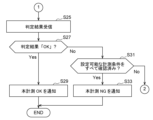
- FIG. 1 is an explanatory diagram showing a measuring device according to a first embodiment as viewed from the side; 1 is an explanatory diagram showing a measurement device according to a first embodiment as viewed from above; 1 is a block diagram showing an example of the configuration of a measurement system according to a first embodiment; 5 is a flowchart of an imaging condition setting process performed by an imaging condition setting unit of the control device according to the first embodiment. 5 is a flowchart of an imaging condition setting process performed by an imaging condition setting unit of the control device according to the first embodiment.
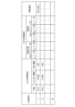
- 4 is an explanatory diagram showing an example of a list of imaging conditions according to the first embodiment; 4 is a flowchart of an autonomous driving control process performed by an autonomous driving control unit of the control device according to the first embodiment.
- 5 is a flowchart of an imaging device driving process performed by an imaging device driving unit of the control device according to the first embodiment.
- 4 is a flowchart of a self-position estimation process performed by a self-position estimation unit of the control device according to the first embodiment.
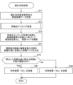
- 10 is a flowchart of an appropriateness determination process performed by a data processing unit of the information processing device according to the first embodiment.
- 10 is a flowchart of a first feature point matching process performed by a data processing unit of the information processing device according to the first embodiment.
- FIG. 4 is an explanatory diagram showing an example of a list of feature points extracted from all road surface image data by the information processing device according to the first embodiment
- FIG. 4 is an explanatory diagram showing an example of a list in which feature points extracted from all road surface image data by the information processing device according to the first embodiment are sorted (rearranged) in descending order of feature amount
- FIG. 10 is a flowchart of a model generation process by a data processing unit of the information processing device according to the first embodiment.
- 13 is a flowchart of an appropriateness determination process performed by a data processing unit of an information processing device according to a second embodiment.
- 13 is a flowchart of a second feature point matching process performed by a data processing unit of an information processing device according to a second embodiment.
- FIG. 1 is a diagram shown for explaining an example of an application of the measurement system of the present disclosure.
- the measurement system 1 includes a measurement device 10 equipped with an imaging device, and an information processing device 100 communicatively connected to the measurement device 10.
- the measurement device 10 and the information processing device 100 are communicatively connected to each other using, for example, cloud computing technology.
- the measuring device 10 captures an image of the road surface of the road R as the measurement target using an imaging device to generate road surface imaging data Img_ ⁇ , and transmits the generated road surface imaging data Img_ ⁇ to the information processing device 100 either sequentially or after imaging is completed.
- the information processing device 100 acquires the road surface imaging data Img_ ⁇ , and generates a road surface model, which is three-dimensional data showing the unevenness of the road surface, based on the acquired road surface imaging data Img_ ⁇ .
- the measurement device 10 also has multiple imaging devices arranged along a direction (left-right direction) perpendicular to the direction of movement (forward-backward direction).
- the multiple imaging devices each capture images of the road surface while the measurement device 10 autonomously travels through each of the areas D1-D3, generating multiple road surface image data Img_ ⁇ .
- the multiple imaging devices are installed so that the imaging ranges P1-P6 of adjacent imaging devices partially overlap, so that the entirety of each of the areas D1-D3 is not excluded from the imaging range.
- the moving speed of the measuring device 10 is set so that the time-series road surface image data Img_ ⁇ generated by each imaging device partially overlaps.
- the imaging range at time t_n partially overlaps with the imaging range at the previous time t_n-1 and the imaging range at the next time t_n+1.
- the imaging range of a certain calculation cycle time t_n
- time t_n may overlap with the imaging range of the calculation cycle two cycles ago or earlier (times t_n-2, t_n-3, ...), and the imaging range of the calculation cycle two cycles after or later (times t_n+2, t_n+3, ).
- FIG. 1 shows an example in which the road R to be measured extends linearly and the measuring device 10 moves in a straight line, but the shape of the object to be measured may be curved, and the example is not limited to the example in which the measuring device 10 moves in a straight line. Furthermore, the way in which the areas are divided when measuring the road R to be measured, the order in which the areas are traveled, and the course of the measuring device 10 are not limited to the above example. Furthermore, there is no particular limitation on the number of imaging devices.
- the information processing device 100 extracts feature points from the multiple road surface image data Img_ ⁇ that have been acquired, and executes feature point matching processing to align the feature points between the road surface image data Img_ ⁇ .
- the feature point matching processing is performed, for example, using SfM (Structure from Motion) processing.
- the information processing device 100 also synthesizes the multiple road surface image data Img_ ⁇ through the feature point matching processing, and generates a road surface model that indicates information on the unevenness of the road surface.
- the road surface model is generated, for example, using MVS (Multi-View Stereo) processing.
- the information processing device 100 determines whether the imaging conditions as the operating conditions of the imaging device are appropriate before starting to capture images of the road surface to generate a road surface model.
- the measurement device 10 starts capturing images of the road surface to generate a road surface model by setting the imaging conditions that are determined to be appropriate by the information processing device 100. This can improve the accuracy of the generated road surface model.
- FIGS. 2 and 3 are explanatory diagrams showing an example of the configuration of the measuring device 10.
- FIG. 2 is a side view of the measuring device 10
- FIG. 3 is a top view of the measuring device 10.
- the basic forward direction of the measuring device 10 is indicated as "front”
- the backward direction is indicated as "rear”.
- the front-rear direction, left-right direction, and height direction of the measuring device 10 refer to the front-rear direction, left-right direction, and height direction based on the "front” and "rear”.
- the measuring device 10 generates multiple road surface imaging data Img_ ⁇ by imaging the road surface as the measurement target, and transmits the generated road surface imaging data Img_ ⁇ to the information processing device 100.
- the measuring device 10 according to this embodiment is configured to be able to move on the road surface unmanned (capable of autonomous driving).
- the measuring device 10 includes a main body unit 3, an imaging unit 5, a surrounding condition detection unit 7, and a control device 50.
- the main body 3 includes a frame 11, wheels 13 (13F, 13R), a driving force source 15, and a steering device 17.
- the wheels 13 (13F, 13R), driving force source 15, and steering device 17 correspond to a driving device that moves the position of the measuring device 10.
- the frame 11 forms the skeleton of the main body 3.
- the structure and overall shape of the frame 11 shown in Figures 2 and 3 are merely examples, and the configuration of the frame 11 is not particularly limited.
- the wheels 13 include left and right front wheels 13F and rear wheels 13R.
- the driving force source 15 outputs a driving force to rotate the rear wheel 13R.
- a driving motor is a typical example of the driving force source 15, but there is no particular limitation as long as it is capable of outputting power to rotate the rear wheel 13R.
- the steering device 17 adjusts the steering angle of the front wheels 13F.
- An example of the steering device 17 is a steering device configured to rotate a pinion gear by a motor and move a rack left and right by the rotation of the pinion gear, but the configuration of the steering device 17 is not particularly limited.
- the main body 3 is not particularly limited in its specific configuration, so long as it can support the imaging unit 5 and the surrounding situation detection unit 7 and can travel while adjusting the direction of movement.
- the number of wheels 13 on the main body 3 does not need to be four, but may be three, or five or more.
- the wheels 13 that are driven to rotate by the power output from the driving force source 15 may be the front wheels 13F, or both the front wheels 13F and the rear wheels 13R may be driven to rotate.
- the driving force source 15 may be four driving motors that respectively drive the four wheels 13.
- the wheels whose steering angle is adjusted by the steering device 17 may be the rear wheels 13R, or all of the front wheels 13F and rear wheels 13R.
- the steering device can be omitted.
- the main body 3 also includes a wheel speed sensor 41.
- the wheel speed sensor 41 outputs a sensor signal corresponding to the rotation speed of the rear wheel 13R.
- the wheel speed sensor 41 may also output a sensor signal corresponding to the rotation speed of the front wheel 13F.
- the imaging unit 5 includes a plurality of imaging devices 21a-21f (hereinafter collectively referred to as imaging devices 21 unless otherwise required), irradiation lamps 25a-25f (hereinafter collectively referred to as irradiation lamps 25 unless otherwise required), and a reflector 23, and is provided at the rear of the main body 3.
- the imaging devices 21 are arranged along the left-right direction of the main body 3.
- Each imaging device 21 is installed with a uniform height and installation angle (direction of imaging).
- six imaging devices 21a to 21f are arranged at equal intervals along the left-right direction of the main body 3.
- Each imaging device 21 is installed with its imaging direction facing the road surface.
- the imaging devices 21 are installed so that the imaging ranges of adjacent imaging devices 21 overlap.
- the installation positions and installation angles of the multiple imaging devices 21 do not have to be uniform as long as the degree of overlap of the imaging ranges of adjacent imaging devices 21 can be maintained.
- the imaging directions of the imaging devices on both the left and right sides may be oriented toward the center.
- the number of imaging devices 21 is not limited to six. Furthermore, the imaging devices 21 do not have to be arranged at equal intervals. However, by arranging the imaging devices 21 at equal intervals, the relative positional relationship of the imaging data generated by adjacent imaging devices 21 becomes the same, making it easier to perform calculations.
- the irradiation lamps 25 are light sources for illuminating the road surface of the measurement target that is imaged by the imaging device 21.
- the light emitted from the irradiation lamps 25 is reflected by the reflector 23 to illuminate the road surface of the measurement target.
- the number of irradiation lamps 25 is not particularly limited as long as the brightness (illuminance or luminosity) of the road surface imaged by each imaging device 21 is uniform.
- the means for illuminating the road surface of the measurement target is not limited to the configuration example of this embodiment, and may have any configuration.
- the surrounding situation detection unit 7 has at least one sensor capable of detecting the surrounding situation of the measuring device 10.
- the surrounding situation detection unit 7 has distance measurement sensors 31a, 31b (hereinafter, collectively referred to as distance measurement sensor 31 unless a distinction is particularly required) and camera sensors 33a, 33b (hereinafter, collectively referred to as camera sensor 33 unless a distinction is particularly required).
- the distance measurement sensor 31 may be, for example, a LiDAR (Light Detection And Ranging), but may also be a radar sensor or an ultrasonic sensor.
- the camera sensor 33 has an imaging element such as a CCD or CMOS, and generates imaging data.
- the distance measuring sensors 31a and 31b are installed with the center of their measurement ranges facing the left and right front of the measurement device 10.
- the distance measuring sensors 31a and 31b are installed so that they can detect objects, such as targets, on the left and right sides of the measurement device 10.
- the camera sensors 33a and 33b are installed so that the center of their imaging ranges facing the front of the measurement device 10.
- the camera sensors 33a and 33b are installed so that they can capture a wide image of the area in front of the measurement device 10.
- the control device 50 includes one or more processors having a function for automatically moving the measuring device 10 and a function for controlling the imaging device 21, and one or more storage devices communicatively connected to the one or more processors.
- the control device 50 also includes a communication interface for communicating with the information processing device 100.
- the control device 50 is communicatively connected to various sensors and electronic control devices provided in the measuring device 10.
- control device 50 provided in the measurement device 10 will be described in detail.
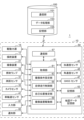
- FIG. 4 is a block diagram showing an example of the configuration of the measurement system 1.
- the control device 50 includes a processing unit 51, a storage unit 53, and a communication unit 57.
- the processing unit 51 includes one or more processors such as a CPU (Central Processing Unit) or a GPU (Graphics Processing Unit) and various peripheral components.
- a part or the whole of the processing unit 51 may be configured with updatable firmware or the like, or may be a program module or the like executed by a command from the CPU or the like.
- the processing unit 51 functions as a device that realizes the functions described below by one or more processors executing a computer program.
- the computer program is a computer program for causing the processor to execute the operations to be performed by the processing unit 51, which will be described later.
- the computer program executed by the processor may be recorded on a recording medium that functions as a storage unit (memory) 53 provided in the control device 50, or may be recorded on a recording medium built into the processing unit 51 or any recording medium that can be externally attached to the control device 50.
- Recording media for recording computer programs may include magnetic media such as hard disks, floppy disks, and magnetic tapes; optical recording media such as CD-ROMs, DVDs, and Blu-ray (registered trademark); magneto-optical media such as floptical disks; memory elements such as RAM and ROM; flash memories such as USB memory and SSDs; and other media capable of storing programs.
- the processing unit 51 is communicatively connected to the driving force source 15, steering device 17, imaging device 21, illumination lamp 25, distance measurement sensor 31, camera sensor 33, wheel speed sensor 41, input unit 81, and notification unit 83.
- the input unit 81 is a part that accepts input operations by a user.
- the input unit 81 is configured to include at least one of a keyboard, a mouse, a touchpad, and a microphone, for example.
- the type of the input unit 81 is not particularly limited.
- the notification unit 83 is a part that provides a predetermined notification to the user.
- the notification unit 83 is configured to include at least one of a display device and a speaker, for example.
- the type of the notification unit 83 is not particularly limited.
- the storage unit 53 is composed of one or more storage elements such as RAM or ROM that are communicatively connected to the processing unit 51. However, there is no particular limit to the type or number of the storage units 53.
- the storage unit 53 stores information such as computer programs executed by the processing unit 51, various parameters used in the calculation process, detection data, and calculation results. A part of the storage unit 53 is used as a work area.
- the communication unit 57 is an interface for the processing unit 51 to communicate with the information processing device 100.
- the communication unit 57 may be an interface for communicating with the information processing device 100 via mobile communication, for example, but the communication method with the information processing device 100 is not particularly limited.
- the control device 50 also includes an acceleration sensor 43, an angular velocity sensor 45, a GNSS (Global Navigation Satellite System) sensor 47, and a map data storage unit 55, all of which are communicatively connected to the processing unit 51. Note that some or all of the acceleration sensor 43, the angular velocity sensor 45, the GNSS (Global Navigation Satellite System) sensor 47, and the map data storage unit 55 may be provided separately from the control device 50.
- the acceleration sensor 43 outputs a sensor signal corresponding to the acceleration in each of the three axial directions along the front-rear, left-right, and height directions of the measuring device 10.
- the angular velocity sensor 45 outputs a sensor signal corresponding to the angular velocity around each of the three axes along the front-rear, left-right, and height directions of the measuring device 10.
- the acceleration sensor 43 and the angular velocity sensor 45 may be integrated sensors as an IMU sensor (inertial measurement unit), or may be sensors provided separately.
- the GNSS sensor 47 receives satellite signals from positioning satellites such as GPS (Global Positioning System) satellites, and transmits position information of the measuring device 10 contained in the satellite signals to the processing unit 51.
- the position information may be latitude and longitude information.
- the GNSS sensor 47 may be configured to receive satellite signals from satellite systems other than GPS satellites.
- the map data storage unit 55 is composed of a storage element such as a RAM or ROM connected to the processing unit 51 so as to be able to communicate with it, or a storage medium such as a HDD, CD, DVD, SSD, USB flash, or storage device.
- the map data stored in the map data storage unit 55 is associated with latitude and longitude information, and the processing unit 51 can identify the position of the measuring device 10 on the map data based on the latitude and longitude information of the measuring device 10 transmitted from the GNSS sensor 35.
- the processing unit 51 Before starting to capture an image of a measurement target, the processing unit 51 executes a process of setting the imaging conditions of the imaging device 21. After determining that the imaging conditions are appropriate, the processing unit 51 executes a process of starting to capture an image of the road surface with the imaging device 21 and transmitting the captured image data to the information processing device 100.
- the processing unit 51 includes an acquisition unit 61, an imaging condition setting unit 63, an autonomous driving control unit 65, a self-position estimation unit 67, and an imaging device driving unit 69.
- Each of these units is a function realized by the execution of a computer program by one or more processors.
- the acquisition unit 61, the imaging condition setting unit 63, the autonomous driving control unit 65, the self-position estimation unit 67, and the imaging device driving unit 69 may be configured using analog circuits.
- the acquisition unit 61 acquires road surface image data generated by the imaging device 21.
- the acquisition unit 61 acquires road surface image data generated by the imaging device 21 at set time intervals.
- the acquisition unit 61 also , the distance measurement sensor 31, the camera sensor 33, the wheel speed sensor 41, the acceleration sensor 43, the angular velocity sensor 45, and the GNSS sensor 47, respectively, and obtain detection data or sensor signals (hereinafter, collectively referred to as "detection information") outputted from the sensor.
- detection information detection data or sensor signals
- the imaging condition setting unit 63 sets imaging conditions as operating conditions of the imaging device 21. Specifically, the imaging condition setting unit 63 sets the moving speed of the imaging device 21, i.e., the moving speed of the measuring device 10. In addition, the imaging condition setting unit 63 sets the aperture (F-number), shutter speed, and ISO sensitivity of the imaging device 21.
- the imaging condition setting unit 63 acquires setting information of the imaging conditions of the imaging device 21 (step S11).
- the setting information of the imaging conditions may be, for example, information of parameters for setting the moving speed of the imaging device 21, and the aperture (F value), shutter speed, and ISO sensitivity of the imaging device 21.
- the setting information of the imaging conditions is stored in advance in the storage unit 53 as a list of imaging conditions in which any combination of patterns is set, and the imaging condition setting unit 63 acquires any imaging condition from the list of imaging conditions.
- FIG. 7 is an explanatory diagram showing an example of a list of imaging conditions.
- Each of the imaging conditions (1, 2...N) includes information on the setting values of the F-number, shutter speed, and ISO sensitivity of the imaging device 21.
- Each of the imaging conditions (1, 2...N) also includes information on the movement speed of the imaging device 21.
- the F-number, shutter speed, and ISO sensitivity settings of the imaging device 21 are set as multiple possible combinations based on the specifications of the imaging device 21, etc.
- the reference position ( x0 , y0 , z0 ) may be, for example, the position of the center of gravity of the measurement device 10, or may be the reference position of any one of the imaging devices 21 among the multiple imaging devices 21a to 21f.
- the z coordinates (heights) of all the imaging devices 21 in the device coordinate system are unified at a predetermined reference distance, so the information on the installation positions of the imaging devices 21 does not include z coordinate information. If the heights of the imaging devices 21 are different, the information on the installation positions of the imaging devices 21 may include z coordinate information.
- the moving speed of the imaging devices 21 is set to a moving speed at which the imaging ranges of the road surface imaging data acquired in time series partially overlap, based on the length of the road surface corresponding to the pixel size of the road surface imaging data captured by each imaging device 21 and the time interval between images captured by the imaging devices 21.
- the imaging condition setting unit 63 may set one of the imaging conditions from the list of imaging conditions according to a preset priority order, may acquire one of the imaging conditions randomly, or may acquire one of the imaging conditions according to a predetermined order.
- the imaging condition setting unit 63 sets the measurement device 10 according to the acquired imaging condition setting information (step S13).
- the user may manually set some or all of the acquired imaging conditions. For example, the user may hold each imaging device 21 and adjust the installation position and rotation angle of the imaging device 21 while checking the position of the imaging device 21 on the device coordinate system and the measurement values of a digital meter that can measure the rotation angle around the three axes of the device coordinate system. The user may also manually adjust some or all of the F-number, shutter speed, and ISO sensitivity of the imaging device 21.
- the imaging condition setting unit 63 determines whether the set imaging target area is an area distant from the current position of the measurement device 10 (step S17). For example, the imaging condition setting unit 63 may determine that the set imaging target area is an area distant from the current position of the measurement device 10 when the position coordinates indicated by the position information of the measurement device 10 output from the GNSS sensor 47 are not located within the imaging target area. The imaging condition setting unit 63 may also determine that the imaging target area is an area distant from the current position of the measurement device 10 based on user input.
- the imaging condition setting unit 63 does not determine that the set imaging target area is an area far from the current position of the measuring device 10 (S17/No), it proceeds to step S21. On the other hand, if the imaging condition setting unit 63 determines that the set imaging target area is an area far from the current position of the measuring device 10 (S17/Yes), it moves the measuring device 10 to the imaging target area (step S19).
- the imaging condition setting unit 63 may notify the user to manually move the measuring device 10 to the imaging target area, or may output a command to the autonomous driving control unit 65 to move the measuring device 10 to the imaging target area.
- the imaging condition setting unit 63 starts acquiring road surface imaging data Img_ ⁇ while the measuring device 10 is positioned in the imaging target area (step S21).
- the autonomous driving control unit 65 moves the measuring device 10 along a predetermined movement path at the set movement speed.
- the imaging condition setting unit 63 determines that all imaging conditions set in the list of imaging conditions have been checked (S31/Yes), it activates the notification unit 83 to notify that the measurement device 10 cannot measure the road surface (main measurement) because no imaging conditions that provide the accuracy or reliability of the measurement results were found (step S33). In this case, there is a risk that some abnormality has occurred in the measurement device 10, so the user can take action such as inspection, repair, replacement, etc. as necessary.
- the imaging condition setting unit 63 determines that all imaging conditions set in the list of imaging conditions have been confirmed (S31/No), it returns to step S11, sets the next imaging condition, and performs suitability determination according to the procedure described above.
- the imaging condition setting unit 63 determines that the judgment result is "OK" (S29/Yes), it drives the notification unit 83 to notify that the set imaging conditions are appropriate and that it is OK to start measuring the road surface (main measurement) by the measuring device 10 (step S29). This allows the user to start measuring the road surface of the measurement target.
- the autonomous driving control unit 65 preferentially uses the detection information output from the distance measurement sensor 31 and moves the measuring device 10 along the guide information detected by the distance measurement sensor 31.
- Guide information refers to three-dimensional objects installed along the road, such as side walls, curbs, and guardrails, which can serve as a reference when moving the measuring device 10 along the direction in which the road extends.
- the autonomous driving control unit 65 executes a process of moving the measuring device 10 along the road while maintaining the distance between such guide information and the measuring device 10 at a predetermined set distance.
- the measuring device 10 of this embodiment is configured on the premise that the object detection accuracy and the measurement accuracy of the distance to the object measured by the distance sensor 31 are higher than the measurement accuracy of the object and the distance to the object measured by the camera sensor 33.
- the priority of the sensors used by the autonomous driving control unit 65 may differ depending on the measurement accuracy of each sensor.
- the autonomous driving control unit 65 when it is no longer able to move the measuring device 10 along the guide information detected using the distance sensor 31 or the camera sensor 33, it may move the measuring device 10 along a predetermined course based on the position of the measuring device 10 (self-position, odometry information) estimated by the self-position estimation unit 67 described later.
- the autonomous driving control unit 65 acquires information on the current position (x, y) and moving direction of the measuring device 10 (step S43). For example, the autonomous driving control unit 65 acquires position information (latitude and longitude information) output from the GNSS sensor 47.
- the autonomous driving control unit 65 may acquire information on the current position (x, y) of the measuring device 10 on a predetermined two-dimensional coordinate system based on information on the distance from the measuring device 10 to the guide information and odometry information estimated by the self-position estimation unit 67 described later.
- the autonomous driving control unit 65 also acquires information on the movement direction of the measuring device 10 along with information on the current position of the measuring device 10. For example, the autonomous driving control unit 65 determines the direction of a vector connecting the position information of the measuring device 10 on the map data in the previous calculation cycle (t_n-1) and the position information of the measuring device 10 on the map data in the current calculation cycle (t_n) as the movement direction. The autonomous driving control unit 65 may also acquire information on the movement direction of the measuring device 10 from odometry information estimated by the self-position estimation unit 67 described later.
- the autonomous driving control unit 65 controls the driving of the driving force source 15 and the steering device 17 according to the driving amount set in step S45 (step S47).
- the autonomous driving control unit 65 determines whether or not the measurement has ended (step S49). For example, the autonomous driving control unit 65 determines that the measurement has ended when the measuring device 10 has reached the measurement end position. Alternatively, the autonomous driving control unit 65 may determine that the measurement has ended when an emergency stop operation is performed by the user, etc.
- the autonomous driving control unit 65 If the autonomous driving control unit 65 does not determine that the measurement has ended (S49/No), it returns to step S43 and continues controlling the autonomous driving of the measuring device 10. On the other hand, if the autonomous driving control unit 65 determines that the measurement has ended (S49/Yes), it ends the autonomous driving control process.
- the self-position estimation unit 67 estimates odometry information including the position of the measurement device 10 on a predetermined three-dimensional coordinate system (hereinafter, also referred to as the "self-position"). For example, the self-position estimation unit 67 estimates odometry information including the position of the measurement device 10 on a predetermined three-dimensional coordinate system (hereinafter, also referred to as the "self-position"). 41, the measurement device 10 when starting the measurement process based on time series data of the moving speed, the acceleration in the three axial directions, and the angular velocity around the three axial directions of the measurement device 10 detected by the acceleration sensor 43 and the angular velocity sensor 45. The change in the position (self-position) of the measuring device 10 based on the position of the measuring device 10 is calculated.
- FIG. 10 shows a flowchart of the self-location estimation process performed by the self-location estimation unit 67.
- the self-position estimation unit 67 records a start position (step S51).
- the start position is a reference position when calculating the position of the measurement device 10.
- the self-position estimation unit 67 records the position coordinates of the reference position ( x0 , y0 , z0 ) of the measurement device 10 at the start of the measurement process as the start position.
- the recorded reference position does not need to be specified by specific latitude and longitude information, and may be recorded as an arbitrary point of arbitrary three-dimensional coordinates (for example, the origin of a three-dimensional coordinate system).
- the self-position estimation unit 67 may record the latitude and longitude information of the reference position ( x0 , y0 ) of the measuring device 10 as the x-coordinate and y-coordinate of the starting position.
- the self-position estimation unit 67 acquires detection information from the wheel speed sensor 41, the acceleration sensor 43, and the angular velocity sensor 45 (step S53).
- the detection information from the acceleration sensor 43 includes information indicating the acceleration in three axial directions along the front-rear, left-right, and height directions of the measurement device 10.
- the detection information from the angular velocity sensor 45 includes information indicating the angular velocity around three axes along the front-rear, left-right, and height directions of the measurement device 10.
- the self-position estimation unit 67 may correct the position and orientation of the measuring device 10 based on measurement data from at least one of the distance measurement sensor 31 and the camera sensor 33. For example, the self-position estimation unit 67 may correct the position of the measuring device 10 based on the distance between the measuring device 10 and a stationary object detected by the distance measurement sensor 31 or the camera sensor 33, and the change over time in the position (direction) of the stationary object as viewed from the measuring device 10.
- the self-position estimation unit 67 may correct the position of the measuring device 10 based on the position information output from the GNSS sensor 47.
- the self-position estimation unit 67 may correct the position of the measuring device 10 based on a change over time in the position information output from the GNSS sensor 47.
- the self-position estimation unit 67 records the data of the position of the measuring device 10 (position coordinates of the self-position) P_n (x_n, y_n) calculated in the current calculation cycle (t_n) in the memory unit 53 (step S57).
- the self-position estimation unit 67 determines whether or not the measurement has ended (step S59). For example, the self-position estimation unit 67 determines that the measurement has ended when the measuring device 10 has reached the measurement end position. Alternatively, the self-position estimation unit 67 may determine that the measurement has ended when an emergency stop operation is performed by the user or the like.
- the self-position estimation unit 67 determines that the measurement has ended (S59/No)
- the process returns to step S53 and continues the self-position estimation process of the measuring device 10.
- the self-position estimation unit 67 determines that the measurement has ended (S59/Yes)
- the self-position estimation process ends.
- the self-position estimation unit 67 may estimate the odometry information by further taking into account the amount of drive of the drive power source 15 and the steering device 17 by the autonomous driving control unit 65, and may estimate the odometry information by further taking into account changes in the position information of the measuring device 10 output from the GNSS sensor 47.
- the imaging device driving unit 69 controls driving of the imaging device 21.
- the imaging device driving unit 69 controls imaging by the imaging device 21 in accordance with the imaging conditions (aperture (F-number), shutter speed, and ISO sensitivity) that are set by the imaging condition setting unit 63 and determined to be appropriate.
- FIG. 9 is a flowchart showing the imaging device driving process performed by the imaging device driving section 69 .
- the imaging device driving unit 69 acquires the imaging conditions (aperture (F-number), shutter speed, and ISO sensitivity) set by the imaging condition setting unit 63 (step S61).
- the imaging device driving unit 69 controls the driving of the imaging device 21 (step S63).
- the imaging device driving unit 69 controls the driving of the imaging device 21 under the set imaging conditions, and executes a process of imaging the road surface to be measured.
- the imaging device driving unit 69 determines whether or not the measurement has ended (step S67). For example, the imaging device driving unit 69 determines that the measurement has ended when the autonomous driving control has ended. Alternatively, the imaging device driving unit 69 may determine that the measurement has ended when an emergency stop operation is performed by the user, etc.
- the imaging device driving unit 69 If the imaging device driving unit 69 does not determine that the measurement has ended (S67/No), it returns to step S63 and continues driving the imaging device 21. On the other hand, if the imaging device driving unit 69 determines that the measurement has ended (S67/Yes), it ends the imaging device driving process.
- the information processing device 100 includes a communication unit 101, a data processing unit 103, and a storage unit 105.
- the communication unit 101 is an interface for the data processing unit 103 to communicate with the control device 50.
- the communication unit 101 may be an interface for communicating with the control device 50 via mobile communication, for example, but the communication method with the control device 50 is not particularly limited.
- the data processing unit 103 is configured with one or more processors, such as a CPU (Central Processing Unit) or a GPU (Graphics Processing Unit), and various peripheral components.
- processors such as a CPU (Central Processing Unit) or a GPU (Graphics Processing Unit), and various peripheral components.
- a part or all of the processing unit 51 may be configured with updatable components, such as firmware, or may be a program module executed by commands from a CPU, etc.
- the data processing unit 103 functions as a device that realizes the functions described below by one or more processors executing a computer program.
- the computer program is a computer program for causing the processor to execute the operations to be performed by the data processing unit 103, which will be described later.
- the computer program executed by the processor may be recorded on a recording medium that functions as a storage unit (memory) 105 provided in the information processing device 100, or may be recorded on a recording medium built into the data processing unit 103 or any recording medium that can be attached externally to the information processing device 100.
- Recording media for recording computer programs may include magnetic media such as hard disks, floppy disks, and magnetic tapes; optical recording media such as CD-ROMs, DVDs, and Blu-ray (registered trademark); magneto-optical media such as floptical disks; memory elements such as RAM and ROM; flash memories such as USB memory and SSDs; and other media capable of storing programs.
- the storage unit 105 is composed of one or more storage elements such as RAM or ROM, or storage media such as HDD or SSD, communicably connected to the data processing unit 103. However, there is no particular limit to the type or number of the storage units 105.
- the storage unit 105 stores information such as computer programs executed by the data processing unit 103, various parameters used in arithmetic processing, detection data, and calculation results. A part of the storage unit 105 is used as a work area.
- the data processing unit 103 executes a suitability determination process for determining whether the imaging conditions are suitable or not using the road surface imaging data Img_ ⁇ .
- the data processing unit 103 determines whether the imaging conditions are suitable or not using the road surface imaging data Img_ ⁇ of the imaging target area set for setting the imaging conditions.
- FIG. 12 shows a flowchart of the first feature point matching process.
- the method for extracting feature points from image data may be a conventionally known method, and therefore a detailed description thereof will be omitted.
- the data processing unit 103 defines the horizontal direction of the road surface image data Img_ ⁇ as the x-axis and the vertical direction as the y-axis, and defines the position of the pixel corresponding to the feature point as the position (x, y) of the feature point.
- the data processing unit 103 selects a preset number of feature points from the extracted feature points in descending order of feature amount (step S93).
- the number of feature points to be selected may be set arbitrarily, but is set to an appropriate number in order to determine whether the set imaging conditions are appropriate.
- the number of feature points to be selected may be set according to a ratio such as one-third of the extracted feature points in descending order of feature amount.
- the process of matching feature points between imaging data may be executed using a conventionally known method, and therefore a detailed description will be omitted.
- the data processing unit 103 generates a distance map by converting the calculated parallax value into a distance value between the road surface and the image capture device 21 (step S77). Specifically, the data processing unit 103 converts the parallax value d into a distance (estimated distance) Z value from the road surface to the image capture device 21 using the following formula (1).
- Z f ⁇ b/d...(1)
- the distance Z from the road surface to the imaging device 21 is the shortest distance from the road surface to the imaging device 21. Specifically, the distance Z from the road surface to the imaging device 21 corresponds to the distance from the road surface to the center of the lens of the imaging device 21.
- the data processing unit 103 determines whether the difference between the calculated distance Z value and the distance value of the measurement device 10 specification is within a predetermined threshold value (step S79).
- the distance of the measurement device 10 specification is the distance in the z-axis direction of the device coordinate system from the center of the lens of the imaging device 21 to the contact surface of the wheels 13 of the measurement device 10, which is calculated based on the height of the installation position of the imaging device 21 in the measurement device 10.
- Information on the distance of the specification is recorded in advance in the storage unit 53.
- the predetermined threshold value may be a value set based on the size of unevenness that can be expected on the surface to be measured.
- the data processing unit 103 determines the determination result as "NG” and transmits the determination result to the control device 50 (step S83). If the difference between the calculated distance Z value and the distance value of the measurement device 10 specifications exceeds the predetermined threshold value, it is considered that the set imaging conditions are not appropriate.
- the data processing unit 103 determines that the difference between the calculated distance Z value and the distance value of the measurement device 10 specifications is within a predetermined threshold value (S79/Yes), it sets the determination result as "OK” and transmits the determination result to the control device 50 (step S81).
- the data processing unit 103 ends the suitability determination process by transmitting the determination result to the control device 50 in step S81 or step S83.
- Model generation process 15 is a flowchart of a model generation process performed by the data processing unit 103. Note that the flowchart shown below illustrates an example in which the control device 50 sequentially transmits the road surface image data Img_ ⁇ captured by the imaging device 21 to the information processing device 100 at predetermined calculation intervals.
- a feature point may be a point where the amount of change in luminance (feature value) between adjacent pixels in the road surface imaging data Img_ ⁇ _n is equal to or greater than a predetermined threshold value, but other feature values may also be used.
- the method for extracting feature points from imaging data may be a conventionally known method, so a detailed description will be omitted.
- the data processing unit 103 constructs three-dimensional point cloud data by MVS (Multi-View Stereo) processing, and generates a road surface model.
- MVS Multi-View Stereo
- the method of generating a road surface model composed of three-dimensional point cloud data is not particularly limited.
- the data processing unit 103 determines whether or not to end the model generation process (step S109). For example, the data processing unit 103 may determine to end the model generation process when a predetermined time has elapsed since the control device 50 stopped transmitting road surface imaging data Img_ ⁇ . Alternatively, the data processing unit 103 may determine to end the model generation process when the control device 50 transmits a signal indicating the end of measurement.
- the data processing unit 103 If the data processing unit 103 does not determine that the model generation process should be terminated (S109/No), the data processing unit 103 returns to step S101 and continues the model generation process. On the other hand, if the data processing unit 103 determines that the model generation process should be terminated (S109/Yes), the data processing unit 103 terminates the model generation process.
- the measurement system 1 can capture images of the road surface while autonomously driving the measurement device 10 equipped with an imaging device along a measurement route based on guide information in order to obtain road surface imaging data for generating a road surface model. Furthermore, before the measurement device 10 starts the actual measurement, the measurement system 1 can use imaging data captured of a target area set on the road surface to be measured to perform a simple method of determining whether the imaging conditions of the imaging device are appropriate for obtaining imaging data suitable for generating a road surface model. Therefore, appropriate imaging conditions can be determined before actually generating a road surface model.
- the control device 50 when the information processing device 100 transmits to the control device a result of suitability judgment indicating that the imaging conditions are not suitable, the control device 50 automatically changes the imaging conditions, captures the image again, and transmits the imaging data to the information processing device 100. Therefore, the control device 50 can automatically change the settings of the imaging conditions until suitable imaging conditions are found.
- the measurement system according to the second embodiment differs from the measurement system according to the first embodiment in the suitability determination process executed by the data processing unit 103 of the information processing device 100.
- the method for extracting feature points from image data may be a conventionally known method, so a detailed description will be omitted.
- step S75 to S79 the construction of a parallax map and the generation of a distance map are sequentially performed in the same procedure as steps S75 to S79 described in the first embodiment, and it is determined whether the difference between the calculated distance Z value and the distance value of the measurement device 10 specifications is within a predetermined threshold value (steps S75 to S79).
- the data processing unit 103 determines whether or not all settable image resolutions have been confirmed (step S85). In the above example, the data processing unit 103 determines whether or not the appropriateness of all settable image resolutions in the four levels of 1/16, 1/8, 1/4, and 1/2 has been confirmed.
- step S73 If the data processing unit 103 does not determine that all settable image resolutions have been checked (S85/No), it returns to step S73, sets one of the unset image resolutions, and performs an appropriateness determination according to the procedure described above. If the difference between the calculated distance Z value and the distance value of the measurement device 10 specifications exceeds a predetermined threshold, the set image resolution is considered to be inappropriate, and the data processing unit 103 attempts to adjust the image resolution before changing the imaging conditions.
- the data processing unit 103 determines that all settable image resolutions have been checked (S85/Yes), it determines the result as "NG” and transmits the result to the control device 50 (step S83). Even if the image resolution settings have been changed, if the difference between the calculated distance Z value and the distance value of the measurement device 10 specifications exceeds a predetermined threshold, the set imaging conditions are considered to be inappropriate.
- the data processing unit 103 determines that the difference between the calculated distance Z value and the distance value of the measurement device 10 specifications is within a predetermined threshold value (S79/Yes), it determines the determination result as "OK” and transmits the determination result together with information on the image resolution at the time the determination result became "OK” to the control device 50 (step S87).
- the control device 50 maintains the imaging conditions that were set, and sets the image resolution of the road surface imaging data Img_ ⁇ to be generated to the image resolution received from the information processing device 100.
- the data processing unit 103 ends the suitability determination process by transmitting the determination result to the control device 50 in step S87 or step S83.
- the rest of the configuration of the measurement system according to this embodiment may be configured similarly to the configuration of the measurement system 1 according to the first embodiment, so detailed explanation will be omitted.
- the information processing device 100 changes the image resolution and re-executes the appropriateness determination of the imaging conditions before changing the imaging conditions. Therefore, during the appropriateness determination of the imaging conditions, it is possible to determine appropriate imaging conditions that match the shooting environment of the measurement target without changing the set imaging conditions.
- the moving speed of the imaging device, the F-number, the shutter speed, and the ISO sensitivity are set as the imaging conditions, but the imaging conditions are not limited to the above examples.
- the imaging conditions may also include the output (illuminance or brightness) of the illumination lamp. This can further improve the matching accuracy of feature points.
- the measurement system of the above embodiment is configured as a measurement system that generates a three-dimensional model of the unevenness of the road surface as the measurement target, but the measurement target is not limited to the road surface and may be any measurement target.
- the measurement device used in the measurement system of the above embodiment is configured as a measurement device that can travel on the road surface, but the measurement device may be configured as an unmanned or manned flying object. In this case, the measurement device identifies its own position and orientation in three-dimensional space, making it possible to calculate the imaging range of each imaging data, the distance from the imaging device to the measurement target, etc., and the technology disclosed herein can be applied.
- the measurement system of the above embodiment is configured by a measurement device that mainly acquires imaging data and an information processing device that mainly performs data processing, which are connected so as to be able to communicate with each other, but the technology of the present disclosure is not limited to the above example.
- Some of the functions of the data processing unit of the information processing device may be provided in the measurement device.
- the information processing device may be mounted in the measurement device, or all of the functions of the data processing unit of the information processing device may be provided in the control device of the measurement device, and the measurement system may be configured only by the measurement device.
- the technology disclosed herein can also be realized as an information processing device applied to the measurement system 1, a control method executed by the control device, an information processing method executed by the information processing device, a computer program that causes a computer to function as at least one of the control device and the information processing device, and a non-transitory tangible recording medium on which the computer program is recorded.
- Measurement system 10 Measurement device 13: Wheel 15: Driving force source 17: Steering device 21: Imaging device 23: Reflector 25: Illumination lamp 27: Illumination lamp 31: Distance measurement sensor 33: Camera sensor 35: GNSS sensor 41: Wheel speed sensor 43: Acceleration sensor 45: Angular velocity sensor 47: GNSS sensor 50: Control device 51: Processing unit 53: Memory unit 55: Map data memory unit 57: Communication unit 61: Acquisition unit 63: Imaging condition setting unit 65: Autonomous driving control unit 67: Self-position estimation unit 69: Imaging device driving unit 81: Input unit 83: Notification unit 100: Information processing device 101: Communication unit 103: Data processing unit 105: Memory unit 113: Data processing unit
Landscapes
- Physics & Mathematics (AREA)
- General Physics & Mathematics (AREA)
- Electromagnetism (AREA)
- Engineering & Computer Science (AREA)
- Radar, Positioning & Navigation (AREA)
- Remote Sensing (AREA)
- Traffic Control Systems (AREA)
Abstract
Description
はじめに、本開示の実施形態に係る計測システムの概要を説明する。
図1に示した例において、計測システム1は、撮像装置を搭載した計測装置10と、計測装置10と通信可能に接続された情報処理装置100とを備えている。計測装置10と情報処理装置100とは、例えばクラウドコンピューティングの技術を用いて通信可能に接続される。
以下、本開示の第1の実施の形態に係る計測システム1を具体的に説明する。
まず、本実施形態に係る計測システム1に用いられる計測装置10の構成例を説明する。
続いて、計測装置10に備えられた制御装置50を詳しく説明する。
図4は、計測システム1の構成例を示すブロック図である。
制御装置50は、処理部51、記憶部53及び通信部57を備えている。処理部51は、CPU(Central Processing Unit)又はGPU(Graphics Processing Unit)等の一つ又は複数のプロセッサや種々の周辺部品を備えて構成される。処理部51の一部又は全部は、ファームウェア等の更新可能なもので構成されてもよく、また、CPU等からの指令によって実行されるプログラムモジュール等であってもよい。
続いて、処理部51の構成を説明する。
処理部51は、計測対象の撮像を開始する前に撮像装置21の撮像条件を設定する処理を実行する。また、処理部51は、撮像条件が適正であると判定された後に、撮像装置21により路面の撮像を開始し、撮像データを情報処理装置100へ送信する処理を実行する。
取得部61は、撮像装置21により生成された路面撮像データを取得する。取得部61は、設定された時間間隔で撮像装置21により生成された路面撮像データを取得する。また、取得部61は、測距センサ31、カメラセンサ33、車輪速センサ41、加速度センサ43、角速度センサ45及びGNSSセンサ47それぞれから出力される検出データあるいはセンサ信号(以下、まとめて「検出情報」ともいう)を取得する。取得部61は、所定の演算周期ごとにそれぞれのセンサから出力される検出情報を取得する。
撮像条件設定部63は、撮像装置21の作動条件としての撮像条件を設定する。具体的に、撮像条件設定部63は、撮像装置21の移動速度、すなわち、計測装置10の移動速度を設定する。また、撮像条件設定部63は、撮像装置21の絞り(F値)、シャッター速度及びISO感度を設定する。
図5~図6は、撮像条件設定部63による撮像条件設定処理のフローチャートを示す。
本実施形態において、撮像条件設定部63は、撮像装置21の撮像条件の設定情報を取得する(ステップS11)。撮像条件の設定情報は、例えば撮像装置21の移動速度、及び、撮像装置21の絞り(F値)、シャッター速度並びにISO感度を設定するためのパラメータの情報であってよい。撮像条件の設定情報は、任意の組み合わせのパターンを設定した撮像条件のリストとしてあらかじめ記憶部53に格納され、撮像条件設定部63は、撮像条件のリストのなかからいずれかの撮像条件を取得する。
それぞれの撮像条件(1,2・・・N)は、撮像装置21のF値、シャッター速度及びISO感度の設定値の情報を含む。また、それぞれの撮像条件(1,2・・・N)は、それぞれの撮像装置21a~21fの設置位置(x0_α,y0_α:α=1,2・・・N)及び回転角(θ_α,ψ_α,ε_α:α=1,2・・・N)の情報を含む。また、それぞれの撮像条件(1,2・・・N)は、撮像装置21の移動速度の情報を含む。
自律走行制御部65は、計測装置10の自律走行を制御する。自律走行とは、制御装置50が検出情報に基づいて駆動力源15及び操舵装置17の駆動を制御することにより、計測装置10が所定の目標経路に沿って移動する走行状態をいう。
図8は、自律走行制御部65による計測装置10の自律走行制御処理の一例を示すフローチャートである。
自律走行制御部65は、計測経路の情報を取得する(ステップS41)。計測経路は、少なくとも計測開始位置及び計測終了位置の情報を含む。GNSSセンサ47から出力される位置情報を用いて計測装置10を自律走行させる場合、撮像条件設定部63は、例えば計測装置10の現在位置を計測開始位置とし、計測終了位置の情報を取得して、地図データを参照して計測開始位置から計測終了位置までの計測経路を道路に沿って設定する。
自己位置推定部67は、所定の三次元座標系上での計測装置10の位置(以下、「自己位置」ともいう)を含むオドメトリ情報を推定する。例えば自己位置推定部67は、車輪速センサ41、加速度センサ43及び角速度センサ45により検出される計測装置10の移動速度、三軸方向の加速度及び三軸の軸周りの角速度の時系列データに基づいて、計測処理を開始するときの計測装置10の位置を基準とする計測装置10の位置(自己位置)の変化を算出する。
図10は、自己位置推定部67による自己位置推定処理のフローチャートを示す。
自己位置推定部67は、開始位置を記録する(ステップS51)。開始位置は、計測装置10の位置を算出する際の基準となる位置である。例えば自己位置推定部67は、計測処理の開始時の計測装置10の基準位置(x0,y0,z0)の位置座標を開始位置として記録する。なお、記録される基準位置は、具体的な緯度及び経度の情報により特定される必要はなく、任意の三次元座標の任意の点(例えば三次元座標系の原点)として記録されてよい。
撮像装置駆動部69は、撮像装置21の駆動を制御する。撮像装置駆動部69は、撮像条件設定部63により設定され、適正と判定された撮像条件(絞り(F値)、シャッター速度及びISO感度)にしたがって撮像装置21による撮像を制御する。
図9は、撮像装置駆動部69による撮像装置駆動処理のフローチャートを示す。
撮像装置駆動部69は、撮像条件設定部63により設定された撮像条件(絞り(F値)、シャッター速度及びISO感度)を取得する(ステップS61)。次いで、撮像装置駆動部69は、撮像装置21の駆動を制御する(ステップS63)。例えば撮像装置駆動部69は、自律走行制御部65による計測装置10の自律走行制御の実行中に、設定された撮像条件で撮像装置21の駆動を制御し、計測対象の路面を撮像する処理を実行する。
続いて、情報処理装置100を詳しく説明する。
図4に示したように、情報処理装置100は、通信部101、データ処理部103及び記憶部105を備えている。通信部101は、データ処理部103が制御装置50との間で通信を行うためのインタフェースである。通信部101は、例えば移動体通信を介して制御装置50と通信を行うためのインタフェースであってよいが、制御装置50との通信方式は特に限定されるものではない。
データ処理部103は、路面撮像データImg_αとともに撮像条件の適正判定を要求する信号を受信した場合、路面撮像データImg_αを用いて撮像条件が適正か否かを判定する適正判定処理を実行する。データ処理部103は、撮像条件の設定のために設定された撮像対象領域の路面撮像データImg_αを用いて撮像条件が適正か否かの判定を行う。
図11は、データ処理部103による適正判定処理のフローチャートを示す。
データ処理部103は、撮像条件の適正判定を要求する信号とともに路面撮像データImg_α(α=1,2・・・M)を受信する(ステップS71)。次いで、データ処理部103は、取得した路面撮像データImg_α(α=1,2・・・M)を用いて特徴点マッチング処理を実行する(ステップS73)。本実施形態では、データ処理部103は、適正判定処理を実行する場合、それぞれの路面撮像データImg_α(α=1,2・・・M)から抽出される特徴点のうち、特徴量が大きい順に所定数の特徴点を選択し、路面撮像データImg_α(α=1,2・・・M)で選択した特徴点をマッチングする第1の特徴点マッチング処理を実行する。
データ処理部103は、受信したそれぞれの路面撮像データImg_α(α=1,2・・・M)から特徴点を抽出する(ステップS91)。特徴点は、例えば路面撮像データImg_α(α=1,2・・・M)において、隣り合うピクセル間の輝度の変化量(特徴量)が所定の閾値以上となる点であってよいが、他の特徴量を用いてもよい。撮像データから特徴点を抽出する方法は従来公知の方法であってよいため、詳しい説明は省略する。
Z:路面から撮像装置21までの距離
f:撮像装置21の焦点距離f
b:隣り合う撮像装置21間の距離
d:視差値
図15は、データ処理部103によるモデル生成処理のフローチャートを示す。なお、以下に示すフローチャートは、制御装置50が所定の演算周期ごとに撮像装置21により撮像した路面撮像データImg_αを情報処理装置100へ逐次送信する例を示す。
続いて、本開示の第2の実施の形態に係る計測システムを説明する。
データ処理部103は、撮像条件の適正判定を要求する信号とともに路面撮像データImg_α(α=1,2・・・M)を受信する(ステップS71)。次いで、データ処理部103は、取得した路面撮像データImg_α(α=1,2・・・M)を用いて特徴点マッチング処理を実行する(ステップS73)。本実施形態では、データ処理部103は、適正判定処理を実行する場合、取得した路面撮像データImg_α(α=1,2・・・M)の画像解像度を変更し、路面撮像データImg_α(α=1,2・・・M)から抽出される特徴点をマッチングする第2の特徴点マッチング処理を実行する。
データ処理部103は、取得した路面撮像データImg_α(α=1,2・・・M)の画像解像度を設定する(ステップS111)。例えば画像解像度は、1/16、1/8、1/4及び1/2の四段階で設定可能であり、データ処理部103は、いずれかの画像解像度に設定する。
10 :計測装置
13 :車輪
15 :駆動力源
17 :操舵装置
21 :撮像装置
23 :リフレクタ
25 :照射ランプ
27 :照射ランプ
31 :測距センサ
33 :カメラセンサ
35 :GNSSセンサ
41 :車輪速センサ
43 :加速度センサ
45 :角速度センサ
47 :GNSSセンサ
50 :制御装置
51 :処理部
53 :記憶部
55 :地図データ記憶部
57 :通信部
61 :取得部
63 :撮像条件設定部
65 :自律走行制御部
67 :自己位置推定部
69 :撮像装置駆動部
81 :入力部
83 :通知部
100 :情報処理装置
101 :通信部
103 :データ処理部
105 :記憶部
113 :データ処理部
Claims (7)
- 計測対象を撮像した複数の撮像データを合成し、前記計測対象のモデルのデータを生成する計測システムにおいて、
前記計測対象を撮像し前記撮像データを生成する撮像装置と、
前記撮像装置を制御する制御装置と、
前記撮像装置により撮像された複数の前記撮像データを取得し、取得した前記複数の撮像データを合成して前記計測対象のモデルのデータを生成する情報処理装置と、を備え、
前記制御装置は、
前記撮像装置の作動条件としての所定の撮像条件を設定する撮像条件設定処理と、
設定した前記撮像条件の下で前記計測対象に設定された所定の撮影対象領域を前記撮像装置により撮像した複数の前記撮像データを生成して前記情報処理装置へ送信する撮像装置駆動処理と、を実行し、
前記情報処理装置は、
前記制御装置から送信される前記複数の撮像データを取得し、取得した前記複数の撮像データからそれぞれ抽出される特徴点をマッチングする特徴点マッチング処理と、
前記特徴点マッチング処理の結果に基づいて前記撮像装置と前記計測対象との間の推定距離を算出し、算出した前記推定距離と所定の基準距離とに基づいて前記撮像条件の適正判定を行う適正判定処理と、を実行する、
計測システム。 - 前記情報処理装置は、
前記特徴点マッチング処理において、それぞれの前記撮像データから抽出される特徴点のうち、特徴量が大きい順に所定数の前記特徴点を選択し、選択した前記特徴点をマッチングする、
請求項1に記載の計測システム。 - 前記情報処理装置は、
前記特徴点マッチング処理において、前記撮像データの画像解像度を調節して前記特徴点をマッチングする、
請求項2に記載の計測システム。 - 前記情報処理装置は、前記適正判定処理の結果を前記制御装置へ送信し、
前記制御装置は、前記情報処理装置から前記撮像条件が適正でないことを示す前記適正判定の結果を受信した場合、前記撮像条件の設定を変更して前記撮像装置により前記計測対象を撮影した複数の前記撮像データを生成して前記情報処理装置へ送信する、
請求項1に記載の計測システム。 - 計測対象を撮像した複数の撮像データを合成し、前記計測対象のモデルのデータを生成する情報処理装置において、
撮像装置の作動条件として設定される所定の撮像条件の下で前記計測対象に設定された所定の撮影対象領域を前記撮像装置により撮像した複数の撮像データを取得し、取得した前記複数の撮像データからそれぞれ抽出される特徴点をマッチングする特徴点マッチング処理と、
前記特徴点マッチング処理の結果に基づいて前記撮像装置と前記計測対象との間の推定距離を算出し、算出した前記推定距離と所定の基準距離とに基づいて前記撮像条件の適正判定を行う適正判定処理と、
を実行する、情報処理装置。 - 計測対象を撮像した複数の撮像データを合成し、前記計測対象のモデルのデータを生成する情報処理方法において、
コンピュータが、
撮像装置の作動条件として設定される所定の撮像条件の下で前記計測対象に設定された所定の撮影対象領域を前記撮像装置により撮像した複数の撮像データを取得し、取得した前記複数の撮像データからそれぞれ抽出される特徴点をマッチングすることと、
前記特徴点マッチング処理の結果に基づいて前記撮像装置と前記計測対象との間の推定距離を算出し、算出した前記推定距離と所定の基準距離とに基づいて前記撮像条件の適正判定を行うことと、
を含む処理を実行する、情報処理方法。 - コンピュータに、
撮像装置の作動条件として設定される所定の撮像条件の下で前記計測対象に設定された所定の撮影対象領域を前記撮像装置により撮像した複数の撮像データを取得することと、
取得した前記複数の撮像データからそれぞれ抽出される特徴点をマッチングする特徴点マッチング処理と、
前記特徴点マッチング処理の結果に基づいて前記撮像装置と前記計測対象との間の推定距離を算出し、算出した前記推定距離と所定の基準距離とに基づいて前記撮像条件の適正判定を行うことと、
を含む処理を実行させるプログラムを記録した、非一時的な有形の記録媒体。
Priority Applications (2)
| Application Number | Priority Date | Filing Date | Title |
|---|---|---|---|
| JP2025509475A JPWO2024201869A1 (ja) | 2023-03-30 | 2023-03-30 | |
| PCT/JP2023/013091 WO2024201869A1 (ja) | 2023-03-30 | 2023-03-30 | 計測システム、情報処理装置、情報処理方法及び記録媒体 |
Applications Claiming Priority (1)
| Application Number | Priority Date | Filing Date | Title |
|---|---|---|---|
| PCT/JP2023/013091 WO2024201869A1 (ja) | 2023-03-30 | 2023-03-30 | 計測システム、情報処理装置、情報処理方法及び記録媒体 |
Publications (1)
| Publication Number | Publication Date |
|---|---|
| WO2024201869A1 true WO2024201869A1 (ja) | 2024-10-03 |
Family
ID=92903683
Family Applications (1)
| Application Number | Title | Priority Date | Filing Date |
|---|---|---|---|
| PCT/JP2023/013091 Ceased WO2024201869A1 (ja) | 2023-03-30 | 2023-03-30 | 計測システム、情報処理装置、情報処理方法及び記録媒体 |
Country Status (2)
| Country | Link |
|---|---|
| JP (1) | JPWO2024201869A1 (ja) |
| WO (1) | WO2024201869A1 (ja) |
Citations (3)
| Publication number | Priority date | Publication date | Assignee | Title |
|---|---|---|---|---|
| JP2016081088A (ja) * | 2014-10-09 | 2016-05-16 | キヤノン株式会社 | 画像処理装置、画像処理方法及びプログラム |
| WO2021044564A1 (ja) * | 2019-09-05 | 2021-03-11 | 三菱電機株式会社 | 前方監視装置及び前方監視装置のキャリブレーション方法 |
| JP2022152480A (ja) * | 2021-03-29 | 2022-10-12 | キヤノン株式会社 | 3次元計測装置、3次元計測方法、プログラム、システム、及び物品の製造方法 |
Family Cites Families (1)
| Publication number | Priority date | Publication date | Assignee | Title |
|---|---|---|---|---|
| JP2019164136A (ja) * | 2018-03-19 | 2019-09-26 | 株式会社リコー | 情報処理装置、撮像装置、移動体、画像処理システムおよび情報処理方法 |
-
2023
- 2023-03-30 WO PCT/JP2023/013091 patent/WO2024201869A1/ja not_active Ceased
- 2023-03-30 JP JP2025509475A patent/JPWO2024201869A1/ja active Pending
Patent Citations (3)
| Publication number | Priority date | Publication date | Assignee | Title |
|---|---|---|---|---|
| JP2016081088A (ja) * | 2014-10-09 | 2016-05-16 | キヤノン株式会社 | 画像処理装置、画像処理方法及びプログラム |
| WO2021044564A1 (ja) * | 2019-09-05 | 2021-03-11 | 三菱電機株式会社 | 前方監視装置及び前方監視装置のキャリブレーション方法 |
| JP2022152480A (ja) * | 2021-03-29 | 2022-10-12 | キヤノン株式会社 | 3次元計測装置、3次元計測方法、プログラム、システム、及び物品の製造方法 |
Also Published As
| Publication number | Publication date |
|---|---|
| JPWO2024201869A1 (ja) | 2024-10-03 |
Similar Documents
| Publication | Publication Date | Title |
|---|---|---|
| CN109887057B (zh) | 生成高精度地图的方法和装置 | |
| EP3507572B1 (en) | Apparatus and method for providing vehicular positioning | |
| US11023788B2 (en) | Systems and methods for estimating future paths | |
| JP5105596B2 (ja) | 自律走行移動体の走行経路決定用地図作成装置及び走行経路決定用地図作成方法 | |
| KR102056147B1 (ko) | 자율주행차량을 위한 거리 데이터와 3차원 스캔 데이터의 정합 방법 및 그 장치 | |
| US20180189599A1 (en) | Information processing apparatus, information processing method, and computer program product | |
| US10527423B1 (en) | Fusion of vision and depth sensors for navigation in complex environments | |
| US20210048312A1 (en) | Electronic device for generating map data and operation method thereof | |
| US10949981B2 (en) | Position measuring method, position measuring apparatus, and position measuring system | |
| KR20130002834A (ko) | 자율 이동 방법 및 그 장치 | |
| JP2023000992A (ja) | 移動体の移動経路生成方法及びプログラム、管理サーバ、管理システム | |
| US20230176201A1 (en) | Relative lidar alignment with limited overlap | |
| US9933262B2 (en) | Positioning system having a master-slave configuration | |
| JP6570344B2 (ja) | 経路生成方法とシステム | |
| JP7441579B1 (ja) | 情報処理システム及び情報処理方法 | |
| US20210041875A1 (en) | Position attitude estimation apparatus and position attitude estimation method | |
| JP2024142543A (ja) | 計測システム及び情報処理装置 | |
| US20230147966A1 (en) | Focal length validation using three-dimensional pose estimates | |
| JP2026038395A (ja) | 路面計測システム | |
| JP2026038396A (ja) | 路面計測システム | |
| WO2024201868A1 (ja) | 計測システム、計測装置、計測装置の制御方法及び記録媒体 | |
| JP2016014549A (ja) | 車両位置算出装置 | |
| JP2023016686A (ja) | 移動体の移動経路生成方法及びプログラム、管理サーバ、管理システム | |
| EP4647800A1 (en) | Augmented reality device calibration using distance measurements | |
| US12561922B2 (en) | Capture and display of point clouds using augmented reality device |
Legal Events
| Date | Code | Title | Description |
|---|---|---|---|
| 121 | Ep: the epo has been informed by wipo that ep was designated in this application |
Ref document number: 23930507 Country of ref document: EP Kind code of ref document: A1 |
|
| ENP | Entry into the national phase |
Ref document number: 2025509475 Country of ref document: JP Kind code of ref document: A |
|
| WWE | Wipo information: entry into national phase |
Ref document number: 2025509475 Country of ref document: JP |
|
| NENP | Non-entry into the national phase |
Ref country code: DE |
|
| 122 | Ep: pct application non-entry in european phase |
Ref document number: 23930507 Country of ref document: EP Kind code of ref document: A1 |