WO2024201775A1 - 鞍乗型電動車両 - Google Patents
鞍乗型電動車両 Download PDFInfo
- Publication number
- WO2024201775A1 WO2024201775A1 PCT/JP2023/012793 JP2023012793W WO2024201775A1 WO 2024201775 A1 WO2024201775 A1 WO 2024201775A1 JP 2023012793 W JP2023012793 W JP 2023012793W WO 2024201775 A1 WO2024201775 A1 WO 2024201775A1
- Authority
- WO
- WIPO (PCT)
- Prior art keywords
- sound
- rotation speed
- sound data
- saddle
- electric motor
- Prior art date
- Legal status (The legal status is an assumption and is not a legal conclusion. Google has not performed a legal analysis and makes no representation as to the accuracy of the status listed.)
- Ceased
Links
Images




Classifications
-
- B—PERFORMING OPERATIONS; TRANSPORTING
- B62—LAND VEHICLES FOR TRAVELLING OTHERWISE THAN ON RAILS
- B62J—CYCLE SADDLES OR SEATS; AUXILIARY DEVICES OR ACCESSORIES SPECIALLY ADAPTED TO CYCLES AND NOT OTHERWISE PROVIDED FOR, e.g. ARTICLE CARRIERS OR CYCLE PROTECTORS
- B62J45/00—Electrical equipment arrangements specially adapted for use as accessories on cycles, not otherwise provided for
- B62J45/40—Sensor arrangements; Mounting thereof
- B62J45/41—Sensor arrangements; Mounting thereof characterised by the type of sensor
- B62J45/413—Rotation sensors
-
- B—PERFORMING OPERATIONS; TRANSPORTING
- B62—LAND VEHICLES FOR TRAVELLING OTHERWISE THAN ON RAILS
- B62J—CYCLE SADDLES OR SEATS; AUXILIARY DEVICES OR ACCESSORIES SPECIALLY ADAPTED TO CYCLES AND NOT OTHERWISE PROVIDED FOR, e.g. ARTICLE CARRIERS OR CYCLE PROTECTORS
- B62J3/00—Acoustic signal devices; Arrangement of such devices on cycles
- B62J3/10—Electrical devices
- B62J3/14—Electrical devices indicating functioning of other devices, e.g. acoustic warnings indicating that lights are switched on
-
- B—PERFORMING OPERATIONS; TRANSPORTING
- B62—LAND VEHICLES FOR TRAVELLING OTHERWISE THAN ON RAILS
- B62J—CYCLE SADDLES OR SEATS; AUXILIARY DEVICES OR ACCESSORIES SPECIALLY ADAPTED TO CYCLES AND NOT OTHERWISE PROVIDED FOR, e.g. ARTICLE CARRIERS OR CYCLE PROTECTORS
- B62J45/00—Electrical equipment arrangements specially adapted for use as accessories on cycles, not otherwise provided for
- B62J45/40—Sensor arrangements; Mounting thereof
- B62J45/41—Sensor arrangements; Mounting thereof characterised by the type of sensor
-
- B—PERFORMING OPERATIONS; TRANSPORTING
- B62—LAND VEHICLES FOR TRAVELLING OTHERWISE THAN ON RAILS
- B62J—CYCLE SADDLES OR SEATS; AUXILIARY DEVICES OR ACCESSORIES SPECIALLY ADAPTED TO CYCLES AND NOT OTHERWISE PROVIDED FOR, e.g. ARTICLE CARRIERS OR CYCLE PROTECTORS
- B62J45/00—Electrical equipment arrangements specially adapted for use as accessories on cycles, not otherwise provided for
- B62J45/40—Sensor arrangements; Mounting thereof
- B62J45/41—Sensor arrangements; Mounting thereof characterised by the type of sensor
- B62J45/412—Speed sensors
-
- B—PERFORMING OPERATIONS; TRANSPORTING
- B62—LAND VEHICLES FOR TRAVELLING OTHERWISE THAN ON RAILS
- B62J—CYCLE SADDLES OR SEATS; AUXILIARY DEVICES OR ACCESSORIES SPECIALLY ADAPTED TO CYCLES AND NOT OTHERWISE PROVIDED FOR, e.g. ARTICLE CARRIERS OR CYCLE PROTECTORS
- B62J50/00—Arrangements specially adapted for use on cycles not provided for in main groups B62J1/00 - B62J45/00
- B62J50/20—Information-providing devices
- B62J50/21—Information-providing devices intended to provide information to rider or passenger
- B62J50/22—Information-providing devices intended to provide information to rider or passenger electronic, e.g. displays
-
- B—PERFORMING OPERATIONS; TRANSPORTING
- B62—LAND VEHICLES FOR TRAVELLING OTHERWISE THAN ON RAILS
- B62M—RIDER PROPULSION OF WHEELED VEHICLES OR SLEDGES; POWERED PROPULSION OF SLEDGES OR SINGLE-TRACK CYCLES; TRANSMISSIONS SPECIALLY ADAPTED FOR SUCH VEHICLES
- B62M7/00—Motorcycles characterised by position of motor or engine
- B62M7/02—Motorcycles characterised by position of motor or engine with engine between front and rear wheels
-
- B—PERFORMING OPERATIONS; TRANSPORTING
- B60—VEHICLES IN GENERAL
- B60L—PROPULSION OF ELECTRICALLY-PROPELLED VEHICLES; SUPPLYING ELECTRIC POWER FOR AUXILIARY EQUIPMENT OF ELECTRICALLY-PROPELLED VEHICLES; ELECTRODYNAMIC BRAKE SYSTEMS FOR VEHICLES IN GENERAL; MAGNETIC SUSPENSION OR LEVITATION FOR VEHICLES; MONITORING OPERATING VARIABLES OF ELECTRICALLY-PROPELLED VEHICLES; ELECTRIC SAFETY DEVICES FOR ELECTRICALLY-PROPELLED VEHICLES
- B60L2200/00—Type of vehicles
- B60L2200/12—Bikes
-
- B—PERFORMING OPERATIONS; TRANSPORTING
- B60—VEHICLES IN GENERAL
- B60Q—ARRANGEMENT OF SIGNALLING OR LIGHTING DEVICES, THE MOUNTING OR SUPPORTING THEREOF OR CIRCUITS THEREFOR, FOR VEHICLES IN GENERAL
- B60Q5/00—Arrangement or adaptation of acoustic signal devices
- B60Q5/005—Arrangement or adaptation of acoustic signal devices automatically actuated
-
- B—PERFORMING OPERATIONS; TRANSPORTING
- B60—VEHICLES IN GENERAL
- B60Q—ARRANGEMENT OF SIGNALLING OR LIGHTING DEVICES, THE MOUNTING OR SUPPORTING THEREOF OR CIRCUITS THEREFOR, FOR VEHICLES IN GENERAL
- B60Q9/00—Arrangement or adaptation of signal devices not provided for in one of main groups B60Q1/00 - B60Q7/00, e.g. haptic signalling
-
- B—PERFORMING OPERATIONS; TRANSPORTING
- B62—LAND VEHICLES FOR TRAVELLING OTHERWISE THAN ON RAILS
- B62K—CYCLES; CYCLE FRAMES; CYCLE STEERING DEVICES; RIDER-OPERATED TERMINAL CONTROLS SPECIALLY ADAPTED FOR CYCLES; CYCLE AXLE SUSPENSIONS; CYCLE SIDECARS, FORECARS, OR THE LIKE
- B62K2204/00—Adaptations for driving cycles by electric motor
Definitions
- the present invention relates to a saddle-type electric vehicle having drive wheels that are driven by an electric motor via a continuously variable transmission or a two-speed transmission, or without a transmission.
- Patent Document 1 proposes an electric motorcycle that provides the rider with sound information that is easily recognized by the rider.
- the electric motorcycle described in Patent Document 1 has a sound generating unit that generates sound, and a sound control unit that controls the sound generating unit to generate sound with a frequency that corresponds to the rotational speed of the electric motor.
- the sound control unit controls the sound generating unit so that the rate of change in sound frequency with respect to changes in the rotational speed of the electric motor in a low-speed range where the rotational speed of the electric motor is low is greater than the rate of change in sound frequency with respect to changes in the rotational speed of the electric motor in a medium-to-high speed range where the rotational speed of the electric motor is higher than in the low-speed range.
- Saddle-type vehicles such as motorcycles are generally lighter and more compact than automobiles (four-wheeled vehicles) and tend to have higher mobility than automobiles.
- riders of saddle-type vehicles such as motorcycles generally tend to grasp the state of the vehicle (e.g., vehicle speed) from changes in information such as vibrations and sounds obtained from the vehicle and changes in the scenery around the vehicle, in addition to checking the vehicle speed and the like on the meter. Therefore, in saddle-type vehicles such as motorcycles, the information obtained from the vehicle is required to be more easily recognized than in automobiles.
- the vibrations and sounds obtained from the vehicle are smaller than those obtained from a saddle-type vehicle driven by an engine, so information obtained from the vehicle tends to be less noticeable.
- Patent Literature 1 proposes a technology for increasing the rate of change in sound frequency with respect to changes in the rotation speed of an electric motor in the low-speed range for an electric motorcycle.
- the present invention aims to provide the rider with sound information that is easier to recognize in a saddle-type electric vehicle that has drive wheels that are driven by an electric motor via a continuously variable transmission or a two-speed transmission, or without a transmission.
- Patent Document 1 The present inventors have studied the technology of Patent Document 1.
- the rate of change in sound frequency with respect to the change in rotation speed of the electric motor in the low-speed range is large, but the rate of change in sound frequency with respect to the change in rotation speed of the electric motor in the medium-to-high speed range is smaller than that in the low-speed range. Therefore, in order to increase the rate of change in the frequency of the sound information over a wider range of rotational speeds, the inventors of the present application have considered changing the frequency of the sound information based on a rotational speed dependency different from that which has been conventionally used. As a result, the inventors discovered a new finding that even if sounds of the same frequency are generated at different vehicle speeds, the rider can recognize that the vehicle speeds are different.
- a saddle-type electric vehicle has the following configuration.
- a sound generating device configured to obtain information regarding the rotational speed of the electric motor or the drive wheel, and to generate a sound to be heard by the rider seated on the saddle-type seat; and a sound data output device configured to generate and output rotational speed sound data including data regarding a main frequency of the sound corresponding to the rotational speed of the electric motor or the drive wheel as sound data serving as a source of a sound signal to be sent to the sound generating device.
- the sound data output device is configured to obtain information regarding the rotational speed of the electric motor or the drive wheel, and to generate a sound to be heard by the rider seated on the saddle-type seat.
- the sound data output unit is configured to output the rotation speed sound data in which the first frequency is the main frequency of the sound at a second rotation speed higher than the first rotation speed, and to output the rotation speed sound data in which a frequency different from the first frequency is the main frequency of the sound at a third rotation speed higher than the first rotation speed and lower than the second rotation speed.
- the sound data output unit generates and outputs rotation speed sound data as sound data that is the source of a sound signal sent to a sound generating device that generates a sound to be heard by a rider.
- the rotation speed sound data includes data on a main frequency of a sound corresponding to the rotation speed of an electric motor or a drive wheel that is arranged lower in the vehicle vertical direction than at least a part of the saddle-type seat.
- the sound generating device generates a sound based on a sound signal based on the rotation speed sound data output from the sound data output unit.
- the sound generating device generates a sound of a main frequency corresponding to the rotation speed of an electric motor or a drive wheel that is arranged lower in the vehicle vertical direction than at least a part of the saddle-type seat.
- the sound data output unit outputs rotation speed sound data having the first frequency as the main frequency of the sound at a second rotation speed that is higher than the first rotation speed.
- the sound data output unit outputs rotation speed sound data having a frequency different from the first frequency as the main frequency of the sound at a third rotation speed that is higher than the first rotation speed and lower than the second rotation speed.
- the rate of change of the main frequency of the sound with respect to the change in the rotation speed of the electric motor or the drive wheels can be made larger in a wider range of the rotation speed of the electric motor or the drive wheels without expanding the range of the main frequency of the sound.
- the sound generated by the sound generating device is a sound with a main frequency corresponding to the rotation speed of the electric motor or the drive wheels that is disposed lower in the vehicle up-down direction than at least a portion of the saddle-type seat. Therefore, the rider can easily recognize the sound generated by the sound generating device according to the rotation speed sound data. As a result, in a saddle-type electric vehicle having drive wheels that are driven by an electric motor via a continuously variable transmission or a two-speed transmission, or without a transmission, it is possible to provide the rider with sound information that is easier to recognize.
- a saddle-type electric vehicle may have the following configuration.
- the sound data output unit is configured to output the rotation speed sound data having a second frequency higher than the first frequency as the main frequency of the sound at a fourth rotation speed that is higher than the first rotation speed and lower than the second rotation speed, and to output the rotation speed sound data having a third frequency lower than the first frequency as the main frequency of the sound at a fifth rotation speed that is higher than the fourth rotation speed and lower than the second rotation speed.
- This configuration makes it possible to provide the rider with sound information that is easier to recognize in a saddle-type electric vehicle that has drive wheels that are driven by an electric motor via a continuously variable transmission or a two-speed transmission, or without a transmission.
- a saddle-type electric vehicle may have the following configuration.
- the sound data output unit is configured to be able to change the change point.
- the rotational speed (change point) at which the rate of change of the main frequency of the sound in the rotational speed sound data changes from positive to negative in response to a change in the rotational speed of the electric motor or drive wheel can be changed.
- the change point (rotational speed) can be changed depending on differences in the environment, such as the route on which the saddle-type electric vehicle travels, differences in the rider riding the saddle-type electric vehicle, or differences in the saddle-type electric vehicle.
- the sound generated from the sound generating device at the change point is particularly easy to perceive. Therefore, by changing the change point (rotational speed), it is possible to provide the rider with more easily perceivable sound information in a manner that makes it easier to utilize it.
- a saddle-type electric vehicle may have the following configuration.
- the sound data output unit is configured to generate and output, as the sound data that is the source of the sound signal sent to the sound generating device, notification sound data that is different from the rotation speed sound data and that includes data regarding a main frequency of the sound corresponding to the rotation speed of the electric motor or the drive wheels.
- the sound generating device when the sound data output unit outputs the alarm sound data, the sound generating device generates a sound based on a sound signal based on the alarm sound data. That is, the sound generating device generates a sound according to the alarm sound data.
- the alarm sound data is different from the rotation speed sound data. Therefore, the sound generated by the sound generating device according to the alarm sound data is different from the sound generated by the sound generating device according to the rotation speed sound data. Therefore, even if the sound generating device generates both a sound according to the alarm sound data and a sound according to the rotation speed sound data, the rider can easily recognize these two sounds.
- the sound generated by the sound generating device according to the alarm sound data can notify the rider of various information depending on the timing of the sound generation and the type of sound. Therefore, in a saddle-type electric vehicle having drive wheels driven by an electric motor via a continuously variable transmission or a two-speed transmission or without a transmission, sound information that is easier to recognize and can notify the rider of more information can be provided to the rider.
- a saddle-type electric vehicle may have the following configuration.
- the vehicle further includes a position information acquisition device that acquires position information of the saddle riding type electric vehicle, and the sound data output unit is configured to generate and output the alarm sound data corresponding to the position information of the saddle riding type electric vehicle acquired by the position information acquisition device.
- the sound data output unit outputs notification sound data according to the position information of the saddle-riding type electric vehicle. Therefore, the sound generated by the sound generating device according to this notification sound data can inform the rider of information related to the position information of the saddle-riding type electric vehicle depending on the timing and type of sound generated. For example, notification sound data may be output to inform the rider that the saddle-riding type electric vehicle has reached a predetermined position. In this way, in a saddle-riding type electric vehicle having drive wheels driven by an electric motor via a continuously variable transmission or a two-speed transmission, or without a transmission, it is possible to provide the rider with sound information that is more easily recognized and can inform the rider of information related to the position information of the saddle-riding type electric vehicle.
- a saddle-type electric vehicle may have the following configuration.
- the sound data output unit is configured to generate and output the notification sound data in accordance with the position information of the saddle-type electric vehicle acquired by the position information acquisition device and the rotation speed of the electric motor or the drive wheels.
- the sound data output unit outputs notification sound data according to the position information of the saddle-riding electric vehicle and the rotation speed of the electric motor or the drive wheels. Therefore, the sound generated by the sound generating device according to this notification sound data can notify the rider of information related to both the position information of the saddle-riding electric vehicle and the rotation speed of the electric motor or the drive wheels, depending on the timing of sound generation and the type of sound. For example, notification sound data may be output to notify the rider that the rotation speed of the electric motor or the drive wheels when the saddle-riding electric vehicle reaches a predetermined position is lower or higher than a predetermined speed.
- a saddle-type electric vehicle may have the following configuration.
- the sound data output unit is configured to generate and output the notification sound data corresponding to a rotation speed of the electric motor or the drive wheels.
- the sound data output unit outputs notification sound data according to the rotation speed of the electric motor or the drive wheels. Therefore, the sound generated by the sound generating device according to this notification sound data can notify the rider of information related to the rotation speed of the electric motor or the drive wheels depending on the timing and type of sound generated. For example, notification sound data may be output to notify the rider that the rotation speed of the electric motor or the drive wheels has reached a predetermined speed. In this way, in a saddle-type electric vehicle having drive wheels driven by an electric motor via a continuously variable transmission or a two-speed transmission, or without a transmission, sound information that is more easily recognized and can notify the rider of information related to the rotation speed of the electric motor or the drive wheels can be provided to the rider.
- a saddle-type electric vehicle is a saddle-type vehicle having drive wheels driven by an electric motor.
- a saddle-type electric vehicle is a vehicle on which a rider (driver) rides in a saddled state.
- Examples of saddle-type electric vehicles include motorcycles, motor tricycles, four-wheeled buggies (ATV: All Terrain Vehicle), snowmobiles, etc.
- the drive wheels driven by the electric motor may be the rear wheels or the front wheels. In a saddle-type electric vehicle, both the front and rear wheels may be driven by an electric motor.
- a saddle-type electric vehicle may have a driven wheel that is not driven by an electric motor.
- a saddle-type electric vehicle has a battery that supplies power to the electric motor.
- a saddle-type electric vehicle may or may not have an engine.
- the saddle-type electric vehicle is configured to drive the drive wheels by the electric motor when the engine is not running, and the sound data output unit is configured to generate and output rotation speed sound data according to the rotation speed of the electric motor or the drive wheels when the engine is not running.
- the driving force of the engine may be transmitted to the rear wheels or the front wheels via a multi-speed transmission.
- a drive wheel driven by an electric motor via a continuously variable transmission or a two-speed transmission, or without a transmission means a drive wheel driven by the driving force of an electric motor transmitted from an electric motor via a continuously variable transmission or a two-speed transmission, or driven by the driving force of an electric motor transmitted from an electric motor without a transmission.
- the drive wheels may be driven by the electric motor via a continuously variable transmission or a two-speed transmission or without a transmission so that the rotation speed of the electric motor and the rotation speed of the drive wheels correspond one-to-one in a wide range of rotation speeds of the drive wheels.
- the wide range of rotation speeds of the drive wheels may be, for example, half or a wider range of the rotation speeds of the drive wheels when the drive wheels are driven by the electric motor via a continuously variable transmission or a two-speed transmission or without a transmission.
- the driving wheels being driven by the electric motor without a transmission means that the driving wheels are driven by the electric motor without a continuously variable transmission or a multi-speed transmission having two or more speeds.
- the transmission does not include a reduction gear.
- a saddle-type seat refers to the part on which the rider sits, and does not include the part on which the rider leans with his/her hips or back.
- the rider sitting in a saddled state means that the rider sits astride the saddle.
- a saddle-type seat at least a portion of which is positioned above the electric motor or the drive wheels in the vertical direction of the vehicle does not exclude a saddle-type seat at least a portion of which is positioned above both the electric motor and the drive wheels in the vertical direction of the vehicle.
- at least a portion of the saddle-type seat is positioned above at least one of the electric motor and the drive wheels in the vertical direction of the vehicle.
- the sound generating device is configured to generate a sound based on a received sound signal.
- the sound generating device is configured to convert the received sound signal into sound.
- the configuration and arrangement of the sound generating device are not particularly limited as long as the configuration and arrangement are such that the rider seated on the saddle-type seat can hear the sound.
- the sound generating device may be installed in the saddle-type electric vehicle or may be worn by the rider.
- the sound generating device worn by the rider may be, for example, headphones or earphones worn by the rider.
- the headphones or earphones may be of the air conduction type or the bone conduction type.
- the sound generating device worn by the rider may be, for example, an air conduction or bone conduction speaker installed in a helmet worn by the rider.
- the sound generating device installed in the saddle-type electric vehicle is an air conduction speaker.
- the sound generating device installed in the saddle-type electric vehicle may be, for example, forward of the saddle-type seat in the fore-and-aft direction of the vehicle, rearward of the saddle-type seat in the fore-and-aft direction of the vehicle, directly below the saddle-type seat in the vertical direction of the vehicle, or inside the saddle-type seat.
- the sound generating device installed in a saddle-type electric vehicle may be installed, for example, in the front or upper part of a battery box that houses a battery and is at least partially disposed forward of the saddle-type seat in the vehicle front-rear direction.
- the sound generating device installed in a saddle-type electric vehicle may also be installed in a battery box disposed in a position other than the above.
- the sound signal sent to the sound generating device is generated based on sound data.
- the sound data is data related to the sound generated by the sound generating device.
- the sound signal may be generated by the sound data output unit, or may be generated by a device different from the sound data output unit.
- the device different from the sound data output unit that generates the sound signal may or may not be installed in the saddle-type electric vehicle.
- the sound signal may be transmitted to the sound generating device by the sound data output unit, or may be generated by a device different from the sound data output unit.
- the device different from the sound data output unit that transmits the sound signal may or may not be installed in the saddle-type electric vehicle.
- the sound data output unit has a processor and a storage device.
- the processor includes a microcontroller, a CPU (Central Processing Unit), a microprocessor, a multiprocessor, an application specific integrated circuit (ASIC), a programmable logic circuit (PLC), a field programmable gate array (FPGA), and any other circuit capable of executing a process of generating and outputting sound data.
- the storage device is a device for saving or storing data and programs.
- the storage device includes semiconductor memories such as registers and cache memories, main memories (primary storage devices/RAMs), storages (external storage devices/auxiliary storage devices), and the like.
- the sound data output unit generating sound data includes reading out sound data previously stored in the storage device.
- the sound data output unit may be a control device that controls the rotation speed of an electric motor, and the like.
- the information on the rotational speed of the electric motor or the drive wheels acquired by the sound data output unit is not limited to the value of the rotational speed of the electric motor or the drive wheels itself.
- the information on the rotational speed of the electric motor or the drive wheels includes, for example, a signal that controls the rotational speed of the electric motor, an output signal of a sensor that detects the rotational speed of the electric motor, an output signal of a sensor that detects the rotational speed of the drive wheels or the driven wheels, etc.
- the information on the rotational speed of the drive wheels may be the vehicle speed calculated from the rotational speed of the drive wheels or the driven wheels.
- the information on the rotational speed of the drive wheels may be a combination of information on the rotational speed of the electric motor and information on the gear ratio of the continuously variable transmission or the two-speed transmission.
- the rotational speed of the driven wheels changes according to the rotational speed of the drive wheels and also changes according to the rotational speed of the electric motor.
- the vehicle speed changes according to the rotational speed of the drive wheels and also changes according to the rotational speed of the electric motor.
- the rotation speed sound data includes data on the main frequency of the sound according to the rotation speed of the electric motor or the drive wheels.
- the data on the main frequency of the sound according to the rotation speed of the electric motor or the drive wheels is not limited to data in which the main frequency of the sound is set based on the rotation speed of the electric motor or the drive wheels.
- the data on the main frequency of the sound according to the rotation speed of the electric motor or the drive wheels is data on the main frequency of the sound based on the information on the rotation speed of the electric motor or the drive wheels acquired by the sound data output unit.
- the definition of the information on the rotation speed of the electric motor or the drive wheels acquired by the sound data output unit is as described above.
- the sound data output unit may change the main frequency of the sound in the rotation speed sound data based on the vehicle speed or the rotation speed of the driven wheels.
- the main frequency of the sound according to the rotation speed of the electric motor or the drive wheels is the frequency with the largest amplitude of the sound among the multiple frequencies when the "sound according to the rotation speed of the electric motor or the drive wheels" includes sounds of multiple frequencies.
- the "sound according to the rotation speed of the electric motor or the drive wheels” may be a sound of one frequency.
- the data on the main frequency of the sound included in the rotation speed sound data is not limited to the data on the frequency value itself.
- the data on the main frequency may be, for example, data on a magnification factor with respect to a reference frequency.
- the rotation speed sound data may or may not include data on sound pressure.
- the data on sound pressure may be data on sound pressure according to the rotation speed of the electric motor or the driving wheels.
- the data on sound pressure may be data on sound amplitude.
- the sound data output unit is configured to generate and output rotation speed sound data corresponding to the current rotation speed of the electric motor or the drive wheels.
- the sound generated by the sound generating device based on the sound signal based on the rotation speed sound data may be a sound similar to a sound generated in a saddle-type vehicle driven by an engine.
- the rotation speed sound data according to the first rotation speed of the electric motor or the drive wheels is rotation speed sound data including data of a main frequency of a sound according to the first rotation speed of the electric motor or the drive wheels.
- the first rotation speed is the rotation speed of the electric motor or the drive wheels.
- the second rotation speed and the third rotation speed are also the rotation speed of the electric motor.
- the first rotation speed is the rotation speed of the drive wheels
- the second rotation speed and the third rotation speed are also the rotation speed of the drive wheels.
- the first rotational speed, the second rotational speed and the third rotational speed may be rotational speeds of the electric motor or the drive wheels within a region in which the rotational speed of the electric motor and the rotational speed of the drive wheels correspond one-to-one.
- the sound data output unit may be configured to output rotation speed sound data having a second frequency higher than the first frequency as the main frequency of the sound at a fourth rotation speed higher than the first rotation speed and lower than the second rotation speed, and to output rotation speed sound data having a third frequency lower than the first frequency as the main frequency of the sound at a fifth rotation speed higher than the fourth rotation speed and lower than the second rotation speed.
- Both the fourth rotation speed and the fifth rotation speed correspond to the third rotation speed in the present invention.
- the rate of change of the main frequency of the sound in the rotation speed sound data with respect to the change in the rotation speed of the electric motor or the drive wheels changes from positive to negative.
- the rate of change of the main frequency of the sound in the rotation speed sound data with respect to the change in the rotation speed of the electric motor or the drive wheels may be a positive value.
- the rate of change of the main frequency of the sound in the rotation speed sound data with respect to the change in the rotation speed of the electric motor or the drive wheels means the rate of change of the amount of change of the main frequency of the sound in the rotation speed sound data with respect to the unit change in the rotation speed of the electric motor or the drive wheels.
- a state in which the rate of change of the main frequency of the sound in the rotation speed sound data with respect to the change in the rotation speed of the electric motor or the drive wheels is positive means a state in which the main frequency increases when the rotation speed increases, or a state in which the main frequency decreases when the rotation speed decreases.
- a state in which the rate of change of the main frequency of the sound in the rotation speed sound data with respect to the change in the rotation speed of the electric motor or the drive wheels is negative means a state in which the main frequency decreases when the rotation speed increases, or a state in which the main frequency increases when the rotation speed decreases.
- the rotation speed at which the rate of change of the main frequency of the sound with respect to the change in the rotation speed of the electric motor or the drive wheels changes from positive to negative is defined as the change point.
- the change point may be the rotation speed at which the rate of change of the main frequency of the sound with respect to the increase in the rotation speed of the electric motor or the drive wheels changes from positive to negative, or may be the rotation speed at which the rate of change of the main frequency of the sound with respect to the decrease in the rotation speed of the electric motor or the drive wheels changes from positive to negative.
- the change point may be the rotation speed at which the value obtained by differentiating the main frequency of the sound in the rotation speed sound data with respect to the rotation speed of the electric motor or the drive wheels changes from positive to negative.
- the sound data output unit when the sound data output unit is configured to output rotation speed sound data having a second frequency higher than the first frequency as the main frequency of the sound at a fourth rotation speed higher than the first rotation speed and lower than the second rotation speed, and to output rotation speed sound data having a third frequency lower than the first frequency as the main frequency of the sound at a fifth rotation speed higher than the fourth rotation speed and lower than the second rotation speed, the sound data output unit may be configured to make the change point unchangeable or may be configured to make the change point changeable.
- the change point (rotation speed) between the first rotation speed and the second rotation speed is changed, the change point after the change may be between the first rotation speed and the second rotation speed, may be lower than the first rotation speed, and may be higher than the second rotation speed.
- the sound data output unit may be configured to make the main frequency at the change point changeable.
- the main frequency at the change point may be changed.
- the main frequency at the change point may be changed without changing the change point.
- the sound data output unit may be configured, for example, as in the following three examples.
- the sound data output unit may automatically change at least one of the change point and the main frequency at the change point in response to at least one of the state of the saddle riding electric vehicle and the state around the saddle riding electric vehicle.
- the sound data output unit may change at least one of the change point and the main frequency at the change point by a user (including a rider) operating an input unit of the saddle riding electric vehicle before traveling or while traveling. Also, for example, the sound data output unit may change at least one of the change point and the main frequency at the change point by receiving a change instruction from a device that wirelessly communicates with the saddle riding electric vehicle. Note that the configuration of the sound data output unit configured to be able to change at least one of the change point and the main frequency at the change point is not limited to these examples.
- the sound data output unit may be configured to generate and output alarm sound data different from the rotation speed sound data as sound data that is the source of the sound signal sent to the sound generating device.
- the alarm sound data is data for generating a type of sound different from the rotation speed sound data.
- the alarm sound data may be data for generating a sound of a frequency different from the main frequency of the sound in the rotation speed sound data.
- the alarm sound data may be data for generating a sound of a frequency higher than the main frequency of the sound in the rotation speed sound data.
- the alarm sound data may or may not include data regarding the frequency of the sound.
- the alarm sound data may be data that only instructs the generation of a sound.
- the alarm sound data may be data for generating a sound to notify the rider of at least one of the state of the saddle riding type electric vehicle and the state around the saddle riding type electric vehicle.
- the sound data output unit may automatically generate and output alarm sound data in accordance with at least one of the state of the saddle riding type electric vehicle and the state around the saddle riding type electric vehicle.
- the sound data output unit may generate and output the notification sound data by a user (including a rider) operating an input unit of the saddle-type electric vehicle before or while the saddle-type electric vehicle is traveling.
- the sound data output unit may generate and output the notification sound data by receiving a change instruction from a device that wirelessly communicates with the saddle-type electric vehicle. In this case, the sound data output unit may output the notification sound data immediately upon receiving the change instruction.
- the sound data output unit may output the notification sound data when a predetermined condition based on a change instruction obtained in advance is satisfied.
- the sound data output unit may be configured to generate and output alarm sound data corresponding to position information of the saddle-type electric vehicle acquired by a position information acquisition device equipped in the saddle-type electric vehicle.
- the position information acquisition device may be, for example, a GNSS (Global Navigation Satellite System) receiver.
- the GNSS receiver is a device that receives radio waves from GNSS satellites.
- the position information acquisition device may be, for example, a device that acquires position information generated using a GNSS receiver not installed in the saddle-type electric vehicle from outside the saddle-type electric vehicle by wireless communication.
- the sound data output unit may be configured to generate and output alarm sound data corresponding to the position information of the saddle-type electric vehicle acquired by the position information acquisition device and the rotation speed of the electric motor or the drive wheels.
- the sound data output unit may be configured to generate and output alarm sound data corresponding to the rotation speed of the electric motor or the drive wheels.
- the sound data output unit may be configured to generate and output alarm sound data corresponding to position information of the saddle-type electric vehicle, alarm sound data corresponding to position information of the saddle-type electric vehicle and the rotation speed of the electric motor or the drive wheels, and alarm sound data corresponding to the rotation speed of the electric motor or the drive wheels.
- A when A is disposed above B in the vertical direction of the vehicle, this refers to the following state: A is disposed above a plane that passes through the uppermost end of B and is perpendicular to the vertical direction of the vehicle.
- A when A is disposed below B in the vertical direction of the vehicle, this refers to the following state: A is disposed below a plane that passes through the lowermost end of B and is perpendicular to the vertical direction of the vehicle.
- a and B may or may not be aligned along the vertical direction of the vehicle.
- a is disposed further forward in the vehicle fore-and-aft direction than B refers to the following state: A is disposed further forward than a plane that passes through the foremost end of B and is perpendicular to the vehicle fore-and-aft direction.
- a is disposed further rearward in the vehicle fore-and-aft direction than B refers to the following state: A is disposed rearward of a plane that passes through the rearmost end of B and is perpendicular to the vehicle fore-and-aft direction. In this case, A and B may or may not be aligned along the vehicle fore-and-aft direction.
- the vehicle up-and-down direction refers to the up-and-down direction when the saddle-riding type electric vehicle is stood upright on a horizontal road surface and is a direction perpendicular to the horizontal plane.
- the vehicle up-and-down direction refers to the fore-and-aft direction as viewed by a rider when the saddle-riding type electric vehicle is stood upright on a horizontal road surface and is a direction perpendicular to the vehicle up-and-aft direction.
- At least one (one side) of multiple options includes all possible combinations of the multiple options. At least one (one side) of multiple options may be any one of the multiple options, or may be all of the multiple options. For example, at least one of A, B, and C may be only A, only B, only C, A and B, A and C, B and C, or A, B, and C.
- the invention may have a plurality of the element. Also, the invention may have only one of the element.
- the term “preferable” is non-exclusive.
- Preferable means “preferable, but not limited to.”
- a configuration described as “preferable” exhibits at least the above-mentioned effects obtained by the present invention.
- the term “may (may)” is non-exclusive.
- may (may)” means “may (may) but is not limited to this.”
- “may (may)” implicitly includes the case where "does not (is not).”
- a configuration described as “may (may)” at least achieves the above-mentioned effect obtained by the present invention.
- the present invention makes it possible to provide the rider with sound information that is more easily noticeable in a saddle-type electric vehicle having drive wheels that are driven by an electric motor via a continuously variable transmission or a two-speed transmission, or without a transmission.
- FIG. 1 is a diagram illustrating the configuration of a saddle-type electric vehicle according to a first embodiment of the present invention.
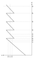
- FIG. 2 is a graph showing an example of positive rotation speed sound data output by a sound data output unit of a saddle-type electric vehicle according to a second embodiment of the present invention.
- FIG. 3 is a graph showing another example of the positive rotation speed sound data output by the sound data output unit of the saddle type electric vehicle according to the second embodiment of the present invention.
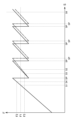
- FIG. 4 is a graph showing an example of positive rotation speed sound data output by a sound data output unit of a saddle-type electric vehicle according to a third embodiment of the present invention.
- FIG. 1 is a diagram illustrating the configuration of a saddle-type electric vehicle according to a first embodiment of the present invention.
- FIG. 2 is a graph showing an example of positive rotation speed sound data output by a sound data output unit of a saddle-type electric vehicle according to a second embodiment of the present invention.
- FIG. 3 is a graph showing another example of the positive
- FIG. 5 is a graph showing an example of positive rotation speed sound data output by a sound data output unit of a saddle-type electric vehicle according to a third embodiment of the present invention.
- FIG. 6 is a schematic diagram of a saddle-type electric vehicle according to a fourth embodiment of the present invention.
- the saddle-type electric vehicle 1 includes an electric motor 2, a driving wheel 3, a saddle-type seat 4 on which a rider R sits in a saddled state, and a sound data output unit 5.
- the driving wheel 3 is driven by the electric motor 2 via a continuously variable transmission (not shown) or a two-speed transmission (not shown), or without a transmission.
- the driving wheel 3 is a rear wheel in FIG. 1, the driving wheel 3 may be a front wheel.
- At least a portion of the saddle-type seat 4 is disposed above the electric motor 2 or the driving wheel 3 in the vehicle up-down direction.
- the positional relationship between the saddle-type seat 4, the electric motor 2, and the driving wheel 3 is not limited to the positional relationship shown in FIG. 1.
- U indicates the vehicle up-down direction
- D indicates the vehicle down-down direction.
- the sound data output unit 5 is configured to acquire information on the rotation speed S, which is the rotation speed of the electric motor 2 or the rotation speed of the drive wheels 3.
- the sound data output unit 5 is configured to generate and output rotation speed sound data DA including data on the main frequency F of the sound corresponding to the rotation speed S of the electric motor 2 or the drive wheels 3, as sound data that is the source of the sound signal sent to the sound generating device 100 configured to generate sound to be heard by the rider R seated on the saddle-type seat 4.
- FIG. 1 an example of the sound generating device 100 installed on the saddle-type electric vehicle 1 is shown by a dashed line, and an example of the sound generating device 100 not installed on the saddle-type electric vehicle 1 is shown by a two-dot chain line.
- FIG. 1 includes a graph showing an example of the relationship between the main frequency F of the sound in the rotation speed sound data DA and the rotation speed S of the electric motor 2 or the drive wheels 3.
- the region of the rotation speed S which is the horizontal axis of the graph in FIG. 1, may be the entire region of the rotation speed S of the electric motor 2 or the drive wheels 3 when the drive wheels 3 are driven by the electric motor 2 via a continuously variable transmission or two-speed transmission, or without a transmission, or may be a part of the entire region.
- the main frequency F of the sound in the rotational speed sound data DA corresponding to the first rotational speed S1 of the electric motor 2 or the drive wheels 3 arranged below at least a portion of the saddle-type seat 4 in the vehicle vertical direction is defined as the first frequency F1.
- the sound data output unit 5 is configured to output rotational speed sound data DA in which the first frequency F1 is the main frequency F of the sound at a second rotational speed S2 that is higher than the first rotational speed S1, and to output rotational speed sound data DA in which the main frequency F of the sound is a frequency different from the first frequency F1 at a third rotational speed S3 that is higher than the first rotational speed S1 and lower than the second rotational speed S2.
- the sound data output unit 5 outputs the rotation speed sound data DA having the first frequency F1 as the main frequency F of the sound
- the sound data output unit 5 outputs the rotation speed sound data DA having a frequency different from the first frequency F1 as the main frequency F of the sound.
- the graph in FIG. 1 shows the third rotation speed S3a and the third rotation speed S3b as two examples of the third rotation speed S3, the third rotation speed S3 in the rotation speed sound data DA in FIG. 1 is not limited to these.
- a saddle-type electric vehicle 1 having a drive wheel 3 driven by an electric motor 2 via a continuously variable transmission or a two-speed transmission or without a transmission it is possible to provide the rider R with sound information that is more easily recognized.
- the rate of change of the main frequency F of the sound with respect to the change in the rotation speed S of the electric motor 2 or the drive wheel 3 can be made larger.
- the rider R compared to a case where the main frequency F of the sound is always increased with an increase in the rotation speed S of the electric motor 2 or the drive wheel 3, it is easier for the rider R to create a running rhythm for the saddle-type electric vehicle 1.
- the rider R grasp the state of the saddle-type electric vehicle 1, such as the vehicle speed, from the sound generated by the sound generating device 100 according to the rotation speed sound data DA.
- FIG. 2 is a graph showing an example of the relationship between the main frequency F of the sound in the rotation speed sound data DA and the rotation speed S of the electric motor 2 or the drive wheels 3 in the second embodiment.
- Fig. 3 is a graph showing another example of the relationship between the main frequency F of the sound in the rotation speed sound data DA and the rotation speed S of the electric motor 2 or the drive wheels 3 in the second embodiment.
- the region of the rotation speed S which is the horizontal axis of the graphs in Figs.
- the sound data output unit 5 of the second embodiment is configured to output rotation speed sound data DA having a second frequency F2 higher than the first frequency F1 as the main frequency F of the sound at a fourth rotation speed S4 that is higher than the first rotation speed S1 and lower than the second rotation speed S2, and to output rotation speed sound data DA having a third frequency F3 lower than the first frequency F1 as the main frequency F of the sound at a fifth rotation speed S5 that is higher than the fourth rotation speed S4 and lower than the second rotation speed S2.
- Both the fourth rotation speed S4 and the fifth rotation speed S5 correspond to the third rotation speed S3 in the first embodiment.
- the rotation speed S at which the rate of change of the main frequency F of the sound in the rotation speed sound data DA with respect to the change in the rotation speed S of the electric motor 2 or the drive wheel 3 changes from positive to negative is defined as the change point SP.
- the sound data output unit 5 of the second embodiment may be configured to generate and output rotational speed sound data DA such that the rotational speed S of the electric motor 2 or the drive wheels 3 passes through multiple change points SP as it increases from the first rotational speed S1 to a sixth rotational speed S6 that is higher than the second rotational speed S2.
- the rotational speed of the electric motor 2 and the rotational speed of the drive wheels 3 may correspond one-to-one. Note that, although there are four change points SP between the first rotational speed S1 and the sixth rotational speed S6 in FIG. 3, the number of change points SP is not limited to this.
- the change in the main frequency F of the sound in the rotational speed sound data DA in response to a change in the rotational speed S of the electric motor 2 or the drive wheels 3 is not limited to that shown in Figures 2 and 3.
- the rotational speed at which the rate of change of the main frequency F of the sound in the rotational speed sound data DA in response to an increase in the rotational speed S of the electric motor 2 or the drive wheels 3 changes from positive to negative is the same as the rotational speed at which the rate of change of the main frequency F of the sound in the rotational speed sound data DA in response to a decrease in the rotational speed S of the electric motor 2 or the drive wheels 3 changes from positive to negative, but may be different.
- the change in frequency of the sound generated in response to changes in vehicle speed is similar to the change in frequency of the sound obtained from a saddle-type vehicle having an engine and a multi-speed transmission in response to changes in vehicle speed.
- the main frequency F of the sound in the rotational speed sound data DA is changed in this way, it is easier for the rider R to create a driving rhythm for the saddle-type electric vehicle 1.
- the rider R grasps the state of the saddle-type electric vehicle 1, such as the vehicle speed, from the sound generated by the sound generating device 100 in response to the rotational speed sound data DA.
- FIG. 4 is a graph showing an example of the relationship between the main frequency F of the sound in the rotation speed sound data DA and the rotation speed S of the electric motor 2 or the drive wheels 3 in the third embodiment.
- Fig. 5 is a graph showing another example of the relationship between the main frequency F of the sound in the rotation speed sound data DA and the rotation speed S of the electric motor 2 or the drive wheels 3 in the third embodiment. The region of the rotation speed S on the horizontal axis of the graphs in Figs.
- 4 and 5 may be the entire region of the rotation speed S of the electric motor 2 or the drive wheels 3 when the drive wheels 3 are driven by the electric motor 2 via a continuously variable transmission or a two-speed transmission or without a transmission, or may be a part of the entire region.
- the sound data output unit 5 of the third embodiment is configured to be able to change the change point SP.
- the definition of the change point SP is as described in the second embodiment.
- the relationship between the main frequency F and the rotation speed S in the rotation speed sound data DA before the change point SP is changed is shown by a solid line
- the relationship between the main frequency F and the rotation speed S in the rotation speed sound data DA when the change point SP is increased is shown by a two-dot chain line.
- the change amount of the change point SP is small, but the change amount of the change point SP may be large.
- all of the multiple change points SP are changed, but only some of the multiple change points SP may be changed.
- the change amount of the multiple change points SP is almost the same, but the change amount of the multiple change points SP may be different.
- the change in the main frequency F of the sound in the rotation speed sound data DA with respect to the change in the rotation speed S of the electric motor 2 or the drive wheels 3 is not limited to that shown in FIG. 4 and FIG. 5.
- the rotation speed at which the rate of change of the main frequency F of the sound in the rotation speed sound data DA changes from positive to negative in response to an increase in the rotation speed S of the electric motor 2 or the drive wheels 3 is the same as the rotation speed at which the rate of change of the main frequency F of the sound in the rotation speed sound data DA changes from positive to negative in response to a decrease in the rotation speed S of the electric motor 2 or the drive wheels 3, but may be different.
- the change point SP may be changed, for example, in response to differences in the environment, such as the route on which the saddle riding type electric vehicle 1 travels. More specifically, for example, the change point SP may be changed in response to the shape of the route. Also, the change point SP may be changed, for example, in response to differences in the rider R riding the saddle riding type electric vehicle 1. More specifically, for example, the change point SP may be changed in response to the driving technique of the rider R. Also, the change point SP may be changed in response to differences in the saddle riding type electric vehicle 1. The change point SP may be changed by combining these examples. Also, for example, in a race to compete for the longest driving time, the change point SP may be adjusted to shorten the driving time. If the change point SP is slightly increased, it may be possible to slightly slow down the vehicle speed that the rider R feels from the sound generated by the sound generating device 100. As a result, it may be possible to shorten the driving time.
- the fourth embodiment has the configuration of the first embodiment.
- the fourth embodiment may have the configuration of the second or third embodiment.
- the sound data output unit 5 according to the fourth embodiment is configured to generate and output notification sound data DB different from the rotation speed sound data DA including data on the main frequency F of the sound according to the rotation speed S of the electric motor 2 or the driving wheel 3 as sound data that is the source of the sound signal sent to the sound generating device 100.
- the sound generated by the sound generating device 100 according to the notification sound data DB can notify the rider R of various information depending on the timing and type of the sound. Therefore, according to the saddle-type electric vehicle 1 according to the present embodiment, sound information that is more easily recognized and can notify the rider R of more information can be provided to the rider R.
- the sound data output unit 5 may be configured to output the alarm sound data DB when outputting the rotation speed sound data DA.
- the sound generating device 100 may generate sound based on both a sound signal C based on the rotation speed sound data DA and a sound signal C based on the alarm sound data DB. As shown in FIG. 6(b), the sound generating device 100 may generate sound based on a sound signal C based on both the rotation speed sound data DA and the alarm sound data DB.
- the sound data output unit 5 may be configured to output the alarm sound data DB when the rotation speed sound data DA is not being output.
- the sound data output unit 5 may be configured to output the alarm sound data DB both when the rotation speed sound data DA is not being output and when the rotation speed sound data DA is not being output.
- the notification sound data DB may be data for generating a sound to notify the rider R of at least one of the state of the saddle riding type electric vehicle 1 and the state around the saddle riding type electric vehicle 1. Specific examples of the notification sound data DB are described below. However, the notification sound data DB of this embodiment is not limited to these.
- the saddle-type electric vehicle 1 may be equipped with a position information acquisition device (not shown) that acquires position information of the saddle-type electric vehicle 1.
- the sound data output unit 5 may generate and output notification sound data DB according to the position information of the saddle-type electric vehicle 1 acquired by the position information acquisition device.
- the notification sound data DB may be output to notify the rider R that the saddle-type electric vehicle 1 has reached a predetermined position. More specifically, for example, the notification sound data DB may be output when the distance to a corner ahead in the path has reached a predetermined distance. This makes it possible to inform the rider R of the timing to start decelerating, for example.
- the sound data output unit 5 may generate and output the notification sound data DB according to the position information of the saddle-type electric vehicle 1 acquired by the position information acquisition device and the rotation speed S of the electric motor 2 or the drive wheels 3.
- the notification sound data DB may be output to notify the rider R that the rotation speed S of the electric motor 2 or the drive wheels 3 when the saddle-type electric vehicle 1 reaches a predetermined position is lower or higher than a predetermined speed. More specifically, for example, the notification sound data DB may be output when the vehicle speed when the distance to a corner ahead in the path reaches a predetermined distance is higher than the predetermined speed.
- the notification sound data DB may be output when the vehicle speed when the predetermined position is reached is lower than the predetermined speed. This makes it possible to urge the rider R to accelerate at a timing appropriate for acceleration, for example.
- the sound data output unit 5 may generate and output the alarm sound data DB according to the rotation speed S of the electric motor 2 or the drive wheels 3.
- the alarm sound data DB may be output to notify the rider R that the rotation speed S of the electric motor 2 or the drive wheels 3 has reached a predetermined speed. More specifically, for example, the alarm sound data DB may be output when the vehicle speed is higher than a predetermined speed. This can, for example, prompt the rider R to decelerate. Also, for example, the alarm sound data DB may be output when the vehicle speed is lower than a predetermined speed. This can, for example, prompt the rider R to accelerate.
- 1 saddle-type electric vehicle
- 2 electric motor
- 3 drive wheel
- 4 saddle-type seat
- 5 sound data output unit
- 100 sound generating device
- DA rotational speed sound data
- DB notification sound data
- F main frequency
- F1 first frequency
- F2 second frequency
- F3 third frequency
- R rider
- S rotational speed of electric motor or drive wheel
- S1 first rotational speed
- S2 second rotational speed
- S3, S3a, S3b third rotational speed
- S4 fourth rotational speed
- S5 fifth rotational speed
- SP change point
Landscapes
- Engineering & Computer Science (AREA)
- Mechanical Engineering (AREA)
- Chemical & Material Sciences (AREA)
- Combustion & Propulsion (AREA)
- Transportation (AREA)
- Physics & Mathematics (AREA)
- Acoustics & Sound (AREA)
- Electric Propulsion And Braking For Vehicles (AREA)
Abstract
鞍乗型電動車両(1)が有する音データ出力部(5)は、音発生装置(100)に送られる音信号の元となる音データとして、電動モータ(2)または駆動輪(3)の回転速度(S)に応じた音のメイン周波数(F)に関するデータを含む回転速度音データ(DA)を生成して出力する。ライダー(R)が着座する鞍乗型シート(4)の少なくとも一部よりも車両上下方向の下方向に配置された電動モータまたは駆動輪の第1回転速度(S1)に応じた回転速度音データにおける音のメイン周波数を第1周波数(F1)と定義すると、音データ出力部は、第1回転速度よりも高い第2回転速度(S2)において、第1周波数を音のメイン周波数とする回転速度音データを出力し、且つ、第1回転速度よりも高く第2回転速度よりも低い第3回転速度(S3)において、第1周波数とは異なる周波数を音のメイン周波数とする回転速度音データを出力する。
Description
本発明は、無段変速機もしくは二段変速機を介してまたは変速機を介さずに電動モータによって駆動される駆動輪を有する鞍乗型電動車両に関する。
従来、電動二輪車(electric motorcycle)などの鞍乗型電動車両が知られている。例えば特許文献1では、ライダーに認知されやすい音情報をライダーに提供する電動二輪車が提案されている。特許文献1に記載の電動二輪車は、音を発生させる音発生ユニットと、電動モータの回転速度に応じた周波数の音を発生させるように音発生ユニットを制御する音制御ユニットとを有する。音制御ユニットは、電動モータの回転速度が低い低速領域における電動モータの回転速度の変化に対する音の周波数の変化率が、低速領域よりも電動モータの回転速度が高い中高速領域における電動モータの回転速度の変化に対する音の周波数の変化率よりも大きくなるように、音発生ユニットを制御する。
自動二輪車(motorcycle)などの鞍乗型車両は、一般的に、自動車(四輪車)よりも軽量且つコンパクトで、自動車よりも機動性が高い傾向にある。また、自動二輪車などの鞍乗型車両のライダーは、一般的に、メーターによる車両速度などの確認に加え、車両から得られる振動および音などの情報の変化と車両の周囲の景色の変化から、車両の状態(例えば車両速度)を把握する傾向が高い。そのため、自動二輪車などの鞍乗型車両において、車両から得られる情報は、自動車に比べてより認知されやすいことが求められる。
電動モータによって駆動される鞍乗型電動車両において、車両から得られる振動および音は、エンジンによって駆動される鞍乗型車両に比べて小さくなるため、車両から得られる情報が認知されにくくなる傾向がある。
また、例えば車両から得られる音情報に関して、鞍乗型電動車両、特に、駆動輪が無段変速機もしくは二段変速機を介してまたは変速機を介さずに電動モータによって駆動される鞍乗型電動車両においては、電動モータの回転速度の変化に対する音の周波数の変化率が小さくなる傾向がある。
特許文献1では、電動二輪車において、低速領域における電動モータの回転速度の変化に対する音の周波数の変化率を大きくする技術が提案されている。このように、無段変速機もしくは二段変速機を介してまたは変速機を介さずに電動モータによって駆動される駆動輪を有する鞍乗型電動車両において、より認知されやすい音情報をライダーに提供することが求められている。
電動モータによって駆動される鞍乗型電動車両において、車両から得られる振動および音は、エンジンによって駆動される鞍乗型車両に比べて小さくなるため、車両から得られる情報が認知されにくくなる傾向がある。
また、例えば車両から得られる音情報に関して、鞍乗型電動車両、特に、駆動輪が無段変速機もしくは二段変速機を介してまたは変速機を介さずに電動モータによって駆動される鞍乗型電動車両においては、電動モータの回転速度の変化に対する音の周波数の変化率が小さくなる傾向がある。
特許文献1では、電動二輪車において、低速領域における電動モータの回転速度の変化に対する音の周波数の変化率を大きくする技術が提案されている。このように、無段変速機もしくは二段変速機を介してまたは変速機を介さずに電動モータによって駆動される駆動輪を有する鞍乗型電動車両において、より認知されやすい音情報をライダーに提供することが求められている。
本発明は、無段変速機もしくは二段変速機を介してまたは変速機を介さずに電動モータによって駆動される駆動輪を有する鞍乗型電動車両において、より認知されやすい音情報をライダーに提供できることを目的とする。
本願発明者らは、特許文献1の技術を検討した。特許文献1の技術では、低速領域における電動モータの回転速度の変化に対する音の周波数の変化率が大きいものの、中高速域における電動モータの回転速度の変化に対する音の周波数の変化率は低速領域に比べて小さい。
そこで、本願発明者らは、より広い回転速度領域において音情報の周波数の変化率を大きくするために、従来とは異なる回転速度に対する依存性によって音情報の周波数を変化させることを検討した。
その結果、異なる車両速度において同じ周波数の音が出現しても、異なる車両速度であることをライダーは認識できるという新たな知見を見出した。本願発明者らは、上記知見を利用して、本願発明に思い至った。
そこで、本願発明者らは、より広い回転速度領域において音情報の周波数の変化率を大きくするために、従来とは異なる回転速度に対する依存性によって音情報の周波数を変化させることを検討した。
その結果、異なる車両速度において同じ周波数の音が出現しても、異なる車両速度であることをライダーは認識できるという新たな知見を見出した。本願発明者らは、上記知見を利用して、本願発明に思い至った。
本発明の一実施形態の鞍乗型電動車両は、以下の構成を有する。
電動モータと、無段変速機もしくは二段変速機を介してまたは変速機を介さずに前記電動モータによって駆動される駆動輪と、前記電動モータまたは前記駆動輪よりも車両上下方向の上方向に少なくとも一部が配置され、ライダーが鞍乗状態で着座する鞍乗型シートと、前記電動モータまたは前記駆動輪の回転速度に関する情報を取得し、前記鞍乗型シートに着座した前記ライダーに聞かせるための音を発生させるように構成される音発生装置に送られる音信号の元となる音データとして、前記電動モータまたは前記駆動輪の回転速度に応じた前記音のメイン周波数に関するデータを含む回転速度音データを生成して出力する音データ出力部と、を備えた鞍乗型電動車両であって、前記音データ出力部は、前記鞍乗型シートの少なくとも一部よりも車両上下方向の下方向に配置された前記電動モータまたは前記駆動輪の第1回転速度に応じた前記回転速度音データにおける前記音の前記メイン周波数を第1周波数と定義した場合、前記第1回転速度よりも高い第2回転速度において、前記第1周波数を前記音の前記メイン周波数とする前記回転速度音データを出力し、且つ、前記第1回転速度よりも高く前記第2回転速度よりも低い第3回転速度において、前記第1周波数とは異なる周波数を前記音の前記メイン周波数とする前記回転速度音データを出力するように構成される。
電動モータと、無段変速機もしくは二段変速機を介してまたは変速機を介さずに前記電動モータによって駆動される駆動輪と、前記電動モータまたは前記駆動輪よりも車両上下方向の上方向に少なくとも一部が配置され、ライダーが鞍乗状態で着座する鞍乗型シートと、前記電動モータまたは前記駆動輪の回転速度に関する情報を取得し、前記鞍乗型シートに着座した前記ライダーに聞かせるための音を発生させるように構成される音発生装置に送られる音信号の元となる音データとして、前記電動モータまたは前記駆動輪の回転速度に応じた前記音のメイン周波数に関するデータを含む回転速度音データを生成して出力する音データ出力部と、を備えた鞍乗型電動車両であって、前記音データ出力部は、前記鞍乗型シートの少なくとも一部よりも車両上下方向の下方向に配置された前記電動モータまたは前記駆動輪の第1回転速度に応じた前記回転速度音データにおける前記音の前記メイン周波数を第1周波数と定義した場合、前記第1回転速度よりも高い第2回転速度において、前記第1周波数を前記音の前記メイン周波数とする前記回転速度音データを出力し、且つ、前記第1回転速度よりも高く前記第2回転速度よりも低い第3回転速度において、前記第1周波数とは異なる周波数を前記音の前記メイン周波数とする前記回転速度音データを出力するように構成される。
この構成によると、音データ出力部は、ライダーに聞かせる音を発生させる音発生装置に送られる音信号の元となる音データとして、回転速度音データを生成して出力する。回転速度音データは、鞍乗型シートの少なくとも一部よりも車両上下方向の下方向に配置された電動モータまたは駆動輪の回転速度に応じた音のメイン周波数に関するデータを含む。音発生装置は、音データ出力部から出力された回転速度音データに基づいた音信号に基づいて音を発生させる。したがって、音発生装置は、鞍乗型シートの少なくとも一部よりも車両上下方向の下方向に配置された電動モータまたは駆動輪の回転速度に応じたメイン周波数の音を発生させる。電動モータまたは駆動輪の第1回転速度に応じた回転速度音データにおける音のメイン周波数を第1周波数と定義した場合、音データ出力部は、第1回転速度よりも高い第2回転速度において、第1周波数を音のメイン周波数とする回転速度音データを出力する。さらに、音データ出力部は、第1回転速度よりも高く第2回転速度よりも低い第3回転速度において、第1周波数とは異なる周波数を音のメイン周波数とする回転速度音データを出力する。そのため、電動モータまたは駆動輪の回転速度の増加に対して必ず音のメイン周波数を増加させる場合に比べて、電動モータまたは駆動輪の回転速度のより広い領域において、音のメイン周波数の領域を拡大することなく、電動モータまたは駆動輪の回転速度の変化に対する音のメイン周波数の変化率をより大きくすることができる。しかも、音発生装置が発生させる音は、鞍乗型シートの少なくとも一部よりも車両上下方向の下方向に配置された電動モータまたは駆動輪の回転速度に応じたメイン周波数の音である。そのため、ライダーは音発生装置が回転速度音データに応じて発生させる音を認知しやすい。
以上により、無段変速機もしくは二段変速機を介してまたは変速機を介さずに電動モータによって駆動される駆動輪を有する鞍乗型電動車両において、より認知されやすい音情報をライダーに提供することができる。
以上により、無段変速機もしくは二段変速機を介してまたは変速機を介さずに電動モータによって駆動される駆動輪を有する鞍乗型電動車両において、より認知されやすい音情報をライダーに提供することができる。
本発明の一実施形態の鞍乗型電動車両は、以下の構成を有してもよい。
前記音データ出力部は、前記第1回転速度よりも高く且つ前記第2回転速度よりも低い第4回転速度において、前記第1周波数よりも高い第2周波数を前記音の前記メイン周波数とする前記回転速度音データを出力し、且つ、前記第4回転速度よりも高く且つ前記第2回転速度よりも低い第5回転速度において、前記第1周波数よりも低い第3周波数を前記音の前記メイン周波数とする前記回転速度音データを出力するように構成される。
前記音データ出力部は、前記第1回転速度よりも高く且つ前記第2回転速度よりも低い第4回転速度において、前記第1周波数よりも高い第2周波数を前記音の前記メイン周波数とする前記回転速度音データを出力し、且つ、前記第4回転速度よりも高く且つ前記第2回転速度よりも低い第5回転速度において、前記第1周波数よりも低い第3周波数を前記音の前記メイン周波数とする前記回転速度音データを出力するように構成される。
この構成によると、無段変速機もしくは二段変速機を介してまたは変速機を介さずに電動モータによって駆動される駆動輪を有する鞍乗型電動車両において、より認知されやすい音情報をライダーに提供することができる。
本発明の一実施形態の鞍乗型電動車両は、以下の構成を有してもよい。
前記電動モータまたは前記駆動輪の回転速度の変化に対する前記回転速度音データにおける前記音の前記メイン周波数の変化率が正から負に変化する前記回転速度を、変化点と定義した場合、前記音データ出力部は、前記変化点を変更可能に構成される。
前記電動モータまたは前記駆動輪の回転速度の変化に対する前記回転速度音データにおける前記音の前記メイン周波数の変化率が正から負に変化する前記回転速度を、変化点と定義した場合、前記音データ出力部は、前記変化点を変更可能に構成される。
この構成によると、電動モータまたは駆動輪の回転速度の変化に対する回転速度音データにおける音のメイン周波数の変化率が正から負に変化する回転速度(変化点)は、変更することができる。例えば、鞍乗型電動車両が走行する経路などの環境の違い、鞍乗型電動車両に乗車するライダーの違い、または、鞍乗型電動車両の違いなどに応じて、変化点(回転速度)を変更することができる。変化点において音発生装置から発生する音は、特に認知されやすい。そのため、変化点(回転速度)を変更することで、より認知されやすい音情報をより活用しやすいようにライダーに提供することができる。
本発明の一実施形態の鞍乗型電動車両は、以下の構成を有してもよい。
前記音データ出力部は、前記音発生装置に送られる前記音信号の元となる前記音データとして、前記電動モータまたは前記駆動輪の回転速度に応じた前記音のメイン周波数に関するデータを含む前記回転速度音データとは異なる報知音データを生成して出力するように構成される。
前記音データ出力部は、前記音発生装置に送られる前記音信号の元となる前記音データとして、前記電動モータまたは前記駆動輪の回転速度に応じた前記音のメイン周波数に関するデータを含む前記回転速度音データとは異なる報知音データを生成して出力するように構成される。
この構成によると、音データ出力部が報知音データを出力すると、音発生装置は報知音データに基づいた音信号に基づいて音を発生させる。つまり、音発生装置は、報知音データに応じた音を発生させる。報知音データは回転速度音データとは異なる。したがって、音発生装置が報知音データに応じて発生させる音は、音発生装置が回転速度音データに応じて発生させる音とは異なる。そのため、音発生装置が、報知音データに応じた音と回転速度音データに応じた音の両方を発生させていても、ライダーはこの2つの音を認知しやすい。また、音発生装置が報知音データに応じて発生させる音は、音の発生タイミングと音の種類によって、ライダーに様々な情報を報知することができる。したがって、無段変速機もしくは二段変速機を介してまたは変速機を介さずに電動モータによって駆動される駆動輪を有する鞍乗型電動車両において、より認知されやすく且つより多くの情報をライダーに報知することができる音情報をライダーに提供することができる。
本発明の一実施形態の鞍乗型電動車両は、以下の構成を有してもよい。
前記鞍乗型電動車両の位置情報を取得する位置情報取得装置を更に備え、前記音データ出力部は、前記位置情報取得装置により取得された前記鞍乗型電動車両の前記位置情報に応じた前記報知音データを生成して出力するように構成される。
前記鞍乗型電動車両の位置情報を取得する位置情報取得装置を更に備え、前記音データ出力部は、前記位置情報取得装置により取得された前記鞍乗型電動車両の前記位置情報に応じた前記報知音データを生成して出力するように構成される。
この構成によると、音データ出力部は、鞍乗型電動車両の位置情報に応じた報知音データを出力する。そのため、音発生装置がこの報知音データに応じて発生させる音は、音の発生タイミングと音の種類によって、鞍乗型電動車両の位置情報に関連する情報をライダーに知らせることができる。例えば、鞍乗型電動車両が所定の位置に達したことをライダーに報知するために報知音データを出力してもよい。このように、無段変速機もしくは二段変速機を介してまたは変速機を介さずに電動モータによって駆動される駆動輪を有する鞍乗型電動車両において、より認知されやすく且つ鞍乗型電動車両の位置情報に関連する情報をライダーに報知することができる音情報を、ライダーに提供することができる。
本発明の一実施形態の鞍乗型電動車両は、以下の構成を有してもよい。
前記音データ出力部は、前記位置情報取得装置により取得された前記鞍乗型電動車両の前記位置情報、および、前記電動モータまたは前記駆動輪の回転速度に応じた前記報知音データを生成して出力するように構成される。
前記音データ出力部は、前記位置情報取得装置により取得された前記鞍乗型電動車両の前記位置情報、および、前記電動モータまたは前記駆動輪の回転速度に応じた前記報知音データを生成して出力するように構成される。
この構成によると、音データ出力部は、鞍乗型電動車両の位置情報および電動モータまたは駆動輪の回転速度に応じた報知音データを出力する。そのため、音発生装置がこの報知音データに応じて発生させる音は、音の発生タイミングと音の種類によって、鞍乗型電動車両の位置情報と電動モータまたは駆動輪の回転速度の両方に関連する情報をライダーに報知することができる。例えば、鞍乗型電動車両が所定の位置に達した時の電動モータまたは駆動輪の回転速度が所定の速度よりも低いまたは高いことをライダーに報知するために報知音データを出力してもよい。このように、無段変速機もしくは二段変速機を介してまたは変速機を介さずに電動モータによって駆動される駆動輪を有する鞍乗型電動車両において、より認知されやすく且つ鞍乗型電動車両の位置情報と電動モータまたは駆動輪の回転速度の両方に関連する情報をライダーに報知することができる音情報を、ライダーに提供することができる。
本発明の一実施形態の鞍乗型電動車両は、以下の構成を有してもよい。
前記音データ出力部は、前記電動モータまたは前記駆動輪の回転速度に応じた前記報知音データを生成して出力するように構成される。
前記音データ出力部は、前記電動モータまたは前記駆動輪の回転速度に応じた前記報知音データを生成して出力するように構成される。
この構成によると、音データ出力部は、電動モータまたは駆動輪の回転速度に応じた報知音データを出力する。そのため、音発生装置がこの報知音データに応じて発生させる音は、音の発生タイミングと音の種類によって、電動モータまたは駆動輪の回転速度に関連する情報をライダーに報知することができる。例えば、電動モータまたは駆動輪の回転速度が所定の速度に達したことをライダーに報知するために報知音データを出力してもよい。このように、無段変速機もしくは二段変速機を介してまたは変速機を介さずに電動モータによって駆動される駆動輪を有する鞍乗型電動車両において、より認知されやすく且つ電動モータまたは駆動輪の回転速度に関連する情報をライダーに報知することができる音情報を、ライダーに提供することができる。
本発明および実施形態において、鞍乗型電動車両とは、電動モータにより駆動される駆動輪を有する鞍乗型車両である。鞍乗型電動車両は、ライダー(運転者)が鞍乗状態で乗車する車両である。鞍乗型電動車両は、例えば、自動二輪車、自動三輪車(motor tricycle)、四輪バギー(ATV:All Terrain Vehicle / 全地形型車両)、スノーモービルなどである。本発明および実施形態において、電動モータにより駆動される駆動輪は、後輪でもよく、前輪でもよい。鞍乗型電動車両は、前輪と後輪の両方が電動モータによって駆動されてもよい。鞍乗型電動車両は、電動モータによって駆動されない従動輪を有してもよい。本発明および実施形態において、鞍乗型電動車両は、電動モータに電力を供給するバッテリを有する。本発明および実施形態において、鞍乗型電動車両は、エンジンを有さなくてもよく、有してもよい。鞍乗型電動車両がエンジンを有する場合、鞍乗型電動車両は、エンジンが駆動していない時に電動モータによって駆動輪を駆動できるように構成され、且つ、音データ出力部は、エンジンが駆動していない時の電動モータまたは駆動輪の回転速度に応じた回転速度音データを生成して出力するように構成される。鞍乗型電動車両がエンジンを有する場合、多段変速機を介してエンジンの駆動力が後輪または前輪に伝達されてもよい。
本発明および実施形態において、無段変速機もしくは二段変速機を介してまたは変速機を介さずに電動モータによって駆動される駆動輪とは、電動モータから無段変速機もしくは二段変速機を介して伝達される電動モータの駆動力によって駆動される、または、電動モータから変速機を介さずに伝達される電動モータの駆動力によって駆動される駆動輪を意味する。
本発明および実施形態において、駆動輪は、駆動輪の回転速度の広い領域において、電動モータの回転速度と駆動輪の回転速度とが一対一で対応付けられるように、無段変速機もしくは二段変速機を介してまたは変速機を介さずに電動モータによって駆動されてもよい。駆動輪の回転速度の広い領域は、例えば、駆動輪が、無段変速機もしくは二段変速機を介してまたは変速機を介さずに電動モータによって駆動される場合における駆動輪の回転速度の全域のうちの半分またはそれより広い領域でもよい。
本発明および実施形態において、駆動輪が変速機を介さずに電動モータによって駆動されるとは、駆動輪が無段変速機および2段以上の変速段を有する多段変速機のどちらも介さずに電動モータによって駆動されることを意味する。変速機には減速機は含まれない。
本発明および実施形態において、駆動輪は、駆動輪の回転速度の広い領域において、電動モータの回転速度と駆動輪の回転速度とが一対一で対応付けられるように、無段変速機もしくは二段変速機を介してまたは変速機を介さずに電動モータによって駆動されてもよい。駆動輪の回転速度の広い領域は、例えば、駆動輪が、無段変速機もしくは二段変速機を介してまたは変速機を介さずに電動モータによって駆動される場合における駆動輪の回転速度の全域のうちの半分またはそれより広い領域でもよい。
本発明および実施形態において、駆動輪が変速機を介さずに電動モータによって駆動されるとは、駆動輪が無段変速機および2段以上の変速段を有する多段変速機のどちらも介さずに電動モータによって駆動されることを意味する。変速機には減速機は含まれない。
本発明および実施形態において、鞍乗型シートとは、ライダーが座る部位であって、ライダーの腰または背中がもたれかかる部位は含まない。ライダーは鞍乗型シートに鞍乗状態で着座する。ライダーが鞍乗状態で着座するとは、ライダーが鞍にまたがるような状態で着座することを意味する。本発明および実施形態において、電動モータまたは駆動輪よりも車両上下方向の上方向に少なくとも一部が配置される鞍乗型シートは、電動モータと駆動輪の両方よりも車両上下方向の上方向に少なくとも一部が配置される鞍乗型シートを除外しない。つまり、本発明および実施形態において、鞍乗型シートの少なくとも一部は、電動モータおよび駆動輪の少なくとも一方よりも車両上下方向の上方向に配置される。
本発明および実施形態において、音発生装置は、受信した音信号に基づいて音を発生させるように構成される。音発生装置は、受信した音信号を音に変換するように構成される。音発生装置の構成および配置位置は、鞍乗型シートに着座したライダーに音を聞かせることができる構成および配置位置であれば、特に限定されない。音発生装置は、鞍乗型電動車両に設置されてもよく、ライダーに装着されてもよい。ライダーに装着される音発生装置は、例えば、ライダーに装着されるヘッドホンまたはイヤホンでもよい。ヘッドホンまたはイヤホンは、空気伝導式でもよく、骨伝導式でもよい。ライダーに装着される音発生装置は、例えば、ライダーが装着するヘルメットに設置された空気伝導式または骨伝導式のスピーカーでもよい。鞍乗型電動車両に設置される音発生装置は、空気伝導式のスピーカーである。鞍乗型電動車両に設置される音発生装置は、例えば、鞍乗型シートよりも車両前後方向の前方向に配置されてもよく、鞍乗型シートよりも車両前後方向の後方向に配置されてもよく、車両上下方向における鞍乗型シートの真下に配置されてもよく、鞍乗型シートの内部に配置されてもよい。鞍乗型電動車両に設置される音発生装置は、例えば、鞍乗型シートよりも車両前後方向の前方向に少なくとも一部が配置されてバッテリを収容するバッテリボックスの前部または上部に設置されてもよい。鞍乗型電動車両に設置される音発生装置は、上記以外の位置に配置されたバッテリボックスに設置されてもよい。
本発明および実施形態において、音発生装置に送られる音信号は、音データに基づいて生成される。音データは、音発生装置が発生させる音に関するデータである。音信号の生成は、音データ出力部が行ってもよく、音データ出力部とは異なる装置が行ってもよい。音信号を生成する音データ出力部とは異なる装置は、鞍乗型電動車両に設置されてもよく、設置されなくてもよい。音発生装置への音信号の送信は、音データ出力部が行ってもよく、音データ出力部とは異なる装置が行ってもよい。音信号を送信する音データ出力部とは異なる装置は、鞍乗型電動車両に設置されてもよく、設置されなくてもよい。
本発明および実施形態において、音データ出力部は、プロセッサおよび記憶装置を有する。プロセッサには、マイクロコントローラ、CPU(Central Processing Unit)、マイクロプロセッサ、マルチプロセッサ、特定用途向け集積回路(ASIC)、プログラム可能な論理回路(PLC)、フィールドプログラマブルゲートアレイ(FPGA)および音データを生成して出力する処理を実行することができる任意の他の回路が含まれる。記憶装置は、データやプログラムの保存または記憶を行うための装置である。記憶装置は、レジスタやキャッシュメモリ等の半導体メモリ、メインメモリ(主記憶装置/RAM)、ストレージ(外部記憶装置/補助記憶装置)等が含まれる。本発明および実施形態において、音データ出力部が音データを生成するとは、記憶装置に予め記憶された音データを読み出すことを含む。本発明および実施形態において、音データ出力部は、電動モータの回転速度などを制御する制御装置でもよい。
本発明および実施形態において、音データ出力部が取得する電動モータまたは駆動輪の回転速度に関する情報は、電動モータまたは駆動輪の回転速度の値そのものに限らない。電動モータまたは駆動輪の回転速度に関する情報は、例えば、電動モータの回転速度を制御する信号、電動モータの回転速度を検出するセンサの出力信号、駆動輪または従動輪の回転速度を検出するセンサの出力信号などを含む。駆動輪の回転速度に関する情報は、駆動輪または従動輪の回転速度から算出された車両速度でもよい。駆動輪の回転速度に関する情報は、電動モータの回転速度の情報と無段変速機または二段変速機の変速比の情報の組み合わせでもよい。なお、従動輪の回転速度は、駆動輪の回転速度に応じて変化し、且つ、電動モータの回転速度に応じて変化する。車両速度は、駆動輪の回転速度に応じて変化し、且つ、電動モータの回転速度に応じて変化する。
本発明および実施形態において、回転速度音データは、電動モータまたは駆動輪の回転速度に応じた音のメイン周波数に関するデータを含む。電動モータまたは駆動輪の回転速度に応じた音のメイン周波数に関するデータとは、音のメイン周波数が電動モータまたは駆動輪の回転速度に基づいて設定されたデータに限らない。電動モータまたは駆動輪の回転速度に応じた音のメイン周波数に関するデータは、音データ出力部が取得する電動モータまたは駆動輪の回転速度に関する情報に基づいた、音のメイン周波数に関するデータである。音データ出力部が取得する電動モータまたは駆動輪の回転速度に関する情報の定義は上述した通りである。音データ出力部は、回転速度音データにおける音のメイン周波数を、車両速度または従動輪の回転速度に基づいて変化させてもよい。電動モータまたは駆動輪の回転速度に応じた音のメイン周波数とは、「電動モータまたは駆動輪の回転速度に応じた音」が複数の周波数の音を含む場合に、複数の周波数のうち音の振幅の最も大きい周波数である。「電動モータまたは駆動輪の回転速度に応じた音」は、1つの周波数の音でもよい。
本発明および実施形態において、回転速度音データに含まれる音のメイン周波数に関するデータは、周波数の値そのもののデータに限らない。メイン周波数に関するデータは、例えば、基準周波数に対する倍率に関するデータでもよい。この場合、基準周波数に倍率を乗じた値がメイン周波数である。
本発明および実施形態において、回転速度音データは、音圧に関するデータを含んでもよく、含まなくてもよい。回転速度音データが音圧に関するデータを含む場合、音圧に関するデータは、電動モータまたは駆動輪の回転速度に応じた音圧に関するデータでもよい。音圧に関するデータは、音の振幅に関するデータでもよい。
本発明および実施形態において、音データ出力部は、現在の電動モータまたは駆動輪の回転速度に応じた回転速度音データを生成して出力するように構成される。音発生装置が回転速度音データに基づく音信号に基づいて発生させる音は、エンジンによって駆動される鞍乗型車両において発生する音に似た音でもよい。
本発明および実施形態において、回転速度音データに含まれる音のメイン周波数に関するデータは、周波数の値そのもののデータに限らない。メイン周波数に関するデータは、例えば、基準周波数に対する倍率に関するデータでもよい。この場合、基準周波数に倍率を乗じた値がメイン周波数である。
本発明および実施形態において、回転速度音データは、音圧に関するデータを含んでもよく、含まなくてもよい。回転速度音データが音圧に関するデータを含む場合、音圧に関するデータは、電動モータまたは駆動輪の回転速度に応じた音圧に関するデータでもよい。音圧に関するデータは、音の振幅に関するデータでもよい。
本発明および実施形態において、音データ出力部は、現在の電動モータまたは駆動輪の回転速度に応じた回転速度音データを生成して出力するように構成される。音発生装置が回転速度音データに基づく音信号に基づいて発生させる音は、エンジンによって駆動される鞍乗型車両において発生する音に似た音でもよい。
本発明および実施形態において、電動モータまたは駆動輪の第1回転速度に応じた回転速度音データとは、電動モータまたは駆動輪の第1回転速度に応じた音のメイン周波数のデータを含む回転速度音データである。 本発明および実施形態において、第1回転速度は、電動モータまたは駆動輪の回転速度である。第1回転速度が電動モータの回転速度である場合、第2回転速度および第3回転速度も電動モータの回転速度である。第1回転速度が駆動輪の回転速度である場合、第2回転速度および第3回転速度も駆動輪の回転速度である。
本発明および実施形態において、第1回転速度、第2回転速度および第3回転速度は、電動モータの回転速度と駆動輪の回転速度とが一対一で対応付けられた領域内の電動モータまたは駆動輪の回転速度でもよい。
本発明および実施形態において、第1回転速度、第2回転速度および第3回転速度は、電動モータの回転速度と駆動輪の回転速度とが一対一で対応付けられた領域内の電動モータまたは駆動輪の回転速度でもよい。
本発明および実施形態において、音データ出力部は、第1回転速度よりも高く且つ第2回転速度よりも低い第4回転速度において、第1周波数よりも高い第2周波数を音のメイン周波数とする回転速度音データを出力し、且つ、第4回転速度よりも高く且つ第2回転速度よりも低い第5回転速度において、第1周波数よりも低い第3周波数を音のメイン周波数とする回転速度音データを出力するように構成されてもよい。第4回転速度と第5回転速度のどちらも、本発明における第3回転速度に相当する。この場合、第1回転速度と第2回転速度の間のある回転速度において、電動モータまたは駆動輪の回転速度の変化に対する回転速度音データにおける音のメイン周波数の変化率が、正から負に変化する。第1回転速度、第2回転速度、第4回転速度および第5回転速度の各々において、電動モータまたは駆動輪の回転速度の変化に対する回転速度音データにおける音のメイン周波数の変化率は正の値でもよい。本明細書において、電動モータまたは駆動輪の回転速度の変化に対する回転速度音データにおける音のメイン周波数の変化率とは、電動モータまたは駆動輪の回転速度の単位変化量に対する回転速度音データにおける音のメイン周波数の変化量の変化率を意味する。電動モータまたは駆動輪の回転速度の変化に対する回転速度音データにおける音のメイン周波数の変化率が正である状態とは、回転速度が増加したときにメイン周波数が増加する状態、または、回転速度が減少したときにメイン周波数が減少する状態である。電動モータまたは駆動輪の回転速度の変化に対する回転速度音データにおける音のメイン周波数の変化率が負である状態とは、回転速度が増加したときにメイン周波数が減少する状態、または、回転速度が減少したときにメイン周波数が増加する状態である。ここで、電動モータまたは駆動輪の回転速度の変化に対する音のメイン周波数の変化率が正から負に変化する回転速度を変化点と定義する。変化点は、電動モータまたは駆動輪の回転速度の増加に対する音のメイン周波数の変化率が正から負に変化する回転速度でもよく、電動モータまたは駆動輪の回転速度の減少に対する音のメイン周波数の変化率が正から負に変化する回転速度でもよい。変化点は、回転速度音データにおける音のメイン周波数を、電動モータまたは駆動輪の回転速度で微分したときの値が正から負に変化する回転速度でもよい。
本発明および実施形態において、音データ出力部が、第1回転速度よりも高く且つ第2回転速度よりも低い第4回転速度において、第1周波数よりも高い第2周波数を音のメイン周波数とする回転速度音データを出力し、且つ、第4回転速度よりも高く且つ第2回転速度よりも低い第5回転速度において、第1周波数よりも低い第3周波数を音のメイン周波数とする回転速度音データを出力するように構成される場合、音データ出力部は、変化点を変更不能に構成されてもよく、変化点を変更可能に構成されてもよい。第1回転速度と第2回転速度の間の変化点(回転速度)を変更した場合、変更後の変化点は、第1回転速度と第2回転速度の間にあってもよく、第1回転速度より低くてもよく、第2回転速度よりも高くてもよい。変化点が変更される場合、変化点におけるメイン周波数は変更されなくてもよい。音データ出力部は、変化点におけるメイン周波数を変更可能に構成されてもよい。変化点が変更される場合に、変化点におけるメイン周波数が変更されてもよい。変化点が変更されることなく、変化点におけるメイン周波数が変更されてもよい。音データ出力部が変化点および変化点におけるメイン周波数の少なくとも一方を変更可能に構成される場合、音データ出力部は例えば以下の3つの例のように構成されてもよい。例えば、音データ出力部は、鞍乗型電動車両の状態および鞍乗型電動車両の周囲の状態の少なくとも一方に応じて自動的に変化点および変化点におけるメイン周波数の少なくとも一方を変更してもよい。また、例えば、鞍乗型電動車両の走行前または鞍乗型電動車両の走行中に鞍乗型電動車両の入力部をユーザー(ライダーを含む)が操作することによって、音データ出力部が変化点および変化点におけるメイン周波数の少なくとも一方を変更してもよい。また、例えば、鞍乗型電動車両と無線で通信する装置からの変更指示を音データ出力部が受けたことにより、音データ出力部が変化点および変化点におけるメイン周波数の少なくとも一方を変更してもよい。なお、変化点および変化点におけるメイン周波数の少なくとも一方を変更可能に構成された音データ出力部の構成はこれらの例に限らない。
本発明および実施形態において、音データ出力部は、音発生装置に送られる音信号の元となる音データとして回転速度音データとは異なる報知音データを生成して出力するように構成されてもよい。報知音データは、回転速度音データとは異なる種類の音を発生させるためのデータである。報知音データは、回転速度音データにおける音のメイン周波数とは異なる周波数の音を発生させるデータでもよい。報知音データは、回転速度音データにおける音のメイン周波数よりも高い周波数の音を発生させるためのデータでもよい。報知音データは、音の周波数に関するデータを含んでもよく、含まなくてもよい。報知音データは、音を発生させることを指示するだけのデータでもよい。本発明および実施形態において、報知音データは、鞍乗型電動車両の状態および鞍乗型電動車両の周囲の状態の少なくとも一方をライダーに報知するための音を発生させるためのデータでもよい。例えば、音データ出力部は、鞍乗型電動車両の状態および鞍乗型電動車両の周囲の状態の少なくとも一方に応じて自動的に報知音データを生成して出力してもよい。また、例えば、鞍乗型電動車両の走行前または鞍乗型電動車両の走行中に鞍乗型電動車両の入力部をユーザー(ライダーを含む)が操作することによって、音データ出力部が報知音データを生成して出力してもよい。また、例えば、鞍乗型電動車両と無線で通信する装置からの変更指示を音データ出力部が受けたことにより、音データ出力部が報知音データを生成して出力してもよい。この場合、音データ出力部は、変更指示を取得すると即時に報知音データを出力してもよい。もしくは、音データ出力部は、事前に取得した変更指示に基づいた所定の条件を満たした時に報知音データを出力してもよい。
本発明および実施形態において、音データ出力部は、鞍乗型電動車両が備える位置情報取得装置により取得された鞍乗型電動車両の位置情報に応じた報知音データを生成して出力するように構成されてもよい。位置情報取得装置は、例えば、GNSS(Global Navigation Satellite System / 全球測位衛星システム)受信機でもよい。GNSS受信機は、GNSS衛星からの電波を受信する装置である。位置情報取得装置は、例えば、鞍乗型電動車両に設置されていないGNSS受信機を用いて生成された位置情報を、鞍乗型電動車両の外部から無線通信によって取得する装置でもよい。音データ出力部は、位置情報取得装置により取得された鞍乗型電動車両の位置情報、および、電動モータまたは駆動輪の回転速度に応じた報知音データを生成して出力するように構成されてもよい。音データ出力部は、電動モータまたは駆動輪の回転速度に応じた報知音データを生成して出力するように構成されてもよい。本発明および実施形態において、音データ出力部は、鞍乗型電動車両の位置情報に応じた報知音データ、鞍乗型電動車両の位置情報および電動モータまたは駆動輪の回転速度に応じた報知音データ、および、電動モータまたは駆動輪の回転速度に応じた報知音データのいずれも生成して出力できるように構成されてもよい。
本明細書において、AがBよりも車両上下方向の上方向に配置されるとは、以下の状態を指す。Aは、Bの最上端を通り車両上下方向に直交する平面よりも上方向に配置される。本明細書において、AがBよりも車両上下方向の下方向に配置されるとは、以下の状態を指す。Aは、Bの最下端を通り車両上下方向に直交する平面よりも下方向に配置される。この場合、AとBは、車両上下方向に沿って並んでいてもよく、並んでいなくてもよい。
本明細書において、AがBよりも車両前後方向の前方向に配置されるとは、以下の状態を指す。Aは、Bの最前端を通り車両前後方向に直交する平面よりも前方向に配置される。本明細書において、AがBよりも車両前後方向の後方向に配置されるとは、以下の状態を指す。Aは、Bの最後端を通り車両前後方向に直交する平面よりも後方向に配置される。この場合、AとBは、車両前後方向に沿って並んでいてもよく、並んでいなくてもよい。本明細書において、車両上下方向とは、鞍乗型電動車両を水平な路面に直立させた場合における上下方向であって、水平面に直交する方向である。本明細書において、車両前後方向とは、鞍乗型電動車両を水平な路面に直立させた場合におけるライダーにとっての前後方向であって、車両上下方向に直交する方向である。
本明細書において、AがBよりも車両前後方向の前方向に配置されるとは、以下の状態を指す。Aは、Bの最前端を通り車両前後方向に直交する平面よりも前方向に配置される。本明細書において、AがBよりも車両前後方向の後方向に配置されるとは、以下の状態を指す。Aは、Bの最後端を通り車両前後方向に直交する平面よりも後方向に配置される。この場合、AとBは、車両前後方向に沿って並んでいてもよく、並んでいなくてもよい。本明細書において、車両上下方向とは、鞍乗型電動車両を水平な路面に直立させた場合における上下方向であって、水平面に直交する方向である。本明細書において、車両前後方向とは、鞍乗型電動車両を水平な路面に直立させた場合におけるライダーにとっての前後方向であって、車両上下方向に直交する方向である。
本明細書において、複数の選択肢のうちの少なくとも1つ(一方)とは、複数の選択肢から考えられる全ての組み合わせを含む。複数の選択肢のうちの少なくとも1つ(一方)とは、複数の選択肢のいずれか1つであってもよく、複数の選択肢の全てであってもよい。例えば、AとBとCの少なくとも1つとは、Aのみであってもよく、Bのみであってもよく、Cのみであってもよく、AとBであってもよく、AとCであってもよく、BとCであってもよく、AとBとCであってもよい。
特許請求の範囲において、ある構成要素の数を明確に特定しておらず、英語に翻訳された場合にこの構成要素が単数で表示される場合、本発明はこの構成要素を複数有してもよい。また、本発明はこの構成要素を1つだけ有してもよい。
なお、本発明および実施形態において、含む(including)、有する(having)、備える(comprising)およびこれらの派生語は、列挙されたアイテム及びその等価物に加えて追加的アイテムをも包含することが意図されて用いられている。
他に定義されない限り、本明細書および請求範囲で使用される全ての用語(技術用語および科学用語を含む)は、本発明が属する当業者によって一般的に理解されるのと同じ意味を有する。一般的に使用される辞書に定義された用語のような用語は、関連する技術および本開示の文脈における意味と一致する意味を有すると解釈されるべきであり、理想化されたまたは過度に形式的な意味で解釈されることはない。
なお、本明細書において「好ましい」という用語は非排他的なものである。「好ましい」は、「好ましいがこれに限定されるものではない」ということを意味する。本明細書において、「好ましい」と記載された構成は、少なくとも本発明により得られる上記効果を奏する。
本明細書において、「してもよい(でもよい)」という用語は非排他的なものである。「してもよい(でもよい)」は、「してもよい(でもよい)がこれに限定されるものではない」という意味である。本明細書において、「してもよい(でもよい)」は、「しない(ではない)」場合があることを暗黙的に含む。本明細書において、「してもよい(でもよい)」と記載された構成は、少なくとも本発明により得られる上記効果を奏する。
本明細書において、「してもよい(でもよい)」という用語は非排他的なものである。「してもよい(でもよい)」は、「してもよい(でもよい)がこれに限定されるものではない」という意味である。本明細書において、「してもよい(でもよい)」は、「しない(ではない)」場合があることを暗黙的に含む。本明細書において、「してもよい(でもよい)」と記載された構成は、少なくとも本発明により得られる上記効果を奏する。
本発明の実施形態を詳細に説明する前に、本発明は、以下の説明に記載されたまたは図面に図示された構成要素の構成および配置の詳細に制限されないことが理解されるべきである。本発明は、後述する実施形態以外の実施形態でも可能である。本発明は、後述する実施形態に様々な変更を加えた実施形態でも可能である。
本発明によると、無段変速機もしくは二段変速機を介してまたは変速機を介さずに電動モータによって駆動される駆動輪を有する鞍乗型電動車両において、より認知されやすい音情報をライダーに提供できる。
<第1実施形態>
本発明の第1実施形態の鞍乗型電動車両1について、図1に基づいて説明する。図1に示すように、鞍乗型電動車両1は、電動モータ2と、駆動輪3と、ライダーRが鞍乗状態で着座する鞍乗型シート4と、音データ出力部5とを備える。駆動輪3は、無段変速機(図示せず)もしくは二段変速機(図示せず)を介してまたは変速機を介さずに電動モータ2によって駆動される。なお、図1では駆動輪3は後輪であるが、駆動輪3は前輪でもよい。鞍乗型シート4は、電動モータ2または駆動輪3よりも車両上下方向の上方向に少なくとも一部が配置される。なお、鞍乗型シート4と電動モータ2と駆動輪3の位置関係は、図1に示す位置関係に限らない。図1において、Uは車両上方向を示し、Dは車両下方向を示す。
本発明の第1実施形態の鞍乗型電動車両1について、図1に基づいて説明する。図1に示すように、鞍乗型電動車両1は、電動モータ2と、駆動輪3と、ライダーRが鞍乗状態で着座する鞍乗型シート4と、音データ出力部5とを備える。駆動輪3は、無段変速機(図示せず)もしくは二段変速機(図示せず)を介してまたは変速機を介さずに電動モータ2によって駆動される。なお、図1では駆動輪3は後輪であるが、駆動輪3は前輪でもよい。鞍乗型シート4は、電動モータ2または駆動輪3よりも車両上下方向の上方向に少なくとも一部が配置される。なお、鞍乗型シート4と電動モータ2と駆動輪3の位置関係は、図1に示す位置関係に限らない。図1において、Uは車両上方向を示し、Dは車両下方向を示す。
音データ出力部5は、電動モータ2の回転速度または駆動輪3の回転速度である回転速度Sに関する情報を取得するように構成される。音データ出力部5は、鞍乗型シート4に着座したライダーRに聞かせるための音を発生させるように構成される音発生装置100に送られる音信号の元となる音データとして、電動モータ2または駆動輪3の回転速度Sに応じた音のメイン周波数Fに関するデータを含む回転速度音データDAを生成して出力するように構成される。なお、図1には、鞍乗型電動車両1に設置された音発生装置100の一例が破線で示され、鞍乗型電動車両1に設置されない音発生装置100の一例を二点鎖線で示されている。音発生装置100の位置は、図1に示す位置に限らない。さらに、図1は、回転速度音データDAにおける音のメイン周波数Fと電動モータ2または駆動輪3の回転速度Sとの関係の一例を示すグラフを含む。図1のグラフの横軸である回転速度Sの領域は、駆動輪3が無段変速機もしくは二段変速を介してまたは変速機を介さずに電動モータ2によって駆動される場合の電動モータ2または駆動輪3の回転速度Sの全領域でもよく、全領域のうちの一部でもよい。
ここで、鞍乗型シート4の少なくとも一部よりも車両上下方向の下方向に配置された電動モータ2または駆動輪3の第1回転速度S1に応じた回転速度音データDAにおける音のメイン周波数Fを第1周波数F1と定義する。音データ出力部5は、第1回転速度S1よりも高い第2回転速度S2において、第1周波数F1を音のメイン周波数Fとする回転速度音データDAを出力し、且つ、第1回転速度S1よりも高く第2回転速度S2よりも低い第3回転速度S3において、第1周波数F1とは異なる周波数を音のメイン周波数Fとする回転速度音データDAを出力するように構成される。つまり、音データ出力部5は、電動モータ2または駆動輪3の回転速度Sが第1回転速度S1である時と電動モータ2または駆動輪3の回転速度Sが第2回転速度S2である時に、第1周波数F1を音のメイン周波数Fとする回転速度音データDAを出力し、且つ、電動モータ2または駆動輪3の回転速度Sが第3回転速度S3である時に、第1周波数F1とは異なる周波数を音のメイン周波数Fとする回転速度音データDAを出力する。なお、図1のグラフには、第3回転速度S3の2つの例として、第3回転速度S3aと第3回転速度S3bが表示されているが、図1の回転速度音データDAにおいて第3回転速度S3はこれらに限らない。
本実施形態の構成によると、無段変速機もしくは二段変速機を介してまたは変速機を介さずに電動モータ2によって駆動される駆動輪3を有する鞍乗型電動車両1において、より認知されやすい音情報をライダーRに提供することができる。また、電動モータ2または駆動輪3の回転速度Sの増加に対して必ず音のメイン周波数Fを増加させる場合に比べて、電動モータ2または駆動輪3の回転速度Sの変化に対する音のメイン周波数Fの変化率をより大きくすることができる。そのため、電動モータ2または駆動輪3の回転速度Sの増加に対して必ず音のメイン周波数Fを増加させる場合に比べて、ライダーRが鞍乗型電動車両1の走行リズムを作りやすい。また、電動モータ2または駆動輪3の回転速度Sの増加に対して必ず音のメイン周波数Fを増加させる場合に比べて、ライダーRは、音発生装置100が回転速度音データDAに応じて発生させる音から、例えば車両速度などの鞍乗型電動車両1の状態をより把握しやすい。
<第2実施形態>
本発明の第2実施形態の鞍乗型電動車両1について、図2および図3を用いて説明する。第2実施形態は、第1実施形態の構成を有する。図2は、第2実施形態における回転速度音データDAにおける音のメイン周波数Fと電動モータ2または駆動輪3の回転速度Sとの関係の一例を示すグラフである。図3は、第2実施形態における回転速度音データDAにおける音のメイン周波数Fと電動モータ2または駆動輪3の回転速度Sとの関係の他の例を示すグラフである。図2および図3のグラフの横軸である回転速度Sの領域は、駆動輪3が無段変速機もしくは二段変速を介してまたは変速機を介さずに電動モータ2によって駆動される場合の電動モータ2または駆動輪3の回転速度Sの全領域でもよく、全領域のうちの一部でもよい。
本発明の第2実施形態の鞍乗型電動車両1について、図2および図3を用いて説明する。第2実施形態は、第1実施形態の構成を有する。図2は、第2実施形態における回転速度音データDAにおける音のメイン周波数Fと電動モータ2または駆動輪3の回転速度Sとの関係の一例を示すグラフである。図3は、第2実施形態における回転速度音データDAにおける音のメイン周波数Fと電動モータ2または駆動輪3の回転速度Sとの関係の他の例を示すグラフである。図2および図3のグラフの横軸である回転速度Sの領域は、駆動輪3が無段変速機もしくは二段変速を介してまたは変速機を介さずに電動モータ2によって駆動される場合の電動モータ2または駆動輪3の回転速度Sの全領域でもよく、全領域のうちの一部でもよい。
図2および図3に示すように、第2実施形態の音データ出力部5は、第1回転速度S1よりも高く且つ第2回転速度S2よりも低い第4回転速度S4において、第1周波数F1よりも高い第2周波数F2を音のメイン周波数Fとする回転速度音データDAを出力し、且つ、第4回転速度S4よりも高く且つ第2回転速度S2よりも低い第5回転速度S5において、第1周波数F1よりも低い第3周波数F3を音のメイン周波数Fとする回転速度音データDAを出力するように構成される。第4回転速度S4と第5回転速度S5のどちらも、第1実施形態における第3回転速度S3に相当する。ここで、電動モータ2または駆動輪3の回転速度Sの変化に対する回転速度音データDAにおける音のメイン周波数Fの変化率が正から負に変化する回転速度Sを、変化点SPと定義する。第2実施形態において、第1回転速度S1と第2回転速度S2の間には、少なくとも1つの変化点SPがある。図2および図3では、第1回転速度S1と第2回転速度S2の間の変化点SPの数は1つである。
図3に示すように、第2実施形態の音データ出力部5は、電動モータ2または駆動輪3の回転速度Sが第1回転速度S1から第2回転速度S2よりも高い第6回転速度S6まで増加する際に複数の変化点SPを通過するように、回転速度音データDAを生成して出力するように構成されてもよい。第1回転速度S1から第6回転速度S6までの速度領域において、電動モータ2の回転速度と駆動輪3の回転速度とが一対一で対応付けられていてもよい。なお、図3では、第1回転速度S1と第6回転速度S6との間に4つの変化点SPがあるが、変化点SPの数はこれに限らない。
電動モータ2または駆動輪3の回転速度Sの変化に対する回転速度音データDAにおける音のメイン周波数Fの変化は、図2および図3に示すものに限らない。図2および図3では、電動モータ2または駆動輪3の回転速度Sの増加に対する回転速度音データDAにおける音のメイン周波数Fの変化率が正から負に変化する回転速度は、電動モータ2または駆動輪3の回転速度Sの減少に対する回転速度音データDAにおける音のメイン周波数Fの変化率が正から負に変化する回転速度と同じであるが、異なっていてもよい。
図2および図3では、電動モータ2または駆動輪3の回転速度Sが増加する場合、変化点SPにおいて、回転速度音データDAにおける音のメイン周波数Fが急激に減少する。電動モータ2または駆動輪3の回転速度Sが減少する場合、変化点SPにおいて、回転速度音データDAにおける音のメイン周波数Fが急激に増加する。なお、図3の例では、各変化点SPにおける音のメイン周波数Fの最小値が同じであるが、同じでなくてもよい。各変化点SPにおける音のメイン周波数Fの最大値が同じであるが、同じでなくてもよい。
図2および図3に示すように回転速度音データDAにおける音のメイン周波数Fを変化させた場合、車両速度の変化に対して発生する音の周波数の変化が、エンジンと多段変速機を有する鞍乗型車両から得られる音の車両速度の変化に対する周波数の変化に類似する。このように回転速度音データDAにおける音のメイン周波数Fを変化させた場合、ライダーRが鞍乗型電動車両1の走行リズムをより作りやすい。また、このように回転速度音データDAにおける音のメイン周波数Fを変化させた場合、ライダーRは、音発生装置100が回転速度音データDAに応じて発生させる音から、例えば車両速度などの鞍乗型電動車両1の状態をより把握しやすい。
<第3実施形態>
本発明の第3実施形態の鞍乗型電動車両1について、図4および図5を用いて説明する。第3実施形態は、第1実施形態および第2実施形態の構成を有する。図4は、第3実施形態における回転速度音データDAにおける音のメイン周波数Fと電動モータ2または駆動輪3の回転速度Sとの関係の一例を示すグラフである。図5は、第3実施形態における回転速度音データDAにおける音のメイン周波数Fと電動モータ2または駆動輪3の回転速度Sとの関係の他の例を示すグラフである。図4および図5のグラフの横軸である回転速度Sの領域は、駆動輪3が無段変速機もしくは二段変速を介してまたは変速機を介さずに電動モータ2によって駆動される場合の電動モータ2または駆動輪3の回転速度Sの全領域でもよく、全領域のうちの一部でもよい。
本発明の第3実施形態の鞍乗型電動車両1について、図4および図5を用いて説明する。第3実施形態は、第1実施形態および第2実施形態の構成を有する。図4は、第3実施形態における回転速度音データDAにおける音のメイン周波数Fと電動モータ2または駆動輪3の回転速度Sとの関係の一例を示すグラフである。図5は、第3実施形態における回転速度音データDAにおける音のメイン周波数Fと電動モータ2または駆動輪3の回転速度Sとの関係の他の例を示すグラフである。図4および図5のグラフの横軸である回転速度Sの領域は、駆動輪3が無段変速機もしくは二段変速を介してまたは変速機を介さずに電動モータ2によって駆動される場合の電動モータ2または駆動輪3の回転速度Sの全領域でもよく、全領域のうちの一部でもよい。
図4および図5に示すように、第3実施形態の音データ出力部5は、変化点SPを変更可能に構成される。変化点SPの定義は、第2実施形態で説明した通りである。図4および図5において、変化点SPを変更する前の回転速度音データDAにおけるメイン周波数Fと回転速度Sとの関係が実線で示され、変化点SPを高くした場合の回転速度音データDAにおけるメイン周波数Fと回転速度Sとの関係が二点鎖線で示されている。図4および図5では、変化点SPの変化量は僅かであるが、変化点SPの変化量は大きくてもよい。図5では、複数の変化点SPが全て変更されているが、複数の変化点SPのうちの一部の変化点SPのみが変更されてもよい。図5では、複数の変化点SPの変化量はほぼ同じであるが、複数の変化点SPの変化量は異なっていてもよい。電動モータ2または駆動輪3の回転速度Sの変化に対する回転速度音データDAにおける音のメイン周波数Fの変化は、図4および図5に示すものに限らない。図4および図5では、電動モータ2または駆動輪3の回転速度Sの増加に対する回転速度音データDAにおける音のメイン周波数Fの変化率が正から負に変化する回転速度は、電動モータ2または駆動輪3の回転速度Sの減少に対する回転速度音データDAにおける音のメイン周波数Fの変化率が正から負に変化する回転速度と同じであるが、異なっていてもよい。
変化点SPは、例えば、鞍乗型電動車両1が走行する経路などの環境の違いに応じて変更されてもよい。より具体的には例えば、経路の形状に応じて変化点SPが変更されてもよい。また、変化点SPは、例えば、鞍乗型電動車両1に乗車するライダーRの違いに応じて変更されてもよい。より具体的には例えば、ライダーRの運転技術に応じて変化点SPが変更されてもよい。また、変化点SPは、例えば、鞍乗型電動車両1の違いに応じて変更されてもよい。これらの例を組み合わせて、変化点SPが変更されてもよい。また、例えば走行時間を競うレースにおいて、走行時間の短縮のために変化点SPが調整されてもよい。変化点SPを僅かに高くした場合、音発生装置100が発生させる音からライダーRが感じる車両速度を僅かに遅くできる場合がある。そのため、走行時間を短縮化できる場合がある。
<第4実施形態>
本発明の第4実施形態の鞍乗型電動車両1について、図6を用いて説明する。第4実施形態は、第1実施形態の構成を有する。第4実施形態は、第2実施形態または第3実施形態の構成を有してもよい。図6に示すように、第4実施形態の音データ出力部5は、音発生装置100に送られる音信号の元となる音データとして、電動モータ2または駆動輪3の回転速度Sに応じた音のメイン周波数Fに関するデータを含む回転速度音データDAとは異なる報知音データDBを生成して出力するように構成される。音発生装置100が報知音データDBに応じて発生させる音は、音の発生タイミングと音の種類によって、ライダーRに様々な情報を報知することができる。したがって、本実施形態の鞍乗型電動車両1によると、より認知されやすく且つより多くの情報をライダーRに報知することができる音情報を、ライダーRに提供することができる。
本発明の第4実施形態の鞍乗型電動車両1について、図6を用いて説明する。第4実施形態は、第1実施形態の構成を有する。第4実施形態は、第2実施形態または第3実施形態の構成を有してもよい。図6に示すように、第4実施形態の音データ出力部5は、音発生装置100に送られる音信号の元となる音データとして、電動モータ2または駆動輪3の回転速度Sに応じた音のメイン周波数Fに関するデータを含む回転速度音データDAとは異なる報知音データDBを生成して出力するように構成される。音発生装置100が報知音データDBに応じて発生させる音は、音の発生タイミングと音の種類によって、ライダーRに様々な情報を報知することができる。したがって、本実施形態の鞍乗型電動車両1によると、より認知されやすく且つより多くの情報をライダーRに報知することができる音情報を、ライダーRに提供することができる。
音データ出力部5は、回転速度音データDAを出力している時に報知音データDBも出力するように構成されてもよい。音発生装置100は、回転速度音データDAに基づいた音信号Cと報知音データDBに基づいた音信号Cの両方に基づいて音を発生させてもよい。図6(b)に示すように、音発生装置100は、回転速度音データDAと報知音データDBの両方に基づいた音信号Cに基づいて音を発生させてもよい。音データ出力部5は、回転速度音データDAを出力していない時に報知音データDBを出力するように構成されてもよい。音データ出力部5は、回転速度音データDAを出力していない時と回転速度音データDAを出力していない時の両方に報知音データDBを出力するように構成されてもよい。
報知音データDBは、鞍乗型電動車両1の状態および鞍乗型電動車両1の周囲の状態の少なくとも一方をライダーRに報知するための音を発生させるためのデータでもよい。以下に、報知音データDBの具体例について説明する。但し、本実施形態の報知音データDBはこれらに限らない。
本実施形態において、鞍乗型電動車両1は、鞍乗型電動車両1の位置情報を取得する位置情報取得装置(図示せず)を備えていてもよい。この場合に、音データ出力部5が、位置情報取得装置により取得された鞍乗型電動車両1の位置情報に応じた報知音データDBを生成して出力してもよい。例えば、鞍乗型電動車両1が所定の位置に達したことをライダーRに報知するために報知音データDBを出力してもよい。より具体的には例えば、進路の先にあるコーナーまでの距離が所定の距離に達した時に報知音データDBを出力してもよい。これにより、例えば、ライダーRに減速を開始するタイミングを知らせることができる。
鞍乗型電動車両1が位置情報取得装置(図示せず)を備える場合、音データ出力部5は、位置情報取得装置により取得された鞍乗型電動車両1の位置情報、および、電動モータ2または駆動輪3の回転速度Sに応じた報知音データDBを生成して出力してもよい。例えば、鞍乗型電動車両1が所定の位置に達した時の電動モータ2または駆動輪3の回転速度Sが所定の速度よりも低いまたは高いことをライダーRに報知するために報知音データDBを出力してもよい。より具体的には例えば、進路の先にあるコーナーまでの距離が所定の距離に達した時の車両速度が所定の速度よりも高い場合に、報知音データDBを出力してもよい。これにより、例えば、減速に適したタイミングでライダーRに減速を促すことができる。また、例えば、所定の位置に達した時の車両速度が所定の速度よりも低い場合に、報知音データDBを出力してもよい。これにより、例えば、加速に適したタイミングでライダーRに加速を促すことができる。
本実施形態において、音データ出力部5は、電動モータ2または駆動輪3の回転速度Sに応じた報知音データDBを生成して出力してもよい。例えば、電動モータ2または駆動輪3の回転速度Sが所定の速度に達したことをライダーRに報知するために報知音データDBを出力してもよい。より具体的には例えば、車両速度が所定の速度よりも高い場合に、報知音データDBを出力してもよい。これにより、例えば、ライダーRに減速を促すことができる。また、例えば、車両速度が所定の速度よりも低い場合に、報知音データDBを出力してもよい。これにより、例えば、ライダーRに加速を促すことができる。
1:鞍乗型電動車両、2:電動モータ、3:駆動輪、4:鞍乗型シート、5:音データ出力部、100:音発生装置、DA:回転速度音データ、DB:報知音データ、F:メイン周波数、F1:第1周波数、F2:第2周波数、F3:第3周波数、R:ライダー、S:電動モータまたは駆動輪の回転速度、S1:第1回転速度、S2:第2回転速度、S3、S3a、S3b:第3回転速度、S4:第4回転速度、S5:第5回転速度、SP:変化点
Claims (7)
- 電動モータと、
無段変速機もしくは二段変速機を介してまたは変速機を介さずに前記電動モータによって駆動される駆動輪と、
前記電動モータまたは前記駆動輪よりも車両上下方向の上方向に少なくとも一部が配置され、ライダーが鞍乗状態で着座する鞍乗型シートと、
前記電動モータまたは前記駆動輪の回転速度に関する情報を取得し、前記鞍乗型シートに着座した前記ライダーに聞かせるための音を発生させるように構成される音発生装置に送られる音信号の元となる音データとして、前記電動モータまたは前記駆動輪の回転速度に応じた前記音のメイン周波数に関するデータを含む回転速度音データを生成して出力する音データ出力部と、
を備えた鞍乗型電動車両であって、
前記音データ出力部は、
前記鞍乗型シートの少なくとも一部よりも車両上下方向の下方向に配置された前記電動モータまたは前記駆動輪の第1回転速度に応じた前記回転速度音データにおける前記音の前記メイン周波数を第1周波数と定義した場合、
前記第1回転速度よりも高い第2回転速度において、前記第1周波数を前記音の前記メイン周波数とする前記回転速度音データを出力し、且つ、
前記第1回転速度よりも高く前記第2回転速度よりも低い第3回転速度において、前記第1周波数とは異なる周波数を前記音の前記メイン周波数とする前記回転速度音データを出力するように構成されることを特徴とする鞍乗型電動車両。 - 前記音データ出力部は、
前記第1回転速度よりも高く且つ前記第2回転速度よりも低い第4回転速度において、前記第1周波数よりも高い第2周波数を前記音の前記メイン周波数とする前記回転速度音データを出力し、且つ、
前記第4回転速度よりも高く且つ前記第2回転速度よりも低い第5回転速度において、前記第1周波数よりも低い第3周波数を前記音の前記メイン周波数とする前記回転速度音データを出力するように構成されることを特徴とする請求項1に記載の鞍乗型電動車両。 - 前記電動モータまたは前記駆動輪の回転速度の変化に対する前記回転速度音データにおける前記音の前記メイン周波数の変化率が正から負に変化する前記回転速度を、変化点と定義した場合、
前記音データ出力部は、前記変化点を変更可能に構成されることを特徴とする請求項2に記載の鞍乗型電動車両。 - 前記音データ出力部は、
前記音発生装置に送られる前記音信号の元となる前記音データとして、前記電動モータまたは前記駆動輪の回転速度に応じた前記音のメイン周波数に関するデータを含む前記回転速度音データとは異なる報知音データを生成して出力するように構成されることを特徴とする請求項1~3のいずれか一項に記載の鞍乗型電動車両。 - 前記鞍乗型電動車両の位置情報を取得する位置情報取得装置を更に備え、
前記音データ出力部は、
前記位置情報取得装置により取得された前記鞍乗型電動車両の前記位置情報に応じた前記報知音データを生成して出力するように構成されることを特徴とする請求項4に記載の鞍乗型電動車両。 - 前記音データ出力部は、
前記位置情報取得装置により取得された前記鞍乗型電動車両の前記位置情報、および、前記電動モータまたは前記駆動輪の回転速度に応じた前記報知音データを生成して出力するように構成されることを特徴とする請求項5に記載の鞍乗型電動車両。 - 前記音データ出力部は、
前記電動モータまたは前記駆動輪の回転速度に応じた前記報知音データを生成して出力するように構成されることを特徴とする請求項4~6のいずれか一項に記載の鞍乗型電動車両。
Priority Applications (5)
| Application Number | Priority Date | Filing Date | Title |
|---|---|---|---|
| PCT/JP2023/012793 WO2024201775A1 (ja) | 2023-03-29 | 2023-03-29 | 鞍乗型電動車両 |
| TW113105767A TWI886799B (zh) | 2023-03-29 | 2024-02-19 | 跨坐型電動車輛 |
| DE102024202660.3A DE102024202660A1 (de) | 2023-03-29 | 2024-03-20 | Spreizsitz-elektrofahrzeug |
| FR2402885A FR3147239A1 (fr) | 2023-03-29 | 2024-03-22 | Véhicule électrique à selle |
| JP2024056782A JP7678182B2 (ja) | 2023-03-29 | 2024-03-29 | 鞍乗型電動車両 |
Applications Claiming Priority (1)
| Application Number | Priority Date | Filing Date | Title |
|---|---|---|---|
| PCT/JP2023/012793 WO2024201775A1 (ja) | 2023-03-29 | 2023-03-29 | 鞍乗型電動車両 |
Publications (1)
| Publication Number | Publication Date |
|---|---|
| WO2024201775A1 true WO2024201775A1 (ja) | 2024-10-03 |
Family
ID=92712890
Family Applications (1)
| Application Number | Title | Priority Date | Filing Date |
|---|---|---|---|
| PCT/JP2023/012793 Ceased WO2024201775A1 (ja) | 2023-03-29 | 2023-03-29 | 鞍乗型電動車両 |
Country Status (5)
| Country | Link |
|---|---|
| JP (1) | JP7678182B2 (ja) |
| DE (1) | DE102024202660A1 (ja) |
| FR (1) | FR3147239A1 (ja) |
| TW (1) | TWI886799B (ja) |
| WO (1) | WO2024201775A1 (ja) |
Citations (4)
| Publication number | Priority date | Publication date | Assignee | Title |
|---|---|---|---|---|
| JP2000001142A (ja) * | 1998-06-17 | 2000-01-07 | Yamaha Motor Co Ltd | 車両用エンジン模擬音発生装置 |
| JP2017062320A (ja) * | 2015-09-24 | 2017-03-30 | ヤマハ発動機株式会社 | 電動車両 |
| WO2017056541A1 (ja) * | 2015-09-28 | 2017-04-06 | ヤマハ発動機株式会社 | 電動車両 |
| WO2021246009A1 (ja) * | 2020-06-02 | 2021-12-09 | 本田技研工業株式会社 | 電動車両 |
Family Cites Families (8)
| Publication number | Priority date | Publication date | Assignee | Title |
|---|---|---|---|---|
| JP4726586B2 (ja) * | 2005-09-20 | 2011-07-20 | 鈴木 旭 | 自動車用ドライブレコーダ |
| WO2011148470A1 (ja) * | 2010-05-26 | 2011-12-01 | 三菱電機株式会社 | 擬似音制御装置およびそれを備えた電動移動体 |
| JP2011246121A (ja) | 2010-05-26 | 2011-12-08 | Mitsubishi Electric Corp | 擬似音制御装置、擬似音発生装置、およびそれを備えた電動移動体 |
| JP5785739B2 (ja) | 2011-02-28 | 2015-09-30 | 本田技研工業株式会社 | 鞍乗り型電動車両の車両接近告知装置 |
| JP2018023223A (ja) * | 2016-08-03 | 2018-02-08 | ヤマハ発動機株式会社 | 電動車両 |
| WO2021014600A1 (ja) * | 2019-07-24 | 2021-01-28 | ヤマハ発動機株式会社 | ストラドルドビークル |
| JP7454119B2 (ja) | 2019-08-21 | 2024-03-22 | マツダ株式会社 | 車両用音生成装置 |
| KR20230012107A (ko) * | 2021-07-14 | 2023-01-26 | 현대자동차주식회사 | 전기자동차의 가상 사운드 제공 장치 및 방법 |
-
2023
- 2023-03-29 WO PCT/JP2023/012793 patent/WO2024201775A1/ja not_active Ceased
-
2024
- 2024-02-19 TW TW113105767A patent/TWI886799B/zh active
- 2024-03-20 DE DE102024202660.3A patent/DE102024202660A1/de active Pending
- 2024-03-22 FR FR2402885A patent/FR3147239A1/fr active Pending
- 2024-03-29 JP JP2024056782A patent/JP7678182B2/ja active Active
Patent Citations (4)
| Publication number | Priority date | Publication date | Assignee | Title |
|---|---|---|---|---|
| JP2000001142A (ja) * | 1998-06-17 | 2000-01-07 | Yamaha Motor Co Ltd | 車両用エンジン模擬音発生装置 |
| JP2017062320A (ja) * | 2015-09-24 | 2017-03-30 | ヤマハ発動機株式会社 | 電動車両 |
| WO2017056541A1 (ja) * | 2015-09-28 | 2017-04-06 | ヤマハ発動機株式会社 | 電動車両 |
| WO2021246009A1 (ja) * | 2020-06-02 | 2021-12-09 | 本田技研工業株式会社 | 電動車両 |
Also Published As
| Publication number | Publication date |
|---|---|
| JP2025023876A (ja) | 2025-02-18 |
| FR3147239A1 (fr) | 2024-10-04 |
| DE102024202660A1 (de) | 2024-10-02 |
| TW202438344A (zh) | 2024-10-01 |
| TWI886799B (zh) | 2025-06-11 |
| JP7678182B2 (ja) | 2025-05-15 |
Similar Documents
| Publication | Publication Date | Title |
|---|---|---|
| US11124266B2 (en) | Human-powered vehicle control device | |
| TWI666143B (zh) | 電動輔助系統及電動輔助車輛 | |
| CN103260951B (zh) | 行驶联动声产生装置 | |
| JP7254851B2 (ja) | 人力駆動車両の制御装置 | |
| JP6604148B2 (ja) | 前後輪駆動車両の駆動制御システムおよびその駆動制御方法 | |
| JP7736422B2 (ja) | 人力駆動車用の報知装置、人力駆動車用の報知システム、および、人力駆動車用の制御装置 | |
| JP2018196166A (ja) | 電動車両 | |
| JP6994435B2 (ja) | 制御装置および検出システム | |
| JP2024085013A (ja) | 車両制御装置及び車両制御方法 | |
| JP2020104743A (ja) | 制御装置および変速システム | |
| JP7678182B2 (ja) | 鞍乗型電動車両 | |
| US12291303B2 (en) | Suspension control device | |
| US11358678B2 (en) | Control system for human-powered vehicle | |
| US20250256804A1 (en) | Detection system, detection method, and computer-readable storage medium | |
| JP7643989B2 (ja) | 制御システム、および、人力駆動車用制御装置 | |
| JP7621525B2 (ja) | 鞍乗り型車両及び触覚刺激システム | |
| JP7566623B2 (ja) | 人力駆動車の制御装置 | |
| JP7498572B2 (ja) | 制御装置及び制御方法 | |
| US11479253B1 (en) | Motorized vehicle incorporating exercise apparatus | |
| JP7683049B2 (ja) | 鞍乗り型車両及び触覚刺激システム | |
| JP2020080591A (ja) | 電動車両 | |
| JP7848049B2 (ja) | 制御装置 | |
| JP7847475B2 (ja) | 制御装置 | |
| JP7484702B2 (ja) | モータ制御装置 | |
| JP2025075749A (ja) | 人力駆動車用の制御装置 |
Legal Events
| Date | Code | Title | Description |
|---|---|---|---|
| 121 | Ep: the epo has been informed by wipo that ep was designated in this application |
Ref document number: 23930415 Country of ref document: EP Kind code of ref document: A1 |
|
| NENP | Non-entry into the national phase |
Ref country code: DE |
|
| 122 | Ep: pct application non-entry in european phase |
Ref document number: 23930415 Country of ref document: EP Kind code of ref document: A1 |