WO2024201748A1 - コアレスモータ - Google Patents
コアレスモータ Download PDFInfo
- Publication number
- WO2024201748A1 WO2024201748A1 PCT/JP2023/012646 JP2023012646W WO2024201748A1 WO 2024201748 A1 WO2024201748 A1 WO 2024201748A1 JP 2023012646 W JP2023012646 W JP 2023012646W WO 2024201748 A1 WO2024201748 A1 WO 2024201748A1
- Authority
- WO
- WIPO (PCT)
- Prior art keywords
- coil
- turn
- coreless motor
- degrees
- ratio
- Prior art date
- Legal status (The legal status is an assumption and is not a legal conclusion. Google has not performed a legal analysis and makes no representation as to the accuracy of the status listed.)
- Ceased
Links
Images


Classifications
-
- H—ELECTRICITY
- H02—GENERATION; CONVERSION OR DISTRIBUTION OF ELECTRIC POWER
- H02K—DYNAMO-ELECTRIC MACHINES
- H02K23/00—DC commutator motors or generators having mechanical commutator; Universal AC/DC commutator motors
- H02K23/58—Motors or generators without iron cores
-
- H—ELECTRICITY
- H02—GENERATION; CONVERSION OR DISTRIBUTION OF ELECTRIC POWER
- H02K—DYNAMO-ELECTRIC MACHINES
- H02K3/00—Details of windings
- H02K3/04—Windings characterised by the conductor shape, form or construction, e.g. with bar conductors
-
- H—ELECTRICITY
- H02—GENERATION; CONVERSION OR DISTRIBUTION OF ELECTRIC POWER
- H02K—DYNAMO-ELECTRIC MACHINES
- H02K3/00—Details of windings
- H02K3/46—Fastening of windings on the stator or rotor structure
- H02K3/47—Air-gap windings, i.e. iron-free windings
-
- H—ELECTRICITY
- H02—GENERATION; CONVERSION OR DISTRIBUTION OF ELECTRIC POWER
- H02K—DYNAMO-ELECTRIC MACHINES
- H02K2213/00—Specific aspects, not otherwise provided for and not covered by codes H02K2201/00 - H02K2211/00
- H02K2213/03—Machines characterised by numerical values, ranges, mathematical expressions or similar information
Definitions
- the present invention relates to a coreless motor.
- Coreless motors do not have an iron core in which the coil serves as the core, and the rotor is formed only with windings.
- One way to wind the conductor that forms the coil is to form a hexagonal (tortoiseshell) shape.
- the conductor is wound circumferentially around the outer surface of a hexagonal prism, while shifting it slightly in the axial direction of the hexagonal prism to form a hexagonal spiral coil element, and the hexagonal prism is pulled out axially from the coil element to obtain a coil element formed in the spiral shape of a hexagonal prism using only the conductor.
- the opposing sides of the hexagonal prism are flattened by moving them in opposite directions along the axial direction of the hexagonal prism, and the resulting planar coil elements are strung together and connected at their axial ends to form a cylindrical coil.
- the coil formed in a cylindrical shape has a parallel section on both the outer and inner sides where the conductor is parallel to the axis of the cylinder, and two oblique sections where the conductor is connected to the parallel section and inclined with respect to a plane perpendicular to the axis of the cylinder.
- it has also been proposed to form the oblique sections into an arc-shaped curve to increase the magnetic flux passing through the oblique sections see, for example, Patent Document 1).
- JP 2014-054026 A Japanese Unexamined Patent Publication No. 55-023788
- the coils shown in the above-mentioned prior art documents increase the magnetic flux passing through them by forming the hypotenuse into a curved shape, but do not specifically define a practical shape for the curve of the hypotenuse.
- the present invention is a coreless motor comprising a rotating shaft, a coil formed into a cylindrical shape by winding a conductor and rotating integrally with the rotating shaft, and a cylindrical magnet arranged inside or outside the cylindrical shape of the coil, wherein each turn of the coil is formed into a hexagonal shape having a parallel portion in which the conductor extends parallel to the axial direction of the rotating shaft, and two oblique portions connected to both ends of the parallel portion and inclined with respect to a plane perpendicular to the axial direction, the oblique portions are formed in a curved shape that is convex from the inside to the outside of the one turn of the coil, and the tangent angle, which is the angle between the tangent of the oblique portion drawn from the vertex connecting one end of each of the two adjacent oblique portions in the one turn of the coil and the plane perpendicular to the rotating shaft, is set to a range of 15 degrees or more and 50 degrees or less.
- the coreless motor of the present invention exhibits excellent motor characteristics because the practical shape of the curve of the hypotenuse of the hexagonal (tortoiseshell) coil is specifically defined.
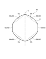
- FIG. 1 is a schematic diagram showing a tangent angle ⁇ , which is the angle between a tangent to a hypotenuse portion of a coil and a plane perpendicular to a parallel portion.
- 4 is a schematic diagram showing the relationship between magnetic pole pitch and coil pitch in a coreless motor.
- FIG. 1 is a schematic diagram showing the overall length of the coil along the axial direction of the center C and the length of the parallel portion.
- FIG. 1 is a graph showing the relationship between the tangent angle ⁇ of the coil and the cross-sectional area of the copper wire in a plane perpendicular to the parallel portion.
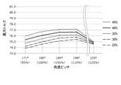
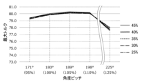
- 13 is a graph showing the maximum torque output by one turn of wire in a coil when the ratio of the coil pitch to the magnetic pole pitch (180°, as an example) is 0.95, 1.00, 1.05, 1.10, 1.25 (171, 180, 189, 198, 225°) for each coil having a tangent angle of 38.4° and a ratio of the length of the parallel portion to the total length of the coil set to 0.25, 0.30, 0.35, 0.40, 0.45.
- 13 is a graph showing the maximum torque output by one turn of wire in a coil when the ratio of the coil pitch to the magnetic pole pitch (180°, as an example) is 0.95, 1.00, 1.05, 1.10, 1.25 (171, 180, 189, 198, 225°) for each coil having a tangent angle of 32.0° and a ratio of the length of the parallel portion to the total length of the coil set to 0.25, 0.30, 0.35, 0.40, 0.45.
- 13 is a graph showing the maximum torque output by one turn of wire in a coil when the ratio of the coil pitch to the magnetic pole pitch (180°, for example) is 0.95, 1.00, 1.05, 1.10, 1.25 (171, 180, 189, 198, 225°) for each coil having a tangent angle of 25.6° and a ratio of the length of the parallel portion to the total length of the coil set to 0.25, 0.30, 0.35, 0.40, 0.45.
- 13 is a graph showing the maximum torque output by one turn of wire in a coil when the ratio of the coil pitch to the magnetic pole pitch (180°, as an example) is 0.95, 1.00, 1.05, 1.10, 1.25 (171, 180, 189, 198, 225°) for each coil having a tangent angle of 15.0° and a ratio of the length of the parallel portion to the total length of the coil set to 0.25, 0.30, 0.35, 0.40, 0.45.
- This graph shows the maximum torque output by one turn of wire in a coil when the tangent angles are 38.4, 32.0, 25.6, and 15.0° for each coil in which the ratio of coil pitch to magnetic pole pitch (180° as an example) is 0.95 (171°) and the ratio of the length of the parallel portion to the total length of the coil is set to 0.25, 0.30, 0.35, 0.40, and 0.45.
- 13 is a graph showing the maximum torque output by one turn of wire in a coil when the tangent angles are 38.4, 32.0, 25.6, and 15.0° for each coil in which the ratio of coil pitch to magnetic pole pitch (180° as an example) is 1.00 (180°) and the ratio of the length of the parallel portion to the total length of the coil is set to 0.25, 0.30, 0.35, 0.40, and 0.45.
- This graph shows the maximum torque output by one turn of wire in a coil when the tangent angles are 38.4, 32.0, 25.6, and 15.0° for each coil in which the ratio of coil pitch to magnetic pole pitch (180° as an example) is 1.05 (189°) and the ratio of the length of the parallel portion to the total length of the coil is set to 0.25, 0.30, 0.35, 0.40, and 0.45.
- This graph shows the maximum torque output by one turn of wire in a coil when the tangent angles are 38.4, 32.0, 25.6, and 15.0° for each coil in which the ratio of coil pitch to magnetic pole pitch (180° as an example) is 1.10 (198°) and the ratio of the length of the parallel portion to the total length of the coil is set to 0.25, 0.30, 0.35, 0.40, and 0.45.
- This graph shows the maximum torque output by one turn of wire in a coil when the tangent angles are 38.4, 32.0, 25.6, and 15.0° for each coil in which the ratio of coil pitch to magnetic pole pitch (180° as an example) is 1.25 (225°) and the ratio of the length of the parallel portion to the total length of the coil is set to 0.25, 0.30, 0.35, 0.40, and 0.45.
- FIG. 1 is a cross-sectional view of a coreless motor 100, showing a longitudinal section including the center C of the rotating shaft 20,
- FIG. 2 is a perspective view showing the coil 60 of the coreless motor 100 shown in FIG. 1, and
- FIGS. 3A, 3B, and 3C are schematic diagrams showing the process of manufacturing the coil 60.
- the coreless motor 100 is one embodiment of a coreless motor according to the present invention.
- the coreless motor 100 includes a rotating shaft 20, a coil 60, a commutator 50, a magnet 30, brushes 40, and a housing 10.
- the housing 10 is formed in a hollow cylindrical shape with both ends closed.
- the housing 10 houses a rotating shaft 20, a coil 60, a commutator 50, a magnet 30, and a brush 40 inside the hollow interior, and both ends of the rotating shaft 20 protrude outside the housing 10.
- the housing 10 includes a case 11 and a brush stand 12.
- the case 11 is formed in a cylindrical shape with one end closed.
- the case 11 is formed of a soft magnetic material such as metal.
- the case 11 may be formed of multiple members.
- the brush base 12 is formed in a generally circular plate shape so as to close the open end of the case 11.
- the brush base 12 is formed of resin, for example.
- the brush base 12 is provided with a conductor connection member (not shown) that is connected to an external power source, and a brush 40 that is electrically connected to this connection member.
- a rotating shaft 20 is disposed at center C, which is the axis of the cylinder of the housing 10, penetrating the housing 10 and being rotatable around center C.
- a commutator 50 is fixed to the rotating shaft 20.
- a coil 60 is fixed to the commutator 50.
- the rotating shaft 20, coil 60, and commutator 50 form a rotor.
- the coil 60 is formed into a cylindrical shape by winding a conductor 61 (see FIGS. 3A and 3B).
- the coil 60 rotates integrally with the rotating shaft 20, with the center C of the rotating shaft 20 as its axis.
- the coil 60 is formed by assembling a plurality of coil elements, each of which is wound with a conductor 61.
- the coil 60 is formed so that the outer peripheral surface 60A of the cylinder does not come into contact with the inner peripheral surface 11B of the case 11. Details of the coil 60 will be described later.
- the commutator 50 is formed in a disk shape with a boss in the center through which the rotating shaft 20 passes.
- the outer periphery of the disk of the commutator 50 is bonded with an adhesive to the inner periphery of one end of the cylindrical coil 60 that is closer to the brush base 12, and is integrated with the coil 60.
- the commutator 50 is integrally connected to the rotating shaft 20 that passes through the boss, and as a result, the commutator 50 rotates around the center C together with the rotating shaft 20.
- the commutator 50 has a conductive member that is electrically connected to the terminals 61a, 61b (see Figures 2, 3A, and 3B) of each of the conductors 61 of the multiple coil elements that make up the coil 60, and this conductive member extends to the outer circumferential surface of the boss and contacts the brush 40 provided on the brush stand 12.
- the magnet 30 is arranged inside the cylinder of the coil 60 so as not to come into contact with the inner peripheral surface 60B of the coil 60.
- the magnet 30 is formed in a cylindrical shape with the center C as its axis.
- the magnet 30 is formed so that the outer peripheral surface 30A does not come into contact with the inner peripheral surface 60B of the coil 60.
- the inner peripheral surface 30B of the magnet 30 is fixed to the outer peripheral surface of a cylindrical support member 28 fixed to the case 11.
- the magnet 30 is indirectly fixed to the case 11 and does not displace relative to the case 11.
- Bearings 25 are arranged on both ends of the support member 28 in the longitudinal direction inside the support member 28, and the rotating shaft 20 is supported by these two bearings 25 so that it can rotate freely.
- the coil 60 is basically made up of conductors 61 joined together with adhesive, and does not have a core such as an iron core. For this reason, the coil 60 is lighter than a coil with a core.
- the coil 60 is formed by winding a conductor 61 (e.g., copper wire) around the outer surface of a winding jig 500 that has a hexagonal cross section, e.g., a hexagonal prism shape.
- a conductor 61 e.g., copper wire
- the position at which the conductor 61 is wound is shifted slightly in the axial direction of the hexagonal prism for each turn of the winding (one turn around the outer surface of the hexagonal prism), so that when one turn of the coil 60 is projected in the axial direction, it has a hexagonal shape (tortoiseshell shape), forming a hexagonal spiral coil 60 as a whole.
- the hexagonal shapes formed by the conductor 61 are shown as being separate and independent, but this is for the convenience of simplifying the illustration.
- the conductor 61 shown as multiple hexagons has both ends of one turn of conductor 61 in each hexagon connected to the ends of one turn of conductor 61 in the adjacent hexagon to form a single spiral, and this single spiral conductor 61 has two terminals 61a, 61b.
- the conductor 61 for one turn of the coil 60 has a tortoiseshell (hexagonal) shape that corresponds to the cross-sectional shape of the winding jig 500.
- this tortoiseshell shape has a parallel portion 62 extending parallel to the axis (center C) of the rotating shaft 20, and two oblique portions 63, 64 connected to both ends of the parallel portion 62.
- the conductor 61 at the oblique portions 63, 64 extends linearly in a direction inclined at a predetermined angle with respect to a plane perpendicular to the center C.
- the inclination angle of the oblique portion 63 and the inclination angle of the oblique portion 64 differ in direction but have the same absolute value.
- the coil 60 shown in FIG. 3B is then deformed so that the linear hypotenuses 63, 64 shown by the two-dot chain lines in FIG. 3C are convex from the inside to the outside of one turn (hexagonal shape) of the coil 60, forming an outwardly convex curved shape shown by the solid line in FIG. 3C.
- this curve is, for example, a circular arc, but in the coreless motor according to the present invention, the coil curve is not limited to a circular arc.
- the coil curve may be an elliptical arc, a parabola, or multiple connected straight lines that approximate these curves (circular arc, elliptical arc, parabola).
- the coil 60 of the shape shown in FIG. 3C is used as one coil element, and multiple such coil elements are connected in the axial direction of the hexagonal prism described above, and the ends in the axial direction are connected around the center C shown in FIG. 3B so that one face 60A of the planar coil element faces outward (outer circumferential face) and the other face 60B faces inward (inner circumferential face), forming the cylindrical coil 60 shown in FIG. 2.
- the method of forming the curve of the coil 60 is not limited to the method described above.
- a columnar winding jig may be used in which the two peripheral surfaces of the hexagonal column that correspond to the parallel portion 62 are formed as flat surfaces, and the remaining four peripheral surfaces are formed as curved surfaces that convex outward rather than as flat surfaces, and the conductor wire 61 is wound around the jig to form the curve of the coil 60.
- This forming method allows the curve of the coil 60 to be formed accurately and easily.
- the coil 60 thus formed is a tortoiseshell-shaped (hexagonal) coil 60, and as shown in FIG. 2, on both the outer peripheral surface 60A and the inner peripheral surface 60B, the conductor 61 has a parallel portion 62 extending parallel to the axis (center C) of the rotating shaft 20, a hypotenuse portion 63 connected to one end of the parallel portion 62, and a hypotenuse portion 64 connected to the other end of the parallel portion 62.
- the conductor 61 of each of the oblique sides 63, 64 is tangent at the end of the coil 60 in the longitudinal direction along the parallel part 62 (the axial direction of the center C) to a plane perpendicular to the extension direction of the parallel part 62 at a predetermined angle ⁇ .
- this angle ⁇ will be referred to as the tangent angle ⁇ of the hypotenuses 63 and 64. Note that in FIG. 5, the tangent angle ⁇ is drawn only to the left of the center C on the paper, but it also exists to the right of the center C, so as to be linearly symmetric with respect to the center C.
- the parallel portion 62 on the outer peripheral surface 60A of the coil 60 is referred to as parallel portion 62a
- the parallel portion 62 on the inner peripheral surface 60B is referred to as parallel portion 62b.
- the oblique portions 63, 64 on the outer peripheral surface 60A of the coil 60 are referred to as oblique portions 63a, 64a
- the oblique portions 63, 64 on the inner peripheral surface 60B are referred to as oblique portions 63b, 64b.
- FIG. 4 is a schematic diagram showing the positional relationship between the magnet 30 and one turn of the hexagonal shape of the coil 60.
- the magnet 30 in the coreless motor 100 of this embodiment is formed, for example, with one north pole 30N and one south pole 30S on either side of the axis of the center C, as shown in FIG. 4.
- the magnet 30 is formed with the north pole 30N and the south pole 30S arranged at an angular interval (angular pitch) of 180 degrees around the axis of the center C of the magnet 30.
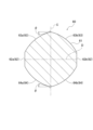
- Figure 6 is a schematic diagram showing the relationship between magnetic pole pitch ⁇ and coil pitch ⁇ in the coreless motor 100, and also shows the magnetic force distribution expressed by trigonometric functions, where the magnetic force of the magnet 30 is maximum at the center of the north pole 30N and the center of the south pole 30S.
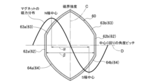
- Figure 7 is a schematic diagram showing the total length L0 along the axial direction of the center C of the coil 60 and the length L1 of the parallel portion 62.
- the center of the north pole 30N (north pole center) and the center of the south pole 30S (south pole center) of the magnet 30 are the angular positions where the absolute value of the magnetic force distribution of the magnet 30 is maximum.
- the angular pitch (angular interval) between the center of the north pole 30N and the center of the south pole 30S of the magnet 30 along the circumferential direction D around the axis of the center C is referred to as the magnetic pole pitch ⁇ .
- the coil 60 in the coreless motor 100 of this embodiment is formed by arranging two parallel parts 62, 62 of one turn of a hexagonal shape (see FIG. 5) at an angular interval (angular pitch) around the axis of the center C of the magnet 30, as shown in FIG. 6.
- the angular pitch (angular interval) between the two parallel parts 62, 62 of the coil 60 in the circumferential direction D around the axis of the center C is referred to as the coil pitch ⁇ .
- the coil 60 has, as an example, a ratio of the coil pitch ⁇ to the magnetic pole pitch ⁇ (angle pitch ratio) ⁇ / ⁇ set to a range of 1.00 (100[%]) or more and 1.25 (125[%]) or less.
- the magnetic pole pitch ⁇ of the magnet 30 in the coreless motor 100 is, for example, 180[degrees]
- an angle pitch ratio of 1.00 (100[%]) corresponds to a coil pitch ⁇ of 180[degrees]
- an angle pitch ratio of 1.25 (125[%]) corresponds to a coil pitch ⁇ of 225[degrees].
- the coreless motor 100 has a coil 60 in which the ratio (length ratio) L1/L0 of the length L1 of the parallel portion 62 to the total length L0 along the axial direction of the center C, as shown in FIG. 7, is set, for example, in the range of 0.25 (25% or more) and 0.75 (75% or less).
- T 2*B*I*r*L*sin ⁇ i (1)
- B is the magnetic flux from the magnet 30
- I is the current flowing through the coil 60
- r is the radius of the coil 60 (the dimension along the radial direction R)
- L is the length of the coil 60 (the dimension along the center C).
- ⁇ i is the inclination angle of the conductor 61 in the coil 60 with respect to a plane perpendicular to the direction of the center C (90 degrees at the parallel portion 62, ⁇ [ The values represent the change from [degrees].
- the maximum torque T output by the coreless motor 100 is greater as the area of the shaded region in FIG. 5 becomes larger. Therefore, in the coreless motor 100 of this embodiment, the coil 60 has a larger area of the shaded portion shown in FIG. 5 compared to a coil having straight hypotenuses 63, 64 shown by the two-dot chain lines in FIG. 3C, so that the magnetic flux acting on the coil 60 as a whole increases, and the maximum torque T output, which is a characteristic of the coreless motor 100, can be increased.
- the cross-sectional area of the conductor 61 (copper wire) at the end of the length direction of the coil 60 of the oblique sides 63 and 64, which is perpendicular to the parallel portion 62 increases as the tangent angle ⁇ is reduced, as shown in Table 1 and FIG. 8.
- the specific value of the cross-sectional area of the conductor 61 shown in Table 1 and FIG. 8 is an example in which the diameter of the conductor 61 is 0.1 mm. Therefore, in this example, the cross-sectional area of the conductor 61 at the parallel portion 62, which is perpendicular to the parallel portion 62, is 0.0078 mm 2 .
- FIG. 8 is a graph of Table 1.
- the tangent angle ⁇ is in a range in which the cross-sectional area of the conductor 61 does not increase rapidly with a decrease in the tangent angle ⁇ , that is, the space factor at the parallel part 62 does not fall below about 30%, that is, the cross-sectional area of the conductor 61 at the oblique sides 63 and 64 does not exceed three times the cross-sectional area of the conductor 61 at the parallel part 62, is in a range of 15 degrees or more, and in particular, it is preferable that the tangent angle ⁇ is in a range of 20 degrees or more, in which the space factor of the conductor 61 at the parallel part 62 and the thickness of the end of the coil 60 in the longitudinal direction are in a more practical range.
- the maximum torque T output by the coreless motor 100 drops to an impractical value when the tangent angle ⁇ of the oblique sides 63, 64 exceeds 50 degrees. Therefore, from the viewpoint of keeping the maximum torque T output by the coreless motor 100 within a practical range, it is preferable that the tangent angle ⁇ be 50 degrees or less, and even more preferable.
- the tangent angle ⁇ is 15 degrees or more and 50 degrees or less, and more preferably 20 degrees or more and 50 degrees or less, and even more preferably 20 degrees or more and 35 degrees or less.
- the tangent angle ⁇ of the coil 60 is set to 38.4 degrees, 32.0 degrees, 25.6 degrees, and 15.0 degrees, respectively.
- the ratio of the coil pitch ⁇ to the magnetic pole pitch ⁇ (angle pitch ratio) ⁇ / ⁇ is changed from 0.95 (95%) to 1.25 (125%)
- the ratio of the length L1 of the parallel portion 62 to the total length L0 of the coil 60 (length ratio) L1/L0 is changed from 0.25 (25%) to 0.45 (45%).
- the maximum torques output by one turn of the conductor 61 of the coil 60 of the coreless motor 100 are shown in Tables 2 to 5 and Figures 9 to 12.
- Figures 9 to 12 are graphs of Tables 2 to 5, respectively.
- the smaller the tangent angle ⁇ of the coreless motor 100 of this embodiment the greater the maximum torque T that the coreless motor 100 can output.
- the angular pitch ratio ⁇ / ⁇ is in the range of more than 1.00 (100[%]) to 1.10 (110[%])
- the greater the length ratio L1/L0 the greater the maximum torque T that the coreless motor 100 can output.
- the tangent angle ⁇ is in the range of 15 degrees or more and 50 degrees or less.
- the tangent angle ⁇ is in the range of 20 degrees or more and 35 degrees or less in order to minimize the increase in the cross-sectional area of the conductor 61 at the oblique sides 63 and 64.
- the angular pitch ratio ⁇ / ⁇ of the coreless motor 100 of this embodiment is in the range of more than 1.00 (100% ) and less than or equal to 1.10 (110% ), and in particular, it is preferable that the angular pitch ratio ⁇ / ⁇ is in the range of 1.05 (105% ) or more and less than or equal to 1.10 (110% ), which is the range in which the maximum torque T is maximized.
- the coreless motor 100 of this embodiment preferably has a length ratio L1/L0 in the range of 0.25 (25% ) or more and 0.75 (75% ) or less, and in particular, it is preferable that the length ratio L1/L0 be in the range of 0.25 (25% ) or more and 0.45 (45% ) or less.
- the tangent angle ⁇ is in the range of 15 degrees or more and 50 degrees or less, and the length ratio L1/L0 is in the range of 0.25 (25%) or more and 0.75 (75%) or less, it is preferable that the angular pitch ratio ⁇ / ⁇ is in the range of more than 1.00 (100%) and 1.10 (110%) or less.
- the coreless motor 100 can obtain an output that exceeds the maximum torque T when the angular pitch ratio ⁇ / ⁇ is 1.00 (100%), even if the angular pitch ratio ⁇ / ⁇ is in the range from over 1.00 (100%) to 1.25 (125%), that is, even if the upper limit of the angular pitch ratio ⁇ / ⁇ is raised from 1.10 (110%) to 1.25 (125%).
- the coreless motor 100 can obtain an output that exceeds the maximum torque T when the angular pitch ratio ⁇ / ⁇ is 1.00 (100%), even if the angular pitch ratio ⁇ / ⁇ is in the range from over 1.00 (100%) to 1.15 (115%), that is, even if the upper limit of the angular pitch ratio ⁇ / ⁇ is raised from 1.10 (110%) to 1.15 (115%).
- the coreless motor 100 can have an angular pitch ratio ⁇ / ⁇ in the range of more than 1.00 (100%) to 1.25 (125%).
- the angular pitch ratio ⁇ / ⁇ can be in the range of more than 1.00 (100%) to 1.15 (115%).
- the greater the length ratio L1/L0 the greater the maximum torque T that can be output.
- the cross-sectional area of the conductor 61 in the aforementioned oblique portions 63 and 64 increases, and the space factor of the conductor 61 in the parallel portion 62 decreases.
- the space factor of the conductor 61 in the parallel portion 62 becomes smaller than a predetermined value, the strength of the parallel portion 62 decreases, and the coil 60 may be deformed by the centrifugal force acting when rotating around the center C, and may come into contact with the housing 10. For this reason, the coil 60 needs to have a strength sufficient to prevent it from deforming at the rated rotation of the coreless motor 100.
- the upper limit of the length ratio L1/L0 is set to 0.75 (75%), taking into account the required strength of the coil 60.
- the upper limit of the length ratio L1/L0 of the coreless motor 100 is set to 0.45 (45%).
- the coreless motor 100 of this embodiment has a lower limit of 0.25 (25%) for the length ratio L1/L0 of the coil 60, because this makes it easier for the coreless motor 100 to output the normally required minimum maximum torque T. If the length ratio L1/L0 is less than 0.25 (25%), it becomes difficult for the coreless motor 100 to output a sufficient maximum torque T.
- the tangent angle ⁇ is set in the range of 15 degrees or more and 50 degrees or less
- the angular pitch ratio ⁇ / ⁇ is set in the range of more than 1.00 and 1.25 or less
- the length ratio L1/L0 is set in the range of 0.25 or more and 0.75 or less.
- the tangent angle ⁇ is set in the range of 20 degrees or more and 35 degrees or less
- the angular pitch ratio ⁇ / ⁇ is set in the range of 1.05 or more and 1.10 or less
- the length ratio L1/L0 is set in the range of 0.25 or more and 0.45 or less.
- the coreless motor 100 of this embodiment in which the tangent angle ⁇ , the angular pitch ratio ⁇ / ⁇ , and the length ratio L1/L0 are each set as described above, is a practical coreless motor that outputs a large maximum torque T.
- the coreless motor 100 of this embodiment can increase the maximum torque T output by, for example, up to about 10% compared to a conventional coreless motor equipped with a hexagonal (tortoiseshell) coil in which the oblique sides 63, 64 are formed in a straight line.
- the coreless motor 100 in the above-described embodiment is an outer rotor type coreless motor in which the coil 60 is arranged on the outside of the magnet 30, but the coreless motor according to the present invention is not limited to an outer rotor type coreless motor, and may be an inner rotor type coreless motor in which the coil 60 is arranged on the inside of the magnet 30.
- the outer peripheral surface of the magnet 30 is fixed to, for example, the inner peripheral surface of the case 11.
- the magnet 30 of the coreless motor 100 in the embodiment described above has one north pole 30N and one south pole 30S, but the magnet of the coreless motor according to the present invention may have two north poles 30N and two south poles 30S, or may have more magnetic poles.
Landscapes
- Engineering & Computer Science (AREA)
- Power Engineering (AREA)
- Dc Machiner (AREA)
- Windings For Motors And Generators (AREA)
Priority Applications (5)
| Application Number | Priority Date | Filing Date | Title |
|---|---|---|---|
| KR1020257027051A KR20250135844A (ko) | 2023-03-28 | 2023-03-28 | 코어리스 모터 |
| EP23930388.6A EP4693853A1 (en) | 2023-03-28 | 2023-03-28 | Coreless motor |
| CN202380091999.2A CN120604440A (zh) | 2023-03-28 | 2023-03-28 | 无芯电机 |
| JP2025509367A JP7850344B2 (ja) | 2023-03-28 | 2023-03-28 | コアレスモータ |
| PCT/JP2023/012646 WO2024201748A1 (ja) | 2023-03-28 | 2023-03-28 | コアレスモータ |
Applications Claiming Priority (1)
| Application Number | Priority Date | Filing Date | Title |
|---|---|---|---|
| PCT/JP2023/012646 WO2024201748A1 (ja) | 2023-03-28 | 2023-03-28 | コアレスモータ |
Publications (1)
| Publication Number | Publication Date |
|---|---|
| WO2024201748A1 true WO2024201748A1 (ja) | 2024-10-03 |
Family
ID=92903572
Family Applications (1)
| Application Number | Title | Priority Date | Filing Date |
|---|---|---|---|
| PCT/JP2023/012646 Ceased WO2024201748A1 (ja) | 2023-03-28 | 2023-03-28 | コアレスモータ |
Country Status (5)
| Country | Link |
|---|---|
| EP (1) | EP4693853A1 (https=) |
| JP (1) | JP7850344B2 (https=) |
| KR (1) | KR20250135844A (https=) |
| CN (1) | CN120604440A (https=) |
| WO (1) | WO2024201748A1 (https=) |
Citations (3)
| Publication number | Priority date | Publication date | Assignee | Title |
|---|---|---|---|---|
| JPS5256305A (en) * | 1975-11-01 | 1977-05-09 | Sony Corp | Coreless motor |
| JPS5523788A (en) | 1979-06-18 | 1980-02-20 | Sony Corp | Coil and coil bobbin for motor or generator and manufacture of coil |
| JP2014054026A (ja) | 2012-09-05 | 2014-03-20 | Canon Electronics Inc | コアレスコイル、モータ及びコアレスコイルの製造方法 |
-
2023
- 2023-03-28 EP EP23930388.6A patent/EP4693853A1/en active Pending
- 2023-03-28 WO PCT/JP2023/012646 patent/WO2024201748A1/ja not_active Ceased
- 2023-03-28 KR KR1020257027051A patent/KR20250135844A/ko active Pending
- 2023-03-28 JP JP2025509367A patent/JP7850344B2/ja active Active
- 2023-03-28 CN CN202380091999.2A patent/CN120604440A/zh active Pending
Patent Citations (3)
| Publication number | Priority date | Publication date | Assignee | Title |
|---|---|---|---|---|
| JPS5256305A (en) * | 1975-11-01 | 1977-05-09 | Sony Corp | Coreless motor |
| JPS5523788A (en) | 1979-06-18 | 1980-02-20 | Sony Corp | Coil and coil bobbin for motor or generator and manufacture of coil |
| JP2014054026A (ja) | 2012-09-05 | 2014-03-20 | Canon Electronics Inc | コアレスコイル、モータ及びコアレスコイルの製造方法 |
Also Published As
| Publication number | Publication date |
|---|---|
| KR20250135844A (ko) | 2025-09-15 |
| JP7850344B2 (ja) | 2026-04-22 |
| JPWO2024201748A1 (https=) | 2024-10-03 |
| EP4693853A1 (en) | 2026-02-11 |
| CN120604440A (zh) | 2025-09-05 |
Similar Documents
| Publication | Publication Date | Title |
|---|---|---|
| US8890387B2 (en) | Stator and motor | |
| US7269890B2 (en) | Slotless rotary electric machine and manufacturing method of coils for such a machine | |
| US7368843B2 (en) | Commutator motor | |
| US9287744B2 (en) | Winding structure, rotating electric machine, and rotating electric machine manufacturing method | |
| CN103516081B (zh) | 转子、具有转子的发电-电动机及转子制造方法 | |
| JP2012228104A (ja) | 永久磁石埋込型電動機 | |
| JP4444737B2 (ja) | ブラシレスモータ及びパワーステアリング装置用モータ | |
| CN112640274B (zh) | 轴向磁通电机 | |
| US20040056557A1 (en) | Epicycloidal motor | |
| JP5248751B2 (ja) | スロットレス永久磁石型回転電機 | |
| JP6138360B2 (ja) | 回転電機およびその製造方法 | |
| CN116345764A (zh) | 用于旋转电机的电磁极、包括该电磁极的转子和旋转电机 | |
| WO2024201748A1 (ja) | コアレスモータ | |
| US20170279318A1 (en) | Rotary electrical machine with a ratio of dimensions which minimises the torque undulations | |
| JP6843272B2 (ja) | 回転電機の固定子及び回転電機の固定子の製造方法 | |
| WO2024201747A1 (ja) | コアレスモータ | |
| GB2092833A (en) | Flat coil element for an electric motor and method of manufacturing the same | |
| JP2021535718A (ja) | リングコイル及び蛇行コイルを有するクローポールモータ | |
| US20100289375A1 (en) | Stator Core | |
| US20170279320A1 (en) | Rotary electrical machine with a configuration which minimises the torque undulations | |
| JP7515028B1 (ja) | コアレスモータ | |
| JP2004080950A (ja) | 回転電機の電機子 | |
| JP7195180B2 (ja) | 固定子、及び回転電機 | |
| JP5230303B2 (ja) | ステッピングモータ | |
| US6891307B2 (en) | Motor with a plurality of pole teeth |
Legal Events
| Date | Code | Title | Description |
|---|---|---|---|
| 121 | Ep: the epo has been informed by wipo that ep was designated in this application |
Ref document number: 23930388 Country of ref document: EP Kind code of ref document: A1 |
|
| WWE | Wipo information: entry into national phase |
Ref document number: 2025509367 Country of ref document: JP |
|
| WWE | Wipo information: entry into national phase |
Ref document number: 202380091999.2 Country of ref document: CN |
|
| WWE | Wipo information: entry into national phase |
Ref document number: 202517074720 Country of ref document: IN |
|
| ENP | Entry into the national phase |
Ref document number: 1020257027051 Country of ref document: KR Free format text: ST27 STATUS EVENT CODE: A-0-1-A10-A15-NAP-PA0105 (AS PROVIDED BY THE NATIONAL OFFICE) |
|
| WWE | Wipo information: entry into national phase |
Ref document number: 1020257027051 Country of ref document: KR |
|
| WWP | Wipo information: published in national office |
Ref document number: 202380091999.2 Country of ref document: CN |
|
| WWP | Wipo information: published in national office |
Ref document number: 202517074720 Country of ref document: IN |
|
| WWE | Wipo information: entry into national phase |
Ref document number: 2023930388 Country of ref document: EP |
|
| NENP | Non-entry into the national phase |
Ref country code: DE |
|
| ENP | Entry into the national phase |
Ref document number: 2023930388 Country of ref document: EP Effective date: 20251028 |
|
| ENP | Entry into the national phase |
Ref document number: 2023930388 Country of ref document: EP Effective date: 20251028 |
|
| ENP | Entry into the national phase |
Ref document number: 2023930388 Country of ref document: EP Effective date: 20251028 |
|
| ENP | Entry into the national phase |
Ref document number: 2023930388 Country of ref document: EP Effective date: 20251028 |
|
| ENP | Entry into the national phase |
Ref document number: 2023930388 Country of ref document: EP Effective date: 20251028 |
|
| ENP | Entry into the national phase |
Ref document number: 2023930388 Country of ref document: EP Effective date: 20251028 |
|
| ENP | Entry into the national phase |
Ref document number: 2023930388 Country of ref document: EP Effective date: 20251028 |
|
| ENP | Entry into the national phase |
Ref document number: 2023930388 Country of ref document: EP Effective date: 20251028 |
|
| WWP | Wipo information: published in national office |
Ref document number: 2023930388 Country of ref document: EP |