WO2024201720A1 - 海底光通信システム、その制御方法、及び、制御プログラムが格納された非一時的なコンピュータ可読媒体 - Google Patents
海底光通信システム、その制御方法、及び、制御プログラムが格納された非一時的なコンピュータ可読媒体 Download PDFInfo
- Publication number
- WO2024201720A1 WO2024201720A1 PCT/JP2023/012547 JP2023012547W WO2024201720A1 WO 2024201720 A1 WO2024201720 A1 WO 2024201720A1 JP 2023012547 W JP2023012547 W JP 2023012547W WO 2024201720 A1 WO2024201720 A1 WO 2024201720A1
- Authority
- WO
- WIPO (PCT)
- Prior art keywords
- partial
- cores
- multicore fiber
- faulty
- submarine
- Prior art date
- Legal status (The legal status is an assumption and is not a legal conclusion. Google has not performed a legal analysis and makes no representation as to the accuracy of the status listed.)
- Ceased
Links
Images



Classifications
-
- H—ELECTRICITY
- H04—ELECTRIC COMMUNICATION TECHNIQUE
- H04B—TRANSMISSION
- H04B10/00—Transmission systems employing electromagnetic waves other than radio-waves, e.g. infrared, visible or ultraviolet light, or employing corpuscular radiation, e.g. quantum communication
- H04B10/03—Arrangements for fault recovery
-
- H—ELECTRICITY
- H04—ELECTRIC COMMUNICATION TECHNIQUE
- H04B—TRANSMISSION
- H04B10/00—Transmission systems employing electromagnetic waves other than radio-waves, e.g. infrared, visible or ultraviolet light, or employing corpuscular radiation, e.g. quantum communication
- H04B10/07—Arrangements for monitoring or testing transmission systems; Arrangements for fault measurement of transmission systems
- H04B10/075—Arrangements for monitoring or testing transmission systems; Arrangements for fault measurement of transmission systems using an in-service signal
Definitions
- the present disclosure relates to an undersea optical communication system, a control method thereof, and a non-transitory computer-readable medium on which a control program is stored.
- An undersea optical communication system comprises multiple terminal devices installed on land, an undersea cable that transmits communications between them, and undersea equipment installed at relay points of the undersea cable.
- the undersea equipment transmits, relays, and branches the optical signals propagating through the undersea cable.
- undersea cables made of multicore fibers, which are made up of multiple cores, for undersea optical communication systems is being considered.
- Patent Document 1 Technologies relating to undersea optical communication systems are disclosed, for example, in Patent Document 1, Patent Document 2, Patent Document 3, and Patent Document 4.
- Patent Document 2 when a multicore fiber in a cable fails, the transmission path of the signal transmitted through the failed multicore fiber is switched to a spare multicore fiber.
- the present disclosure has been made to solve these problems, and aims to provide an undersea optical communication system that can suppress increases in costs by optimizing communications without using a spare multicore fiber or spare cores even when a failure occurs in the multicore fiber of a cable, a control method thereof, and a non-transitory computer-readable medium on which a control program is stored.
- the undersea optical communication system comprises a plurality of terminal devices, a first multi-core fiber composed of a plurality of first cores that transmits an optical signal used for communication between the plurality of terminal devices, and a first subsea device and a second subsea device that are provided at a relay point of the first multi-core fiber and are configured to be able to switch the connection of the plurality of first cores that constitute the first multi-core fiber.
- At least one of the plurality of terminal devices comprises a monitoring circuit that monitors the signal transmission status of the first multi-core fiber, and a control circuit that, when the monitoring circuit determines that any of the plurality of first partial cores that constitute a first partial multi-core fiber provided between the first subsea device and the second subsea device of the first multi-core fiber is faulty, switches the transmission path of the optical signal transmitted by the first partial core determined to be faulty to another first partial core that transmits an optical signal with a lower priority than the first partial core determined to be faulty.
- the control method for an undersea optical communication system is a control method for an undersea optical communication system including a plurality of terminal devices, a first multi-core fiber composed of a plurality of first cores that transmits an optical signal used for communication between the plurality of terminal devices, and a first submarine device and a second submarine device that are provided at a relay point of the first multi-core fiber and configured to be able to switch the connection of the plurality of first cores that constitute the first multi-core fiber, and the control method monitors the signal transmission status of the first multi-core fiber using at least one of the plurality of terminal devices, and when it is determined that any of the plurality of first partial cores that constitute a first partial multi-core fiber provided between the first submarine device and the second submarine device of the first multi-core fiber is faulty, the control method switches the transmission path of the optical signal that was transmitted by the first partial core determined to be faulty to another first partial core that transmits an optical signal with a lower priority than the first partial core determined to be faulty
- the non-transient computer-readable medium on which the control program according to the present disclosure is stored is a non-transient computer-readable medium on which a control program that causes a computer to execute control processing in an undersea optical communication system including a plurality of terminal devices, a first multi-core fiber composed of a plurality of first cores that transmits an optical signal used for communication between the plurality of terminal devices, and a first submarine device and a second submarine device that are provided at a relay point of the first multi-core fiber and are configured to be able to switch the connection of the plurality of first cores that constitute the first multi-core fiber, is stored.
- the control program that causes a computer to execute the following processing is stored: monitoring the signal transmission status of the first multi-core fiber using at least one of the plurality of terminal devices; and, when it is determined that any of the plurality of first partial cores that constitute a first partial multi-core fiber provided between the first submarine device and the second submarine device of the first multi-core fiber is faulty, switching the transmission path of the optical signal that was transmitted by the first partial core determined to be faulty to another first partial core that transmits an optical signal with a lower priority than the first partial core determined to be faulty.
- the present disclosure provides an undersea optical communications system that can suppress increases in costs by optimizing communications without using a spare multicore fiber or spare cores even when a failure occurs in the multicore fiber of a cable, a control method thereof, and a non-transitory computer-readable medium storing a control program.
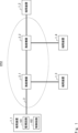
- FIG. 1 is a block diagram showing a configuration example of a submarine optical communication system according to a first embodiment
- FIG. 2 is a diagram for explaining the operation of the undersea optical communication system shown in FIG. 1
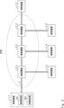
- FIG. 11 is a block diagram showing a configuration example of a submarine optical communication system according to a second embodiment.
- FIG. 4 is a diagram for explaining the operation of the undersea optical communication system shown in FIG. 3 .
- FIG. 11 is a block diagram showing a configuration example of a submarine optical communication system according to a third embodiment.
- FIG. 6 is a diagram for explaining the operation of the undersea optical communication system shown in FIG. 5 .
- FIG. 6 is a diagram for explaining the operation of the undersea optical communication system shown in FIG. 5 .
- FIG. 5 is a diagram for explaining the operation of the undersea optical communication system shown in FIG. 5 .
- FIG. 6 is a diagram for explaining the operation of the undersea optical communication system shown in FIG. 5 .
- FIG. 6 is a diagram for explaining the operation of the undersea optical communication system shown in FIG. 5 .
- FIG. 6 is a diagram for explaining the operation of the undersea optical communication system shown in FIG. 5 .
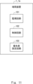
- FIG. 13 is a block diagram showing a modified example of the terminal device.
- the components are not necessarily essential unless otherwise specified or considered to be clearly essential in principle.
- the shape, positional relationship, etc. of components, etc. it is intended to include things that are substantially similar or approximate to the shape, etc., unless otherwise specified or considered to be clearly not essential in principle.
- Fig. 1 is a block diagram showing a configuration example of a submarine optical communication system SYS1 according to a first embodiment.
- Fig. 2 is a diagram for explaining the operation of the submarine optical communication system SYS1.
- the submarine optical communication system SYS1 includes multiple terminal devices 1, multiple submarine devices 2, and an undersea cable 3.
- the submarine optical communication system SYS1 includes four terminal devices 1_1 to 1_4 as the multiple terminal devices 1, and two submarine devices 2_1 to 2_2 as the multiple submarine devices 2.
- the terminal devices 1_1 to 1_4 are provided on land and are configured to be able to communicate with each other via an undersea cable 3.
- Each of the terminal devices 1_1 to 1_4 is equipped with, for example, a WME (Wavelength Multiplexing Equipment), an OCI (Open Cable Interface), an SLTE (Subscriber Line Terminal Equipment), a TPND (Transponder), etc.
- At least one of the terminal devices 1_1 to 1_4 is equipped with a monitoring circuit 101 and a control circuit 102. In this embodiment, an example will be described in which the terminal device 1_1 is equipped with the monitoring circuit 101 and the control circuit 102.
- the submarine cable 3 is an optical fiber cable that transmits optical signals used for communication between the terminal devices 1_1 to 1_4.
- the submarine cable 3 includes a multicore fiber composed of multiple cores.
- the submarine cable 3 includes a multicore fiber MCF1 composed of four cores.
- Each of the submarine devices 2_1-2_2 is provided at a relay point (undersea) of the submarine cable 3, and transmits, relays, and branches optical signals propagating through the submarine cable 3.
- the submarine devices 2_1-2_2 are configured to be able to switch the connection of the four cores that make up the multicore fiber MCF1 included in the submarine cable 3.
- the monitoring circuit 101 monitors the signal transmission status of the submarine cable 3. In other words, the monitoring circuit 101 monitors the signal transmission status of the multi-core fiber MCF1 included in the submarine cable 3.
- the control circuit 102 Based on the monitoring results by the monitoring circuit 101, the control circuit 102 causes the submarine devices 2_1-2_2 to switch the connections of the four cores that make up the multicore fiber MCF1. Note that a priority level is set for the optical signal to be transmitted for each core. Cores that transmit optical signals with a low priority level also include cores where the transmission of optical signals has temporarily stopped.
- the control circuit 102 switches the transmission path of the optical signal transmitted by the core determined to be faulty to another core transmitting an optical signal with a lower priority than the core determined to be faulty.
- the control circuit 102 switches the transmission path of the optical signal transmitted by the core C1a to the core C1d, which transmits an optical signal with a lower priority than the core C1a.
- the submarine optical communication system SYS1 can optimize communications even if a failure occurs in the submarine cable 3 without using a spare multicore fiber or spare cores, thereby reducing the costs associated with spare multicore fibers and spare cores.
- the submarine optical communication system SYS1 only requires switching the connection of the core portion between two submarine devices where a fault has occurred, among the cores of the submarine cable 3 installed between the terminal device 1_1 and the terminal device 1_2, to another core. This makes it possible to prevent momentary interruptions in cores that are not faulty.
- control circuit 102 switches the connection of multiple cores constituting the multicore fiber MCF1 provided between the submarine device 2_1 and the submarine device 2_2, but this is not limited to the above.
- the control circuit 102 may be configured to switch the connection of multiple cores constituting the multicore fiber MCF1 provided between the terminal device 1_1 and the submarine device 2_1, for example.
- the submarine optical communication system SYS1 is described as having two submarine devices 2_1 and 2_2, but this is not limited to the example.
- the submarine optical communication system SYS1 can be modified as appropriate to have a configuration including three or more submarine devices 2_1 to 2_n (n is an integer of 3 or more).
- Fig. 3 is a block diagram showing a configuration example of a submarine optical communication system SYS2 according to a second embodiment.
- Fig. 4 is a diagram for explaining the operation of the submarine optical communication system SYS2.
- the submarine optical communication system SYS2 includes five terminal devices 1_1 to 1_5 as the multiple terminal devices 1, and three submarine devices 2_1 to 2_3 as the multiple submarine devices 2.
- the other configurations of the submarine optical communication system SYS2 are similar to those of the submarine optical communication system SYS1, and therefore description thereof will be omitted.
- the submarine device 2_3 is provided at a relay point (undersea) of the submarine cable 3, and transmits, relays, and branches optical signals propagating through the submarine cable 3.
- the submarine devices 2_1 to 2_3 are also configured to be able to switch the connection of the four cores that make up the multicore fiber MCF1 included in the submarine cable 3.
- the control circuit 102 causes the submarine devices 2_1 to 2_3 to switch the connections of the four cores that make up the multicore fiber MCF1 based on the monitoring results from the monitoring circuit 101.
- the control circuit 102 causes the submarine devices 2_1 to 2_3 to individually switch between the connection of the four cores C1a to C1d constituting the multicore fiber MCF1_1 provided between the submarine devices 2_1 and 2_2, and the connection of the four cores (second partial cores) C2a to C2d constituting the multicore fiber (second partial multicore fiber) MCF1_2 provided between the submarine devices 2_2 and 2_3.
- the control circuit 102 switches the transmission path of the optical signal transmitted by the core C1a to the core C1d, which transmits an optical signal with a lower priority than the core C1a.
- the control circuit 102 switches the transmission path of the optical signal transmitted by the core C2c to the core C2d, which transmits an optical signal with a lower priority than the core C2c.
- the submarine optical communication system SYS2 can optimize communications even if a failure occurs in the submarine cable 3 without using a spare multicore fiber or spare cores, thereby reducing the costs associated with spare multicore fibers and spare cores.
- the submarine optical communication system SYS2 only needs to switch the connection of the core portion between the two submarine devices where a fault has occurred to another core among the cores of the submarine cable 3 installed between the terminal device 1_1 and the terminal device 1_2. This makes it possible to prevent momentary interruptions of cores and multi-core fibers that are not faulty.
- control circuit 102 switches the connection of multiple cores constituting the multicore fiber MCF1 provided between the submarine device 2_1 and the submarine device 2_2, but this is not limited to the above.
- the control circuit 102 may be configured to switch the connection of multiple cores constituting the multicore fiber MCF1 provided between the terminal device 1_1 and the submarine device 2_1, for example.
- Fig. 5 is a block diagram showing a configuration example of a submarine optical communication system SYS3 according to a third embodiment.
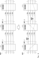
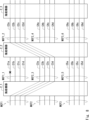
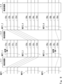
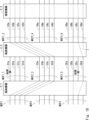
- Fig. 6 to Fig. 10 are diagrams for explaining the operation of the submarine optical communication system SYS3.
- Fig. 6 shows a part of the submarine optical communication system SYS3 before a failure occurs in the submarine cable
- Fig. 7 to Fig. 10 show a part of the submarine optical communication system SYS3 in a state in which the submarine cable has failed.
- the submarine optical communication system SYS3 has a submarine cable 4 instead of the submarine cable 3.
- the rest of the configuration of the submarine optical communication system SYS2 is the same as that of the submarine optical communication system SYS2, so the description thereof will be omitted.
- the submarine cable 4 includes multiple multi-core fibers.
- the submarine cable 4 includes three multi-core fibers MCF1 to MCF3.
- Each of the multi-core fibers MCF1 to MCF3 is composed of four cores.
- each of the multi-core fibers MCF1 to MCF3 may be composed of any number of cores.
- the submarine devices 2_1 to 2_3 are configured to be able to switch the connections of the four cores that make up each of the multicore fibers MCF1 to MCF3.
- the submarine devices 2_1 to 2_3 are configured to be able to switch the connections between the multicore fibers MCF1 to MCF3.
- the control circuit 102 causes the submarine devices 2_1 to 2_3 to switch the connections of the four cores that make up each of the multicore fibers MCF1 to MCF3 based on the monitoring results of the monitoring circuit 101.
- the control circuit 102 causes the submarine devices 2_1 to 2_3 to switch the connections between the multicore fibers MCF1 to MCF3 based on the monitoring results of the monitoring circuit 101.
- the monitoring circuit 101 determines that a core C1a, which is one of the cores C1a to C1d constituting the multi-core fiber MCF1_1 provided between the submarine device 2_1 and the submarine device 2_2 in the multi-core fiber MCF1, is faulty.
- the control circuit 102 switches the transmission path of the optical signal transmitted by the core C1a to a core C3a that transmits an optical signal with a lower priority than the core C1a.
- the core C3a is one of the cores C3a to C3d constituting the multi-core fiber MCF2_3 provided between the submarine device 2_1 and the submarine device 2_2 in the multi-core fiber MCF2.
- connection may be switched on a core-by-core basis between one multicore fiber and another multicore fiber.
- the monitoring circuit 101 determines that a core C1a, which is one of the cores C1a to C1d constituting the multi-core fiber MCF1_1 provided between the submarine device 2_1 and the submarine device 2_2, of the multi-core fiber MCF1, has a fault.
- the control circuit 102 switches the transmission path of the optical signal transmitted by the multi-core fiber MCF1_1 to the multi-core fiber MCF2_3 that transmits an optical signal having a lower priority than the multi-core fiber MCF1_1.
- connection may be switched between one multicore fiber and another multicore fiber on a multicore fiber basis.
- the monitoring circuit 101 determines that a core C1a, which is one of the cores C1a to C1d constituting the multi-core fiber MCF1_1 provided between the submarine device 2_1 and the submarine device 2_2, of the multi-core fiber MCF1, is faulty.
- the control circuit 102 switches the transmission path of the optical signal transmitted by the multi-core fiber MCF1_1 to the multi-core fiber MCF2_3 that transmits an optical signal having a lower priority than the multi-core fiber MCF1_1.
- the monitoring circuit 101 determines that a core C5c, which is one of the cores C5a to C5d constituting the multicore fiber MCF3_5 provided between the submarine device 2_1 and the submarine device 2_2, of the multicore fiber MCF3, has failed.
- the control circuit 102 switches the transmission path of the optical signal transmitted by the core C5c to the core C5d, which transmits an optical signal with a lower priority than the core C5c.
- cores and multi-core fibers that are no longer in use due to switching of the signal transmission path may be used to transmit optical signals supplied from the branch path.
- core C6d which is one of cores C6a to C6d constituting multi-core fiber MCF3_6 provided between submarine device 2_2 and submarine device 2_3 in multi-core fiber MCF3, is used to transmit optical signals supplied from the branch path.
- the submarine optical communication system SYS3 can optimize communications even if a failure occurs in the submarine cable 4 without using a spare multicore fiber or spare cores, thereby reducing the costs associated with spare multicore fibers and spare cores.
- the submarine optical communication system SYS3 according to this embodiment only needs to switch the connection of only the core portion between two submarine devices where a fault has occurred, among the cores of the submarine cable 4 installed between the terminal device 1_1 and the terminal device 1_2, to another core.
- the submarine optical communication system SYS3 according to this embodiment only needs to switch the connection of only the multi-core fiber portion between two submarine devices where a fault has occurred, among the multi-core fibers of the submarine cable 4 installed between the terminal device 1_1 and the terminal device 1_2, to another multi-core fiber. Therefore, it is possible to prevent momentary interruption of cores and multi-core fibers where no fault has occurred.
- the terminal device 1_1 may have a function to set a priority for each multi-core fiber and a function to set a priority for each of the multiple cores that make up each multi-core fiber. This will be explained in detail below with reference to FIG. 11.
- FIG. 11 shows a modified version of the terminal device 1_1 as terminal device 1_1a.
- the terminal device 1_1a further includes a priority setting circuit 103.
- the priority setting circuit 103 sets a priority for each multi-core fiber included in the submarine cable 4, and sets a priority for each of the multiple cores that make up each multi-core fiber.
- the priority setting circuit 103 can set a priority individually for each multi-core fiber provided between any two adjacent submarine devices, and for each of the multiple cores constituting each of the multi-core fibers. Similarly, the priority setting circuit 103 can set a priority individually for each multi-core fiber provided between any adjacent terminal device and submarine device, and for each of the multiple cores constituting each of the multi-core fibers.
- the priority setting circuit 103 may be configured to set different priorities depending on the time of day, such as morning, afternoon, or night, for each multi-core fiber provided between any two adjacent submarine devices and for each of the multiple cores constituting each multi-core fiber. Similarly, the priority setting circuit 103 may be configured to set different priorities depending on the time of day, for each multi-core fiber provided between any adjacent terminal device and submarine device and for each of the multiple cores constituting each multi-core fiber.
- the priority setting circuit 103 may be configured to set a common priority for the cores belonging to the first group among the multiple cores constituting each multicore fiber provided between any two adjacent undersea devices, and to set a common priority for the cores belonging to the second group. Similarly, the priority setting circuit 103 may set a common priority for the cores belonging to the first group among the multiple cores constituting each multicore fiber provided between any adjacent terminal equipment and undersea equipment, and to set a common priority for the cores belonging to the second group.
- the first group and the second group may be, for example, different companies, etc.
- the priority setting circuit 103 may be configured to set the highest priority to at least one core belonging to the first group and at least one core belonging to the second group among the multiple cores constituting each multicore fiber provided between any two adjacent submarine devices. Similarly, the priority setting circuit 103 may be configured to set the highest priority to at least one core belonging to the first group and at least one core belonging to the second group among the multiple cores constituting each multicore fiber provided between any adjacent terminal device and submarine device. This makes it possible to leave at least one core belonging to each group.
- the priority setting circuit 103 may also be configured to set priorities for the cores belonging to the first group and the cores belonging to the second group among the multiple cores constituting each multicore fiber provided between any two adjacent submarine devices, such that the ratio of their numbers is maintained. Similarly, the priority setting circuit 103 may also be configured to set priorities for the cores belonging to the first group and the cores belonging to the second group among the multiple cores constituting each multicore fiber provided between any adjacent terminal device and submarine device, such that the ratio of their numbers is maintained.
- the ratio of cores belonging to the first group and cores belonging to the second group will be maintained, and the number of cores belonging to the first group will be four and the number of cores belonging to the second group will be two.
- the present disclosure has been described as a hardware configuration, but the present disclosure is not limited to this.
- the present disclosure can also be realized by having a CPU (Central Processing Unit) execute a computer program for some or all of the control processing in the submarine optical communication system SYS1.
- a CPU Central Processing Unit
- the above-mentioned program includes a set of instructions (or software code) that, when loaded into a computer, causes the computer to perform one or more functions described in the embodiments.
- the program may be stored on a non-transitory computer-readable medium or a tangible storage medium.
- computer-readable media or tangible storage media include RAM (Random-Access Memory), ROM (Read-Only Memory), flash memory, SSD (Solid-State Drive) or other memory technology, CD-ROM, DVD (Digital Versatile Disc), Blu-ray (registered trademark) disk or other optical disk storage, magnetic cassette, magnetic tape, magnetic disk storage or other magnetic storage device.
- the program may be transmitted on a temporary computer-readable medium or communication medium.
- temporary computer-readable media or communication media include electrical, optical, acoustic, or other forms of transmission signals.
- a plurality of terminal devices A plurality of terminal devices; a first multi-core fiber configured by a plurality of first cores and transmitting an optical signal used for communication between the plurality of terminal devices; a first submarine device and a second submarine device that are provided at a relay point of the first multicore fiber and configured to be able to switch connections of a plurality of first cores that constitute the first multicore fiber; Equipped with At least one of the plurality of terminal devices is A monitoring circuit for monitoring a signal transmission status of the first multicore fiber; a control circuit that, when it is determined by the monitoring circuit that any one of a plurality of first partial cores constituting a first partial multicore fiber provided between the first submarine equipment and the second submarine equipment of the first multicore fiber is faulty, switches a transmission path of an optical signal transmitted by the first partial core determined to be faulty to another first partial core that transmits an optical signal having a lower priority than the first partial core determined to be faulty; An undersea optical communication system.
- At least one of the plurality of terminal devices is Further comprising a priority setting circuit that sets a priority of an optical signal to be transmitted for each of a plurality of first cores constituting the first multicore fiber.
- the priority setting circuit sets different priorities for each of the multiple first cores constituting the first multicore fiber depending on a time period. 3.
- the priority setting circuit sets a common priority for first cores belonging to a first group among the plurality of first cores constituting the first multicore fiber, and sets a common priority for first cores belonging to a second group; 3.
- the priority setting circuit sets the highest priority to at least one of the first cores belonging to a first group and at least one of the first cores belonging to a second group among the multiple first cores constituting the first multicore fiber; 3.
- the priority setting circuit sets priorities for the first cores belonging to a first group and the first cores belonging to a second group among the multiple first cores constituting the first multicore fiber such that a ratio between the number of the first cores belonging to the first group and the number of the first cores belonging to the second group is maintained.
- (Appendix 7) a third submarine device provided at a relay point of the first multicore fiber and configured to be able to switch connections of a plurality of first cores constituting the first multicore fiber; when the monitoring circuit determines that any one of a plurality of second partial cores constituting a second partial multicore fiber of the first multicore fiber provided between the second submarine equipment and the third submarine equipment is faulty, the control circuit switches a transmission path of an optical signal transmitted by the second partial core determined to be faulty to another second partial core transmitting an optical signal having a lower priority than the second partial core determined to be faulty.
- At least one of the plurality of terminal devices is A priority setting circuit is further provided that sets a priority of an optical signal to be transmitted for each of a plurality of first cores constituting the first multicore fiber,
- the priority setting circuit includes: setting a priority level for each of a plurality of first partial cores constituting a first partial multicore fiber provided between the first submarine equipment and the second submarine equipment, of the first multicore fiber, and setting a priority level for each of a plurality of second partial cores constituting a second partial multicore fiber provided between the second submarine equipment and the third submarine equipment, of the first multicore fiber; 8.
- the monitoring circuit further monitors a signal transmission status of the second multicore fiber, when the monitoring circuit determines that any one of a plurality of third partial cores constituting a third partial multicore fiber provided between the first submarine equipment and the second submarine equipment of the second multicore fiber is faulty, the control circuit switches a transmission path of an optical signal transmitted by the third partial core determined to be faulty to another third partial core transmitting an optical signal having a lower priority than the third partial core determined to be faulty.
- At least one of the plurality of terminal devices is a priority setting circuit that sets priorities of optical signals to be transmitted for each of a plurality of first cores constituting the first multicore fiber and each of a plurality of second cores constituting the second multicore fiber; 10.
- the priority setting circuit sets different priorities for each of a plurality of first cores constituting the first multicore fiber and each of a plurality of second cores constituting the second multicore fiber depending on a time period; 11.
- the priority setting circuit sets a common priority for first cores belonging to a first group among the plurality of first cores constituting the first multicore fiber, sets a common priority for first cores belonging to a second group, and sets a common priority for second cores belonging to a third group among the plurality of second cores constituting the second multicore fiber, and sets a common priority for second cores belonging to a fourth group.
- the priority setting circuit sets the highest priority to at least one of the first cores belonging to a first group and at least one of the first cores belonging to a second group among the multiple first cores constituting the first multicore fiber, and sets the highest priority to at least one of the second cores belonging to a third group and at least one of the second cores belonging to a fourth group among the multiple second cores constituting the second multicore fiber.
- the priority setting circuit sets priorities for each of the first cores belonging to a first group and each of the first cores belonging to a second group among the multiple first cores constituting the first multicore fiber, such that a ratio between the number of first cores belonging to the first group and the number of first cores belonging to the second group is maintained, and sets priorities for each of the second cores belonging to a third group and each of the second cores belonging to a fourth group among the multiple second cores constituting the second multicore fiber, such that a ratio between the number of second cores belonging to the third group and the number of second cores belonging to the fourth group is maintained.
- the control circuit includes: when the monitoring circuit determines that any one of a plurality of first partial cores constituting a first partial multicore fiber provided between the first submarine equipment and the second submarine equipment of the first multicore fiber is faulty, the monitoring circuit switches a transmission path of an optical signal transmitted by the first partial core determined to be faulty to another first partial core transmitting an optical signal having a lower priority than the first partial core determined to be faulty, or any one of a plurality of third partial cores constituting the third partial multicore fiber; and when the monitoring circuit determines that any one of a plurality of third partial cores constituting a third partial multicore fiber provided between the first submarine equipment and the second submarine equipment in the second multicore fiber is faulty, the monitoring circuit switches a transmission path of an optical signal transmitted by the third partial core determined to be faulty to another third partial core transmitting an optical signal having a lower priority than the third partial core determined to be faulty, or any one of a plurality of first partial cores
- the control circuit includes: when the monitoring circuit determines that any one of a plurality of second partial cores constituting a second partial multicore fiber provided between the second submarine equipment and the third submarine equipment of the first multicore fiber is faulty, the monitoring circuit switches a transmission path of an optical signal transmitted by the second partial core determined to be faulty to another second partial core transmitting an optical signal having a lower priority than the second partial core determined to be faulty; and when the monitoring circuit determines that any one of a plurality of fourth partial cores constituting a fourth partial multicore fiber provided between the second submarine equipment and the third submarine equipment of the second multicore fiber is faulty, a transmission path of an optical signal transmitted by the fourth partial core determined to be faulty is switched to another fourth partial core transmit
- the control circuit includes: when the monitoring circuit determines that any one of a plurality of first partial cores constituting a first partial multicore fiber provided between the first submarine equipment and the second submarine equipment of the first multicore fiber is faulty, a transmission path of an optical signal transmitted by the first partial core determined to be faulty is switched to another first partial core transmitting an optical signal having a lower priority than the first partial core determined to be faulty, or any one of a plurality of third partial cores constituting the third partial multicore fiber; when the monitoring circuit determines that any one of a plurality of third partial cores constituting a third partial multicore fiber provided between the first submarine equipment and the second submarine equipment of the second multicore fiber is faulty, a transmission path of an optical signal transmitted by the third partial core determined to be faulty is switched to another third partial core transmitting an optical signal having a lower priority than the third partial core determined to be faulty, or any one of a plurality of first partial cores constituting the first partial
- a plurality of terminal devices a first multi-core fiber configured by a plurality of first cores and transmitting an optical signal used for communication between the plurality of terminal devices; a first submarine device and a second submarine device that are provided at a relay point of the first multicore fiber and configured to be able to switch connections of a plurality of first cores that constitute the first multicore fiber;
- a method for controlling a submarine optical communication system comprising: Using at least one of the plurality of terminal devices, a signal transmission status of the first multicore fiber is monitored; when it is determined that any one of a plurality of first partial cores constituting a first partial multicore fiber provided between the first submarine equipment and the second submarine equipment of the first multicore fiber is faulty, a transmission path of an optical signal transmitted by the first partial core determined to be faulty is switched to another first partial core transmitting an optical signal having a lower priority than that of the first partial core determined to be faulty;
- a method for controlling an undersea optical communication system comprising: Using at least one of the pluralit
- a plurality of terminal devices a first multi-core fiber configured by a plurality of first cores and transmitting an optical signal used for communication between the plurality of terminal devices; a first submarine device and a second submarine device that are provided at a relay point of the first multicore fiber and configured to be able to switch connections of a plurality of first cores that constitute the first multicore fiber;
- a non-transitory computer-readable medium storing a control program for causing a computer to execute a control process in an undersea optical communication system comprising: A process of monitoring a signal transmission status of the first multicore fiber using at least one of the plurality of terminal devices; a process of switching a transmission path of an optical signal transmitted by the first partial core determined to be faulty to another first partial core transmitting an optical signal having a lower priority than the first partial core determined to be faulty, when it is determined that any of a plurality of first partial cores constituting a first partial multicore fiber provided between the first submarine device and the second submarine device of the first multi
- a plurality of terminal devices a first multi-core fiber configured by a plurality of first cores and transmitting an optical signal used for communication between the plurality of terminal devices; a second multi-core fiber configured by a plurality of second cores and transmitting an optical signal used for communication between the plurality of terminal devices; a third multi-core fiber configured by a plurality of third cores, which transmits an optical signal used for communication between the plurality of terminal devices; a first submarine device and a second submarine device that are provided at relay points of the first to third multicore fibers and configured to be able to switch connections of the first to third multicore fibers; Equipped with At least one of the plurality of terminal devices is a monitoring circuit for monitoring a signal transmission status of first to third partial multicore fibers provided between the first submarine device and the second submarine device among the first to third multicore fibers; A control circuit; having The control circuit includes: when it is determined by the monitoring circuit that any one of a plurality of first partial cores constituting the first partial multicore fiber
- SYS1 Submarine optical communication system
- SYS2 Submarine optical communication system
- SYS3 Submarine optical communication system 1_1 to 1_5: Terminal station 2
- 2_1 to 2_3 Submarine equipment 3
- Submarine cable 4 Submarine cable 101: Monitoring circuit 102: Control circuit 103: Priority setting circuit
Landscapes
- Physics & Mathematics (AREA)
- Electromagnetism (AREA)
- Engineering & Computer Science (AREA)
- Computer Networks & Wireless Communication (AREA)
- Signal Processing (AREA)
- Optical Communication System (AREA)
Abstract
Description
図1は、実施の形態1にかかる海底光通信システムSYS1の構成例を示すブロック図である。また、図2は、海底光通信システムSYS1の動作を説明するための図である。
図3は、実施の形態2にかかる海底光通信システムSYS2の構成例を示すブロック図である。また、図4は、海底光通信システムSYS2の動作を説明するための図である。図3に示すように、海底光通信システムSYS2は、複数の端局装置1として5個の端局装置1_1~1_5を備え、複数の海底機器2として3個の海底機器2_1~2_3を備える。海底光通信システムSYS2のその他の構成については、海底光通信システムSYS1の場合と同様であるため、その説明を省略する。
図5は、実施の形態3にかかる海底光通信システムSYS3の構成例を示すブロック図である。また、図6~図10は、海底光通信システムSYS3の動作を説明するための図である。なお、図6には、海底ケーブルが故障する前の海底光通信システムSYS3の一部が示され、図7~図10には、海底ケーブルが故障した状態の海底光通信システムSYS3の一部が示されている。
図7の例では、監視回路101によって、マルチコアファイバMCF1のうち海底機器2_1と海底機器2_2と間に設けられたマルチコアファイバMCF1_1、を構成するコアC1a~C1dの一つであるコアC1aが故障していると判断されている。この場合、制御回路102は、コアC1aによって伝送されていた光信号の伝送経路を、コアC1aよりも優先度の低い光信号を伝送するコアC3aに切り替えさせる。なお、コアC3aは、マルチコアファイバMCF2のうち海底機器2_1と海底機器2_2との間に設けられたマルチコアファイバMCF2_3、を構成するコアC3a~C3dの一つである。
図8の例では、監視回路101によって、マルチコアファイバMCF1のうち海底機器2_1と海底機器2_2と間に設けられたマルチコアファイバMCF1_1、を構成するコアC1a~C1dの一つであるコアC1aが故障していると判断されている。この場合、制御回路102は、マルチコアファイバMCF1_1によって伝送されていた光信号の伝送経路を、マルチコアファイバMCF1_1よりも優先度の低い光信号を伝送するマルチコアファイバMCF2_3に切り替えさせる。
まず、図9の例では、監視回路101によって、マルチコアファイバMCF1のうち海底機器2_1と海底機器2_2と間に設けられたマルチコアファイバMCF1_1、を構成するコアC1a~C1dの一つであるコアC1aが故障していると判断されている。この場合、制御回路102は、マルチコアファイバMCF1_1によって伝送されていた光信号の伝送経路を、マルチコアファイバMCF1_1よりも優先度の低い光信号を伝送するマルチコアファイバMCF2_3に切り替えさせる。
複数の端局装置と、
前記複数の端局装置の間の通信に用いられる光信号を伝送する、複数の第1コアによって構成された第1マルチコアファイバと、
前記第1マルチコアファイバの中継地点に設けられ、前記第1マルチコアファイバを構成する複数の第1コアの接続を切り替え可能に構成された第1海底機器及び第2海底機器と、
を備え、
前記複数の端局装置の少なくとも一つは、
前記第1マルチコアファイバの信号伝送状況を監視する監視回路と、
前記監視回路によって、前記第1マルチコアファイバのうち前記第1海底機器及び前記第2海底機器の間に設けられた第1部分マルチコアファイバ、を構成する複数の第1部分コアの何れかが故障していると判断された場合、故障と判断された第1部分コアによって伝送されていた光信号の伝送経路を、故障と判断された第1部分コアよりも優先度の低い光信号を伝送する別の第1部分コアに切り替えさせる、制御回路と、
を備えた、海底光通信システム。
前記複数の端局装置の少なくとも一つは、
前記第1マルチコアファイバを構成する複数の第1コアのそれぞれに対して、伝送される光信号の優先度を設定する優先度設定回路をさらに備える、
付記1に記載の海底光通信システム。
前記優先度設定回路は、前記第1マルチコアファイバを構成する複数の第1コアのそれぞれに対して、時間帯によって異なる優先度を設定する、
付記2に記載の海底光通信システム。
前記優先度設定回路は、前記第1マルチコアファイバを構成する複数の第1コアのうち、第1グループに属する第1コアに対して共通の優先度を設定し、第2グループに属する第1コアに対して共通の優先度を設定する、
付記2に記載の海底光通信システム。
前記優先度設定回路は、前記第1マルチコアファイバを構成する複数の第1コアのうち、第1グループに属する第1コアの少なくとも一つ、及び、第2グループに属する第1コアの少なくとも一つ、に対して最も高い優先度を設定する、
付記2に記載の海底光通信システム。
前記優先度設定回路は、前記第1マルチコアファイバを構成する複数の第1コアのうち、第1グループに属する第1コア及び第2グループに属する第1コアのそれぞれに対して、前記第1グループに属する第1コアの数及び前記第2グループに属する第1コアの数の比が維持されるように優先度を設定する、
付記2に記載の海底光通信システム。
前記第1マルチコアファイバの中継地点に設けられ、前記第1マルチコアファイバを構成する複数の第1コアの接続を切り替え可能に構成された第3海底機器をさらに備え、
前記制御回路は、前記監視回路によって、前記第1マルチコアファイバのうち前記第2海底機器及び前記第3海底機器の間に設けられた第2部分マルチコアファイバ、を構成する複数の第2部分コアの何れかが故障していると判断された場合、故障と判断された第2部分コアによって伝送されていた光信号の伝送経路を、故障と判断された第2部分コアよりも優先度の低い光信号を伝送する別の第2部分コアに切り替えさせる、
付記1に記載の海底光通信システム。
前記複数の端局装置の少なくとも一つは、
前記第1マルチコアファイバを構成する複数の第1コアのそれぞれに対して、伝送される光信号の優先度を設定する優先度設定回路をさらに備え、
前記優先度設定回路は、
前記第1マルチコアファイバのうち、前記第1海底機器及び前記第2海底機器の間に設けられた第1部分マルチコアファイバ、を構成する複数の第1部分コアのそれぞれに対して優先度を設定するとともに、前記第1マルチコアファイバのうち、前記第2海底機器及び前記第3海底機器の間に設けられた第2部分マルチコアファイバ、を構成する複数の第2部分コアのそれぞれに対して優先度を設定する、
付記7に記載の海底光通信システム。
前記複数の端局装置の間の通信に用いられる光信号を伝送する、複数の第2コアによって構成された第2マルチコアファイバをさらに備え、
前記第1海底機器及び前記第2海底機器は、さらに、前記第2マルチコアファイバを構成する複数の第2コアの接続を切り替え可能に構成され、
前記複数の端局装置の少なくとも一つにおいて、
前記監視回路は、前記第2マルチコアファイバの信号伝送状況をさらに監視し、
前記制御回路は、前記監視回路によって、前記第2マルチコアファイバのうち前記第1海底機器及び前記第2海底機器の間に設けられた第3部分マルチコアファイバ、を構成する複数の第3部分コアの何れかが故障していると判断された場合、故障と判断された第3部分コアによって伝送されていた光信号の伝送経路を、故障と判断された第3部分コアよりも優先度の低い光信号を伝送する別の第3部分コアに切り替えさせる、
付記1に記載の海底光通信システム。
前記複数の端局装置の少なくとも一つは、
前記第1マルチコアファイバを構成する複数の第1コアのそれぞれ、及び、前記第2マルチコアファイバを構成する複数の第2コアのそれぞれ、に対して、伝送される光信号の優先度を設定する優先度設定回路をさらに備える、
付記9に記載の海底光通信システム。
前記優先度設定回路は、前記第1マルチコアファイバを構成する複数の第1コアのそれぞれ、及び、前記第2マルチコアファイバを構成する複数の第2コアのそれぞれ、に対して、時間帯によって異なる優先度を設定する、
付記10に記載の海底光通信システム。
前記優先度設定回路は、前記第1マルチコアファイバを構成する複数の第1コアのうち、第1グループに属する第1コアに対して共通の優先度を設定し、第2グループに属する第1コアに対して共通の優先度を設定するとともに、前記第2マルチコアファイバを構成する複数の第2コアのうち、第3グループに属する第2コアに対して共通の優先度を設定し、第4グループに属する第2コアに対して共通の優先度を設定する、
付記10に記載の海底光通信システム。
前記優先度設定回路は、前記第1マルチコアファイバを構成する複数の第1コアのうち、第1グループに属する第1コアの少なくとも一つ、及び、第2グループに属する第1コアの少なくとも一つ、に対して最も高い優先度を設定するとともに、前記第2マルチコアファイバを構成する複数の第2コアのうち、第3グループに属する第2コアの少なくとも一つ、及び、第4グループに属する第2コアの少なくとも一つ、に対して最も高い優先度を設定する、
付記10に記載の海底光通信システム。
前記優先度設定回路は、前記第1マルチコアファイバを構成する複数の第1コアのうち、第1グループに属する第1コア及び第2グループに属する第1コアのそれぞれに対して、前記第1グループに属する第1コアの数及び前記第2グループに属する第1コアの数の比が維持されるように優先度を設定するとともに、前記第2マルチコアファイバを構成する複数の第2コアのうち、第3グループに属する第2コア及び第4グループに属する第2コアのそれぞれに対して、前記第3グループに属する第2コアの数及び前記第4グループに属する第2コアの数の比が維持されるように優先度を設定する、
付記10に記載の海底光通信システム。
前記複数の端局装置の少なくとも一つにおいて、
前記制御回路は、
前記監視回路によって、前記第1マルチコアファイバのうち前記第1海底機器及び前記第2海底機器の間に設けられた第1部分マルチコアファイバを構成する複数の第1部分コアの何れかが故障していると判断された場合、故障と判断された第1部分コアによって伝送されていた光信号の伝送経路を、故障と判断された第1部分コアよりも優先度の低い光信号を伝送する、別の第1部分コア、又は、前記第3部分マルチコアファイバを構成する複数の第3部分コアの何れか、に切り替えさせ、且つ、
前記監視回路によって、前記第2マルチコアファイバのうち前記第1海底機器及び前記第2海底機器の間に設けられた第3部分マルチコアファイバを構成する複数の第3部分コアの何れかが故障していると判断された場合、故障と判断された第3部分コアによって伝送されていた光信号の伝送経路を、故障と判断された第3部分コアよりも優先度の低い光信号を伝送する、別の第3部分コア、又は、前記第1部分マルチコアファイバを構成する複数の第1部分コアの何れか、に切り替えさせる、
付記9に記載の海底光通信システム。
前記第1及び前記第2マルチコアファイバの中継地点に設けられ、前記第1マルチコアファイバを構成する複数の第1コアの接続、及び、前記第2マルチコアファイバを構成する複数の第2コアの接続、を切り替え可能に構成された第3海底機器をさらに備え、
前記制御回路は、
前記監視回路によって、前記第1マルチコアファイバのうち前記第2海底機器及び前記第3海底機器の間に設けられた第2部分マルチコアファイバ、を構成する複数の第2部分コアの何れかが故障していると判断された場合、故障と判断された第2部分コアによって伝送されていた光信号の伝送経路を、故障と判断された第2部分コアよりも優先度の低い光信号を伝送する別の第2部分コアに切り替えさせ、且つ、
前記監視回路によって、前記第2マルチコアファイバのうち前記第2海底機器及び前記第3海底機器の間に設けられた第4部分マルチコアファイバ、を構成する複数の第4部分コアの何れかが故障していると判断された場合、故障と判断された第4部分コアによって伝送されていた光信号の伝送経路を、故障と判断された第4部分コアよりも優先度の低い光信号を伝送する別の第4部分コアに切り替えさせる、
付記9に記載の海底光通信システム。
前記複数の端局装置の少なくとも一つにおいて、
前記制御回路は、
前記監視回路によって、前記第1マルチコアファイバのうち前記第1海底機器及び前記第2海底機器の間に設けられた第1部分マルチコアファイバ、を構成する複数の第1部分コアの何れかが故障していると判断された場合、故障と判断された第1部分コアによって伝送されていた光信号の伝送経路を、故障と判断された第1部分コアよりも優先度の低い光信号を伝送する、別の第1部分コア、又は、前記第3部分マルチコアファイバを構成する複数の第3部分コアの何れか、に切り替えさせ、
前記監視回路によって、前記第2マルチコアファイバのうち前記第1海底機器及び前記第2海底機器の間に設けられた第3部分マルチコアファイバ、を構成する複数の第3部分コアの何れかが故障していると判断された場合、故障と判断された第3部分コアによって伝送されていた光信号の伝送経路を、故障と判断された第3部分コアよりも優先度の低い光信号を伝送する、別の第3部分コア、又は、前記第1部分マルチコアファイバを構成する複数の第1部分コアの何れか、に切り替えさせ、
前記監視回路によって、前記第1マルチコアファイバのうち前記第2海底機器及び前記第3海底機器の間に設けられた第2部分マルチコアファイバ、を構成する複数の第2部分コアの何れかが故障していると判断された場合、故障と判断された第2部分コアによって伝送されていた光信号の伝送経路を、故障と判断された第2部分コアよりも優先度の低い光信号を伝送する、別の第2部分コア、又は、前記第4部分マルチコアファイバを構成する複数の第4部分コアの何れか、に切り替えさせ、且つ、
前記監視回路によって、前記第2マルチコアファイバのうち前記第2海底機器及び前記第3海底機器の間に設けられた第4部分マルチコアファイバ、を構成する複数の第4部分コアの何れかが故障していると判断された場合、故障と判断された第4部分コアによって伝送されていた光信号の伝送経路を、故障と判断された第4部分コアよりも優先度の低い光信号を伝送する、別の第4部分コア、又は、前記第2部分マルチコアファイバを構成する複数の第2部分コアの何れか、に切り替えさせる、
付記16に記載の海底光通信システム。
複数の端局装置と、
前記複数の端局装置の間の通信に用いられる光信号を伝送する、複数の第1コアによって構成された第1マルチコアファイバと、
前記第1マルチコアファイバの中継地点に設けられ、前記第1マルチコアファイバを構成する複数の第1コアの接続を切り替え可能に構成された第1海底機器及び第2海底機器と、
を備えた海底光通信システムの制御方法であって、
前記複数の端局装置の少なくとも一つを用いて、前記第1マルチコアファイバの信号伝送状況を監視し、
前記第1マルチコアファイバのうち前記第1海底機器及び前記第2海底機器の間に設けられた第1部分マルチコアファイバ、を構成する複数の第1部分コアの何れかが故障していると判断された場合、故障と判断された第1部分コアによって伝送されていた光信号の伝送経路を、故障と判断された第1部分コアよりも優先度の低い光信号を伝送する別の第1部分コアに切り替えさせる、
海底光通信システムの制御方法。
複数の端局装置と、
前記複数の端局装置の間の通信に用いられる光信号を伝送する、複数の第1コアによって構成された第1マルチコアファイバと、
前記第1マルチコアファイバの中継地点に設けられ、前記第1マルチコアファイバを構成する複数の第1コアの接続を切り替え可能に構成された第1海底機器及び第2海底機器と、
を備えた海底光通信システムにおける制御処理をコンピュータに実行させる制御プログラムが格納された非一時的なコンピュータ可読媒体であって、
前記複数の端局装置の少なくとも一つを用いて、前記第1マルチコアファイバの信号伝送状況を監視する処理と、
前記第1マルチコアファイバのうち前記第1海底機器及び前記第2海底機器の間に設けられた第1部分マルチコアファイバ、を構成する複数の第1部分コアの何れかが故障していると判断された場合、故障と判断された第1部分コアによって伝送されていた光信号の伝送経路を、故障と判断された第1部分コアよりも優先度の低い光信号を伝送する別の第1部分コアに切り替えさせる処理と、
をコンピュータに実行させる制御プログラムが格納された非一時的なコンピュータ可読媒体。
複数の端局装置と、
前記複数の端局装置の間の通信に用いられる光信号を伝送する、複数の第1コアによって構成された第1マルチコアファイバと、
前記複数の端局装置の間の通信に用いられる光信号を伝送する、複数の第2コアによって構成された第2マルチコアファイバと、
前記複数の端局装置の間の通信に用いられる光信号を伝送する、複数の第3コアによって構成された第3マルチコアファイバと、
前記第1乃至前記第3マルチコアファイバの中継地点に設けられ、前記第1乃至前記第3マルチコアファイバのそれぞれの接続を切り替え可能に構成された第1海底機器及び第2海底機器と、
を備え、
前記複数の端局装置の少なくとも一つは、
前記第1乃至前記第3マルチコアファイバのうち前記第1海底機器及び前記第2海底機器の間に設けられた第1乃至第3部分マルチコアファイバの信号伝送状況を監視する監視回路と、
制御回路と、
を有し、
前記制御回路は、
前記監視回路によって、前記第1部分マルチコアファイバを構成する複数の第1部分コアの何れかが故障していると判断された場合、前記第1部分マルチコアファイバによって伝送されていた光信号の伝送経路を、前記第1部分マルチコアファイバよりも優先度の低い光信号を伝送する、前記第2部分マルチコアファイバ又は前記第3部分マルチコアファイバに切り替えさせ、
前記監視回路によって、前記第2部分マルチコアファイバを構成する複数の第2部分コアの何れかが故障していると判断された場合、前記第2部分マルチコアファイバによって伝送されていた光信号の伝送経路を、前記第2部分マルチコアファイバよりも優先度の低い光信号を伝送する、前記第1部分マルチコアファイバ又は前記第3部分マルチコアファイバに切り替えさせ、且つ、
前記監視回路によって、前記第3部分マルチコアファイバを構成する複数の第3部分コアの何れかが故障していると判断された場合、前記第3部分マルチコアファイバによって伝送されていた光信号の伝送経路を、前記第3部分マルチコアファイバよりも優先度の低い光信号を伝送する、前記第1部分マルチコアファイバ又は前記第2部分マルチコアファイバに切り替えさせる、
海底光通信システム。
SYS2 海底光通信システム
SYS3 海底光通信システム
1、1_1~1_5 端局装置
2、2_1~2_3 海底機器
3 海底ケーブル
4 海底ケーブル
101 監視回路
102 制御回路
103 優先度設定回路
Claims (19)
- 複数の端局装置と、
前記複数の端局装置の間の通信に用いられる光信号を伝送する、複数の第1コアによって構成された第1マルチコアファイバと、
前記第1マルチコアファイバの中継地点に設けられ、前記第1マルチコアファイバを構成する複数の第1コアの接続を切り替え可能に構成された第1海底機器及び第2海底機器と、
を備え、
前記複数の端局装置の少なくとも一つは、
前記第1マルチコアファイバの信号伝送状況を監視する監視回路と、
前記監視回路によって、前記第1マルチコアファイバのうち前記第1海底機器及び前記第2海底機器の間に設けられた第1部分マルチコアファイバ、を構成する複数の第1部分コアの何れかが故障していると判断された場合、故障と判断された第1部分コアによって伝送されていた光信号の伝送経路を、故障と判断された第1部分コアよりも優先度の低い光信号を伝送する別の第1部分コアに切り替えさせる、制御回路と、
を備えた、海底光通信システム。 - 前記複数の端局装置の少なくとも一つは、
前記第1マルチコアファイバを構成する複数の第1コアのそれぞれに対して、伝送される光信号の優先度を設定する優先度設定回路をさらに備える、
請求項1に記載の海底光通信システム。 - 前記優先度設定回路は、前記第1マルチコアファイバを構成する複数の第1コアのそれぞれに対して、時間帯によって異なる優先度を設定する、
請求項2に記載の海底光通信システム。 - 前記優先度設定回路は、前記第1マルチコアファイバを構成する複数の第1コアのうち、第1グループに属する第1コアに対して共通の優先度を設定し、第2グループに属する第1コアに対して共通の優先度を設定する、
請求項2に記載の海底光通信システム。 - 前記優先度設定回路は、前記第1マルチコアファイバを構成する複数の第1コアのうち、第1グループに属する第1コアの少なくとも一つ、及び、第2グループに属する第1コアの少なくとも一つ、に対して最も高い優先度を設定する、
請求項2に記載の海底光通信システム。 - 前記優先度設定回路は、前記第1マルチコアファイバを構成する複数の第1コアのうち、第1グループに属する第1コア及び第2グループに属する第1コアのそれぞれに対して、前記第1グループに属する第1コアの数及び前記第2グループに属する第1コアの数の比が維持されるように優先度を設定する、
請求項2に記載の海底光通信システム。 - 前記第1マルチコアファイバの中継地点に設けられ、前記第1マルチコアファイバを構成する複数の第1コアの接続を切り替え可能に構成された第3海底機器をさらに備え、
前記制御回路は、前記監視回路によって、前記第1マルチコアファイバのうち前記第2海底機器及び前記第3海底機器の間に設けられた第2部分マルチコアファイバ、を構成する複数の第2部分コアの何れかが故障していると判断された場合、故障と判断された第2部分コアによって伝送されていた光信号の伝送経路を、故障と判断された第2部分コアよりも優先度の低い光信号を伝送する別の第2部分コアに切り替えさせる、
請求項1に記載の海底光通信システム。 - 前記複数の端局装置の少なくとも一つは、
前記第1マルチコアファイバを構成する複数の第1コアのそれぞれに対して、伝送される光信号の優先度を設定する優先度設定回路をさらに備え、
前記優先度設定回路は、
前記第1マルチコアファイバのうち、前記第1海底機器及び前記第2海底機器の間に設けられた第1部分マルチコアファイバ、を構成する複数の第1部分コアのそれぞれに対して優先度を設定するとともに、前記第1マルチコアファイバのうち、前記第2海底機器及び前記第3海底機器の間に設けられた第2部分マルチコアファイバ、を構成する複数の第2部分コアのそれぞれに対して優先度を設定する、
請求項7に記載の海底光通信システム。 - 前記複数の端局装置の間の通信に用いられる光信号を伝送する、複数の第2コアによって構成された第2マルチコアファイバをさらに備え、
前記第1海底機器及び前記第2海底機器は、さらに、前記第2マルチコアファイバを構成する複数の第2コアの接続を切り替え可能に構成され、
前記複数の端局装置の少なくとも一つにおいて、
前記監視回路は、前記第2マルチコアファイバの信号伝送状況をさらに監視し、
前記制御回路は、前記監視回路によって、前記第2マルチコアファイバのうち前記第1海底機器及び前記第2海底機器の間に設けられた第3部分マルチコアファイバ、を構成する複数の第3部分コアの何れかが故障していると判断された場合、故障と判断された第3部分コアによって伝送されていた光信号の伝送経路を、故障と判断された第3部分コアよりも優先度の低い光信号を伝送する別の第3部分コアに切り替えさせる、
請求項1に記載の海底光通信システム。 - 前記複数の端局装置の少なくとも一つは、
前記第1マルチコアファイバを構成する複数の第1コアのそれぞれ、及び、前記第2マルチコアファイバを構成する複数の第2コアのそれぞれ、に対して、伝送される光信号の優先度を設定する優先度設定回路をさらに備える、
請求項9に記載の海底光通信システム。 - 前記優先度設定回路は、前記第1マルチコアファイバを構成する複数の第1コアのそれぞれ、及び、前記第2マルチコアファイバを構成する複数の第2コアのそれぞれ、に対して、時間帯によって異なる優先度を設定する、
請求項10に記載の海底光通信システム。 - 前記優先度設定回路は、前記第1マルチコアファイバを構成する複数の第1コアのうち、第1グループに属する第1コアに対して共通の優先度を設定し、第2グループに属する第1コアに対して共通の優先度を設定するとともに、前記第2マルチコアファイバを構成する複数の第2コアのうち、第3グループに属する第2コアに対して共通の優先度を設定し、第4グループに属する第2コアに対して共通の優先度を設定する、
請求項10に記載の海底光通信システム。 - 前記優先度設定回路は、前記第1マルチコアファイバを構成する複数の第1コアのうち、第1グループに属する第1コアの少なくとも一つ、及び、第2グループに属する第1コアの少なくとも一つ、に対して最も高い優先度を設定するとともに、前記第2マルチコアファイバを構成する複数の第2コアのうち、第3グループに属する第2コアの少なくとも一つ、及び、第4グループに属する第2コアの少なくとも一つ、に対して最も高い優先度を設定する、
請求項10に記載の海底光通信システム。 - 前記優先度設定回路は、前記第1マルチコアファイバを構成する複数の第1コアのうち、第1グループに属する第1コア及び第2グループに属する第1コアのそれぞれに対して、前記第1グループに属する第1コアの数及び前記第2グループに属する第1コアの数の比が維持されるように優先度を設定するとともに、前記第2マルチコアファイバを構成する複数の第2コアのうち、第3グループに属する第2コア及び第4グループに属する第2コアのそれぞれに対して、前記第3グループに属する第2コアの数及び前記第4グループに属する第2コアの数の比が維持されるように優先度を設定する、
請求項10に記載の海底光通信システム。 - 前記複数の端局装置の少なくとも一つにおいて、
前記制御回路は、
前記監視回路によって、前記第1マルチコアファイバのうち前記第1海底機器及び前記第2海底機器の間に設けられた第1部分マルチコアファイバを構成する複数の第1部分コアの何れかが故障していると判断された場合、故障と判断された第1部分コアによって伝送されていた光信号の伝送経路を、故障と判断された第1部分コアよりも優先度の低い光信号を伝送する、別の第1部分コア、又は、前記第3部分マルチコアファイバを構成する複数の第3部分コアの何れか、に切り替えさせ、且つ、
前記監視回路によって、前記第2マルチコアファイバのうち前記第1海底機器及び前記第2海底機器の間に設けられた第3部分マルチコアファイバを構成する複数の第3部分コアの何れかが故障していると判断された場合、故障と判断された第3部分コアによって伝送されていた光信号の伝送経路を、故障と判断された第3部分コアよりも優先度の低い光信号を伝送する、別の第3部分コア、又は、前記第1部分マルチコアファイバを構成する複数の第1部分コアの何れか、に切り替えさせる、
請求項9に記載の海底光通信システム。 - 前記第1及び前記第2マルチコアファイバの中継地点に設けられ、前記第1マルチコアファイバを構成する複数の第1コアの接続、及び、前記第2マルチコアファイバを構成する複数の第2コアの接続、を切り替え可能に構成された第3海底機器をさらに備え、
前記制御回路は、
前記監視回路によって、前記第1マルチコアファイバのうち前記第2海底機器及び前記第3海底機器の間に設けられた第2部分マルチコアファイバ、を構成する複数の第2部分コアの何れかが故障していると判断された場合、故障と判断された第2部分コアによって伝送されていた光信号の伝送経路を、故障と判断された第2部分コアよりも優先度の低い光信号を伝送する別の第2部分コアに切り替えさせ、且つ、
前記監視回路によって、前記第2マルチコアファイバのうち前記第2海底機器及び前記第3海底機器の間に設けられた第4部分マルチコアファイバ、を構成する複数の第4部分コアの何れかが故障していると判断された場合、故障と判断された第4部分コアによって伝送されていた光信号の伝送経路を、故障と判断された第4部分コアよりも優先度の低い光信号を伝送する別の第4部分コアに切り替えさせる、
請求項9に記載の海底光通信システム。 - 前記複数の端局装置の少なくとも一つにおいて、
前記制御回路は、
前記監視回路によって、前記第1マルチコアファイバのうち前記第1海底機器及び前記第2海底機器の間に設けられた第1部分マルチコアファイバ、を構成する複数の第1部分コアの何れかが故障していると判断された場合、故障と判断された第1部分コアによって伝送されていた光信号の伝送経路を、故障と判断された第1部分コアよりも優先度の低い光信号を伝送する、別の第1部分コア、又は、前記第3部分マルチコアファイバを構成する複数の第3部分コアの何れか、に切り替えさせ、
前記監視回路によって、前記第2マルチコアファイバのうち前記第1海底機器及び前記第2海底機器の間に設けられた第3部分マルチコアファイバ、を構成する複数の第3部分コアの何れかが故障していると判断された場合、故障と判断された第3部分コアによって伝送されていた光信号の伝送経路を、故障と判断された第3部分コアよりも優先度の低い光信号を伝送する、別の第3部分コア、又は、前記第1部分マルチコアファイバを構成する複数の第1部分コアの何れか、に切り替えさせ、
前記監視回路によって、前記第1マルチコアファイバのうち前記第2海底機器及び前記第3海底機器の間に設けられた第2部分マルチコアファイバ、を構成する複数の第2部分コアの何れかが故障していると判断された場合、故障と判断された第2部分コアによって伝送されていた光信号の伝送経路を、故障と判断された第2部分コアよりも優先度の低い光信号を伝送する、別の第2部分コア、又は、前記第4部分マルチコアファイバを構成する複数の第4部分コアの何れか、に切り替えさせ、且つ、
前記監視回路によって、前記第2マルチコアファイバのうち前記第2海底機器及び前記第3海底機器の間に設けられた第4部分マルチコアファイバ、を構成する複数の第4部分コアの何れかが故障していると判断された場合、故障と判断された第4部分コアによって伝送されていた光信号の伝送経路を、故障と判断された第4部分コアよりも優先度の低い光信号を伝送する、別の第4部分コア、又は、前記第2部分マルチコアファイバを構成する複数の第2部分コアの何れか、に切り替えさせる、
請求項16に記載の海底光通信システム。 - 複数の端局装置と、
前記複数の端局装置の間の通信に用いられる光信号を伝送する、複数の第1コアによって構成された第1マルチコアファイバと、
前記第1マルチコアファイバの中継地点に設けられ、前記第1マルチコアファイバを構成する複数の第1コアの接続を切り替え可能に構成された第1海底機器及び第2海底機器と、
を備えた海底光通信システムの制御方法であって、
前記複数の端局装置の少なくとも一つを用いて、前記第1マルチコアファイバの信号伝送状況を監視し、
前記第1マルチコアファイバのうち前記第1海底機器及び前記第2海底機器の間に設けられた第1部分マルチコアファイバ、を構成する複数の第1部分コアの何れかが故障していると判断された場合、故障と判断された第1部分コアによって伝送されていた光信号の伝送経路を、故障と判断された第1部分コアよりも優先度の低い光信号を伝送する別の第1部分コアに切り替えさせる、
海底光通信システムの制御方法。 - 複数の端局装置と、
前記複数の端局装置の間の通信に用いられる光信号を伝送する、複数の第1コアによって構成された第1マルチコアファイバと、
前記第1マルチコアファイバの中継地点に設けられ、前記第1マルチコアファイバを構成する複数の第1コアの接続を切り替え可能に構成された第1海底機器及び第2海底機器と、
を備えた海底光通信システムにおける制御処理をコンピュータに実行させる制御プログラムが格納された非一時的なコンピュータ可読媒体であって、
前記複数の端局装置の少なくとも一つを用いて、前記第1マルチコアファイバの信号伝送状況を監視する処理と、
前記第1マルチコアファイバのうち前記第1海底機器及び前記第2海底機器の間に設けられた第1部分マルチコアファイバ、を構成する複数の第1部分コアの何れかが故障していると判断された場合、故障と判断された第1部分コアによって伝送されていた光信号の伝送経路を、故障と判断された第1部分コアよりも優先度の低い光信号を伝送する別の第1部分コアに切り替えさせる処理と、
をコンピュータに実行させる制御プログラムが格納された非一時的なコンピュータ可読媒体。
Priority Applications (2)
| Application Number | Priority Date | Filing Date | Title |
|---|---|---|---|
| PCT/JP2023/012547 WO2024201720A1 (ja) | 2023-03-28 | 2023-03-28 | 海底光通信システム、その制御方法、及び、制御プログラムが格納された非一時的なコンピュータ可読媒体 |
| JP2025509342A JP7841650B2 (ja) | 2023-03-28 | 2023-03-28 | 海底光通信システム、その制御方法、及び、制御プログラム |
Applications Claiming Priority (1)
| Application Number | Priority Date | Filing Date | Title |
|---|---|---|---|
| PCT/JP2023/012547 WO2024201720A1 (ja) | 2023-03-28 | 2023-03-28 | 海底光通信システム、その制御方法、及び、制御プログラムが格納された非一時的なコンピュータ可読媒体 |
Publications (1)
| Publication Number | Publication Date |
|---|---|
| WO2024201720A1 true WO2024201720A1 (ja) | 2024-10-03 |
Family
ID=92903520
Family Applications (1)
| Application Number | Title | Priority Date | Filing Date |
|---|---|---|---|
| PCT/JP2023/012547 Ceased WO2024201720A1 (ja) | 2023-03-28 | 2023-03-28 | 海底光通信システム、その制御方法、及び、制御プログラムが格納された非一時的なコンピュータ可読媒体 |
Country Status (2)
| Country | Link |
|---|---|
| JP (1) | JP7841650B2 (ja) |
| WO (1) | WO2024201720A1 (ja) |
Citations (5)
| Publication number | Priority date | Publication date | Assignee | Title |
|---|---|---|---|---|
| JP2014165595A (ja) * | 2013-02-22 | 2014-09-08 | Hitachi Ltd | 大容量ファイバ光切替装置および光伝送システム |
| JP2016111480A (ja) * | 2014-12-04 | 2016-06-20 | 株式会社日立製作所 | 光経路切替装置及びマルチコアファイバネットワークシステム |
| JP2019517169A (ja) * | 2016-06-09 | 2019-06-20 | グーグル エルエルシー | 海中光通信網 |
| WO2021049099A1 (ja) * | 2019-09-10 | 2021-03-18 | 日本電気株式会社 | 海底光通信システム、監視結果の伝達方法及び監視プログラムが格納された非一時的なコンピュータ可読媒体 |
| WO2022054536A1 (ja) * | 2020-09-14 | 2022-03-17 | 日本電気株式会社 | 光ネットワーク、ネットワーク管理装置及びネットワーク管理方法 |
-
2023
- 2023-03-28 JP JP2025509342A patent/JP7841650B2/ja active Active
- 2023-03-28 WO PCT/JP2023/012547 patent/WO2024201720A1/ja not_active Ceased
Patent Citations (5)
| Publication number | Priority date | Publication date | Assignee | Title |
|---|---|---|---|---|
| JP2014165595A (ja) * | 2013-02-22 | 2014-09-08 | Hitachi Ltd | 大容量ファイバ光切替装置および光伝送システム |
| JP2016111480A (ja) * | 2014-12-04 | 2016-06-20 | 株式会社日立製作所 | 光経路切替装置及びマルチコアファイバネットワークシステム |
| JP2019517169A (ja) * | 2016-06-09 | 2019-06-20 | グーグル エルエルシー | 海中光通信網 |
| WO2021049099A1 (ja) * | 2019-09-10 | 2021-03-18 | 日本電気株式会社 | 海底光通信システム、監視結果の伝達方法及び監視プログラムが格納された非一時的なコンピュータ可読媒体 |
| WO2022054536A1 (ja) * | 2020-09-14 | 2022-03-17 | 日本電気株式会社 | 光ネットワーク、ネットワーク管理装置及びネットワーク管理方法 |
Also Published As
| Publication number | Publication date |
|---|---|
| JPWO2024201720A1 (ja) | 2024-10-03 |
| JP7841650B2 (ja) | 2026-04-07 |
Similar Documents
| Publication | Publication Date | Title |
|---|---|---|
| US7613108B2 (en) | Redundant supervisory control system, and redundancy switching method of the same | |
| WO2017022231A1 (ja) | 光分岐挿入装置及び光分岐挿入方法 | |
| JP5196595B2 (ja) | 光信号冗長システム、光信号分配装置及び光信号冗長方法 | |
| CN103856357A (zh) | 一种堆叠系统故障处理方法及堆叠系统 | |
| JP5849911B2 (ja) | 通信システムおよび光伝送装置 | |
| JPWO2018079445A1 (ja) | 光分岐結合装置及び光分岐結合方法 | |
| WO2024201720A1 (ja) | 海底光通信システム、その制御方法、及び、制御プログラムが格納された非一時的なコンピュータ可読媒体 | |
| JP2009206540A (ja) | 回線終端装置、冗長化通信システム、冗長化通信方法及び冗長化通信プログラム | |
| US11101883B1 (en) | Control plane redundancy for optical networks | |
| US9872090B2 (en) | Wavelength redundancy device and wavelength redundancy method | |
| JP2013093764A (ja) | 光伝送装置 | |
| US20150156569A1 (en) | Optical Transmission System | |
| US7158478B1 (en) | Method and apparatus for signalling in a shared protection ring architecture | |
| JPS58168342A (ja) | 光中継器の光源冗長方式 | |
| JP7544134B2 (ja) | 光分岐結合装置、光伝送システム及び光分岐結合方法 | |
| JP6394727B1 (ja) | 制御装置、制御方法、及び、フォールトトレラント装置 | |
| US20120321302A1 (en) | Ethernet Switch | |
| CN116192563B (zh) | 工业控制系统及其数据传输方法和存储介质 | |
| CN111413895A (zh) | 船用应急切断网络系统及利用其的网络重构方法 | |
| JP6996757B2 (ja) | カード、システム、カードが実行する制御方法及びプログラム | |
| JP2007134906A (ja) | 監視制御装置 | |
| JP2025176422A (ja) | 分散制御システム | |
| JP5082418B2 (ja) | ドライブ装置をfc−alにより接続した情報処理システム | |
| WO2026031530A1 (zh) | 车载光网络、车辆及基于车载光网络的通信方法 | |
| JPWO2024201720A5 (ja) | 海底光通信システム、その制御方法、及び、制御プログラム |
Legal Events
| Date | Code | Title | Description |
|---|---|---|---|
| 121 | Ep: the epo has been informed by wipo that ep was designated in this application |
Ref document number: 23930360 Country of ref document: EP Kind code of ref document: A1 |
|
| ENP | Entry into the national phase |
Ref document number: 2025509342 Country of ref document: JP Kind code of ref document: A |
|
| WWE | Wipo information: entry into national phase |
Ref document number: 2025509342 Country of ref document: JP |
|
| NENP | Non-entry into the national phase |
Ref country code: DE |
|
| 122 | Ep: pct application non-entry in european phase |
Ref document number: 23930360 Country of ref document: EP Kind code of ref document: A1 |