WO2024201694A1 - 熱交換器 - Google Patents
熱交換器 Download PDFInfo
- Publication number
- WO2024201694A1 WO2024201694A1 PCT/JP2023/012423 JP2023012423W WO2024201694A1 WO 2024201694 A1 WO2024201694 A1 WO 2024201694A1 JP 2023012423 W JP2023012423 W JP 2023012423W WO 2024201694 A1 WO2024201694 A1 WO 2024201694A1
- Authority
- WO
- WIPO (PCT)
- Prior art keywords
- heat transfer
- transfer tube
- transfer tubes
- opening
- fin
- Prior art date
- Legal status (The legal status is an assumption and is not a legal conclusion. Google has not performed a legal analysis and makes no representation as to the accuracy of the status listed.)
- Ceased
Links
Images




Classifications
-
- F—MECHANICAL ENGINEERING; LIGHTING; HEATING; WEAPONS; BLASTING
- F28—HEAT EXCHANGE IN GENERAL
- F28D—HEAT-EXCHANGE APPARATUS, NOT PROVIDED FOR IN ANOTHER SUBCLASS, IN WHICH THE HEAT-EXCHANGE MEDIA DO NOT COME INTO DIRECT CONTACT
- F28D1/00—Heat-exchange apparatus having stationary conduit assemblies for one heat-exchange medium only, the media being in contact with different sides of the conduit wall, in which the other heat-exchange medium is a large body of fluid, e.g. domestic or motor car radiators
- F28D1/02—Heat-exchange apparatus having stationary conduit assemblies for one heat-exchange medium only, the media being in contact with different sides of the conduit wall, in which the other heat-exchange medium is a large body of fluid, e.g. domestic or motor car radiators with heat-exchange conduits immersed in the body of fluid
- F28D1/04—Heat-exchange apparatus having stationary conduit assemblies for one heat-exchange medium only, the media being in contact with different sides of the conduit wall, in which the other heat-exchange medium is a large body of fluid, e.g. domestic or motor car radiators with heat-exchange conduits immersed in the body of fluid with tubular conduits
- F28D1/053—Heat-exchange apparatus having stationary conduit assemblies for one heat-exchange medium only, the media being in contact with different sides of the conduit wall, in which the other heat-exchange medium is a large body of fluid, e.g. domestic or motor car radiators with heat-exchange conduits immersed in the body of fluid with tubular conduits the conduits being straight
- F28D1/05316—Assemblies of conduits connected to common headers, e.g. core type radiators
- F28D1/05333—Assemblies of conduits connected to common headers, e.g. core type radiators with multiple rows of conduits or with multi-channel conduits
-
- F—MECHANICAL ENGINEERING; LIGHTING; HEATING; WEAPONS; BLASTING
- F28—HEAT EXCHANGE IN GENERAL
- F28F—DETAILS OF HEAT-EXCHANGE AND HEAT-TRANSFER APPARATUS, OF GENERAL APPLICATION
- F28F1/00—Tubular elements; Assemblies of tubular elements
- F28F1/10—Tubular elements and assemblies thereof with means for increasing heat-transfer area, e.g. with fins, with projections, with recesses
- F28F1/12—Tubular elements and assemblies thereof with means for increasing heat-transfer area, e.g. with fins, with projections, with recesses the means being only outside the tubular element
- F28F1/24—Tubular elements and assemblies thereof with means for increasing heat-transfer area, e.g. with fins, with projections, with recesses the means being only outside the tubular element and extending transversely
- F28F1/32—Tubular elements and assemblies thereof with means for increasing heat-transfer area, e.g. with fins, with projections, with recesses the means being only outside the tubular element and extending transversely the means having portions engaging further tubular elements
-
- F—MECHANICAL ENGINEERING; LIGHTING; HEATING; WEAPONS; BLASTING
- F28—HEAT EXCHANGE IN GENERAL
- F28F—DETAILS OF HEAT-EXCHANGE AND HEAT-TRANSFER APPARATUS, OF GENERAL APPLICATION
- F28F2215/00—Fins
- F28F2215/08—Fins with openings, e.g. louvers
-
- F—MECHANICAL ENGINEERING; LIGHTING; HEATING; WEAPONS; BLASTING
- F28—HEAT EXCHANGE IN GENERAL
- F28F—DETAILS OF HEAT-EXCHANGE AND HEAT-TRANSFER APPARATUS, OF GENERAL APPLICATION
- F28F2215/00—Fins
- F28F2215/12—Fins with U-shaped slots for laterally inserting conduits
Definitions
- An embodiment of the present invention relates to a heat exchanger.
- a fin-tube heat exchanger that includes a number of fins arranged at intervals from one another, and a number of heat transfer tubes that extend in the direction in which the fins are arranged, penetrate each of the fins in the thickness direction, and are arranged at intervals from one another in a direction perpendicular to the direction in which the fins are arranged, and have a flat cross-sectional shape.
- Heat transfer tubes with a flat cross-sectional shape have the advantage of superior heat transfer performance compared to heat transfer tubes with a circular cross-sectional shape (hereinafter sometimes referred to as “circular tubes”).
- the above-mentioned document 1 discloses a technology in which slit-shaped or louver-shaped cut-out pieces are formed in the fins between the heat transfer tubes arranged vertically, and the capillary action occurring in the gaps between the cut-out pieces and the adjacent fins promotes the movement of water from near the bottom surface of the upper heat transfer tube to near the top surface of the lower heat transfer tube within the water storage area.
- This technology drains water that has formed on the underside of the upper heat transfer tube and in its vicinity by passing it through the cut-and-raised piece and the lower heat transfer tube in turn, that is, by repeatedly entering and exiting the water storage area, and is not intended to prevent water from entering the water storage area.
- it differs from technologies that aim to speed up drainage by creating a water flow outside the water storage area.
- the present invention aims to provide a heat exchanger that achieves high heat exchange efficiency by using heat transfer tubes with a flat cross-sectional shape, while also providing good drainage.
- a control device for an air conditioner is a heat exchanger comprising a plurality of fins arranged at intervals from one another in the thickness direction, and a plurality of heat transfer tubes having a flat cross-sectional shape that extend through each of the plurality of fins in the thickness direction and are arranged at intervals from one another in a direction perpendicular to the thickness direction, the heat transfer tubes being arranged in a vertical direction such that an airflow passes between the vertically arranged heat transfer tubes in the short direction of the heat transfer tubes, each of the plurality of fins having an opening extending in the vertical direction between the vertically arranged heat transfer tubes and penetrating the fin in the thickness direction, the opening being a region between the vertically arranged heat transfer tubes.
- the water storage area of the fin is formed in a range where the following planes overlap: (a) a first imaginary plane whose upper and lower edges are determined by the lower surface of the first heat transfer tube, which is the upper heat transfer tube, and a first imaginary line extending in the short direction of the heat transfer tube at a position halfway between the upper surface of the second heat transfer tube, which is the lower heat transfer tube, and the lower surface of the first heat transfer tube; (b) a second imaginary plane whose edge is the second imaginary line connecting the leading edges of the first heat transfer tube and the second heat transfer tube, and whose edge extends in a direction from the leading edge to the trailing edge on the opposite side; and (c) a third imaginary plane whose edge is a third imaginary line connecting the intermediate portions of the first heat transfer tube and the second heat transfer tube in the short direction, and whose edge extends in a direction approaching the leading edge.
- the opening may be formed in the fin by punching in the thickness direction and may have a through-hole that passes through the fin.
- the opening is preferably formed by punching out the fin in the thickness direction, and further has a protrusion that protrudes from the surface of the fin and covers the through-hole on one side of the fin in the thickness direction.
- the distance between the opening and the second virtual line is preferably 1 mm or more and 4 mm or less.
- the distance between the opening and the underside of the first heat transfer tube is preferably 0.5 mm or more and 2 mm or less.
- control device of an air conditioner is a heat exchanger comprising a plurality of fins arranged at intervals from one another in a thickness direction, and a plurality of heat transfer tubes having a flat cross-sectional shape extending through each of the plurality of fins in the thickness direction and arranged at intervals from one another in a direction perpendicular to the thickness direction, the heat transfer tubes being arranged in a vertical direction such that an airflow passes between the vertically arranged heat transfer tubes in a short direction of the heat transfer tubes, and each of the plurality of fins is disposed between the vertically arranged heat transfer tubes.
- the fin In the water storage area, which is the area between the heat transfer tubes, the fin extends vertically along an imaginary line connecting the front edges of the heat transfer tubes and has an opening that penetrates the fin in the thickness direction.
- the water that arrives from above the first heat transfer tube, which is the upper heat transfer tube, over the front edge of the first heat transfer tube flows downward along the edge of the opening close to the front edge, and then merges with the water flowing out of the water storage area and flows below the second heat transfer tube, which is the lower heat transfer tube.
- the opening prevents water that has passed over the front edge of the upper heat transfer tube from entering the water storage area, and promotes the flow of water through the outside of the water storage area. Therefore, by using heat transfer tubes with a flat cross-sectional shape, it is possible to provide a heat exchanger that achieves high heat exchange efficiency while also providing good drainage.
- Openings are formed by punching the fins in the thickness direction, and in addition to the penetrations, protrusions are also provided that protrude from the surface of the fins and cover the penetrations. This improves the heat transfer properties of the fins while promoting the drainage of water, making it possible to achieve both heat exchange efficiency and drainage.
- the distance between the opening and the second imaginary surface By setting the distance between the opening and the second imaginary surface to 1 mm or more and 4 mm or less, it is possible to form a good flow of water along the opening and improve drainage.
- the distance between the opening and the underside of the first heat exchanger is 0.5 mm or more and 2 mm or less, it is possible to prevent water from entering the opening.
- an opening is formed that extends along an imaginary line connecting the front edges of each of the heat transfer tubes and penetrates the fins in the thickness direction, and the water that arrives from above the first heat transfer tube, which is the upper heat transfer tube among the heat transfer tubes lined up vertically, flows downward along the edge of the opening close to this front edge, and then merges with the water flowing out of the water storage area and flows below the second heat transfer tube, which is the lower heat transfer tube.
- FIG. 1 is a schematic diagram showing a configuration of a refrigeration cycle device including a heat exchanger according to an embodiment of the present invention.
- FIG. 2 is a front view showing the configuration of the heat exchanger.
- 4 is a schematic diagram showing the configuration of a fin tube assembly provided in the heat exchanger.
- FIG. 4 is a schematic diagram showing the configuration of openings provided in the fins of the heat exchanger.
- FIG. 4 is a schematic diagram showing an example of the arrangement of openings in the fin;
- FIG. FIG. 4 is a schematic diagram showing the state of drainage from a heat exchanger.
- 10 is a schematic diagram showing the configuration of a fin tube assembly provided in a heat exchanger according to another embodiment of the present invention.
- heat exchanger 1 is configured as an outdoor heat exchanger and is placed outside the room.
- the refrigeration cycle device C is configured as an air conditioner, and in addition to the heat exchanger 1, it is equipped with a compressor 2, a four-way valve 3, an expansion valve 4, and an indoor heat exchanger 5, as well as refrigerant piping 6 (6a-6f) that connects these refrigeration cycle elements.
- the heat exchanger 1 is equipped with an outdoor fan 1', which sends outdoor air (i.e., outside air) into the interior.
- the indoor heat exchanger 5 is equipped with an indoor fan 5', which sends indoor air into the interior.
- the compressor 2 comprises a compressor body 2a and an accumulator 2b.
- the accumulator 2b separates the refrigerant into gas and liquid and supplies the separated gas refrigerant to the compressor body 2a.
- the compressor body 2a compresses the supplied gas refrigerant and discharges the high-temperature, high-pressure gas refrigerant.
- the operation of the refrigeration cycle device C can be switched between cooling and heating operation by switching the flow path of the four-way valve 3.
- the refrigerant flows through the refrigerant piping 6 in the following order: four-way valve 3, heat exchanger 1, expansion valve 4, and indoor heat exchanger 5.
- the high-pressure gas refrigerant compressed by the compressor 2 is cooled and condensed by heat exchange with the outside air as it passes through the heat exchanger 1.
- the pressure of the condensed gas-liquid mixed refrigerant is reduced as it passes through the expansion valve 4, and it becomes low-pressure liquid refrigerant and is supplied to the indoor heat exchanger 5.
- the liquid refrigerant that flows into the indoor heat exchanger 5 is heated and evaporated by heat exchange with the indoor air, and the evaporated gas-liquid mixed refrigerant returns to the compressor 2 via the four-way valve 3.
- Heating operation In FIG. 1, the flow of the refrigerant during heating operation is indicated by dashed arrow A2.
- the refrigerant flows through the refrigerant piping 6 in the following order: four-way valve 3, indoor heat exchanger 5, expansion valve 4, and heat exchanger 1.
- the high-pressure gas refrigerant compressed by the compressor 2 is cooled by heat exchange with the indoor air as it passes through the indoor heat exchanger 5 (i.e., it releases heat to the indoor air) and condenses.
- the pressure of the condensed gas-liquid mixed refrigerant is reduced as it passes through the expansion valve 4, and it becomes a low-pressure liquid refrigerant and is supplied to the heat exchanger 1.
- the liquid refrigerant that flows into the heat exchanger 1 is heated by heat exchange with the outside air (i.e., it absorbs heat from the outside air) and evaporates, and the evaporated gas-liquid mixed refrigerant returns to the compressor 2 via the four-way valve 3.
- the four-way valve 3 is in the same state as during cooling operation, and the refrigerant flows in the same order as during cooling operation.
- both the outdoor fan 1' and the indoor fan 5' are stopped, and the high-temperature, high-pressure gas refrigerant pumped out from the compressor 2 heats the heat exchanger 1's heat exchanger members, melting the frost, and the resulting melted water is discharged from the heat exchanger 1 as drain.
- FIG. 2 is a front view showing the configuration of the heat exchanger 1. As shown in FIG.
- Heat exchanger 1 is a so-called fin-tube type heat exchanger, and has a heat exchanger core consisting of a fin tube assembly in which heat transfer tubes 12 are assembled to plate-shaped fins 11.
- Figure 2 shows the configuration of the heat exchanger core with the housing 1a removed from the heat exchanger 1, and in Figure 2, the two-dot chain line shows a schematic outline of the housing 1a.
- the refrigerant flows left and right on the paper, and the direction of the arrow X pointing from right to left on the paper is defined as the X direction.
- the X direction coincides with the stacking direction of the plate-like fins 11 and the extension direction of the heat transfer tubes 12.
- the outside air passing through the heat exchanger 1 flows from the front to the back in a direction perpendicular to the paper, and the direction of the arrow Z, which is the flow direction of this outside air, is defined as the Z direction. In other words, the outside air flows in the direction of the arrow Z and passes through the heat exchanger 1.
- the tip side where the arrow Z points is the downwind side, and the opposite base side is the upwind side. Furthermore, the direction of the arrow Y pointing from top to bottom on the paper is defined as the Y direction.
- the arrow Y is vertically downward, that is, the direction of gravity, and coincides with the direction in which the heat transfer tubes 12 are lined up.
- the heat exchanger 1 includes a plurality of plate-shaped fins 11, a plurality of heat transfer tubes 12, headers 13 and 14, a gas side joint 15, and a liquid side joint 16.
- the plate-shaped fin 11 is substantially rectangular.
- the headers 13 and 14 are cylindrical, and the upper and lower ends in the Y direction are each blocked with a sealing material.
- the gas side joint 15 is connected to a refrigerant pipe 6 (6b) connected to the four-way valve 3
- the liquid side joint 16 is connected to a refrigerant pipe 6 (6c) connected to the expansion valve 4.
- the refrigerant that flows into the heat exchanger 1 from the refrigerant piping 6 flows into one of the headers 13, 14 via the gas side joint 15 or the liquid side joint 16, and is distributed to each of the multiple heat transfer tubes 12. As the refrigerant flows through the heat transfer tubes 12, it exchanges heat with the outside air flowing between the plate-like fins 11, and condenses or evaporates depending on the operating mode of the heat exchanger 1. The refrigerant after condensation or evaporation is collected in the other header 14, 13, and flows out into the refrigerant piping 6 via the liquid side joint 16 or the gas side joint 15.
- FIG. 3 is an enlarged schematic view showing the configuration of a fin tube assembly provided in the heat exchanger 1. As shown in FIG.
- FIG. 3(a) shows a side view of the fin tube assembly shown in FIG. 2, seen in the direction in which the multiple plate-like fins 11 are arranged, i.e., the X direction which is the stacking direction of the plate-like fins 11;
- FIG. 3(b) shows a rear view of the fin tube assembly shown in FIG. 2, seen downstream in the direction of the flow of outside air, i.e., in the opposite direction to the Z direction (i.e., the reverse Z direction);
- FIG. 3(c) shows a cross section of the fin tube assembly shown in FIG. 2, taken along line A-A in FIG. 3(a).
- the fin tube assembly includes a plurality of plate-like fins 11 arranged at intervals from one another in the thickness direction of the plate-like fins 11, and a plurality of heat transfer tubes 12 arranged to extend in the stacking direction of the plate-like fins 11, i.e., in a direction perpendicular to the surface of the plate-like fins 11, and to penetrate each of the plurality of plate-like fins 11 in the thickness direction of the plate-like fins 11.
- the plurality of heat transfer tubes 12 are arranged at intervals from one another in the thickness direction of the plate-like fins 11, i.e., in a direction perpendicular to the extension direction of the heat transfer tubes 12.
- the heat exchanger 1 is arranged and installed so that the Y direction in which the multiple heat transfer tubes 12 are lined up coincides with the vertical direction, as shown in Figure 2.
- the heat exchanger 1 is installed so that the multiple plate-like fins 11 are lined up horizontally and the multiple heat transfer tubes 12 are lined up vertically.
- the heat transfer tube 12 has a flattened cross-sectional shape that is a substantially oval or elliptical cross-sectional shape, and multiple internal passages 121 are formed in parallel for circulating the refrigerant.
- the multiple internal passages 121 extend inside the heat transfer tube 12 in the X direction, which is the extension direction of the heat transfer tube 12, and are lined up in the direction of the flow of outside air, that is, the Z direction.
- Each end of the heat transfer tube 12 in the X direction is connected to the headers 13 and 14, and each of the multiple internal passages 121 is in communication with the header 13 at one end and with the header 14 at the other end.
- the heat transfer tubes 12 are inserted into the heat transfer tube insertion portions n formed on each of the plate-like fins 11 and are fixed to the plate-like fins 11 by brazing or the like, thereby being assembled to the plate-like fins 11.
- Figure 3(a) shows a state in which some of the heat transfer tubes 12 have been removed in order to clearly show the heat transfer tube insertion portions n.
- the heat transfer tube insertion portion n is formed along the cross-sectional shape or outer shape of the heat transfer tube 12, and has a shape that is long in the Z direction.
- the heat transfer tube insertion portion n is a notch in the plate-shaped fin 11, and is open at one end edge portion 11a of the plate-shaped fin 11 in the Z direction, which is the flow direction of the outside air, and is closed at the other end edge portion 11b.
- the heat transfer tube insertion portion n terminates between these two end edges 11a, 11b, and in this embodiment, is open on the leeward side and closed on the windward side.
- the heat transfer tubes 12 have a width dimension in the Z direction, i.e., the short side direction, that is smaller than the width dimension of the plate-shaped fins 11 in the same Z direction, and the plate-shaped fins 11 are formed so that the dimension in the Y direction in which the heat transfer tubes 12 are lined up, i.e., the length dimension, is larger than the width dimension. If the dimension of the plate-shaped fins 11 in the X direction, which is the extension direction of the heat transfer tubes 12, is taken as the thickness dimension, the thickness dimension of the plate-shaped fins 11 is smaller than both the width dimension and the length dimension.
- the heat transfer tube insertion portion n can be formed, for example, by punching out the plate-like fin 11 in the X direction at the portion where the heat transfer tube insertion portion n is to be formed before the heat transfer tube insertion portion n is formed.
- a collar 111 that protrudes in the punching direction is formed on the periphery surrounding the heat transfer tube insertion portion n. The collar 111 guides the insertion of the heat transfer tube 12 into the heat transfer tube insertion portion n, and supports the heat transfer tube 12 after insertion.
- the plate fin 11 has openings 112 penetrating the plate fin 11 in the thickness direction between the heat transfer tubes 12 arranged vertically.
- the openings 112 have a rectangular shape that is long in the Y direction in which the heat transfer tubes 12 are arranged and short in the Z direction, which is the short side direction of the heat transfer tubes 12.
- the opening 112 is formed in a part of the water storage region R of the plate-like fin 11 sandwiched between the heat transfer tubes 12 arranged vertically.
- the upper and lower boundaries of the water storage region R are defined by a horizontal plane including the lower surface 12b of the first heat transfer tube 12 (12u) which is the upper heat transfer tube of the pair of heat transfer tubes 12, 12 arranged vertically, and a horizontal plane including the upper surface 12t of the second heat transfer tube 12 (12l) which is the lower heat transfer tube, and the front and rear boundaries, i.e., the windward side and the leeward side, are defined by a vertical plane connecting the leading edge portions 12f on the windward side of the pair of heat transfer tubes 12 (12u, 12l) and a vertical plane connecting the trailing edge portions 12r on the leeward side.
- first imaginary straight lines are defined for the plate-shaped fin 11, that is, the first imaginary line VL1, the second imaginary line VL2, and the third imaginary line VL3.
- first imaginary line VL1 is a straight line defined in the horizontal direction (Z direction) at a distance that is the middle in the Y direction between the upper surface 12t of the second heat transfer tube 12l and the lower surface 12b of the first heat transfer tube 12u.
- the second imaginary line VL2 is a straight line defined in the vertical direction (Y direction) that connects the front edge portions 12f of the first heat transfer tube 12u and the second heat transfer tube 12l.
- the third imaginary line VL3 is a straight line defined in the vertical direction (Y direction) that connects the middle portions in the Z direction of the first heat transfer tube 12u and the second heat transfer tube 12l.
- the opening 112 is formed in the range of the water storage region R where a first imaginary plane whose upper and lower edges are defined by the underside 12b of the first heat transfer tube 12u and the first imaginary line VL1, a second imaginary plane extending in a direction away from the leading edge portion 12f, i.e., in a direction from the leading edge portion 12f toward the trailing edge portion 12r, with the second imaginary line VL2 as its windward edge, and a third imaginary plane extending in a direction approaching the leading edge portion 12f with the third imaginary line VL3 as its leeward edge overlap each other.
- the opening 112 is within a range of a distance Dwf/2 from the front edge 12f of the first heat transfer tube 12u in the direction of the flow of outside air, and is within a range of a distance Ddf/2 vertically downward from the bottom surface 12b of the first heat transfer tube 12u.
- the distance between the opening 112 and the second virtual line VL2, specifically the distance Dga between the windward edge of the opening 112 and the second virtual line VL2, is preferably 1 mm or more and 4 mm or less
- the distance between the opening 112 and the first heat transfer tube 12u, specifically the distance Dgb between the upper edge of the opening 112 and the lower surface 12b of the first heat transfer tube 12u is preferably 0.5 mm or more and 2 mm or less.
- FIG. 4 is a schematic diagram showing a specific example of an opening 112 that can be applied to the plate-shaped fin 11 of the heat exchanger 1 according to this embodiment.
- Figure 4(a) shows an example in which a through hole 112a is formed by punching the plate-like fin 11 in the thickness direction, and the opening 112 is formed by this through hole 112a.
- the through hole 112a is shown with diagonal lines in Figures 4(a) and 4(b) and (c).
- the example shown in Figure 4(a) does not have a configuration equivalent to the protrusion 112b of the opening 112 described below, and the projection of the periphery of the opening 112 onto a plane perpendicular to the flow direction of the outside air (Z direction) has the same dimension as the thickness of the plate-like fin 11 in the thickness direction (X direction) of the plate-like fin 11.
- the opening 112 can also be formed by punching the plate-like fin 11 in the thickness direction (X direction) as shown in Figures 4(b) and 4(c).
- the opening 112 has a through-hole 112a that penetrates the plate-like fin 11 in the thickness direction, and a protruding part 112b that protrudes from the surface of the plate-like fin 11 and covers the through-hole 112a on one side of the plate-like fin 11 in the thickness direction.
- Figures 4(b) and 4(c) show specific examples of openings 112 having protrusions 112b.
- Figure 4(b) shows an opening 112 formed in a slit shape
- Figure 4(c) shows an opening 112 formed in a louver shape.
- the slit-shaped opening 112 opens the through-hole 112a toward both the front edge 12f and the rear edge 12r of the heat transfer tube 12, that is, toward both the windward side and the leeward side in the flow direction of the outside air in this embodiment.
- louver-shaped opening 112 opens the through-hole 112a toward the front edge 12f of the heat transfer tube 12, that is, toward the windward side, while the protrusion 112b closes the through-hole 112a in the direction of the rear edge 12l of the heat transfer tube 12, that is, toward the leeward side.
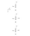
- Figure 5 is a schematic diagram showing an example of the arrangement of openings 112 in the plate-shaped fin 11.
- Figure 5(a) shows an example in which one opening 112 is arranged perpendicular to the direction of the outside air flow, in other words, the longitudinal direction of the opening 112 is aligned with the vertical direction or the direction of gravity.
- FIG. 5(b) shows an example in which the openings 112 are arranged at an angle to the direction of the outside air flow.
- the number of openings 112 is not limited to one, and may be multiple.
- Figure 5(c) shows an example of an arrangement of multiple openings 112.
- the multiple openings 112 are arranged side by side in the direction of the outside air flow.
- the multiple openings 112 may be arranged parallel to each other or at an angle.
- the heat exchanger 1 according to this embodiment has the above-mentioned configuration. The effects obtained by this embodiment will be described below.
- Figure 6 is a schematic diagram showing the drainage from the heat exchanger 1, particularly the water storage area R.
- Figure 6(a) shows the case where the openings 112 according to this embodiment are formed in a louvered shape
- Figure 6(b) shows the case where the openings 112 are not formed, i.e., the surface of the water storage area R is formed by a continuous single plane.
- Heat transfer tubes 12 which have a flat cross-sectional shape, have excellent heat transfer performance and are advantageous in achieving high heat exchange efficiency, but in reality, drainage does not proceed smoothly due to their cross-sectional shape.
- the water W1, W2 flows along the upper surface of the heat transfer tube 12 toward the leading edge 12f and the trailing edge 12r, that is, toward the windward and leeward sides, and when the water flowing toward the leeward side reaches the trailing edge 12r of the heat transfer tube 12, it leaves the heat transfer tube 12 and is carried away by the current of the outside air.
- water flowing to the windward side passes over the front edge 12f of the first heat transfer tube 12u, travels along the underside of the first heat transfer tube 12u, and flows around to the bottom of the first heat transfer tube 12u, and enters the water storage area R directly below (arrows a31, a32).
- the water that has entered then merges with water W2 present in the water storage area R to form a larger water mass, which then flows out of the water storage area R (arrow a4).
- the water that has come over the front edge 12f of the first heat transfer tube 12u enters the water storage area R, which causes a problem that smooth drainage from the water storage area R is hindered.
- the opening 112 is formed along the leading edge of the water storage region R, in other words, along the second imaginary line VL2 connecting the leading edges 12f of the heat transfer tubes 12 arranged vertically.
- surface tension acts effectively on the periphery of the opening 112, particularly on the upwind edge close to the leading edge 12f (hereinafter sometimes referred to as the "long side of the opening"), of the water that has arrived over the leading edge 12f of the first heat transfer tube 12u, which is the upper heat transfer tube 12, and this surface tension prevents the water from moving across the opening 112 in the direction of the outside air flow, so that the water flows downward along the opening 112 and moves downward toward the second heat transfer tube 12l, which is the lower heat transfer tube 12 (arrow a5).
- the opening 112 prevents the water that has come over the front edge 12f of the upper heat transfer tube 12 (first heat transfer tube 12u) from entering the water storage region R, and promotes the flow of water outside the water storage region R, i.e., outside the second imaginary line VL2 relative to the water storage region R. Therefore, by employing a heat transfer tube 12 with a flat cross-sectional shape, it is possible to provide a heat exchanger 1 that has good drainage while achieving high heat exchange efficiency.
- a first imaginary plane whose upper and lower edges are determined by a first imaginary line VL1 that is determined horizontally (Z direction) at a position midway between the underside of the upper heat transfer tube 12 (first heat transfer tube 12u) and a pair of heat transfer tubes 12 that are lined up vertically; a second imaginary plane that extends from the front edge 12f toward the rear edge 12r on the opposite side, with a second imaginary line VL2 that is determined vertically (Y direction) to connect the front edge portions 12f of the pair of heat transfer tubes 12 as its edge; and a third imaginary plane that extends in a direction approaching the front edge portion 12f, with a third imaginary line VL3 that is determined vertically to connect the middle portions of the pair of heat transfer tubes 12 in the short direction (Z direction). It is possible to favorably promote improvement in drainage.
- the openings 112 hinder the transfer of heat in the plate-shaped fins 11, making it possible to suppress the adverse effect that the formation of the openings 112 has on the heat transfer characteristics of the plate-shaped fins 11.
- the opening 112 formed in a louver shape as shown in FIG. 4(c) is used, but it is not limited to this.
- the opening 112 may be one in which a through-hole 112a is simply formed as shown in FIG. 4(a), or one in which a protrusion 112b in a slit shape or other shape is provided to cover the through-hole 112a as shown in FIG. 4(b).
- This makes it possible to improve the heat transfer characteristics of the plate-like fin 11 while also achieving good drainage properties.
- FIG. 4(a) it is possible to suppress ventilation resistance and promote a smooth flow of outside air.
- the openings 112 may be formed not only so that their longitudinal direction is aligned with the vertical direction or the direction of gravity as shown in FIG. 5(a), but also so that they are formed at an angle as shown in FIG. 5(b), which allows the water flowing along the openings 112 to have a flow velocity component in a direction away from the water storage region R, and more actively promotes drainage from the water storage region R. Furthermore, as shown in FIG. 5(c), by arranging multiple openings 112 in the short direction of the heat transfer tube 12, which in this embodiment is the Z direction which is the flow direction of the outside air, if water has entered the water storage region R beyond one opening 112, the other opening 112 can suppress further intrusion of the water and promote drainage from the water storage region R.
- the opening 112 is preferably formed with an appropriate distance Dga from the second virtual line VL2, which allows the surface tension acting on the water at the periphery of the opening 112, particularly at the long side close to the front edge 12f, to be optimized.
- the distance Dga is preferably 1 mm or more and 4 mm or less.
- the opening 112 is formed with an appropriate distance Dgb from the underside 12b of the upper heat transfer tube 12, which prevents water generated near the underside 12b of the upper heat transfer tube 12 from entering the opening 112 and promotes the movement of water flowing along the periphery of the opening 112, particularly along the long side close to the front edge 12f.
- the distance Db is preferably 0.5 mm or more and 2 mm or less.
- Fig. 7 is a schematic diagram showing an example of another embodiment of the present invention in which the plate fin 11 is formed with the concave and convex portions 113 in addition to the openings 112.
- the uneven portion 113 is arranged in the flow direction of the outside air, i.e., in the short direction of the heat transfer tube 12, and forms a plurality of convex rib portions 113a, 113b extending in a direction perpendicular to the flow direction of the outside air.
- the convex rib portion formed by the uneven portion 113 includes a first convex rib portion 113a that is formed below the opening 112, i.e., between the upper surface 12t of the lower heat transfer tube 12 and the first imaginary line VL1 and is relatively short in the vertical direction, and a second convex rib portion 113b that is longer in the vertical direction than the first convex rib portion 113a and is formed on the opposite side of the second imaginary line VL2 from the opening 112, in this embodiment, between the second imaginary line VL2 and the third imaginary line VL3 and on the leeward side of the opening 112.
- the uneven portion 113 forms concave ridges extending in the vertical direction between adjacent first convex ridges 113a and 113a, and between the first convex ridges 113a and the second convex ridges 113b.
- headers 13 and 14 are shown as cylindrical headers, but the headers 13 and 14 are not limited to this and may be, for example, stacked headers formed by stacking plate-like plates.
- the plate-like fin 11 is not limited to a shape in which the portions other than the openings 112 and the uneven portions 113 are flat, and may have a shape that has a step portion extending in the Y direction, which is the direction in which the heat transfer tubes 12 are arranged, in the portion outside the water storage region R, which in this embodiment is the region upwind of the second virtual line VL2.
- the direction in which the outside air flows between the plate-like fins 11 is not limited to the Z direction, but may be the reverse Z direction.
- the outside air passes through the water storage area R from the rear edge 12r to the front edge 12f of the heat transfer tube 12.
- the second imaginary line VL2 defines the leeward edge of the second imaginary surface
- the third imaginary line VL3 defines the windward edge of the third imaginary surface.
- the direction in which the through-hole 112a is opened is not limited to the direction toward the front edge 12f of the heat transfer tube 12, but may be the direction toward the rear edge 12r.
- the louver-shaped opening 112 may be shaped so that the through-hole 112a is open toward the rear edge 12r of the heat transfer tube 12, while being closed toward the front edge 12f.
- C...refrigeration cycle device 1...heat exchanger (outdoor heat exchanger), 1a...casing, 1'...outdoor fan, 2...compressor, 2a...compressor body, 2b...accumulator, 3...four-way valve, 4...expansion valve, 5...indoor heat exchanger, 5'...indoor fan, 6, 6a-6f...refrigerant piping, 11...plate-shaped fins, 111...collar, 12...heat transfer tube, 121...internal passage, 13, 14...header, 15...gas side joint, 16...liquid side joint, X...thickness direction of plate-shaped fins, extension direction of heat transfer tube, Y...direction in which heat transfer tubes are arranged, Z...direction of flow of outside air, R...water storage area, VL1...first virtual line, VL2...second virtual line, VL3...third virtual line.
Landscapes
- Engineering & Computer Science (AREA)
- Physics & Mathematics (AREA)
- Thermal Sciences (AREA)
- Mechanical Engineering (AREA)
- General Engineering & Computer Science (AREA)
- Geometry (AREA)
- Heat-Exchange Devices With Radiators And Conduit Assemblies (AREA)
Priority Applications (4)
| Application Number | Priority Date | Filing Date | Title |
|---|---|---|---|
| CN202380095419.7A CN120826580A (zh) | 2023-03-28 | 2023-03-28 | 热交换器 |
| JP2025509317A JPWO2024201694A1 (https=) | 2023-03-28 | 2023-03-28 | |
| EP23930334.0A EP4692711A1 (en) | 2023-03-28 | 2023-03-28 | Heat exchanger |
| PCT/JP2023/012423 WO2024201694A1 (ja) | 2023-03-28 | 2023-03-28 | 熱交換器 |
Applications Claiming Priority (1)
| Application Number | Priority Date | Filing Date | Title |
|---|---|---|---|
| PCT/JP2023/012423 WO2024201694A1 (ja) | 2023-03-28 | 2023-03-28 | 熱交換器 |
Publications (1)
| Publication Number | Publication Date |
|---|---|
| WO2024201694A1 true WO2024201694A1 (ja) | 2024-10-03 |
Family
ID=92903546
Family Applications (1)
| Application Number | Title | Priority Date | Filing Date |
|---|---|---|---|
| PCT/JP2023/012423 Ceased WO2024201694A1 (ja) | 2023-03-28 | 2023-03-28 | 熱交換器 |
Country Status (4)
| Country | Link |
|---|---|
| EP (1) | EP4692711A1 (https=) |
| JP (1) | JPWO2024201694A1 (https=) |
| CN (1) | CN120826580A (https=) |
| WO (1) | WO2024201694A1 (https=) |
Citations (5)
| Publication number | Priority date | Publication date | Assignee | Title |
|---|---|---|---|---|
| JP2014156990A (ja) * | 2013-02-18 | 2014-08-28 | Mitsubishi Electric Corp | 空気調和機の熱交換器 |
| WO2016194088A1 (ja) * | 2015-05-29 | 2016-12-08 | 三菱電機株式会社 | 熱交換器及び冷凍サイクル装置 |
| WO2017130399A1 (ja) * | 2016-01-29 | 2017-08-03 | 三菱電機株式会社 | 冷凍サイクル装置及び扁平管熱交換器 |
| WO2017221303A1 (ja) * | 2016-06-20 | 2017-12-28 | 三菱電機株式会社 | 熱交換器およびこの熱交換器を備えたヒートポンプ装置 |
| WO2019239519A1 (ja) * | 2018-06-13 | 2019-12-19 | 三菱電機株式会社 | 熱交換器、熱交換器ユニット、及び冷凍サイクル装置 |
-
2023
- 2023-03-28 JP JP2025509317A patent/JPWO2024201694A1/ja active Pending
- 2023-03-28 EP EP23930334.0A patent/EP4692711A1/en active Pending
- 2023-03-28 CN CN202380095419.7A patent/CN120826580A/zh active Pending
- 2023-03-28 WO PCT/JP2023/012423 patent/WO2024201694A1/ja not_active Ceased
Patent Citations (6)
| Publication number | Priority date | Publication date | Assignee | Title |
|---|---|---|---|---|
| JP2014156990A (ja) * | 2013-02-18 | 2014-08-28 | Mitsubishi Electric Corp | 空気調和機の熱交換器 |
| WO2016194088A1 (ja) * | 2015-05-29 | 2016-12-08 | 三菱電機株式会社 | 熱交換器及び冷凍サイクル装置 |
| JP6710205B2 (ja) | 2015-05-29 | 2020-06-17 | 三菱電機株式会社 | 熱交換器及び冷凍サイクル装置 |
| WO2017130399A1 (ja) * | 2016-01-29 | 2017-08-03 | 三菱電機株式会社 | 冷凍サイクル装置及び扁平管熱交換器 |
| WO2017221303A1 (ja) * | 2016-06-20 | 2017-12-28 | 三菱電機株式会社 | 熱交換器およびこの熱交換器を備えたヒートポンプ装置 |
| WO2019239519A1 (ja) * | 2018-06-13 | 2019-12-19 | 三菱電機株式会社 | 熱交換器、熱交換器ユニット、及び冷凍サイクル装置 |
Non-Patent Citations (1)
| Title |
|---|
| See also references of EP4692711A1 |
Also Published As
| Publication number | Publication date |
|---|---|
| EP4692711A1 (en) | 2026-02-11 |
| JPWO2024201694A1 (https=) | 2024-10-03 |
| CN120826580A (zh) | 2025-10-21 |
Similar Documents
| Publication | Publication Date | Title |
|---|---|---|
| JP4122608B2 (ja) | 冷媒蒸発器 | |
| CN103314267B (zh) | 热交换器及空调机 | |
| CN103314269B (zh) | 热交换器及空调机 | |
| JP6710205B2 (ja) | 熱交換器及び冷凍サイクル装置 | |
| CN105937816B (zh) | 翅片管式热交换器以及具备它的制冷循环装置 | |
| US10557652B2 (en) | Heat exchanger and air conditioner | |
| CN107407534A (zh) | 热交换器及空气调节机 | |
| JP2007232246A (ja) | 熱交換器 | |
| CN103299150A (zh) | 热交换器和空调机 | |
| JP6701371B2 (ja) | 熱交換器及び冷凍サイクル装置 | |
| CN211290633U (zh) | 热交换器以及使用该热交换器的制冷循环装置 | |
| EP3809085B1 (en) | Heat exchanger, heat exchanger unit, and refrigeration cycle apparatus | |
| JP6678413B2 (ja) | 空気調和機 | |
| JP6932262B2 (ja) | 熱交換器、熱交換器ユニット、及び冷凍サイクル装置 | |
| WO2024201694A1 (ja) | 熱交換器 | |
| WO2024053236A1 (ja) | 熱交換器 | |
| JP2015031484A (ja) | 熱交換器及びそれを備えた空気調和機 | |
| WO2017154175A1 (ja) | 熱交換器 | |
| WO2025238874A1 (ja) | 熱交換器 | |
| CN117769636A (zh) | 热交换器 | |
| WO2025069304A1 (ja) | 熱交換器 | |
| JP7596606B1 (ja) | 熱交換器及び空気調和装置 | |
| WO2022224350A1 (ja) | 熱交換器 | |
| JP2015031483A (ja) | 熱交換器及びそれを備えた空気調和機 | |
| WO2025079135A1 (ja) | 熱交換器、冷凍サイクル装置および冷凍サイクルシステム |
Legal Events
| Date | Code | Title | Description |
|---|---|---|---|
| 121 | Ep: the epo has been informed by wipo that ep was designated in this application |
Ref document number: 23930334 Country of ref document: EP Kind code of ref document: A1 |
|
| ENP | Entry into the national phase |
Ref document number: 2025509317 Country of ref document: JP Kind code of ref document: A |
|
| WWE | Wipo information: entry into national phase |
Ref document number: 2025509317 Country of ref document: JP |
|
| WWE | Wipo information: entry into national phase |
Ref document number: 202380095419.7 Country of ref document: CN |
|
| WWP | Wipo information: published in national office |
Ref document number: 202380095419.7 Country of ref document: CN |
|
| WWE | Wipo information: entry into national phase |
Ref document number: 2023930334 Country of ref document: EP |
|
| NENP | Non-entry into the national phase |
Ref country code: DE |
|
| ENP | Entry into the national phase |
Ref document number: 2023930334 Country of ref document: EP Effective date: 20251028 |
|
| ENP | Entry into the national phase |
Ref document number: 2023930334 Country of ref document: EP Effective date: 20251028 |
|
| ENP | Entry into the national phase |
Ref document number: 2023930334 Country of ref document: EP Effective date: 20251028 |
|
| ENP | Entry into the national phase |
Ref document number: 2023930334 Country of ref document: EP Effective date: 20251028 |
|
| ENP | Entry into the national phase |
Ref document number: 2023930334 Country of ref document: EP Effective date: 20251028 |
|
| ENP | Entry into the national phase |
Ref document number: 2023930334 Country of ref document: EP Effective date: 20251028 |
|
| ENP | Entry into the national phase |
Ref document number: 2023930334 Country of ref document: EP Effective date: 20251028 |
|
| ENP | Entry into the national phase |
Ref document number: 2023930334 Country of ref document: EP Effective date: 20251028 |
|
| WWP | Wipo information: published in national office |
Ref document number: 2023930334 Country of ref document: EP |