WO2024201688A1 - 基板取り出し方法、及び基板移送システム - Google Patents
基板取り出し方法、及び基板移送システム Download PDFInfo
- Publication number
- WO2024201688A1 WO2024201688A1 PCT/JP2023/012398 JP2023012398W WO2024201688A1 WO 2024201688 A1 WO2024201688 A1 WO 2024201688A1 JP 2023012398 W JP2023012398 W JP 2023012398W WO 2024201688 A1 WO2024201688 A1 WO 2024201688A1
- Authority
- WO
- WIPO (PCT)
- Prior art keywords
- substrate
- robot hand
- edge
- detection unit
- detection
- Prior art date
- Legal status (The legal status is an assumption and is not a legal conclusion. Google has not performed a legal analysis and makes no representation as to the accuracy of the status listed.)
- Ceased
Links
Images












Classifications
-
- H—ELECTRICITY
- H10—SEMICONDUCTOR DEVICES; ELECTRIC SOLID-STATE DEVICES NOT OTHERWISE PROVIDED FOR
- H10P—GENERIC PROCESSES OR APPARATUS FOR THE MANUFACTURE OR TREATMENT OF DEVICES COVERED BY CLASS H10
- H10P72/00—Handling or holding of wafers, substrates or devices during manufacture or treatment thereof
- H10P72/30—Handling or holding of wafers, substrates or devices during manufacture or treatment thereof for conveying, e.g. between different workstations
- H10P72/34—Handling or holding of wafers, substrates or devices during manufacture or treatment thereof for conveying, e.g. between different workstations the wafers being stored in a carrier, involving loading and unloading
- H10P72/3402—Mechanical parts of transfer devices
-
- B—PERFORMING OPERATIONS; TRANSPORTING
- B25—HAND TOOLS; PORTABLE POWER-DRIVEN TOOLS; MANIPULATORS
- B25J—MANIPULATORS; CHAMBERS PROVIDED WITH MANIPULATION DEVICES
- B25J9/00—Program-controlled manipulators
- B25J9/10—Program-controlled manipulators characterised by positioning means for manipulator elements
-
- H—ELECTRICITY
- H10—SEMICONDUCTOR DEVICES; ELECTRIC SOLID-STATE DEVICES NOT OTHERWISE PROVIDED FOR
- H10P—GENERIC PROCESSES OR APPARATUS FOR THE MANUFACTURE OR TREATMENT OF DEVICES COVERED BY CLASS H10
- H10P72/00—Handling or holding of wafers, substrates or devices during manufacture or treatment thereof
- H10P72/06—Apparatus for monitoring, sorting, marking, testing or measuring
- H10P72/0606—Position monitoring, e.g. misposition detection or presence detection
- H10P72/0608—Position monitoring, e.g. misposition detection or presence detection of substrates stored in a container, a magazine, a carrier, a boat or the like
-
- H—ELECTRICITY
- H10—SEMICONDUCTOR DEVICES; ELECTRIC SOLID-STATE DEVICES NOT OTHERWISE PROVIDED FOR
- H10P—GENERIC PROCESSES OR APPARATUS FOR THE MANUFACTURE OR TREATMENT OF DEVICES COVERED BY CLASS H10
- H10P72/00—Handling or holding of wafers, substrates or devices during manufacture or treatment thereof
- H10P72/10—Handling or holding of wafers, substrates or devices during manufacture or treatment thereof using carriers specially adapted therefor, e.g. front opening unified pods [FOUP]
- H10P72/19—Handling or holding of wafers, substrates or devices during manufacture or treatment thereof using carriers specially adapted therefor, e.g. front opening unified pods [FOUP] closed carriers
- H10P72/1921—Handling or holding of wafers, substrates or devices during manufacture or treatment thereof using carriers specially adapted therefor, e.g. front opening unified pods [FOUP] closed carriers characterised by substrate supports
-
- H—ELECTRICITY
- H10—SEMICONDUCTOR DEVICES; ELECTRIC SOLID-STATE DEVICES NOT OTHERWISE PROVIDED FOR
- H10P—GENERIC PROCESSES OR APPARATUS FOR THE MANUFACTURE OR TREATMENT OF DEVICES COVERED BY CLASS H10
- H10P72/00—Handling or holding of wafers, substrates or devices during manufacture or treatment thereof
- H10P72/30—Handling or holding of wafers, substrates or devices during manufacture or treatment thereof for conveying, e.g. between different workstations
-
- H—ELECTRICITY
- H10—SEMICONDUCTOR DEVICES; ELECTRIC SOLID-STATE DEVICES NOT OTHERWISE PROVIDED FOR
- H10P—GENERIC PROCESSES OR APPARATUS FOR THE MANUFACTURE OR TREATMENT OF DEVICES COVERED BY CLASS H10
- H10P72/00—Handling or holding of wafers, substrates or devices during manufacture or treatment thereof
- H10P72/30—Handling or holding of wafers, substrates or devices during manufacture or treatment thereof for conveying, e.g. between different workstations
- H10P72/33—Handling or holding of wafers, substrates or devices during manufacture or treatment thereof for conveying, e.g. between different workstations into and out of processing chamber
- H10P72/3302—Mechanical parts of transfer devices
-
- H—ELECTRICITY
- H10—SEMICONDUCTOR DEVICES; ELECTRIC SOLID-STATE DEVICES NOT OTHERWISE PROVIDED FOR
- H10P—GENERIC PROCESSES OR APPARATUS FOR THE MANUFACTURE OR TREATMENT OF DEVICES COVERED BY CLASS H10
- H10P72/00—Handling or holding of wafers, substrates or devices during manufacture or treatment thereof
- H10P72/30—Handling or holding of wafers, substrates or devices during manufacture or treatment thereof for conveying, e.g. between different workstations
- H10P72/34—Handling or holding of wafers, substrates or devices during manufacture or treatment thereof for conveying, e.g. between different workstations the wafers being stored in a carrier, involving loading and unloading
- H10P72/3411—Handling or holding of wafers, substrates or devices during manufacture or treatment thereof for conveying, e.g. between different workstations the wafers being stored in a carrier, involving loading and unloading involving loading and unloading of wafers
Definitions
- the present invention relates to a substrate removal method and a substrate transfer system.
- a technique for using an industrial substrate transport robot installed in a substrate transport device to remove substrates (e.g., wafers, glass substrates, etc.) from a container that contains the substrates, transport them to various processing equipment, and process the transported substrates.
- the substrate transport robot is equipped with a robot arm and a robot hand attached to the tip of the robot arm, and transports the substrate while holding it with the robot hand.
- various techniques have been disclosed for transporting substrates using a substrate transport robot, in which a robot hand is inserted into a container that contains substrates, supports the substrate from below, and thereby lifts the substrate from the placement section inside the container, and removes the substrate from the container as the robot arm moves.
- PLP panel level packaging
- a FOUP Front Opening Unified Pod
- substrate placement areas hereinafter referred to as slots
- a substrate is placed on each slot.
- the FOUP may not be configured and positioned so that there is horizontal space (front to back and left to right) when the substrate is placed.
- the substrate in the FOUP may be placed at an angle in the horizontal plane relative to the FOUP (when the edges E1 and E2 of the substrate are not parallel to the inner wall surface of the storage container H. See Figure 7).
- contactable areas there are areas on the underside of the substrate that the substrate support part of the robot hand may contact
- non-contactable areas areas that must not be contacted
- the substrate is stored in the storage container in an inclined state on the horizontal plane, the position of the contactable areas will also be different. Therefore, when the robot hand supports a substrate that is inclined in a fixed position (fixed support position), the substrate support part of the robot hand may come into contact with the non-contactable areas of the substrate, which may cause damage or particle adhesion to the non-contactable areas.
- the present invention provides a substrate removal method that can improve the control stability when removing a substrate, and a substrate transfer system that applies the substrate removal method.
- a substrate removal method for removing a substrate placed at a predetermined position in a storage container having an opening on one side in a first direction by a robot hand provided on a substrate transport robot, the robot hand comprising a hand base, an extension portion extending from the hand base to one side in a second direction, a substrate detection portion provided on the extension portion, and a substrate support portion provided on the extension portion, and is controlled by a control device, the substrate removal method comprising a first movement step of moving the robot hand to the other side in the first direction and inserting the extension portion into the storage container through the opening, and detecting at least one linear edge of the substrate due to a change in the detection status of the substrate by the substrate detection portion during the first movement step.
- the method includes a first detection step of identifying the position of the extension part of the robot hand, a first stopping step of stopping the movement of the robot hand toward the other side of the first direction, a calculation step of calculating the inclination of the substrate with respect to the robot hand based on the position of the edge part of the substrate detected in the first detection step, a correction step of correcting the position and attitude of the robot hand based on the inclination of the substrate calculated in the calculation step, a substrate support step in which the substrate support part supports the substrate, and a removal step in which the robot hand supporting the substrate is moved to one side in the first direction and the substrate is removed from the storage container, and the correction step is performed while the extension part of the robot hand is positioned inside the storage container.
- the present invention provides a substrate transfer system comprising a substrate transport robot including a robot hand for supporting a substrate and a moving mechanism for movably holding the robot hand, a substrate transport module having the substrate transport robot installed therein, and a control device for controlling the substrate transport robot, wherein the robot hand of the substrate transport robot includes a hand base, an extension extending from the hand base to one side in a second direction, a substrate detection unit provided on the extension unit, and a substrate support unit provided on the extension unit, and is controlled by the control device, and the control device controls the substrate transport robot by the substrate removal method to remove a substrate placed at a predetermined position in a storage container using the robot hand.
- the substrate removal method and the substrate transfer system to which the substrate removal method is applied can correct the position and orientation of the robot hand based on the inclination in the horizontal plane of the substrate stored in the storage container, support the substrate, and then remove it.
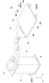
- FIG. 1 illustrates a perspective view of a substrate transfer system in accordance with one embodiment of the present invention
- 2 is a perspective explanatory view of a substrate transport robot provided in the substrate transfer system shown in FIG. 1 .
- 2 is an explanatory view of a container placed on a load port provided in the substrate transfer system shown in FIG. 1 .
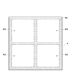
- 3 is a plan view illustrating a contactable area and a non-contactable area of the substrate shown in FIG. 2 .
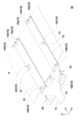
- FIG. 2 is a perspective explanatory view of a robot hand attached to the substrate transport robot shown in FIG. 1 .
- 6 is a top view illustrating the robot hand shown in FIG. 5 when removing a substrate to be stored in a container.
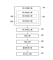
- FIG. 6 is a flowchart of a substrate removal method to which the robot hand shown in FIG. 5 is applied.
- 8 is a flowchart of a correction process of the substrate removal method shown in FIG. 7 .
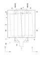
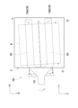
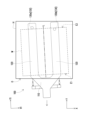
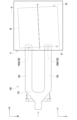
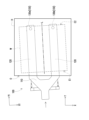
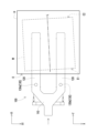
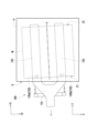
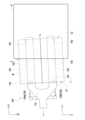
- ⁇ 9A to 9C are top view explanatory diagrams of the relative positions of the container and the substrate of the robot hand corresponding to each step of the substrate removal method shown in FIGS. 7 and 8 in the first embodiment.
- 13 is a top view illustrating the relative positions of the container and the substrate of the robot hand corresponding to a substrate supporting step of the substrate removal method in the modified example of the first embodiment.
- ⁇ 9A to 9F are top view explanatory diagrams of the relative positions of the container and the substrate of the robot hand corresponding to each step of the substrate removal method in another modified example of the first embodiment shown in FIGS. 9A to 9F.
- ⁇ 9A to 9C are top view explanatory diagrams of the relative positions of the container and the substrate of the robot hand corresponding to each step of the substrate removal method shown in FIGS. 7 and 8 in the second embodiment.
- the positions and operations of the substrate transfer system 20, the substrate transport robot 30, and the storage container H for storing the substrate W will be described based on the left-right direction X, the front-back direction Y, and the up-down direction Z of the spatial coordinate system XYZ, and the position and operation of the robot hand 100 will be described based on the left-right direction X1, the front-back direction Y1, and the up-down direction Z1 of the spatial coordinate system XYZ.
- the left-right direction X1, the front-back direction Y1, and the up-down direction Z1 of the robot hand 100 may coincide with the left-right direction X, the front-back direction Y, and the up-down direction Z depending on the posture of the robot hand 100, but may be inclined with respect to the left-right direction X, the front-back direction Y, and the up-down direction Z.
- this is merely one example of the present invention and the present invention is not limited to this example.
- the substrate transfer system 20 of this embodiment includes the substrate transfer robot 30 equipped with the robot hand 100, a substrate transfer module 22 having the substrate transfer robot 30 installed therein, at least one load port C1 arranged on one side (e.g., the front side) of the substrate transfer module 22, at least one processing device C2 arranged on the other side (e.g., the rear side) of the substrate transfer module 22, and a control unit 24 that controls the substrate transfer robot 30.
- the substrate transport module 22 is, for example, an EFEM (Equipment Front End Module)
- the load port C1 is a device for placing a storage container H (e.g., a FOUP) that contains a substrate W and opening and closing the door of the storage container H
- the processing device C2 is a device for processing the substrate W.
- the type of processing device C2 can be selected according to the content of the process for processing the substrate W (e.g., a process required for the semiconductor manufacturing process, such as ion implantation or etching).
- a load lock chamber may be further installed between the substrate transport module 22 and the processing device C2.
- the present invention is not limited to this.
- the substrate transport module 22 includes a housing 22a, a substrate transport robot 30 provided inside the housing 22a, a moving body 22b that moves the substrate transport robot 30, and a guide structure 22c for guiding the movement of the substrate transport robot 30.
- the housing 22a is installed between the load port C1 and the processing device C2 (or the load lock chamber) and connects the load port C1 and the processing device C2 (or the load lock chamber).
- members such as the moving body 22b, the guide structure 22c, and the substrate transport robot 30 are installed inside the housing 22a.
- the moving body 22b is attached to a guide structure 22c (e.g., a slide rail structure, a conveyor drive device, etc.) for guiding the movement in the left-right direction X, and is installed so as to be freely movable within the housing 22a by the guide structure 22c.
- the substrate transport robot 30 is attached to the moving body 22b, and is movable (slidable) in the left-right direction X by the moving body 22b and the guide structure 22c. This allows the substrate transport robot 30 to freely access both the load port C1 and the processing device C2 (or the load lock chamber).
- the substrate transport robot 30 also includes a robot hand 100 for supporting the substrate W, and a moving mechanism (including, for example, an arm unit 32, a main body unit 34, and an arm drive unit 36) that holds the robot hand 100 movably.
- the main body unit 34 is attached to the aforementioned moving body 22b, and moves in the left-right direction X by the moving body 22b and the guide structure 22c.
- the arm unit 32 is attached to the upper end of the main body unit 34 so as to be extendable and rotatable within a horizontal plane (a virtual horizontal plane formed by the left-right direction X and the front-back direction Y) relative to the main body unit 34, and also to be able to move up and down in the up-down direction Z.
- the arm drive unit 36 is, for example, a motor or transmission mechanism built into the main body unit 34, and applies a driving force to the arm unit 32, but may be attached to the outside of the main body unit 34.
- the robot hand 100 is attached to the tip of the arm unit 32. Therefore, the substrate transport robot 30 can not only move in the left-right direction X by the moving body 22b and the guide structure 22c via the main body 34, but also drive the arm 32 via the arm drive unit 36, allowing the robot hand 100 to move freely (up and down, rotate, back and forth).
- the substrate W is, for example, a glass substrate used in PLP, and is stored in a storage container H for storing the substrate W.
- the FOUP as the storage container H has, for example, multiple stages (for example, 12 stages) of slots S (shown in FIG. 3), and multiple substrates W can be stored by placing a substrate W in each of the multiple stages of slots S.
- the slots S are plate members that protrude from the inner wall of the storage container H and support both ends of the substrate W in the left-right direction X. Note that the number of substrates W stored in the storage container H can be appropriately selected, and the present invention is not limited to this.
- the FOUP as the storage container H is placed on the load port C1.
- the substrate transport robot 30 moves the arm member 32 via the arm drive unit 36, and moves the robot hand 100 below the corresponding substrate W. Thereafter, the substrate W is supported by the substrate support portion 140 of the robot hand 100, and the robot hand 100 is moved to the outside of the storage container H to remove the substrate W from the storage container H and load it into the housing 22a. Therefore, the control device 24 of the substrate transfer module 20 can control the substrate transfer robot 30 to remove the substrate W placed at a predetermined position in the storage container H by the robot hand 100 using a substrate removal method described below.
- the movable body 22b and guide structure 22c provided in the housing 22a of the substrate transfer module 22 may be omitted, and the substrate transfer robot 30 may be fixed to the housing 110 (for example, the main body 34 of the substrate transfer robot 30 may be fixed to the lower part of the housing 110).
- the substrate transfer robot 30 itself is immovable relative to the substrate transfer module 22, but the substrate W can be transferred between the load port C1 and the processing device C2 by extending and lowering the arm 32 having multiple joints and rotating around the main body 34.
- the specific structures and positional relationships of the substrate transfer module 22, the load port C1, and the processing device C2 of the substrate transfer system 20, or the specific structure of the substrate transfer robot 30, may be adjusted as necessary. The present invention is not limited to this.
- FIG. 4 is a view of the substrate W viewed from below (for example, a view of the substrate W viewed from the side opposite to the side indicated by the arrow in the vertical direction Z), and the substrate W is a rectangular plate material having a thickness.
- the bottom surface of the substrate W has a contactable region R1 with which the substrate support part 140 of the robot hand 100 in FIG. 2 or the slot S of the storage container H in FIG. 3 may come into contact, and a non-contactable region R2 with which contact is prohibited.
- four non-contactable regions R2 are evenly provided on the bottom surface of the substrate W, and a contactable region R1 (shaded area in FIG.
- each non-contactable region R2 is provided so as to cover the periphery of each non-contactable region R2.
- the number, dimensions, relative positions, etc. of the contactable regions R1 and the non-contactable regions R2 may differ depending on the type and size of the substrate W. The present invention is not limited to this.
- the robot hand 100 can be used to remove the substrate W placed at a predetermined position in a storage container H having an opening O on one side in a first direction (here, the side opposite to the side indicated by the arrow in the forward/backward direction Y).
- the robot hand 100 of the substrate transport robot 30 includes a hand base 110, an extension part 120 extending from the hand base 110 to one side in a second direction (here, the side indicated by the arrow in the forward/backward direction Y1), a substrate detection part 130 provided on the extension part 120, and a substrate support part 140 provided on the extension part 120, and is controlled by a control device 24. That is, the substrate removal method described below involves controlling the robot hand 100 of the substrate transport robot 30 by the control device 24, and removing the substrate W stored in the storage container H from the opening O by the robot hand 100 provided on the substrate transport robot 30.
- the robot hand 100 is attached to, for example, the arm portion 32 of the substrate transport robot 30, and transports the substrate W while holding it in accordance with the movement of the arm portion 32.
- the hand base portion 110 is connected to the arm portion 32 (shown in FIG. 2), and the extension portion 120 extends from the hand base portion 110 to one side in the second direction (the side indicated by the arrow in the front-rear direction Y1).
- two extension portions 120 spaced apart in a third direction (here, the left-right direction X1) perpendicular to the second direction extend from the hand base portion 110, and the robot hand 100 is configured in an approximately Y-shape.
- the substrate support portion 140 is installed on the extension portion 120 and can support the substrate W from the underside of the substrate W.
- a plurality of substrate support portions 140 are installed on the extension portion 120.
- the substrate support portion 140 includes a first substrate support portion 140A, a second substrate support portion 140B, and a third substrate support portion 140C.
- the first substrate support portion 140A is installed at the tip side, which is one side of the extension portion 120 in the second direction (the side indicated by the arrow in the front-rear direction Y1).
- the second substrate support portion 140B is installed at the base end side, which is the other side of the extension portion 120 in the second direction (here, the side opposite to the side indicated by the arrow in the front-rear direction Y1).
- the third substrate support portion 140C is installed between the first substrate support portion 140A and the second substrate support portion 140B in the second direction (front-rear direction Y1), which is the extension direction of the extension portion 120.
- the two extensions 120 are each provided with a first substrate support portion 140A, a second substrate support portion 140B, and a third substrate support portion 140C.
- the lower surface of the substrate W has a contactable region R1 and a non-contactable region R2, as shown in FIG. 4.
- the substrate support portions 140 are arranged so that when the robot hand 100 and the substrate W are in an appropriate positional relationship (for example, when the relative position and posture of the robot hand 100 with respect to the substrate W are in a predetermined position and posture), all the substrate support portions 140 come into contact only with the contactable region R1 of the substrate W in a substrate supporting process after a correction process described below.
- the robot hand 100 can be provided with a regulating section 150 for regulating the position of the substrate W supported by the extension section 120 as necessary.
- a first regulating section 150A is provided at the tip side of the extension section 120, which is one side in the second direction (the side indicated by the arrow in the front-rear direction Y1)
- a second regulating section 150B is provided at the base side of the extension section 120, which is the other side in the second direction (the side opposite to the side indicated by the arrow in the front-rear direction Y1).
- first regulating section 150A to abut against the end face of the substrate W on the other side in the first direction (the side indicated by the arrow in the front-rear direction Y), and the second regulating section 150B to abut against the end face of the substrate W on one side in the first direction (here, the side opposite to the side indicated by the arrow in the front-rear direction Y).
- These substrate support parts 140 and regulating parts 150 may be installed on the upper surface 122 of the extension part 120 so as to be retractable or deployable (as shown in FIG. 5), and may be driven by a driving part 160 provided on the hand base part 110 or the extension part 120.
- the driving source of the driving part 160 is provided on the hand base part 110 by a mounting plate 124.
- the number and installation positions of the substrate support parts 140, the necessity of installing the regulating parts 150 and the driving part 160, or the type and installation position of the driving part 160 may be adjusted as necessary. The present invention is not limited to this.
- the substrate detection unit 130 is provided in the extension portion 120 and detects the presence or absence of a substrate above the substrate detection unit 130.
- the substrate detection unit 130 can identify the position of the edge E of the substrate W by changing the detection state when the substrate detection unit 130 passes under the edge of the substrate W.
- a rectangular substrate is given as an example of the substrate W (e.g., approximately rectangular), but a substrate having a polygonal shape (e.g., hexagonal) or other shape may be used.
- the substrate W only needs to have at least one straight edge E. As shown in FIG.
- the substrate W when placed on the storage container H, has an edge E1 that corresponds to one side of the first direction of the storage container H (the side opposite to the side indicated by the arrow in the forward/backward direction Y) and is close to the opening O, and an edge E2 that corresponds to the other side of the first direction (the side indicated by the arrow in the forward/backward direction Y) and is away from the opening O.
- the substrate transport robot 30 moves the robot hand 100 to the other side of the first direction of the storage container H (the side indicated by the arrow in the forward/backward direction Y) and inserts the extension part 120 into the storage container H from the opening O, thereby identifying the position of either the edge part E1 or the edge part E2 by the substrate detection part 130 passing under the substrate W. Based on the identified position of either the edge part E1 or the edge part E2 of the substrate W, the tilt of the substrate W relative to the robot hand 100 is calculated, and the position and attitude of the robot hand 100 are corrected based on the calculated tilt of the substrate W.
- the substrate W is then supported by the substrate support part 140, and the robot hand 100 supporting the substrate W is moved to one side of the first direction (the side opposite to the side indicated by the arrow in the forward/backward direction Y) to remove the substrate W from the storage container H.
- the position of the substrate detection part 130 provided on the extension part 120 will be described with the following example.
- the board detection unit 130 includes a first board detection unit 130a and a second board detection unit 130b.
- the first board detection unit 130a and the second board detection unit 130b are provided on the tip side (the side of the extension unit 120 away from the hand base 110) which is one side of the two extension units 120 in the second direction (the side indicated by the arrow in the front-rear direction Y1).
- the first board detection unit 130a is provided on the extension unit 120 on the other side of the third direction (the side opposite to the side indicated by the arrow in the left-right direction X1)
- the second board detection unit 130b is provided on the extension unit 120 on one side of the third direction (here, the side indicated by the arrow in the left-right direction X1).
- the first board detection unit 130a and the second board detection unit 130b which are provided at the tip side of each of the two extension parts 120, are installed in parallel in the third direction (left-right direction X1) (installed without offset).
- FIG. 1 shows a modified example described later (shown in FIG.
- the second board detection unit 130b may be installed further away from the first board detection unit 130a on one side in the second direction (the side indicated by the arrow in the front-back direction Y1) (i.e., installed offset).
- the second board detection unit 130 may be provided on the tip side, which is one side in the second direction of the extension part 120 (the side indicated by the arrow in the front-back direction Y1).
- the board detection unit 130 includes a first board detection unit 130a and a second board detection unit 130b.
- the first board detection unit 130a and the second board detection unit 130b are provided on the base end side (the side closer to the hand base 110 of the extension unit 120) which is the other side of the second direction of the two extension units 120 (the side opposite to the side indicated by the arrow in the front-rear direction Y1).
- first board detection unit 130a and the second board detection unit 130b provided on the base end side of the two extension units 120 may be installed in parallel (installed without offset) in the third direction (left-right direction X1), or may be installed offset in the second direction in an embodiment not shown, or only one board detection unit 130 may be provided on the base end side.
- the present invention is not limited to this.
- the first direction (front-to-back direction Y) is used as a reference to define the orientation of the opening O of the storage container H, the relative position of edge E1 and edge E2 of the substrate W to be placed in the storage container H, and the movement direction when the robot hand 100 is inserted into the storage container H
- the second direction (front-to-back direction Y1) is used as a reference to define the extension direction of the extension portion 120 of the robot hand 100 and the position of the substrate detection portion 130 provided on the extension portion 120.
- the first direction (front-to-back direction Y) and the second direction (front-to-back direction Y1) are parallel.
- the robot hand 100 inserts the extension portion 120 extending to one side in the second direction (the side indicated by the arrow in the front-to-rear direction Y1) into the storage container H from the opening O toward the other side in the first direction (the side indicated by the arrow in the front-to-rear direction Y), and identifies the position of either the edge portion E1 corresponding to one side in the first direction (the side indicated by the arrow in the front-to-rear direction Y1) of the substrate W or the edge portion E2 corresponding to the other side in the first direction (the side indicated by the arrow in the front-to-rear direction Y1) by the substrate detection unit 130 provided at the tip side, which is the one side in the second direction (the side indicated by the arrow in the front-to-rear direction Y1) of the extension portion 120, or the base side, which is the other side in the second direction (the
- the second direction (front-rear direction Y1) that serves as the reference for the robot hand 100 is not limited to being parallel to the first direction (front-rear direction Y) that serves as the reference for the storage container H. It is preferable that the second direction (front-rear direction Y1) of the robot hand 100 after correction be parallel to the center line L of the substrate W in the placed state (as described below).
- the center line L is a line that is perpendicular to the edges E1 and E2 and connects the edges E1 and E2.
- the board detection unit 130 includes a first board detection unit 130a and a second board detection unit 130b that are provided at the tip side, which is one side of the second direction of the extension portion 120 (the side indicated by the arrow in the front-to-rear direction Y1), and are spaced apart in a third direction (left-to-right direction X1) perpendicular to the second direction (front-to-rear direction Y1).
- the substrate detection unit 130 includes a first substrate detection unit 130a and a second substrate detection unit 130b that are provided on the base end side, which is the other side of the second direction (the side opposite to the side indicated by the arrow in the front-rear direction Y1) of the extension unit 120, and are provided spaced apart in a third direction (left-right direction X1) perpendicular to the second direction (front-rear direction Y1).
- the substrate W has an edge E1 that corresponds to one side of the first direction of the storage container H (the side opposite to the side indicated by the arrow in the front-rear direction Y) and is located near the opening O, and an edge E2 that corresponds to the other side of the first direction (the side indicated by the arrow in the front-rear direction Y) and is located away from the opening O. Therefore, the operations of each step of the substrate removal method differ depending on the position of the substrate detection unit 130 and the position of the edge E to be detected, so the substrate removal method of the present invention will be described through the following several examples.
- the substrate removal method is a method for removing a substrate W placed at a predetermined position in a storage container H having an opening O on one side in a first direction (the side opposite to the side indicated by the arrow in the forward and backward direction Y) by a robot hand 100 provided on a substrate transport robot 30, and includes the following steps.
- First movement step S01 The robot hand 100 is moved to the other side in the first direction (the side indicated by the arrow in the forward and backward direction Y), and the extension part 120 is inserted from the opening O below the substrate W in the storage container H.
- First detection step S02 In the first movement step S01, the position of at least one linear edge part E (either edge part E1 or E2) of the substrate W is identified based on a change in the detection state of the substrate W by the substrate detection part 130.
- First stopping step S03 The movement of the robot hand 100 toward the other side in the first direction (the side indicated by the arrow in the forward and backward direction Y) is stopped.
- Calculation step S04 Calculate the inclination of the substrate W with respect to the robot hand 100 based on the position of the edge E (either edge E1 or E2) of the substrate W detected in the first detection step S02.
- Correction step S05 Correct the position and attitude of the robot hand 100 based on the position of the edge E identified in the first detection step S02 and the inclination of the substrate W calculated in the calculation step S04.
- Substrate support step S06 The substrate support part 140 abuts the bottom of the substrate W, and the robot hand 100 supports the substrate W.
- Removal step S07 The robot hand 100 supporting the substrate W is moved to one side in the first direction (the side opposite to the side indicated by the arrow in the forward/backward direction Y), and the substrate W is removed from the storage container H.
- the correction process S05 also includes an inclination correction process S051 for correcting the attitude of the robot hand 100, a second movement process S052 for moving the robot hand 100 so that the substrate detection unit 130 provided on the tip side faces the edge E2 of the substrate W, and a second stop process S053 for stopping the movement of the robot hand 100 in the second movement process S052 after the inclination correction process S051 is completed, at a position where the substrate support unit 130 is located below the substrate W and where the substrate detection unit 130 detects the substrate W.
- FIGS. 9A to 9F a substrate removal method (shown in FIGS. 9A to 9F) will be described using the robot hand 100 of the first embodiment (shown in FIGS. 5 to 6) in which the substrate detection unit 130 provided at the tip side of the extension unit 120 detects the edge E2 located at a position away from the opening O of the substrate W, corrects the inclination, and removes the substrate.
- the substrate detection unit 130 members such as the substrate support unit 140 are omitted from the robot hand 100 shown in FIGS. 9A to 9D, but this is not limited to this.
- the robot hand 100 is moved to the other side of the first direction (the side indicated by the arrow in the forward/backward direction Y) and the extension unit 120 is inserted from the opening O below the substrate W in the storage container H.
- the robot hand 100 when inserting the robot hand 100 into the storage container H, it is preferable to control the robot hand 100 so that the first direction (forward/backward direction Y) of the storage container H and the second direction (forward/backward direction Y1) of the robot hand 100 are parallel.
- the first detection step S02 identifies the position of the edge E2 of the substrate W based on a change in the detection state of the substrate W by the substrate detection unit 130 in the first movement step S01.
- the first detection step S02 is executed when the substrate detection unit 130 provided on the extension unit 120 passes under the edge E2 of the substrate W as the robot hand 100 moves in the first movement step S01. Also, as shown in FIG. 9B, the first stopping step S03 stops the movement of the robot hand 100 toward the other side of the first direction (the side indicated by the arrow in the forward/backward direction Y). That is, when the first stopping step S03 is executed, the first movement step S01 ends.
- the first movement step S01 moves the robot hand 100 toward the other side of the first direction (the side indicated by the arrow in the forward/backward direction Y) to insert the extension portion 120 beneath the substrate W, and causes the substrate detection portion 130 provided at the tip of the extension portion 120 to protrude from beneath the substrate W, thereby causing the substrate detection portion 130 to pass beneath the edge E2 of the substrate W. That is, the extension portion 120 is moved until the substrate detection portion 130 provided at the tip of the extension portion 120 protrudes from the edge E2 of the substrate W.
- the first detection step S02 determines that the detection situation of the substrate detection portion 130 with respect to the substrate W has changed due to a change in the detection signal before and after the substrate detection portion 130 passes beneath the edge E2 of the substrate W, and identifies the position of the edge E2. For example, the first detection step S02 identifies the position of the edge E2 on the other side of the first direction of the substrate W on the movement path of the substrate detection unit 130 by switching the detection signal from on to off before and after the substrate detection unit 130 passes under the edge E2 on the other side of the first direction of the substrate W (switching from a state in which the substrate detection unit 130 determines that the substrate W is present to a state in which the substrate detection unit 130 determines that the substrate W is not present).
- the first stop step S03 stops the movement of the robot hand 100 at a position where the substrate detection unit 130 protrudes from under the substrate W to the other side of the first direction (the side indicated by the arrow in the forward and backward directions Y).
- the operations from the first movement step S01 to the first stop step S03 change as shown in FIG. 9A to FIG. 9B, and the first detection step S02 is performed between the first movement step S01 and the first stop step S03.
- the time point at which the first stopping step S03 is performed is immediately after the position of the edge E2 is identified by the first detection step S02, but it may also be the time point at which the movement of the robot hand 100 has elapsed a scheduled time after the position of the edge E2 is identified by the first detection step S02, or the time point at which the robot hand 100 has moved a scheduled distance after the position of the edge E2 is identified by the first detection step S02.
- the present invention is not limited thereto.
- the calculation step S04 and the correction step S05 are performed while the extension part 120 of the robot hand 100 is positioned inside the storage container H and below the substrate W.
- the calculation step S04 calculates the inclination of the substrate W with respect to the robot hand 100 based on the position of the edge part E2 of the substrate W detected in the first detection step S02.
- the calculation step S04 calculates the direction and amount of inclination of the substrate W in the horizontal plane.
- the correction step S05 corrects the position and posture of the robot hand 100 based on the inclination of the substrate W calculated in the calculation step S04.
- the correction step S05 performs the correction while the extension part 120 of the robot hand 100 is positioned inside the storage container H. That is, the position and posture of the robot hand 100 inserted into the storage container H is corrected while the robot hand 100 is positioned inside the storage container H.
- the first substrate detection unit 130a and the second substrate detection unit 130b are installed in parallel as the substrate detection unit 130 at the tip of the extension unit 120 of the robot hand 100. Therefore, as shown in FIG. 9B, when the substrate W placed on the storage container H is inclined with respect to the robot hand 100, the time or position at which the first substrate detection unit 130a and the second substrate detection unit 130b pass under the edge E2 of the substrate W is different. As a result, the first detection step S02 includes, as shown in FIG.
- the third detection process S021 detects the position of the edge E2 on the other side of the substrate W in the first direction by switching the detection signal from on to off (switching from substrate W present to substrate W not present) before and after the first substrate detection unit 130a passes underneath the edge E2 on the other side of the substrate W in the first direction
- the fourth detection process S022 detects the position of the edge E2 on the other side of the substrate W in the first direction by switching the detection signal from on to off (switching from substrate W present to substrate W not present) before and after the second substrate detection unit 130b passes underneath the edge E2 on the other side of the substrate W in the first direction.
- the movement of the robot hand 100 in the first movement step S02 to the other side in the first direction is stopped at a position where both the first substrate detection unit 130a and the second substrate detection unit 130b protrude from below the substrate W.
- the calculation process S04 calculates the direction and amount of inclination of the board W with respect to the third direction of the robot hand 100 (for example, the inclination angle ⁇ shown in FIG.
- the tilt correction step S01 is executed (shown in FIG. 9C), and the robot hand 100 is rotated clockwise or counterclockwise on the horizontal plane based on the tilt direction and tilt amount calculated in the calculation step S04, and the posture is corrected so that the third direction of the robot hand 100 and the edge E2 of the substrate W are parallel, as shown in FIG. 9C.
- the second direction (front-back direction Y1) of the robot hand 100 and the center line L of the substrate W are parallel.
- the center line L is a line that is perpendicular to the edge E1 and the edge E2 and connects the edge E1 and the edge E2.
- FIG. 9D shows the operation of the robot hand 100 in the second movement step S052.
- the robot hand 100 is moved toward the opening O of the storage container H, and the substrate detection unit 130 protruding from the edge E2 of the substrate W is moved below the substrate W.
- the robot hand 100 is moved in a direction parallel to the second direction (the front-rear direction Y1 as the extension direction of the extension part 120 of the robot hand 100), but it may be moved to one side of the first direction (the side opposite to the side indicated by the arrow in the front-rear direction Y), and it is also possible to include cases other than linear movement.
- the tilt correction step S051 and the second movement step S052 are performed simultaneously, or are performed in the order of first performing the tilt correction step S051 (FIG. 9C) and then performing the second movement step S052 (FIG. 9D).
- the rotation of the robot hand 100 in the tilt correction step S051 and the movement in the second movement step S052 are performed simultaneously (combining the operations of FIG. 9C and FIG. 9D).
- the second stopping step S053 stops the movement of the robot hand 100 toward the opening O of the storage container H with the substrate detection unit 130 positioned below the substrate W. That is, the second movement step S052 ends when the second stopping step S053 is performed.
- the second moving step S052 further includes a second detection step S0521, which detects a change in the detection status of the substrate W by the substrate detection unit 130. That is, the second detection step S0521 locates the position of the edge E2 on the other side of the first direction of the substrate W by the substrate detection unit 130 passing under the edge E2 on the other side of the first direction of the substrate W (the side indicated by the arrow in the forward/backward direction Y) and the detection signal switches from off to on (switching from a state in which the substrate detection unit 130 has determined that the substrate W is not present to a state in which it has determined that the substrate W is present).
- the second stopping step S053 after the substrate detection unit 130 passes under the edge E2 on the other side of the substrate W in the first direction in the second detection step S0521 and the detection signal switches from OFF to ON (switching from no substrate W to substrate W present), the movement of the robot hand 100 in the second movement step S052 is stopped.
- the second detection step S0521 further includes a fifth detection step S0522 for identifying the position of the edge E2 of the substrate W located on the movement path of the first substrate detection unit 130a based on a change in the detection status of the substrate W by the first substrate detection unit 130a, and a sixth detection step S0523 for identifying the position of the edge E2 of the substrate W located on the movement path of the second substrate detection unit 130b based on a change in the detection status of the substrate W by the second substrate detection unit 130b.
- the fifth detection step S0522 detects the position of the edge E2 on the other side of the substrate W in the first direction based on a change from off to on of the detection signal (a change from no substrate W to the presence of substrate W) before and after the first substrate detection unit 130a passes under the edge E2 on the other side of the substrate W in the first direction, and detects whether the first substrate detection unit 130a has passed the edge E2 of the substrate W and returned to the bottom of the substrate W.
- the sixth detection process S0523 detects the position of the edge E2 on the other side of the first direction of the substrate W by switching the detection signal from off to on (switching from no substrate W to present substrate W) before and after the second substrate detection unit 130b passes under the edge E2 on the other side of the substrate W in the first direction, and detects whether the second substrate detection unit 130b has passed the edge E2 of the substrate W and returned to under the substrate W. Furthermore, the position of the edge E2 identified in the fifth detection process S0522 is set as the third edge position P3, and the position of the edge E2 identified in the sixth detection process S0523 is set as the fourth edge position P4 (shown in FIG.
- the correction process S05 may further include a tilt correction completion confirmation process S0524 for determining that the correction of the tilt of the substrate W by the robot hand 100 has been completed based on the difference between the third edge position P3 and the fourth edge position P4 in the movement direction of the second movement process S052.
- the calculation step S04 further calculates a first stop position based on the position of the edge E2 of the substrate W detected in the first detection step S02, and the second stop step S053 stops the movement in the second movement step S052 when the robot hand 100 reaches the first stop position.
- the above-mentioned second detection step S0521 may be omitted. Therefore, the execution time of the second stop step S053 (i.e., the position of the robot hand 100 when the second movement step S052 is completed) may be determined by the second detection step S0521 using the substrate detection unit 130, or may be determined by the calculation step S04. The present invention is not limited to this.
- the robot hand 100 is rotated so that the edge E2 on the other side of the first direction of the substrate W is parallel to the third direction of the robot hand 100 (the left-right direction X1 as the width direction of the extension portion 120). Therefore, after the tilt correction process S051 has been performed, the robot hand 100 has an equal distance from the first substrate detection unit 130a to the edge E2 of the substrate W and an equal distance from the second substrate detection unit 130b to the edge E2 of the substrate W.
- the tilt correction completion confirmation step S0524 it is preferable to determine that tilt correction is complete by checking that the position in the second direction (front-to-back direction Y1) of the third edge position P3, which is the position of the edge E2 of the substrate W identified by the first substrate detection unit 130a, matches the position in the movement direction of the second movement step S052 of the fourth edge position P4, which is the position of the edge E2 of the substrate W identified by the second substrate detection unit 130b.
- the tilt correction completion confirmation step S0524 it is determined whether the correction of the tilt of the substrate W by the robot hand 100 has been completed based on whether the third edge position P3 determined by the first substrate detection unit 130a and the fourth edge position P4 determined by the second substrate detection unit 130b match in the movement direction of the second movement step S052 (i.e., whether the difference between the third edge position P3 and the fourth edge position P4 is 0). Therefore, it is preferable that the tilt correction completion confirmation step S0524 is executed during the second movement step S052.
- the tilt correction step S051 and the second movement step S052 are performed in the order of first performing the tilt correction step S051 and then performing the second movement step S052, and the second detection step S0521 (divided into a fifth detection step S0522 and a sixth detection step S0523 when there are two board detection units 130) and the tilt correction completion confirmation step S0524 are performed during the second movement step S052. After that, the movement of the robot hand 100 in the second movement step S052 is stopped in the second stop step S053.
- FIG. 10 is a diagram showing the state in the second stop step S053 of the modified example of the first embodiment, and corresponds to FIG. 9D showing the state in the second stop step S053 of the first embodiment.
- the robot hand 100 is rotated so that the edge E2 on the other side of the first direction of the substrate W and the third direction of the robot hand 100 (the left-right direction X1 as the width direction of the extension unit 120) are parallel to each other.
- the second moving step S052 in the process of the robot hand 100 moving toward the opening O of the storage container H, one of the first substrate detection unit 130a and the second substrate detection unit 130b, which are installed offset from each other, passes below the edge E2 of the substrate W first.
- the second stopping step S053 it is preferable to stop the movement of the robot hand 100 in the second moving step S052 at a position where one of the first substrate detection unit 130a and the second substrate detection unit 130b detects the substrate W and the other does not detect the substrate W. That is, it is possible to determine that the substrate support unit 140 has returned to below the substrate W by one of the first substrate detection unit 130a and the second substrate detection unit 130b detecting the substrate W, and then to execute the second stopping step S053 and stop the movement of the robot hand 100. This makes it possible to detect deviations of the substrate W relative to the robot hand 100 to one side in the second direction or to the other side in the second direction when supporting and transporting the substrate W described below.
- the second stopping step S053 may be executed after both the first substrate detection unit 130a and the second substrate detection unit 130b pass under the substrate W and detect the substrate W.
- the present invention is not limited to this.
- the bottom surface of the substrate W has a contactable area R1 and a non-contactable area R2.
- the substrate support parts 140 correct the position and posture of the robot hand 100 by the above-mentioned correction step S05 to have an appropriate positional relationship, so that all the substrate support parts 140 come into contact only with the contactable area R1 of the substrate W in the substrate support step S06.
- the substrate W can then be supported by the substrate support parts 140 and removed from the storage container H. Specifically, as shown in FIG. 9E, in the substrate support step S06, the substrate W is supported by the substrate support parts 140.
- the substrate support part 140 installed in the extension part 120 and movable (installed so as to be stored or deployable on the upper surface 122 of the extension part 120) is deployed until it contacts the bottom surface of the substrate W, or the robot hand 100 is moved along the vertical direction Z until the substrate support part 140 installed in the extension part 120 and immovable contacts the bottom surface of the substrate W, and the substrate W is supported by the substrate support part 140.
- the substrate support 140 supports the substrate W by contacting only the contactable region R1 of the substrate W (as shown in FIG. 9E).
- the substrate support 140 or the robot hand 100 is further moved along the vertical direction Z to lift the substrate W from the slot S of the storage container H, and release the contact between the substrate W and the storage container H.
- the substrate W is placed in a placement position on the slot S, which is a placement member of the storage container H, in the storage container H, and the substrate supporting step S06 involves lifting the substrate W upward from the slot S, which is a placement member, while maintaining the placement position, and operating the robot hand 100 so as not to disrupt the relative position between the substrate W and the corrected robot hand 100.
- the robot hand 100 supporting the substrate W is moved to one side in the first direction (the side opposite to the side indicated by the arrow in the forward and backward direction Y) and the substrate W is removed from the storage container H.
- the robot hand 100 is moved to one side in the first direction (the side opposite to the side indicated by the arrow in the forward and backward direction Y) while maintaining the substrate W lifted by the substrate support part 140 in the placement position, and the substrate W is removed from the storage container H through the opening O facing one side in the first direction. Therefore, the substrate removal method shown in FIGS.
- the substrate transfer system 20 applying the substrate removal method, correct the position and posture of the robot hand 100 based on the inclination of the substrate W, and then the substrate support part 140 of the robot hand 100 contacts and supports the contactable area of the substrate W, and can remove the substrate W from the storage container H while supporting it, thereby avoiding damage to the substrate W due to its inclination.
- the position and orientation of the robot hand 100 is corrected based on the inclination of the substrate W while the extension portion 120 of the robot hand 100 is positioned inside the storage container H, eliminating the need to move the robot hand 100 significantly before removing the substrate W, improving the control stability when removing the substrate W and shortening the time required to remove the substrate W.
- the above-mentioned first embodiment has been described as an example of a method for removing a substrate when the substrate detection unit 130 provided at the tip of the extension 120 detects the edge E2 located at a position away from the opening O of the substrate W.
- a method for removing a substrate when the substrate detection unit 130 provided at the tip of the extension 120 detects the edge E1 located at a position close to the opening O of the substrate W is also possible.
- the robot hand 100 shown in Figs. 11A to 11D omits members such as the substrate support unit 140, but this is not limited thereto.
- Fig. 11A to 11D omits members such as the substrate support unit 140, but this is not limited thereto.
- the first moving step S01 moves the robot hand 100 to the other side of the first direction (the side indicated by the arrow in the forward and backward directions Y) and inserts the extension 120 into the storage container H through the opening O.
- the first moving step S01 of this embodiment may be the same operation as the first moving step S01 in the first embodiment shown in Fig. 9A.
- the first detection step S02 locates the position of the edge E1 of the substrate W based on a change in the detection state of the substrate W by the substrate detection unit 130 in the first movement step S01. Then, as shown in FIG. 11B, the first stopping step S03 stops the movement of the robot hand 100 toward the other side of the first direction (the side indicated by the arrow in the forward/backward direction Y) after the first detection step S02.
- the first movement step S01 inserts the extension portion 120 beneath the substrate W toward the other side in the first direction (the side indicated by the arrow in the forward/backward direction Y), thereby causing the substrate detection portion 130 provided at the tip of the extension portion 120 to pass beneath the edge E1 of the substrate W.
- the first detection step S02 determines that the detection situation of the substrate detection portion 130 with respect to the substrate W has changed due to a change in the detection signal before and after the substrate detection portion 130 passes beneath the edge E1 of the substrate W, and identifies the position of the edge E1.
- the first detection step S02 identifies the position of the edge E1 on one side in the first direction of the substrate W on the movement path of the substrate 130 by switching the detection signal from off to on (switching from a state in which the substrate detection unit 130 determines that the substrate W is absent to a state in which the substrate detection unit 130 determines that the substrate W is present) before and after the substrate detection unit 130 passes under the edge E1 on one side in the first direction of the substrate W.
- the first detection step S02 corresponding to the edge E1 of the substrate W may employ the same detection method as the first detection step S02 corresponding to the edge E2 of the substrate W described above (for example, including a third detection step S021 by the first substrate detection unit 130a and a fourth detection step S022 by the second substrate detection unit 130b).
- the first stop step S03 stops the movement of the robot hand 100 at a location where the substrate detection unit 130 is located below the substrate W (a state in which the substrate detection unit 130 does not protrude from below the substrate W and determines that the substrate W is present).
- the operations from the first movement step S01 to the first stop step S03 change as shown in FIG. 11A to FIG.
- the first stop step S03 may be executed, for example, when the movement of the robot hand 100 has elapsed a scheduled time after the position of the edge E1 is specified by the first detection step S02, or when the robot hand 100 has moved a scheduled distance after the position of the edge E1 is specified by the first detection step S02.
- the first stopping step S03 can also move the robot hand 100 to a position where the substrate detection unit 130 protrudes from below the substrate W, as shown in FIG. 9B.
- the present invention is not limited to this.
- the calculation step S04 calculates the inclination of the substrate W relative to the robot hand 100 based on the position of the edge E1 of the substrate W detected in the first detection step S02.
- the correction step S05 includes a tilt correction step S051 for correcting the position and posture of the robot hand 100 based on the inclination of the substrate W calculated in the calculation step S04, and for correcting the posture of the robot hand 100, a second movement step S052 for moving the robot hand 100 so that the substrate detection unit 130 provided on the tip side faces the edge E2 of the substrate W, and a second stop step S053 for stopping the movement of the robot hand 100 in the second movement step S052 after the tilt correction step S051 is completed at a position where the substrate support unit 130 is located below the substrate W and where the substrate detection unit 130 detects the substrate W.
- the tilt correction step S051 corrects the posture of the robot hand 100 in the horizontal plane based on the tilt direction and tilt amount calculated in the calculation step S04. For example, the posture of the robot hand 100 is corrected so that the edge E1 on one side of the first direction of the substrate W and the third direction of the robot hand 100 are parallel (for example, the robot hand 100 is rotated in a plane formed by the left-right direction X and the front-back direction Y).
- the tilt correction step S051 corresponding to the edge E1 of the substrate W here may adopt the same method as the tilt correction step S051 corresponding to the edge E2 of the substrate W described above (for example, the tilt correction completion confirmation step S0524 is performed in the second movement step S052). Also, as shown in FIG.
- the second movement step S052 moves the robot hand 100 so that the substrate detection unit 130 located below the substrate W faces the edge E2 of the substrate W.
- the robot hand 100 is moved in a direction parallel to the second direction (the front-rear direction Y1 as the extension direction of the extension portion 120 of the robot hand 100), but it may be moved to one side of the first direction (the side opposite to the side indicated by the arrow in the front-rear direction Y).
- the second stopping step S053 stops the movement of the robot hand 100 in the second moving step S052.
- the time point at which the second stopping step S053 is performed may be, for example, the time point at which the robot hand 100 reaches the first stopping position calculated in the calculating step S04 based on the position of the edge E1 of the substrate W.
- the present invention is not limited thereto.
- the position and orientation of the robot hand 100 with respect to the inclination of the substrate W can then be corrected, and the substrate supporting step S06 shown in FIG. 9E and the removal step S07 shown in FIG. 9F can then be performed to remove the substrate W from the storage container H while supporting it. That is, even if the edge detected by the substrate detection unit 130 provided at the tip side of the extension portion 120 differs in the steps from FIG. 11A to 11D, the substrate W can be removed from the storage container H while being supported by employing the same means as the substrate supporting step S06 shown in FIG. 9E and the removal step S07 shown in FIG. 9F.
- the edge E1 or the edge E2 of the substrate W may be detected in the first detection step S02.
- the stop position of the first stopping step S03 is a position where the substrate detection unit 130 protrudes from the substrate W
- the movement direction of the second moving step S052 is a direction in which the extension unit 120 moves toward the opening O of the storage container H (e.g., toward one side of the first direction) and the substrate detection unit 130 protruding from the substrate W returns to below the substrate W.
- the stop position of the first stopping step S03 may be a position where the substrate detection unit 130 is located below the substrate W (not protruding), or may be a position where the substrate detection unit 130 protrudes from the substrate W.
- the movement direction of the second movement step S052 may be a direction in which the substrate detection unit 130 located below the substrate W moves toward the other side of the first direction, or a direction in which the substrate detection unit 130 protruding from the substrate W returns to a position below the substrate W. The present invention is not limited to this.
- the substrate detection unit 130 provided on the base end side of the extension unit 120 since it is difficult for the substrate detection unit 130 provided on the base end side of the extension unit 120 to pass through the edge E2 leaving the opening O of the substrate W, it is not preferable to detect the edge E2 leaving the opening O of the substrate W by the substrate detection unit 130 provided on the base end side of the extension unit 120, but this is not excluded.
- the substrate detection unit 130 provided on the base end side of the extension part 120 passes under the edge E1 close to the opening O, and thereby the substrate detection unit 130 provided on the base end side of the extension part 120 identifies the position of the edge E1 close to the opening O of the substrate W.
- the robot hand 100 is moved to the other side of the first direction (the side indicated by the arrow in the forward and backward direction Y) and the extension part 120 is inserted into the storage container H from the opening O.
- the first moving step S01 of this embodiment may be the same operation as the first moving step S01 shown in Fig. 9A.
- the first detection step S02 identifies the position of the edge E1 of the substrate W based on a change in the detection state of the substrate W by the substrate detection unit 130 in the first movement step S01. Then, as shown in FIG. 12B, the first stopping step S03 stops the movement of the robot hand 100 toward the other side of the first direction (the side indicated by the arrow in the forward/backward direction Y).
- the first movement step S01 moves the robot hand 100 toward the other side of the first direction (the side indicated by the arrow in the forward/backward direction Y) to insert the extension portion 120 beneath the substrate W, thereby causing the substrate detection portion 130 provided on the base end side of the extension portion 120 to pass beneath the edge portion E1 of the substrate W.
- the first detection step S02 determines that the detection situation of the substrate detection portion 130 with respect to the substrate W has changed due to a change in the detection signal before and after the substrate detection portion 130 passes beneath the edge portion E1 of the substrate W, and identifies the position of the edge portion E1.
- the first detection step S02 identifies the position of the edge E1 on one side of the substrate W in the first direction on the movement path of the substrate detection unit 130 by switching the detection signal from off to on before and after the substrate detection unit 130 passes under the edge E1 on one side of the substrate W in the first direction (switching from a state in which the substrate detection unit 130 determines that the substrate W is not present to a state in which the substrate detection unit 130 determines that the substrate W is present).
- the first detection step S02 corresponding to the edge E1 of the substrate W here may further include a third detection step S021 by the first substrate detection unit 130a and a fourth detection step S022 by the second substrate detection unit 130b. Also, as shown in FIG.
- the first stop step S03 stops the movement of the robot hand 100 at a position where the substrate detection unit 130 is located under the substrate W.
- the operations from the first moving step S01 to the first stopping step S03 change as shown in FIG. 12A to FIG. 12B, and the first detection step S02 is executed between the first moving step S01 and the first stopping step S03.
- the first stopping step S03 is executed immediately after the position of the edge E1 is identified by the first detection step S02, as an example, but it may be executed when the movement of the robot hand 100 has elapsed a scheduled time after the position of the edge E1 is identified by the first detection step S02, or when the robot hand 100 has moved a scheduled distance after the position of the edge E1 is identified by the first detection step S02.
- the present invention is not limited thereto.
- the calculation step S04 and the correction step S05 are executed while the extension portion 120 of the robot hand 100 remains positioned within the storage container H and below the substrate W.
- the calculation step S04 calculates the inclination of the substrate W relative to the robot hand 100 based on the position of the edge E1 of the substrate W detected in the first detection step S02.
- the calculation step S04 calculates the direction and amount of inclination of the substrate W in the horizontal plane.
- the correction step S05 includes a tilt correction step S051 for correcting the position and posture of the robot hand 100 based on the tilt of the substrate W calculated in the calculation step S04, and for correcting the posture of the robot hand 100; a second movement step S052 for moving the robot hand 100 so that the substrate detection unit 130 provided on the base end side faces the edge E1 of the substrate W; and a second stop step S053 for stopping the movement of the robot hand 100 in the second movement step S052 at a position where the substrate support unit 130 is located below the substrate W and where the substrate detection unit 130 detects the substrate W after the tilt correction step S051 is completed.
- the correction step S05 is performed in a state where the extension unit 120 of the robot hand 100 is located in the storage container H. That is, the position and posture of the robot hand 100 inserted in the storage container H is corrected in a state where the robot hand 100 is located in the storage container H.
- the tilt correction step S051 corrects the posture of the robot hand 100 in the horizontal plane based on the tilt direction and tilt amount calculated in the calculation step S04. For example, the posture of the robot hand 100 is corrected so that the edge E1 on one side of the first direction of the substrate W and the third direction (left-right direction X1) of the robot hand 100 are parallel (for example, the robot hand 100 is rotated in a plane formed by the left-right direction X and the front-back direction Y).
- the edge E1 on one side of the first direction of the substrate W and the third direction (left-right direction X1) of the robot hand 100 are parallel (for example, the robot hand 100 is rotated in a plane formed by the left-right direction X and the front-back direction Y).
- the second movement step S052 moves the robot hand 100 toward the opening O of the storage container H, and the second stopping step S053 stops the movement of the robot hand 100 toward the opening O in the second movement step S052 at a position where the substrate detection unit 130 is located near the edge E1 of the substrate W and determines that the substrate W is present.
- the robot hand 100 is moved along a linear path in one side of the first direction (for example, the side opposite to the side indicated by the arrow in the forward/backward direction Y), but it is also possible to include the first direction (forward/backward direction Y, parallel to the slot S in the storage container H on which the substrate W is placed), the second direction (forward/backward direction Y1, parallel to the extension direction of the extension part 120 of the robot hand 100), and cases other than linear motion.
- the inclination correction step S051 and the second movement step S052 are performed simultaneously, or are performed in the order of first performing the inclination correction step S051 (FIG. 12C) and then performing the second movement step S052 (FIG. 12D). Then, as shown in FIG. 12D, the second stop step S053 stops the movement of the robot hand 100 toward the opening O of the storage container H. That is, at the time when the second stop step S053 is performed, the second movement step S052 is terminated.
- the robot hand 100 is moved toward the opening O.
- the substrate detection unit 130 passes under the edge E1 of the substrate W, and the position of the edge E1 of the substrate W is detected by switching the detection signal from on to off (switching from substrate W present to substrate W absent), and then the movement of the robot hand 100 toward the opening O is stopped.
- the robot hand 100 starts moving again toward the other side of the first direction (the side indicated by the arrow in the forward/backward direction Y), and the substrate detection unit 130 passes under the edge E1 of the substrate W, and the position of the edge E1 of the substrate W is detected by switching the detection signal from off to on (switching from substrate W absent to substrate W present), and then the movement of the robot hand 100 toward the other side of the first direction is stopped.
- the robot hand 100 in the second movement step S052 after the tilt correction step S051, the robot hand 100 moves back (towards the opening O) or forward (towards the other side of the first direction) so that the substrate detection unit shown in FIG. 12D is located near the edge E1 and can be stopped at a position where it detects the substrate W.
- the first stop position may be calculated based on the position of the edge E1 detected in the first movement step S01, and the second movement step S052 may stop the movement when the robot hand 100 reaches the first stop position.
- the calculation step S04 further calculates a first stop position where the substrate detection unit 130 is located near the edge E1 of the substrate W and determines that the substrate W is present based on the position of the edge E1 of the substrate W detected in the first movement step S01, and the second stop step S053 stops the movement in the second movement step S052 when the robot hand 100 reaches the first stop position.
- the second detection step S0521 (including the fifth detection step S0522 by the first substrate detection unit 130a and the sixth detection step S0523 by the second substrate detection unit 130b) may be omitted. Therefore, the time point at which the second stopping step S053 is performed (i.e., the position of the robot hand 100 when the second moving step S052 is completed) may be determined by the second detection step S0521 (using the substrate detection unit 130) or by the calculation step S04. The present invention is not limited to this.
- the correction step S05 corresponding to the edge E1 of the substrate W here may employ a means including the tilt correction completion confirmation step S0524 described above.
- the position and posture of the robot hand 100 with respect to the inclination of the substrate W can be corrected, and then the substrate supporting step S06 shown in FIG. 12E and the removal step S07 shown in FIG. 12F can be performed to support and remove the substrate W from the storage container H.
- the substrate supporting step S06 shown in FIG. 12E and the removal step S07 shown in FIG. 12F may employ the same means as the substrate supporting step S06 shown in FIG. 9E and the removal step S07 shown in FIG. 9F (the position of the substrate detection unit 130 is different). That is, the edge E (either edge E1 or E2) may be detected as the basis for correction by the substrate detection unit 130 provided on the tip side of the extension portion 120 in the steps from FIG.
- the edge E (preferably edge E1) may be detected as the basis for correction by the substrate detection unit 130 provided on the base end side of the extension portion 120 in the steps from FIG. 12A to 12F.
- the substrate detection unit 130 may be provided at the tip of the extension 120 of the robot hand 100 (first embodiment), or the substrate detection unit 130 may be provided at the base end of the extension 120 of the robot hand 100 (second embodiment).
- the substrate detection unit 130 may be provided in a plurality of positions at the tip and base ends of the extension 120 of the robot hand 100, or may be provided between the tip and base ends.
- the substrate detection unit 130 passes the position of at least one linear edge E (either edge E1 or E2) of the substrate W, identifies the position of the edge E (either edge E1 or E2), corrects the position and attitude of the robot hand 100 based on the inclination of the substrate W, and then the substrate support unit 140 of the robot hand 100 can contact the contactable area of the substrate W and remove the substrate W from the storage container H while supporting it.
- the present invention is not limited thereto.
- the substrate removal method of the present invention and the substrate transfer system to which the substrate removal method is applied can improve the control stability when removing a substrate and shorten the time required to remove a substrate W.
Landscapes
- Engineering & Computer Science (AREA)
- Robotics (AREA)
- Mechanical Engineering (AREA)
- Container, Conveyance, Adherence, Positioning, Of Wafer (AREA)
- Cleaning Or Drying Semiconductors (AREA)
Abstract
Description
Claims (15)
- 第1の方向の一方側に開口部を有する格納容器内の所定の位置に載置された基板を基板搬送ロボットに設けられたロボットハンドによって取り出す基板取り出し方法であって、
前記ロボットハンドは、ハンド基部と、前記ハンド基部から第2の方向の一方側に延びる延設部と、前記延設部に設けられる基板検出部と、前記延設部に設けられる基板支持部と、を備え、制御装置によって制御され、
前記基板取り出し方法は、
前記ロボットハンドを前記第1の方向の他方側に移動させ、前記開口部から前記延設部を前記格納容器内に挿入する第1の移動工程と、
前記第1の移動工程において、前記基板検出部による前記基板の検出状況の変化によって前記基板の少なくとも一つの直線状の縁部の位置を特定する第1の検出工程と、
前記ロボットハンドが前記第1の方向の他方側に向かう移動を停止させる第1の停止工程と、
前記第1の検出工程で検出した前記基板の前記縁部の位置に基づき、前記基板の前記ロボットハンドに対する傾きを算出する算出工程と、
前記算出工程で算出した前記基板の傾きに基づき、前記ロボットハンドの位置と姿勢を補正する補正工程と、
前記基板支持部が前記基板を支持する基板支持工程と、
前記基板を支持している前記ロボットハンドを前記第1の方向の一方側に移動させ、前記基板を前記格納容器から取り出す取り出し工程と、
を含み、
前記補正工程は、
前記ロボットハンドの前記延設部が前記格納容器内に位置する状態で補正を行う
ことを特徴とする基板取り出し方法。 - 前記補正工程は、
前記ロボットハンドの姿勢を補正する傾き補正工程と、
前記基板検出部が、前記基板の第1の方向の縁部に向かうよう、前記ロボットハンドを移動させる第2の移動工程と、
前記傾き補正工程が完了後、前記基板支持部が前記基板の下方に位置し、且つ、前記基板検出部が前記基板を検出する位置にて、前記ロボットハンドの前記第2の移動工程における移動を停止させる第2の停止工程と、
を含む
ことを特徴とする請求項1に記載の基板取り出し方法。 - 前記第1の移動工程は、前記第1の方向の他方側に向かって前記延設部を前記基板の下方を移動させることによって、前記基板検出部を前記基板の前記縁部の下方を通過させ、
前記第1の検出工程は、前記基板検出部が前記基板の前記縁部の下方を通過する前後の検出信号の切り替わりによって、前記基板検出部の前記基板に対する検出状況が変化したと判定し、前記縁部の位置を特定する
ことを特徴とする請求項2に記載の基板取り出し方法。 - 前記第1の停止工程は、前記基板検出部が前記基板の下方から前記第1の方向の他方側に突出した位置にて前記ロボットハンドの移動を停止させ、
前記第2の移動工程は、前記ロボットハンドを前記格納容器の前記開口部に向かうように移動させ、
前記第2の停止工程は、前記基板検出部が前記基板の前記第1の方向の他方側にある前記縁部の下方を通過して前記検出信号がオフからオンへと切り替わった後、前記ロボットハンドの前記第2の移動工程における移動を停止させる
ことを特徴とする請求項3に記載の基板取り出し方法。 - 前記第1の検出工程は、前記基板検出部が前記基板の前記第1の方向の他方側にある前記縁部の下方を通過する前後の前記検出信号のオンからオフへの切り替わりによって前記基板の前記第1の方向の他方側の前記縁部の位置を検出する
ことを特徴とする請求項4に記載の基板取り出し方法。 - 前記算出工程は、前記基板の水平面における傾きの方向と傾き量を算出し、
前記傾き補正工程は、算出した前記傾きの方向と傾きの量に基づき、前記ロボットハンドの水平面における姿勢を補正する
ことを特徴とする請求項2に記載の基板取り出し方法。 - 前記第2の移動工程は、更に第2の検出工程を含み、
前記第2の検出工程は、前記基板検出部による前記基板の検出状況の変化を検出し、
前記第2の停止工程は、前記第2の検出工程後に、前記ロボットハンドの前記第2の移動工程における移動を停止させる
ことを特徴とする請求項2に記載の基板取り出し方法。 - 前記算出工程は、更に、前記基板の縁部の位置に基づいて、第1の停止位置を算出し、
前記第2の停止工程は、前記ロボットハンドが前記第1の停止位置に到達した時に、前記第2の移動工程における移動を停止させる
ことを特徴とする請求項2に記載の基板取り出し方法。 - 前記傾き補正工程と前記第2の移動工程は、同時に実行されるか、または始めに前記傾き補正工程を行い、次に前記第2の移動工程を行う順で実行される
ことを特徴とする請求項2に記載の基板取り出し方法。 - 前記傾き補正工程は、前記基板の前記第1の方向の一方側又は他方側の縁部と、前記ロボットハンドの前記第2の方向と直交する第3の方向とが平行になるように、前記ロボットハンドの姿勢を補正する
ことを特徴とする請求項2に記載の基板取り出し方法。 - 前記基板は、前記格納容器内において、前記格納容器の載置部材上に載置姿勢で載置されており、
前記基板支持工程は、前記基板を載置姿勢に維持した状態で前記載置部材から上方に持ち上げ、
前記取り出し工程は、前記基板支持部によって持ち上げられた前記基板を載置姿勢を維持した状態で、前記ロボットハンドを前記第1の方向の一方側に移動させ、前記基板を前記格納容器から取り出す
ことを特徴とする請求項1に記載の基板取り出し方法。 - 前記基板検出部は、第1の基板検出部と、前記第1の基板検出部から前記第2の方向と直交する第3の方向に離間して設けられる第2の基板検出部と、を含み、
前記第1の検出工程は、
前記第1の基板検出部による前記基板の検出状況の変化によって前記基板の縁部の位置を特定する第3の検出工程と、
前記第2の基板検出部による前記基板の検出状況の変化によって前記基板の縁部の位置を特定する第4の検出工程と、
を含み、
前記第3の検出工程にて特定した前記縁部の位置を第1の縁部位置とし、
前記第4の検出工程にて特定した前記縁部の位置を第2の縁部位置とし、
前記算出工程は、
前記第1の縁部位置と前記第2の縁部位置との前記第2の方向における差分に応じた第1距離情報と、
前記第1の基板検出部と前記第2の基板検出部の前記第3の方向における離間した距離に応じた第2距離情報と
に基づき、
前記ロボットハンドの前記第3の方向に対する前記基板の傾きの方向と傾きの量を算出する
ことを特徴とする請求項2に記載の基板取り出し方法。 - 前記第1の停止工程は、
前記第1の基板検出部と前記第2の基板検出部の双方が前記基板の下方から突出した位置にて、前記第1の移動工程における前記ロボットハンドの前記第1の方向の他方側への移動を停止させ、
前記傾き補正工程と前記第2の移動工程は、
始めに前記傾き補正工程を行い、次に前記第2の移動工程を行う順で実行され、
前記第2の移動工程は、
更に、
前記第1の基板検出部による前記基板の検出状況の変化によって前記基板の縁部の位置を特定する第5の検出工程と、
前記第2の基板検出部による前記基板の検出状況の変化によって前記基板の縁部の位置を特定する第6の検出工程と
を含み、
前記第5の検出工程にて特定した前記縁部の位置を第3の縁部位置とし、
前記第6の検出工程にて特定した前記縁部の位置を第4の縁部位置とし、
前記補正工程は、前記第3の縁部位置と前記第4の縁部位置の差分に基づき、前記基板の傾きに対する前記ロボットハンドの補正が完了したことを判定する傾き補正完了確認工程、をさらに含む
ことを特徴とする請求項12に記載の基板取り出し方法。 - 前記第2の基板検出部は、更に、前記第1の基板検出部から前記第2の方向の一方側に離間して設けられ、
前記第2の停止工程は、
前記第1の基板検出部と前記第2の基板検出部の一方が前記基板を検出し、
且つ、他方が前記基板を検出しない位置にて、
前記ロボットハンドの前記第2の移動工程における移動を停止させる
ことを特徴とする請求項12に記載の基板取り出し方法。 - 基板を支持するためのロボットハンドと、前記ロボットハンドを移動自在に保持する移動機構と、を備える基板搬送ロボットと、
前記基板搬送ロボットを内部に設ける基板搬送モジュールと、
前記基板搬送ロボットを制御する制御装置と、
を備える基板移送システムであって、
前記基板搬送ロボットの前記ロボットハンドは、ハンド基部と、前記ハンド基部から第2の方向の一方側に延びる延設部と、前記延設部に設けられる基板検出部と、前記延設部に設けられる基板支持部と、を備え、かつ前記制御装置によって制御され、
前記制御装置は、請求項1から14のいずれかに記載の基板取り出し方法によって、前記基板搬送ロボットを制御して格納容器内の所定の位置に載置された基板を前記ロボットハンドによって取り出す
ことを特徴とする基板移送システム。
Priority Applications (5)
| Application Number | Priority Date | Filing Date | Title |
|---|---|---|---|
| CN202380095949.1A CN120917558A (zh) | 2023-03-28 | 2023-03-28 | 基板取出方法及基板移送系统 |
| JP2025509311A JPWO2024201688A1 (ja) | 2023-03-28 | 2023-03-28 | |
| KR1020257032136A KR20250168239A (ko) | 2023-03-28 | 2023-03-28 | 기판 취출 방법, 및 기판 이송 시스템 |
| PCT/JP2023/012398 WO2024201688A1 (ja) | 2023-03-28 | 2023-03-28 | 基板取り出し方法、及び基板移送システム |
| TW113102137A TW202503954A (zh) | 2023-03-28 | 2024-01-19 | 基板取出方法及基板移送系統 |
Applications Claiming Priority (1)
| Application Number | Priority Date | Filing Date | Title |
|---|---|---|---|
| PCT/JP2023/012398 WO2024201688A1 (ja) | 2023-03-28 | 2023-03-28 | 基板取り出し方法、及び基板移送システム |
Publications (1)
| Publication Number | Publication Date |
|---|---|
| WO2024201688A1 true WO2024201688A1 (ja) | 2024-10-03 |
Family
ID=92904229
Family Applications (1)
| Application Number | Title | Priority Date | Filing Date |
|---|---|---|---|
| PCT/JP2023/012398 Ceased WO2024201688A1 (ja) | 2023-03-28 | 2023-03-28 | 基板取り出し方法、及び基板移送システム |
Country Status (5)
| Country | Link |
|---|---|
| JP (1) | JPWO2024201688A1 (ja) |
| KR (1) | KR20250168239A (ja) |
| CN (1) | CN120917558A (ja) |
| TW (1) | TW202503954A (ja) |
| WO (1) | WO2024201688A1 (ja) |
Citations (4)
| Publication number | Priority date | Publication date | Assignee | Title |
|---|---|---|---|---|
| JPH10120172A (ja) * | 1996-10-17 | 1998-05-12 | Mecs:Kk | 薄型基板の搬送装置 |
| JPH10335420A (ja) * | 1997-06-04 | 1998-12-18 | Mecs:Kk | ワークのアライメント装置 |
| JP2001217297A (ja) * | 2000-02-02 | 2001-08-10 | Olympus Optical Co Ltd | 基板搬送方法 |
| JP2003117862A (ja) * | 2001-08-07 | 2003-04-23 | Sankyo Seiki Mfg Co Ltd | ハンドの位置合わせ方法およびその装置 |
Family Cites Families (1)
| Publication number | Priority date | Publication date | Assignee | Title |
|---|---|---|---|---|
| JP2001135706A (ja) | 1998-01-13 | 2001-05-18 | Toshiba Corp | 処理方法 |
-
2023
- 2023-03-28 JP JP2025509311A patent/JPWO2024201688A1/ja active Pending
- 2023-03-28 WO PCT/JP2023/012398 patent/WO2024201688A1/ja not_active Ceased
- 2023-03-28 CN CN202380095949.1A patent/CN120917558A/zh active Pending
- 2023-03-28 KR KR1020257032136A patent/KR20250168239A/ko active Pending
-
2024
- 2024-01-19 TW TW113102137A patent/TW202503954A/zh unknown
Patent Citations (4)
| Publication number | Priority date | Publication date | Assignee | Title |
|---|---|---|---|---|
| JPH10120172A (ja) * | 1996-10-17 | 1998-05-12 | Mecs:Kk | 薄型基板の搬送装置 |
| JPH10335420A (ja) * | 1997-06-04 | 1998-12-18 | Mecs:Kk | ワークのアライメント装置 |
| JP2001217297A (ja) * | 2000-02-02 | 2001-08-10 | Olympus Optical Co Ltd | 基板搬送方法 |
| JP2003117862A (ja) * | 2001-08-07 | 2003-04-23 | Sankyo Seiki Mfg Co Ltd | ハンドの位置合わせ方法およびその装置 |
Also Published As
| Publication number | Publication date |
|---|---|
| CN120917558A (zh) | 2025-11-07 |
| KR20250168239A (ko) | 2025-12-02 |
| JPWO2024201688A1 (ja) | 2024-10-03 |
| TW202503954A (zh) | 2025-01-16 |
Similar Documents
| Publication | Publication Date | Title |
|---|---|---|
| KR101877425B1 (ko) | 기판 반송 장치, 기판 반송 방법 및 기억 매체 | |
| KR102291970B1 (ko) | 기판 처리 장치, 위치 편차 보정 방법 및 기억 매체 | |
| US20170217017A1 (en) | Substrate transfer teaching method and substrate processing system | |
| US7011484B2 (en) | End effector with tapered fingertips | |
| TWI894624B (zh) | 機械手、基板搬送裝置、及保持單元 | |
| JP2008311419A (ja) | ロードポート装置及びウェーハ状態修正方法 | |
| KR20240165860A (ko) | 기판 반송 로봇, 기판 반송 시스템, 및 기판 반송 방법 | |
| TWI829780B (zh) | 容置系統 | |
| US20150063955A1 (en) | Load port device and substrate processing apparatus | |
| WO2024201688A1 (ja) | 基板取り出し方法、及び基板移送システム | |
| US20240327136A1 (en) | Apparatus for transferring carriers | |
| KR102797917B1 (ko) | 반도체 제조 설비용 웨이퍼의 자동 티칭장치 | |
| JP7706029B2 (ja) | 基板搬送装置、及び基板搬送方法 | |
| JP7851486B2 (ja) | 搬送装置 | |
| KR20220072236A (ko) | 이송 장치 | |
| JP2018056328A (ja) | アライメント装置、同アライメント装置を備えた半導体ウエハ処理装置及びアライメント方法 | |
| KR20220039367A (ko) | 티칭 장치 및 이를 이용하는 이송 차량의 티칭 방법 | |
| KR102919324B1 (ko) | 용기 개폐 장치, 반송 장치, 및 반송 시스템 | |
| KR20220093801A (ko) | 스토커 장치 | |
| JPWO2024201688A5 (ja) | ||
| KR100583728B1 (ko) | 웨이퍼 이송 로봇 및 이를 이용한 반도체 제조 설비 | |
| WO2024116894A1 (ja) | 基板搬送方法、および基板処理システム | |
| JP2025112377A (ja) | 搬送装置及びウェーハ収納容器洗浄装置 | |
| KR20080062166A (ko) | 랙마스터 및 그 운용방법 | |
| JP2019083337A (ja) | 基板処理装置及び基板搬送方法並びに基板搬送プログラムを記憶したコンピュータ読み取り可能な記憶媒体 |
Legal Events
| Date | Code | Title | Description |
|---|---|---|---|
| 121 | Ep: the epo has been informed by wipo that ep was designated in this application |
Ref document number: 23930328 Country of ref document: EP Kind code of ref document: A1 |
|
| DPE1 | Request for preliminary examination filed after expiration of 19th month from priority date (pct application filed from 20040101) | ||
| ENP | Entry into the national phase |
Ref document number: 2025509311 Country of ref document: JP Kind code of ref document: A |
|
| WWE | Wipo information: entry into national phase |
Ref document number: 2025509311 Country of ref document: JP |
|
| WWE | Wipo information: entry into national phase |
Ref document number: 202380095949.1 Country of ref document: CN |
|
| ENP | Entry into the national phase |
Ref document number: 1020257032136 Country of ref document: KR Free format text: ST27 STATUS EVENT CODE: A-0-1-A10-A15-NAP-PA0105 (AS PROVIDED BY THE NATIONAL OFFICE) |
|
| WWE | Wipo information: entry into national phase |
Ref document number: KR1020257032136 Country of ref document: KR |
|
| NENP | Non-entry into the national phase |
Ref country code: DE |
|
| WWP | Wipo information: published in national office |
Ref document number: 202380095949.1 Country of ref document: CN |
|
| 122 | Ep: pct application non-entry in european phase |
Ref document number: 23930328 Country of ref document: EP Kind code of ref document: A1 |