WO2024201644A1 - スクロール圧縮機 - Google Patents
スクロール圧縮機 Download PDFInfo
- Publication number
- WO2024201644A1 WO2024201644A1 PCT/JP2023/012148 JP2023012148W WO2024201644A1 WO 2024201644 A1 WO2024201644 A1 WO 2024201644A1 JP 2023012148 W JP2023012148 W JP 2023012148W WO 2024201644 A1 WO2024201644 A1 WO 2024201644A1
- Authority
- WO
- WIPO (PCT)
- Prior art keywords
- scroll
- fixed
- refrigerant
- base plate
- oscillating
- Prior art date
- Legal status (The legal status is an assumption and is not a legal conclusion. Google has not performed a legal analysis and makes no representation as to the accuracy of the status listed.)
- Ceased
Links
Images







Classifications
-
- F—MECHANICAL ENGINEERING; LIGHTING; HEATING; WEAPONS; BLASTING
- F04—POSITIVE - DISPLACEMENT MACHINES FOR LIQUIDS; PUMPS FOR LIQUIDS OR ELASTIC FLUIDS
- F04C—ROTARY-PISTON, OR OSCILLATING-PISTON, POSITIVE-DISPLACEMENT MACHINES FOR LIQUIDS; ROTARY-PISTON, OR OSCILLATING-PISTON, POSITIVE-DISPLACEMENT PUMPS
- F04C18/00—Rotary-piston pumps specially adapted for elastic fluids
- F04C18/02—Rotary-piston pumps specially adapted for elastic fluids of arcuate-engagement type, i.e. with circular translatory movement of co-operating members, each member having the same number of teeth or tooth-equivalents
Definitions
- This disclosure relates to a scroll compressor equipped with an orbiting scroll and a fixed scroll.
- a scroll compressor that includes an oscillating scroll and a fixed scroll, each of which has a circular base plate and spiral-shaped teeth (hereinafter referred to as "volutes") (see, for example, Patent Document 1).
- a scroll compressor of Patent Document 1 refrigerant sucked into the shell from the suction pipe passes through a suction port formed in the frame and is taken into a compression mechanism that includes an oscillating scroll and a fixed scroll.
- the oscillating scroll orbits, refrigerant is sucked into the spaces between the scrolls from the suction path at the end of each scroll.
- the suction path is then closed by the orbiting scroll, forming a compression chamber, and the volume of the compression chamber is reduced, compressing the refrigerant.
- the suction path that serves as the entrance to the compression chamber is limited to a suction path with a rectangular cross section that is surrounded by the scroll and base plate of the orbiting scroll at the end of the scroll and the scroll and base plate of the fixed scroll. Therefore, when attempting to increase the amount of refrigerant circulating, the cross-sectional area of the suction path is small compared to the amount of refrigerant circulating, which increases the flow resistance, increases the suction pressure loss, and can result in poor performance.
- This disclosure was made against the background of the above-mentioned problems, and provides a scroll compressor with improved performance by reducing suction pressure loss through increasing the cross-sectional area of the suction path to the compression chamber compared to conventional methods.
- the scroll compressor disclosed herein includes a sealed container, a compression chamber, and a refrigerant suction chamber provided upstream of the compression chamber in the refrigerant flow direction, the compression mechanism being provided within the sealed container, the compression mechanism including a fixed scroll having a fixed base plate having a discharge port through which the refrigerant from the compression chamber flows and a fixed spiral provided on one side of the fixed base plate, a swinging base plate facing the teeth of the fixed spiral, and a swinging spiral provided on one side of the swinging base plate so as to mesh with the fixed spiral and form a first compression chamber and a second compression chamber between the fixed spiral and the swinging base plate.
- an orbiting scroll having a first lower surface formed on the surface of the fixed base plate on which the fixed scroll is provided, and a second lower surface formed on the surface of the oscillating base plate on which the oscillating scroll is provided, the first lower surface being disposed outside the outward surface of the oscillating scroll when the intake of the refrigerant is completed and formed to communicate with the first compression chamber during the suction process of the refrigerant, and the second lower surface being disposed outside the outward surface of the fixed scroll when the intake of the refrigerant is completed and formed to communicate with the second compression chamber during the suction process of the refrigerant.
- the first and second low surface portions can increase the cross-sectional area of the suction path to each compression chamber. Furthermore, since the first and second low surface portions are each positioned outside the outward facing surface of the opposing spiral when the refrigerant intake is complete, even if the first and second low surface portions are provided, the leakage flow path between the tip surface of the spiral and the opposing base plate does not widen, and refrigerant leakage from the first and second low surface portions after the intake is complete can be suppressed. Therefore, by increasing the cross-sectional area of the suction path to the compression chamber compared to the conventional method while keeping the refrigerant leakage flow path to a conventional size, the suction pressure loss can be reduced, thereby improving performance.
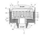
- FIG. 1 is a vertical cross-sectional view that illustrates a schematic internal configuration of a scroll compressor 100 according to a first embodiment.
- 2 is a cross-sectional view of the fixed scroll 1 and the orbiting scroll 2 of FIG. 1 taken along line AA, as viewed from below.
- 2 is a partial vertical cross-sectional view that illustrates the compression mechanism and its surroundings in the scroll compressor 100 according to the first embodiment.
- FIG. FIG. 2 is a vertical cross-sectional view showing a schematic configuration of the fixed scroll 1 of FIG.
- FIG. 2 is a schematic view of the fixed scroll 1 of FIG. 1 as viewed from below.
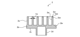
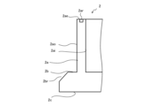
- FIG. 2 is a vertical cross-sectional view showing a schematic configuration of the orbiting scroll 2 of FIG. 1 .
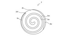
- FIG. 2 is a schematic view of the orbiting scroll 2 of FIG. 1 as viewed from above.
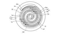
- 3 is a cross-sectional view showing suction paths 41, 42 of refrigerant into a compression chamber 30 in the fixed scroll 1 and the orbiting scroll 2 in FIG. 2 .
- 9 is a vertical cross-sectional view showing the BB section of the fixed scroll 1 and the orbiting scroll 2 in FIG. 8.
- 9 is a longitudinal sectional view showing the CC section of the fixed scroll 1 and the orbiting scroll 2 in FIG. 8.
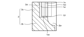
- FIG. 12 is a vertical cross-sectional view showing the DD section of the fixed scroll 1 and the orbiting scroll 2 in FIG. 11.
- 12 is a vertical cross-sectional view showing the EE section of the fixed scroll 1 and the orbiting scroll 2 in FIG. 11.
- FIG. 13 is a partial enlarged view of a portion Q1 in FIG. 12.
- FIG. 14 is a partially enlarged view of a portion Q2 in FIG. 13.
- FIG. 12 is an explanatory diagram illustrating a pressure difference between two compression chambers in FIG. 11.
- FIG. 7 is a vertical cross-sectional view showing a first modified example of the path expansion notch 2br in the orbiting scroll 2 of FIG. 6 .
- FIG. 7 is a vertical cross-sectional view showing a second modified example of the path expansion notch 2br in the orbiting scroll 2 of FIG. 6 .
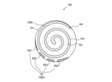
- 10 is a schematic diagram of an orbiting scroll 102 of a scroll compressor 100A according to a second embodiment, viewed from above.
- FIG. 10 is a schematic diagram of a fixed scroll 101 of a scroll compressor 100A according to a second embodiment, viewed from below.
- the present disclosure is not limited to the following embodiments, and various modifications can be made without departing from the spirit of the present disclosure.
- the present disclosure also includes all combinations of possible configurations among the configurations shown in the following embodiments.
- the combination of components is not limited to only the combinations in each embodiment, and components described in one embodiment can be applied to another embodiment.
- the scroll compressor shown in the drawings is an example of an apparatus to which the scroll compressor of the present disclosure is applied, and the scroll compressor shown in the drawings does not limit the applicable apparatus of the present disclosure.
- FIG. 1 is a vertical cross-sectional view showing a schematic internal configuration of a scroll compressor 100 according to the first embodiment.
- the flow of the refrigerant is indicated by an outline arrow.
- FIG. 2 is a cross-sectional view showing the A-A section of the fixed scroll 1 and the swing scroll 2 in FIG. 1 from below.
- FIG. 2 also shows the positions of two suction ports 26 formed in the frame 20.
- FIG. 2 shows the swing base plate 2b and its path expansion notch 2br, which are located below the A-A section in FIG. 1, by broken lines.
- FIG. 3 is a partial vertical cross-sectional view showing a schematic peripheral portion of the compression mechanism in the scroll compressor 100 according to the first embodiment. In FIG. 3, the thrust direction is indicated by an outline arrow.
- scroll compressor 100 is one of the components of a refrigeration cycle used in various industrial machines, such as refrigerators, freezers, vending machines, air conditioners, refrigeration systems, and water heaters.
- a scroll compressor 100 draws in a refrigerant circulating in a refrigeration cycle, compresses it, and discharges it in a high-temperature, high-pressure state.
- This scroll compressor 100 has a compression mechanism that combines a fixed scroll 1 and an orbiting scroll 2 that orbits relative to the fixed scroll 1, mounted in a sealed container 22 that is composed of a center shell 22a, an upper shell 22b, and a lower shell (not shown).
- the scroll compressor 100 also includes a rotary drive means made of an electric rotating machine or the like, mounted in the sealed container 22. In the sealed container 22, the compression mechanism is disposed on the upper side, and the rotary drive means is disposed on the lower side.
- the sealed container 22 is configured with an upper shell 22b above the center shell 22a, and a lower shell (not shown) below the center shell 22a.
- the lower shell (not shown) serves as an oil reservoir for storing lubricating oil.
- the center shell 22a is connected to a suction pipe 15 that is connected to the refrigerant circuit and takes in refrigerant gas from the refrigerant circuit.
- the upper shell 22b is connected to a discharge pipe 17 that is connected to the refrigerant circuit and discharges refrigerant gas to the refrigerant circuit.
- the inside of the center shell 22a forms a low-pressure chamber 18, and the inside of the upper shell 22b forms a high-pressure chamber 19.
- the fixed scroll 1 is composed of a fixed base plate 1b and a fixed spiral 1a, which is a spiral protrusion formed on one surface of the fixed base plate 1b.
- the swing scroll 2 is composed of a swing base plate 2b and a swing spiral 2a, which is a spiral protrusion formed on one surface of the swing base plate 2b, has substantially the same shape as the fixed spiral 1a, and is formed to mesh with the fixed spiral 1a.
- the swing scroll 2 and the fixed scroll 1 are stored in a frame 20 having two suction ports 26.
- the other surface of the swing base plate 2b acts as a thrust bearing surface 2c.
- An Oldham groove 2co is formed on the thrust bearing surface 2c of the swing scroll 2. Details of the structures of the fixed scroll 1 and the swing scroll 2 will be described later.
- the oscillating scroll 2 is designed so that the thrust bearing load generated during operation of the scroll compressor 100 is supported by the frame 20 via the thrust bearing surface 2c. If the frame 20 does not have sufficient hardness to withstand the thrust bearing load, a thrust plate (not shown) made of a material having sufficient hardness to withstand the thrust bearing load may be inserted between the thrust bearing surface 2c and the frame 20.
- the oscillating scroll 2 and the fixed scroll 1 are mounted in a sealed container 22 with the oscillating spiral 2a and the fixed spiral 1a combined with each other.
- the winding directions of the fixed spiral 1a and the oscillating spiral 2a are opposite to each other.
- a compression chamber 30 (the fixed scroll inward surface compression chamber 32 and the fixed scroll outward surface compression chamber 31) whose volume changes relatively with the oscillating motion of the oscillating scroll 2 described later is formed.
- the fixed scroll outward surface compression chamber 31 may be referred to as the first compression chamber
- the fixed scroll inward surface compression chamber 32 may be referred to as the second compression chamber.
- the compression mechanism is formed with the above-mentioned compression chamber 30, which is connected to the discharge port 16 at the end of the compression process, and a refrigerant suction chamber 40, which is provided upstream of the compression chamber 30 in the refrigerant flow direction and is connected to the suction port 26 of the frame 20.
- the compression chamber 30 is formed between the fixed base plate 1b and the oscillating base plate 2b, and between the oscillating spiral 2a and the fixed spiral 1a, and the refrigerant suction chamber 40 is provided between the fixed base plate 1b and the oscillating base plate 2b, inside the frame 20 and outside the compression chamber 30.
- the fixed scroll outward surface compression chamber 31 is formed between the fixed base plate 1b and the oscillating base plate 2b, between the outward surface 1ao of the fixed spiral 1a and the inward surface 2ai of the oscillating spiral 2a.
- the fixed scroll inward surface compression chamber 32 is formed between the fixed base plate 1b and the oscillating base plate 2b, between the outward surface 2ao of the oscillating spiral 2a and the inward surface 1ai of the fixed spiral 1a.
- one of the two suction ports 26 in the frame 20 is provided outside the outward surface 1ao of the fixed spiral 1a of the fixed scroll 1 and approximately near the end point 1af of the fixed spiral 1a in the circumferential direction, and the remaining one is provided outside the outward surface 2ao of the oscillating spiral 2a of the oscillating scroll 2 and approximately near the end point 2af of the oscillating spiral 2a in the circumferential direction.
- the end point 1af of the fixed spiral 1a means the end located at the outermost periphery of the fixed spiral 1a.
- the end point 2af of the oscillating spiral 2a means the end located at the outermost periphery of the oscillating spiral 2a.
- the two suction ports 26 are provided at positions 180° apart.
- the arrows indicate the flow of refrigerant drawn from the refrigerant suction chamber 40 into the fixed scroll outward surface compression chamber 31 and the fixed scroll inward surface compression chamber 32.
- the suction passage 41 which serves as the inlet for the refrigerant into the fixed scroll outward surface compression chamber 31, is provided near the end point 2af of the oscillating scroll 2a
- the suction passage 42 which serves as the inlet for the refrigerant into the fixed scroll inward surface compression chamber 32, is provided near the end point 1af of the fixed scroll 1a. Details of the suction passages 41 and 42 will be described later.
- tip seals 71, 72 are embedded in the tip surfaces 1ae, 2ae of the fixed spiral 1a and the oscillating spiral 2a. These tip seals 71, 72 prevent refrigerant leakage from the gaps G1, G2 (see FIG. 14 and FIG. 15 described later) between the tip surfaces 1ae, 2ae of each spiral and the base plate facing these tip surfaces 1ae, 2ae.
- multiple compression chambers are formed toward the center between the fixed spiral 1a and the oscillating spiral 2a, and the compression chambers closer to the discharge port 16 contain high-pressure refrigerant that has progressed through the compression process.
- the tip seals 71, 72 provided on the tip surfaces 1ae, 2ae of each spiral can prevent refrigerant leakage between radially adjacent compression chambers.
- the fixed scroll 1 is fixed to the frame 20 by bolts 7 or the like.
- a discharge port 16 is formed in the center of the fixed base plate 1b of the fixed scroll 1, which discharges the compressed, high-pressure refrigerant gas.
- the compressed, high-pressure refrigerant gas is then discharged into a high-pressure chamber 19 provided at the top of the fixed scroll 1.
- the refrigerant gas discharged into the high-pressure chamber 19 is then discharged into the refrigeration cycle via a discharge pipe 17.
- the discharge port 16 is provided with a discharge valve 33 that prevents the refrigerant from flowing back from the high-pressure chamber 19 to the discharge port 16 side.
- the oscillating scroll 2 is allowed to perform an orbital motion (oscillating motion) relative to the fixed scroll 1 without rotating on its axis, due to an Oldham ring 14 that prevents rotation.
- a hollow cylindrical boss portion 2d is formed in the approximate center of the surface (back surface) of the oscillating scroll 2 opposite the surface on which the oscillating spiral 2a is formed.
- An eccentric shaft portion 8a provided at the upper end of the main shaft 8 is inserted into this boss portion 2d.
- the Oldham ring 14 is interposed between the thrust bearing surface 2c, which is the surface opposite to the surface on which the orbiting scroll 2 is formed, and the frame 20.
- the Oldham ring 14 has protruding Oldham claws formed on the upper and lower surfaces.
- the Oldham claws formed on the upper surface of the Oldham ring 14 are housed so that they can slide in the Oldham grooves 2co formed on the thrust bearing surface 2c of the orbiting scroll 2, and the Oldham claws formed on the lower surface of the Oldham ring 14 are housed so that they can slide in the Oldham key grooves formed in the orbiting scroll insertion portion 20a of the frame 20.
- the Oldham ring 14 may also be installed on the surface on which the orbiting scroll 2a is formed on the orbiting base plate 2b.
- the frame 20 has a central opening in its center, and a cylindrical main bearing 21 extending downward is provided in the central opening.
- the main bearing 21 supports the rotation of the rotary drive means (particularly the main shaft 8).
- the outer periphery of the frame 20 serves as a housing section for housing the oscillating scroll 2.
- the housing section has a cylindrical peripheral wall section that surrounds the meshed fixed spiral 1a and oscillating spiral 2a, and a support wall section that supports the thrust bearing surface 2c of the oscillating base plate 2b.
- the outer periphery of the peripheral wall section of the frame 20 is fixed to the inside of the sealed container 22 (the inner surface of the upper part of the center shell 22a) by, for example, shrink fitting or welding.
- the support wall section of the frame 20 is provided with an oscillating scroll insertion section 20a that communicates with the central opening and in which the boss section 2d of the oscillating scroll is disposed.
- a suction port 26 is formed on the outer periphery of the support wall of the frame 20, which connects the low pressure chamber 18 below the support wall with the refrigerant suction chamber 40 above the support wall.
- An Oldham keyway is formed in the orbiting scroll insertion portion 20a.
- the rotary drive means is composed of a rotor 11 fixed to the main shaft 8, a stator 10, and the main shaft 8 which is a rotating shaft.
- the rotor 11 is fixed to the main shaft 8 by shrink fitting, and is rotated and rotates the main shaft 8 when electricity starts to flow to the stator 10.
- the stator 10 and the rotor 11 constitute an electric rotating machine.
- the rotor 11 is disposed below the first balance weight 12 which is fixed to the main shaft 8 together with the stator 10 which is fixed to the inner surface of the middle part of the center shell 22a by shrink fitting.
- the stator 10 is supplied with power via a power supply terminal 9 provided on the center shell 22a.
- the main shaft 8 rotates with the rotation of the rotor 11, causing the swing scroll 2 to orbit.
- the upper part of the main shaft 8 (near the eccentric shaft portion 8a) is rotatably supported by a main bearing 21 provided in the center of the frame 20.
- the lower part of the main shaft 8 is rotatably supported by a secondary bearing (not shown).
- a first balance weight 12 is provided on the upper part of the main shaft 8 to offset the imbalance with respect to the center of rotation of the main shaft 8 caused by the oscillating scroll 2 attached to the eccentric shaft portion 8a and oscillating.
- a second balance weight is provided on the lower part of the rotor 11 to offset the imbalance with respect to the center of rotation of the main shaft 8 caused by the oscillating scroll 2 attached to the eccentric shaft portion 8a and oscillating.
- the first balance weight 12 is fixed to the upper part of the main shaft 8 by shrink fitting, and the second balance weight (not shown) is fixed to the lower part of the rotor 11 integrally with the rotor 11.
- a first balance weight 12 fixed to the top of the main shaft 8 and a second balance weight (not shown) fixed to the bottom of the rotor 11 maintain static and dynamic balance against the eccentric revolution of the oscillating scroll 2.
- the oscillating scroll 2 which is eccentrically supported on the top of the main shaft 8 and whose rotation is suppressed by the Oldham ring 14, is oscillated and performs an orbital revolution.
- refrigerant gas flows from the external refrigeration cycle through the suction pipe 15 into the low pressure chamber 18 inside the center shell 22a.
- a portion of the refrigerant gas that flows into the low pressure chamber 18 flows into the refrigerant suction chamber 40 through two suction ports 26 provided in the frame 20.
- the remaining portion of the refrigerant gas passes through the notches (not shown) in the steel plate of the stator 10 to cool the electric rotating machine and the lubricating oil.
- the refrigerant that has flowed into the refrigerant suction chamber 40 is sucked into the compression chamber 30 through the suction paths 41, 42 in accordance with the relative swaying motion of the oscillating scroll 2a and the fixed scroll 1a of the compression mechanism, and the suction process (i.e., refrigerant intake into the compression chamber 30) begins.
- the suction process i.e., refrigerant intake into the compression chamber 30
- the volume of the compression chamber 30 expands as the oscillating scroll 2 revolves.
- the compression chamber 30 is in communication with the suction paths 41, 42.
- the compression chamber 30 closes, and the suction process of the refrigerant (i.e., refrigerant intake) is completed.
- the compression chamber 30 moves to the center of the oscillating scroll 2 due to the oscillating motion of the oscillating scroll 2, and the volume is reduced.
- the refrigerant gas sucked into the compression chamber 30 is compressed.
- the compressed refrigerant passes through the discharge port 16 of the fixed scroll 1, pushes open the discharge valve 33, and flows into the high-pressure chamber 19. It is then discharged from the sealed container 22 through the discharge pipe 17.
- the fixed volute 1a and the oscillating volute 2a are meshed at a 180-degree angle, and two suction paths (suction path 41 and suction path 42) are provided. Then, refrigerant is sucked into each of the two compression chambers (the fixed scroll outer surface side compression chamber 31 and the fixed scroll inner surface side compression chamber) that are formed at the same time, via the suction paths 41 and 42. Then, after the refrigerant is compressed in each compression chamber, the refrigerant compressed in the two compression chambers join together at the center of the oscillating scroll 2 and is discharged from the discharge port 16 to the high-pressure chamber 19.
- the thrust bearing load generated by the pressure of the refrigerant gas in the compression chamber 30 is supported by the frame 20 supporting the thrust bearing surface 2c.
- the centrifugal force and refrigerant gas load generated in the first balance weight 12 and second balance weight (not shown) as the main shaft 8 rotates are supported by the main bearing 21 and auxiliary bearing (not shown).
- the low-pressure refrigerant gas in the low-pressure chamber 18 and the high-pressure refrigerant gas in the high-pressure chamber 19 are separated by the fixed scroll 1 and frame 20, and are kept airtight.
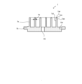
- Figure 4 is a vertical cross-sectional view showing the general configuration of the fixed scroll 1 of Figure 1.
- Figure 4 shows the fixed scroll 1 shown in Figure 1 upside down.
- Figure 5 is a schematic view of the fixed scroll 1 of Figure 1 viewed from below.
- Figure 6 is a vertical cross-sectional view showing the general configuration of the oscillating scroll 2 of Figure 1.
- Figure 7 is a schematic view of the oscillating scroll 2 of Figure 1 viewed from above.
- Figure 8 is a cross-sectional view showing the refrigerant suction paths 41, 42 to the compression chamber 30 in the fixed scroll 1 and oscillating scroll 2 of Figure 2.
- Figure 9 is a vertical cross-sectional view showing the B-B section of the fixed scroll 1 and oscillating scroll 2 of Figure 8.
- FIG. 10 is a vertical cross-sectional view showing the C-C section of the fixed scroll 1 and oscillating scroll 2 of Figure 8.
- FIG. 11 is a diagram showing the positional relationship between the path extension groove 1br and the end point 2af of the swinging scroll 2a in FIG. 8 when the rotation phase of the swinging scroll 2 is 0 [rad] (i.e., when the refrigerant intake is completed) and the positional relationship between the path extension notch 2br and the end point 1af of the fixed scroll 1a.
- the swinging base plate 2b and its path extension notch 2br which are located below the A-A cross section in FIG. 1, are shown by dashed lines.
- FIG. 12 is a vertical cross-sectional view showing the D-D cross section of the fixed scroll 1 and swinging scroll 2 in FIG. 11.
- FIG. 13 is a vertical cross-sectional view showing the E-E cross section of the fixed scroll 1 and swinging scroll 2 in FIG. 11. The structure of the fixed scroll 1 and swinging scroll 2 will be described in detail based on FIG. 4 to FIG. 13.
- seal grooves 1ar and 2ar with widths smaller than the tooth thicknesses T1 and T2 of the fixed and oscillating spirals 1a and 2a are formed on the tip surfaces 1ae and 2ae of the teeth of the fixed and oscillating spirals 1a and 2a, respectively.
- the above-mentioned tip seals 71 and 72 that suppress refrigerant leakage are attached to the seal grooves 1ar and 2ar.
- a path expansion groove 1br is formed on the lower surface (volute forming surface) of the fixed base plate 1b in a part of the area where the end point 2af (see FIG. 11) of the oscillating spiral 2a slides. More specifically, on the volute forming surface of the fixed base plate 1b, the path expansion groove 1br is formed outside the position of the outward surface 2ao of the oscillating spiral 2a when the intake of the refrigerant is completed (see FIG. 11 and FIG. 12).
- the path expansion groove 1br is formed so that at least a part of the path expansion groove 1br (the part of the path expansion groove 1br shown by the lattice pattern in FIG. 8) is positioned inside the position of the inward surface 2ai of the oscillating spiral 2a during the suction process of the refrigerant (see FIG. 8).
- the path expansion groove 1br may be referred to as the first lower surface portion.
- the path expansion groove 1br is formed on the spiral forming surface of the fixed base plate 1b, inward from the outer circumferential end, i.e., so that the edges remain.
- the cross-sectional shape of the path expansion groove 1br is rectangular.
- the fixed base plate 1b of the fixed scroll 1 serves to separate the low pressure of the refrigerant suction chamber 40 provided on the side of the spiral forming surface from the high pressure chamber 19 (see Figure 3) provided on the back side. Therefore, as described above, in the fixed base plate 1b, the recess for expanding the suction path 41 is made into a groove with edges remaining, and while expanding the suction path 41 more than before, it maintains its role of sealing high pressure and low pressure as before.
- the upper surface (volute forming surface) of the oscillating table 2b has a path expansion notch 2br formed in a part of the area where the end point 1af (see FIG. 11) of the fixed spiral 1a slides. More specifically, the path expansion notch 2br is formed on the volute forming surface of the oscillating table 2b outside the position of the outward surface 1ao of the fixed spiral 1a when the refrigerant intake is completed (see FIG. 11 and FIG. 13).
- the path expansion notch 2br is formed so that at least a part of the path expansion notch 2br (the part of the path expansion notch 2br shown in a lattice pattern in FIG. 8) is positioned inside the position of the inward surface 1ai of the fixed spiral 1a during the refrigerant intake process (see FIG. 8).
- the path expansion notch 2br may be referred to as the second lower surface portion.
- the path expansion notch 2br is formed on the spiral-forming surface of the oscillating plate 2b without leaving any edges on its outer peripheral end, i.e., the outer peripheral end of the oscillating plate 2b is also removed.
- the cross-sectional shape of the path expansion notch 2br is a curved surface such as an R-shape.
- the oscillating plate 2b of the oscillating scroll 2 has the role of receiving the gas load in the thrust direction (see Figure 3). Therefore, as described above, in the oscillating plate 2b, the recess for expanding the suction path 42 is cut out only on the spiral-forming surface side, and the area of the back surface of the oscillating plate 2b is secured as in the conventional case. As a result, the suction path 42 is expanded more than before, while the thrust load resistance is maintained as in the conventional case.
- the path expansion notch 2br is formed in the oscillating base plate 2b, so the weight of the oscillating scroll 2 is smaller than in the past. Therefore, the weight of the balancer (e.g., the first balance weight 12) can be lighter than in the past, and mechanical loss can be reduced.
- recesses such as the path expansion groove 1br and the path expansion notch 2br are provided on each of the spiral forming surfaces of the fixed base plate 1b and the oscillating base plate 2b. These recesses communicate with the compression chamber 30 (the fixed scroll outward surface side compression chamber 31 or the fixed scroll inward surface side compression chamber 32) during the refrigerant intake process shown in FIG. 8, and are separated from the compression chamber 30 when the refrigerant intake is completed as shown in FIG. 11.
- the suction paths 41, 42 of the present disclosure have a larger opening area to the compression chamber 30 than the conventional main suction paths 41m, 42m (see FIGS.
- the path expansion groove 1br has an arc shape extending in the circumferential direction, with one end located near the end point 2af of the oscillating spiral 2a in the circumferential direction, and is provided within a range of about 90° from this end along the oscillating spiral 2a.
- One end of the path expansion groove 1br is provided, for example, upstream of the refrigerant flow from the area where the end point 2af of the oscillating spiral 2a slides during the refrigerant intake process. This allows the refrigerant to flow into the expanded suction path 41e (see FIG. 9) from the circumferential direction during the refrigerant intake process.
- the path expansion notch 2br has an arc shape extending in the circumferential direction, and is provided in a range of about 120° in the circumferential direction, spanning before and after the end point 1af of the fixed spiral 1a.
- one end of the path expansion notch 2br is provided upstream of the refrigerant flow area where the end point 1af of the fixed spiral 1a slides during the refrigerant suction process. This allows the refrigerant to flow into the expanded suction path 42e (see FIG. 10) from the circumferential direction during the refrigerant suction process.
- FIG. 14 is a partial enlarged view of the Q1 portion of FIG. 12.
- FIG. 15 is a partial enlarged view of the Q2 portion of FIG. 13.
- the path expansion groove 1br and the path expansion notch 2br are formed on the respective spiral forming surfaces of the fixed base plate 1b or the oscillating base plate 2b outside the position of the inward surface 2ai, 1ai of the opposing spiral at the completion of the intake of the refrigerant, even if they are inside the position of the outward surface 2ao, 1ao, they are separated from the compression chamber 30 at the completion of the intake of the refrigerant.
- the position of the oscillating spiral 2a or the fixed spiral 1a in this case is shown by a dashed line.
- the path expansion groove 1br and the path expansion notch 2br are positioned outside or at the same position as the position of the outward surface 2ao, 1ao of the opposing spiral at the completion of the intake of the refrigerant, as shown in FIG. 11 to FIG. 15. The reasons for this are explained below.
- gaps G2 and G1 that serve as leakage paths for the refrigerant are formed between the volute forming surface of the fixed base plate 1b and the tip surface 2ae of the oscillating volute 2a, and between the volute forming surface of the oscillating base plate 2b and the tip surface 1ae of the fixed volute 1a, respectively.
- the fixed base plate 1b is formed with a path expansion groove 1br
- the oscillating base plate 2b is formed with a path expansion notch 2br and a path expansion notch 2br.
- FIG. 16 is an explanatory diagram that explains the pressure difference between the two compression chambers 30 in FIG. 11 (i.e., when intake is complete). Based on FIG. 16, the pressure difference between the fixed scroll outward surface side compression chamber 31 and the fixed scroll inward surface side compression chamber 32 will be explained.
- the path extension groove 1br of the fixed scroll 1 and the path extension notch 2br of the orbiting scroll 2 As shown in FIG. 16, in order to prevent a pressure difference from occurring between the two compression chambers (the fixed scroll inward surface compression chamber 32 and the fixed scroll outward surface compression chamber 31) formed at symmetrical positions, it is preferable to make the path extension groove 1br of the fixed scroll 1 and the path extension notch 2br of the orbiting scroll 2 as symmetrical as possible.
- a wasteful force i.e., a loss, occurs from one compression chamber (the one with the higher pressure) to the other compression chamber (the one with the lower pressure).
- the path extension groove 1br and the path extension notch 2br are made approximately symmetrical, the expansion areas of the refrigerant suction paths 41, 42 to the two compression chambers can be made approximately the same, and as a result, the pressure difference between the two compression chambers can be reduced and the loss can be reduced.
- the configuration of the path expansion groove 1br of the fixed scroll 1 and the path expansion notch 2br of the orbiting scroll 2 is not limited to the above configuration.
- the range and number of the path expansion grooves 1br and path expansion notches 2br in the circumferential direction do not have to be the range and number described above, and each of the path expansion grooves 1br and path expansion notches 2br may be divided into multiple parts. An embodiment in this case is shown in embodiment 2.
- the cross-sectional shapes of the path expansion groove 1br and the path expansion notch 2br are not limited to the above cross-sectional shapes.
- a modified example of the path expansion notch 2br shown in Figure 5 is described.
- FIG. 17 is a vertical cross-sectional view showing a first modified example of the path expansion notch 2br in the oscillating scroll 2 of FIG. 6.
- FIG. 18 is a vertical cross-sectional view showing a second modified example of the path expansion notch 2br in the oscillating scroll 2 of FIG. 6.
- the cross-sectional shape of the path expansion notch 2br shown in FIG. 17 is rectangular.
- the cross-sectional shape of the path expansion notch 2br shown in FIG. 18 is chamfered and has a triangular shape.
- the cross-sectional shape of the path expansion notch 2br is preferably one that ensures as much cross-sectional area as possible, but any cross-sectional shape is acceptable as long as the refrigerant can be drawn radially from the outward surface 1ao of the fixed scroll 1a, along the outward surface 1ao and the tip surface 1ae, into the space between the fixed scroll 1a and the oscillating scroll 2a (i.e., the compression chamber 30 during the suction process).
- the path expansion groove 1br of the fixed scroll 1 is preferably one that ensures as much cross-sectional area as possible, but any cross-sectional shape is acceptable as long as the refrigerant can be drawn radially from the outward surface 1ao of the fixed scroll 1a, along the outward surface 1ao and the tip surface 1ae, into the space between the fixed scroll 1a and the oscillating scroll 2a (i.e., the compression chamber 30 during the suction process).
- the path expansion groove 1br of the fixed scroll 1 is preferably
- the scroll compressor 100 of the first embodiment includes a sealed container 22, a compression mechanism in which a compression chamber 30 and a refrigerant suction chamber 40 are formed upstream of the compression chamber 30 in the refrigerant flow direction, and is provided within the sealed container 22.
- the compression mechanism includes a fixed scroll 1 having a fixed base plate 1b in which a discharge port 16 through which the refrigerant of the compression chamber 30 flows and a fixed spiral 1a provided on one surface of the fixed base plate 1b, a swinging base plate 2b facing the tooth tip (tip surface 1ae) of the fixed spiral 1a, and an oscillating scroll 2 having an oscillating spiral 2a provided on one surface of the oscillating base plate 2b so as to mesh with the fixed spiral 1a and form a first compression chamber and a second compression chamber between the fixed spiral 1a and the fixed spiral 1a.
- a first low surface portion (path expansion groove 1br) is formed on the surface of the fixed base plate 1b on the side where the fixed spiral 1a is provided, and a second low surface portion (path expansion notch 2br) is formed on the surface of the oscillating base plate 2b on the side where the oscillating spiral 2a is provided.
- the first low surface portion is arranged outside the outward surface 2ao of the oscillating spiral 2a when the refrigerant intake is completed, and is formed so as to be connected to the first compression chamber (fixed scroll outward surface side compression chamber 31) during the refrigerant intake process.
- the second low surface portion is arranged outside the outward surface 1ao of the fixed spiral 1a when the refrigerant intake is completed, and is formed so as to be connected to the second compression chamber (fixed scroll inward surface side compression chamber 32) during the refrigerant intake process.
- the first and second low surface portions can increase the cross-sectional area of the suction paths 41, 42 to each compression chamber. Furthermore, since the first and second low surface portions are positioned outside the outward faces 2ao, 1ao of the opposing spirals when the refrigerant intake is complete, even if the first and second low surface portions are provided, the leakage flow path between the tip faces 1ae, ae of the spirals and the opposing base plate does not widen, and refrigerant leakage from the first and second low surface portions after the intake is complete can be suppressed. Therefore, by increasing the cross-sectional area of the suction paths 41, 42 to the compression chambers more than before while keeping the refrigerant leakage flow path to a conventional size, the suction pressure loss can be reduced, and performance can be improved.
- the first lower surface is a groove formed on one surface (the surface on which the spiral is formed) of the fixed base plate 1b
- the second lower surface is a notch formed on the outer edge of the oscillating base plate 2b, cut out only on the side of one surface (the surface on which the spiral is formed) of the oscillating base plate 2b.
- the rear surface of the fixed base plate 1b and the rear surface of the oscillating base plate 2b each have the same area as before, so the function of separating high pressure and low pressure, and the function of receiving thrust loads can be maintained as before.
- FIG. 19 is a schematic diagram of the swing scroll 102 of the scroll compressor 100A according to the second embodiment as viewed from above.
- Fig. 20 is a schematic diagram of the fixed scroll 101 of the scroll compressor 100 according to the second embodiment as viewed from below.
- the scroll compressor 100 according to the second embodiment will be described with reference to Figs. 19 and 20. Note that in the second embodiment, differences from the first embodiment will be mainly described, and the same or corresponding parts as those in the first embodiment will be denoted by the same reference numerals and description thereof will be omitted.
- the scroll compressor according to the second embodiment will be referred to as scroll compressor 100A in order to distinguish it from the scroll compressor 100 according to the first embodiment.
- the path expansion groove 101br is provided intermittently in the circumferential direction on the fixed base plate 101b, and is composed of multiple groove portions (four groove portions R11, R12, R13, and R14 in Figure 20).
- the four groove portions R11, R12, R13, and R14 may not be distinguished from each other, and each may simply be referred to as groove portion R1.
- the path expansion notch 102br is provided intermittently in the circumferential direction on the oscillating base plate 102b, and is composed of multiple notch portions R2 (four notch portions R21, R22, R23, and R24 in Figure 19).
- the four cutouts R21, R22, R23, and R24 may not be distinguished from one another and may simply be referred to as cutout R2.
- the path expansion groove 101br may be referred to as the first bottom surface
- the path expansion cutout 102br may be referred to as the second bottom surface.
- each groove portion R1 in the second embodiment is shorter than the circumferential length of the path expansion groove 1br in the first embodiment, and the four groove portions R11, R12, R13, and R14 in the second embodiment are configured by dividing one path expansion groove 1br in the first embodiment into multiple portions in the circumferential direction.
- the tip surface 2ae of the teeth of the oscillating spiral 2a is supported by the portion between the groove portions R1 in the fixed base plate 101b, so that the oscillating spiral 2a can be prevented from overturning into the path expansion groove 101br.
- each cutout portion R2 in embodiment 2 is shorter than the circumferential length of the path expansion cutout 2br in embodiment 1, and the four R21, R22, R23, and R24 in embodiment 2 are configured by dividing one path expansion cutout 2br in embodiment 1 into multiple parts in the circumferential direction.
- the tip surface 1ae of the teeth of the fixed spiral 1a is supported by the portion between the cutout portions R2 in the oscillating base plate 102b, so that the fixed spiral 1a can be prevented from tipping over into the path expansion cutout 102br.
- the suction paths 41, 42 can be expanded more than in the conventional scroll compressor, resulting in improved performance.
- the first lower surface portion (path expansion groove 101br) and the second lower surface portion (path expansion notch 102br) are each provided intermittently in the circumferential direction.
- the tip surface 2ae of the teeth of the oscillating spiral 2a is supported by the portion between the groove portions R1 in the fixed base plate 101b, so that the oscillating spiral 2a can be prevented from overturning into the path expansion groove 101br.
- the fixed spiral 1a and the oscillating spiral 2a are described as being configured to have a roughly symmetrical shape, but as long as the above-mentioned effect is obtained, they may be configured to have an asymmetrical shape.
- the first lower surface portion formed on the fixed base plate 1b is a groove (path expansion groove 1br) formed on the spiral-forming surface of the fixed base plate 1b
- the second lower surface portion formed on the oscillating base plate 2b is a notch (path expansion notch 2br) formed by cutting out only the spiral-forming surface of the oscillating base plate 2b, but the first lower surface portion may be a notch and the second lower surface portion may be a groove.
Landscapes
- Engineering & Computer Science (AREA)
- Mechanical Engineering (AREA)
- General Engineering & Computer Science (AREA)
- Rotary Pumps (AREA)
Priority Applications (2)
| Application Number | Priority Date | Filing Date | Title |
|---|---|---|---|
| PCT/JP2023/012148 WO2024201644A1 (ja) | 2023-03-27 | 2023-03-27 | スクロール圧縮機 |
| JP2025509275A JPWO2024201644A1 (https=) | 2023-03-27 | 2023-03-27 |
Applications Claiming Priority (1)
| Application Number | Priority Date | Filing Date | Title |
|---|---|---|---|
| PCT/JP2023/012148 WO2024201644A1 (ja) | 2023-03-27 | 2023-03-27 | スクロール圧縮機 |
Publications (1)
| Publication Number | Publication Date |
|---|---|
| WO2024201644A1 true WO2024201644A1 (ja) | 2024-10-03 |
Family
ID=92903991
Family Applications (1)
| Application Number | Title | Priority Date | Filing Date |
|---|---|---|---|
| PCT/JP2023/012148 Ceased WO2024201644A1 (ja) | 2023-03-27 | 2023-03-27 | スクロール圧縮機 |
Country Status (2)
| Country | Link |
|---|---|
| JP (1) | JPWO2024201644A1 (https=) |
| WO (1) | WO2024201644A1 (https=) |
Citations (2)
| Publication number | Priority date | Publication date | Assignee | Title |
|---|---|---|---|---|
| JPH05231356A (ja) * | 1992-02-21 | 1993-09-07 | Toyota Autom Loom Works Ltd | スクロール型圧縮機 |
| JPH11336678A (ja) * | 1998-05-27 | 1999-12-07 | Hitachi Ltd | スクロール流体機械 |
-
2023
- 2023-03-27 WO PCT/JP2023/012148 patent/WO2024201644A1/ja not_active Ceased
- 2023-03-27 JP JP2025509275A patent/JPWO2024201644A1/ja active Pending
Patent Citations (2)
| Publication number | Priority date | Publication date | Assignee | Title |
|---|---|---|---|---|
| JPH05231356A (ja) * | 1992-02-21 | 1993-09-07 | Toyota Autom Loom Works Ltd | スクロール型圧縮機 |
| JPH11336678A (ja) * | 1998-05-27 | 1999-12-07 | Hitachi Ltd | スクロール流体機械 |
Also Published As
| Publication number | Publication date |
|---|---|
| JPWO2024201644A1 (https=) | 2024-10-03 |
Similar Documents
| Publication | Publication Date | Title |
|---|---|---|
| US20120148434A1 (en) | Scroll Fluid Machine | |
| CN111971477B (zh) | 涡旋压缩机 | |
| JP2000320475A (ja) | 容積形流体機械 | |
| JP5506839B2 (ja) | スクロール圧縮機及び空気調和装置 | |
| EP3567212B1 (en) | Compressor having oldham's ring | |
| JP6366833B2 (ja) | スクロール圧縮機 | |
| US11976653B2 (en) | Scroll compressor with suppressed reduction of rotational moment | |
| JP6607970B2 (ja) | スクロール圧縮機 | |
| JP2012184709A (ja) | スクロール圧縮機 | |
| WO2024201644A1 (ja) | スクロール圧縮機 | |
| JP7764806B2 (ja) | スクロール型電動圧縮機 | |
| JPH10259701A (ja) | 容積型流体機械 | |
| JP2020112143A (ja) | スクロール型流体機械 | |
| JP7689309B2 (ja) | スクロール圧縮機 | |
| JP3132328B2 (ja) | スクロール形流体機械 | |
| JP6195466B2 (ja) | スクロール圧縮機 | |
| KR102548470B1 (ko) | 올담링을 구비한 압축기 | |
| JP7701663B1 (ja) | スクロール圧縮機、及び冷凍装置 | |
| JP7701664B1 (ja) | スクロール圧縮機、及び冷凍装置 | |
| CN113454341B (zh) | 涡旋式压缩机 | |
| JP7702647B2 (ja) | スクロール圧縮機 | |
| JP4301122B2 (ja) | スクロール圧縮機 | |
| JP6116333B2 (ja) | スクロール圧縮機 | |
| WO2023162058A1 (ja) | スクロール圧縮機 | |
| JP2026054672A (ja) | スクロール圧縮機及び冷凍サイクル装置 |
Legal Events
| Date | Code | Title | Description |
|---|---|---|---|
| 121 | Ep: the epo has been informed by wipo that ep was designated in this application |
Ref document number: 23930284 Country of ref document: EP Kind code of ref document: A1 |
|
| WWE | Wipo information: entry into national phase |
Ref document number: 2025509275 Country of ref document: JP |
|
| NENP | Non-entry into the national phase |
Ref country code: DE |
|
| 122 | Ep: pct application non-entry in european phase |
Ref document number: 23930284 Country of ref document: EP Kind code of ref document: A1 |