WO2024201612A1 - 通信装置、トラヒック制御方法、及びプログラム - Google Patents
通信装置、トラヒック制御方法、及びプログラム Download PDFInfo
- Publication number
- WO2024201612A1 WO2024201612A1 PCT/JP2023/012007 JP2023012007W WO2024201612A1 WO 2024201612 A1 WO2024201612 A1 WO 2024201612A1 JP 2023012007 W JP2023012007 W JP 2023012007W WO 2024201612 A1 WO2024201612 A1 WO 2024201612A1
- Authority
- WO
- WIPO (PCT)
- Prior art keywords
- transmission
- communication device
- traffic
- message
- root
- Prior art date
- Legal status (The legal status is an assumption and is not a legal conclusion. Google has not performed a legal analysis and makes no representation as to the accuracy of the status listed.)
- Ceased
Links
Images










Classifications
-
- H—ELECTRICITY
- H04—ELECTRIC COMMUNICATION TECHNIQUE
- H04L—TRANSMISSION OF DIGITAL INFORMATION, e.g. TELEGRAPHIC COMMUNICATION
- H04L47/00—Traffic control in data switching networks
- H04L47/10—Flow control; Congestion control
Definitions
- the present invention relates to the technical field of traffic control in packet communications.
- micro data centers In recent years, data centers have been moving towards micro data centers, where small data centers are distributed over short distances, from the perspective of efficient use of power, accommodating low-latency applications, and flexible floor design. In such an environment, it is expected that communication between micro data centers will increase and be mixed with communication within the data center. It will also be important to reduce communication latency between data centers.
- ExpEther registered trademark
- ultra-low latency packet transmission as a method for PCIe (registered trademark) communication between distant servers.
- multiple switches connect each server, and certain switches are connected to transmission devices such as WDM (Wavelength Division Multiplexing) systems, with the network between data centers being configured with WDM systems.
- WDM Widelength Division Multiplexing
- the internal bus signals inside the server are directly converted to optical signals and transmitted between data centers.
- the present invention has been made in consideration of the above points, and aims to provide a technology that makes it possible to reduce packet discards in communication devices that connect to other bases at a base equipped with multiple communication devices.
- a communication device used as a first communication device at a base including a first communication device that connects to another base and a plurality of second communication devices that connect devices, an estimation unit that estimates a future transmission amount at a transmission port of a second communication device based on a message received from the second communication device; and a control unit that executes traffic control for a second communication device or the communication device based on the transmission amount estimated by the estimation unit.
- the disclosed technology provides a technology that enables a base station equipped with multiple communication devices to reduce packet discards in communication devices that connect to other base stations.
- FIG. 1 is a diagram showing a basic NW configuration for connecting two DCs.
- FIG. 1 is a diagram illustrating an example of a network configuration within a DC.
- FIG. 1 is a diagram for explaining an assumed communication method.
- FIG. 1 is a diagram for explaining an assumed communication method.
- FIG. 1 is a diagram illustrating an example of a system configuration according to an embodiment of the present invention. 1 is a flowchart for explaining an overview of the operation of the system.
- FIG. 13 is a diagram showing a pattern of traffic control.
- FIG. 11 is a diagram for explaining a specific example of a counting method. 13 is a flowchart showing a transmission permission determination process.
- FIG. 2 is a configuration diagram of a route SW 10 according to the first embodiment.
- FIG. 1 is a diagram illustrating an example of a network configuration within a DC.
- FIG. 1 is a diagram for explaining an assumed communication method.
- FIG. 1 is a diagram for explaining an assumed communication method.
- FIG. 1
- FIG. 2 is a configuration diagram of a SW20 in the first embodiment.
- 4 is a flowchart showing the overall flow of processing by a route SW 10 in the first embodiment.
- 1 is a flowchart showing a processing procedure of a traffic estimation process 1.
- 11 is a flowchart showing a procedure of a transfer process in each SW 20.
- FIG. 11 is a diagram illustrating an example of a sequence according to the first embodiment.
- FIG. 11 is a diagram illustrating an example of a sequence according to the first embodiment.
- FIG. 11 is a configuration diagram of a route SW 10 according to a second embodiment.
- 10 is a flowchart showing the overall flow of processing by a route SW 10 in a second embodiment.
- 13 is a flowchart showing a processing procedure of a traffic estimation process 2.
- FIG. 1 is a flowchart showing a processing procedure of a traffic estimation process 1.
- 11 is a flowchart showing a procedure of a transfer process in each SW 20.
- FIG. 11 is a diagram illustrating an example of a sequence according to a second embodiment.
- FIG. 11 is a diagram illustrating an example of a sequence according to a second embodiment.
- FIG. 1 is a diagram illustrating a configuration of a communication device 100.
- FIG. 2 illustrates an example of a hardware configuration of a communication device 100.
- DC data center
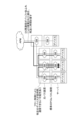
- FIG. 1 shows a basic NW (network) configuration connecting two DCs.
- FIG. 1 shows (1) the NW configuration between DCs, which is labeled “global,” and (2) the NW configuration within a DC, which is labeled “local.” Both (1) between DCs and (2) within a DC have a hierarchical structure. If it is only between DCs, ultra-low latency packet transmission technology can be applied as is. However, for a NW that includes the inside of a DC, there are issues such as packet discard (packet loss) as mentioned above.
- PCIe registered trademark
- PCIe registered trademark
- Figure 2 shows an example of a network configuration based on the above assumption.
- Figure 2 shows an example of a network configuration within one of multiple DCs that perform inter-DC communication.
- Examples 1 and 2 will be described as specific examples, but first, matters common to Examples 1 and 2 will be described. After explaining matters common to Examples 1 and 2, Examples 1 and 2 will be described separately.
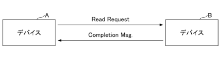
- device A sends a Read Request to device B.
- the Read Request includes the amount of data to be read from device B (request size, requested data amount) as a Length value.
- the Read Request may also be called a Read Request Message.
- Device A that sends the Read Request may also be called the Requester.
- Completion Msg. a Completion Message
- the Completion Msg. for a Read Request contains the size of data requested in the Read Request.
- the Completion Msg. may also be called a response message or a completion notification.
- device A sends a Write Request to device B.
- the Write Request includes the data that device A wants to write to device B.
- the Write Request also includes the amount of data (requested size) as a Length value.
- the Write Request may also be called a write request message.
- Device A, which sends the Write Request may also be called the Requester.
- PCIe registered trademark
- the technology according to the present invention is not limited to PCIe (registered trademark).
- the technology can be applied to any communication method that uses messages such as read requests/write requests similar to Read Request/Write Request.
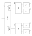
- Fig. 5 shows an example of a system configuration (example of a network configuration) in this embodiment.
- Fig. 5 shows an example of a configuration within a DC.
- the configuration shown in Fig. 5 is a common configuration to Examples 1 and 2 described later.
- the numbers that make up the device name may be written in parentheses to make it easier to distinguish between them and the numbers in the drawings. Also, in explanations of operation, etc., the numbers may not be written in parentheses to avoid complicating the notation.
- SWs other than the root SW collectively when there is no distinction between SW1, 2, etc., they will be written as SW20.
- Dev will be written as Dev30.
- SW1 (20-1) and SW2 (20-2) are connected under the root SW10.
- Dev1 (30-1) and Dev2 (30-2) are connected to SW1 (20-1)
- Dev3 (30-3) and Dev4 (30-4) are connected to SW2 (20-2).
- the root SW 10 is a SW that connects between DCs.
- Each Dev 30 is, for example, a device equipped with a PCIe (registered trademark) function.
- Each switch, including the root switch 10, may be called a bus switch.
- the root switch 10 may be called a root bus switch.
- Each SW may be, for example, a PCIe (registered trademark) switch, a CXL switch, ExpEther (registered trademark), or an optical bus device.
- an optical bus device is a device that directly converts and switches frames (e.g., PCIe (registered trademark) frames) for ultra-low latency packet transmission into optical signals.
- SW and devices other than SW may be collectively referred to as communication devices.
- “Devices other than SW” include devices that operate in the same way as SW, but are not called SW.
- the root SW 10 and each SW 20 each have a port for connecting to other SWs or devices. Packets can be sent and received to and from other SWs or devices via the port.
- port 11 and port 12 of the root SW 10 are shown as an example.
- a port may be called an input/output IF unit.
- the functional unit that transmits data at a port may be called a transmitting port
- the functional unit that receives data at a port may be called a receiving port.
- the transmitting port has a buffer that stores the data (packets) to be transmitted.
- This buffer may be called a transmit buffer or a transmit queue.
- the transmit buffer may be external to the port. In other words, the transmit buffer may be connected to the port.
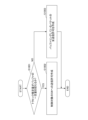
- the root SW 10 estimates the amount of traffic that will occur from the received message (Read Request, etc.) and controls the SW 20 under control so that the transmission buffer of the root SW 10 for the destination SW 20 does not overflow with transmission data. Alternatively, the root SW 10 controls the transmission (transfer) of the received packet. An overview of the processing procedure will be described with reference to the flowchart of FIG. 6.
- the route SW 10 estimates the traffic volume for each transmission buffer of the port for each destination SW 20 of the route SW 10 from the received message.
- the route SW 10 performs a transmission permission determination process according to the calculated traffic estimation volume and the transmission permission policy.
- the root SW 10 If transmission is permitted, in S3, the root SW 10 notifies the controlled SW (e.g., subordinate SW) of transmission permission. In S4, each SW 20 transmits according to the transmission permission conditions. Note that if the controlled SW is the root SW 10 itself, the root SW 10 may transmit in S4 after determining in S2 that transmission is permitted.
- the controlled SW e.g., subordinate SW
- the traffic volume can be estimated using (1) a method for estimating the traffic volume from read/write requests, and (2) a method for estimating the traffic volume from only read requests.
- the Length value in the packet header is used to estimate the traffic volume.
- the headers of each Read Request and Write Request contain a Length field, and it is possible to estimate the amount of traffic being sent and received between devices from the value of this field.
- packet loss is suppressed by notifying the buffer amount between endpoints, but in the technology related to this embodiment, packet transmission at each SW10/20 is controlled so that the traffic amount estimated by the root SW10 does not exceed the buffer of the port addressed to SW20, thereby reducing packet discards and the resulting delays due to retransmission.
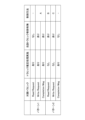
- Traffic control patterns 7 there are two traffic control patterns in this embodiment: pattern 1 and pattern 2. Details will be described in Example 1 (corresponding to pattern 1) and Example 2 (corresponding to pattern 2), but an overview will be given here.
- Pattern 1 corresponds to the case where "(1) traffic volume is estimated from read/write requests”
- pattern 2 corresponds to the case where "traffic volume is estimated only from read requests.”
- Pattern 1 shown in "A", as a method of controlling the traffic of Write Requests and Completion Messages, when each SW 20 receives a packet from Dev 30, it temporarily buffers the packet. If the traffic volume estimated from the headers of the Read Request and Write Request, etc., is not enough to overflow the root SW 10's transmission buffer for the destination SW, the root SW 10 notifies each SW 20 of permission to transmit. If the volume would overflow, it instructs the SW 20 requesting transmission to the relevant SW 20 to perform time-division transmission.
- the root SW 10 temporarily holds (buffers) the received read request, and if the Completion Msg size estimated from the read request does not cause the buffer to overflow, it sends the read request to the destination SW 20.
- the control method for the Write Request traffic shown in "C” is as follows: The Write Request is immediately sent to SW20 and root SW10, and if the amount of free buffer space in the sending port (sending queue) from root SW10 to destination SW20 is sufficiently small compared with the estimated amount of traffic due to the Read Request (i.e. the estimated amount of traffic for Completion Msg.), SW20 and root SW10 immediately discard the Write Request and return a NAK to the requesting Dev30.
- Counting method 1 Count traffic for each pair of sending and receiving Dev30.
- Counting method 2 Count traffic for each downstream transmission buffer to SW20 to which the requester is connected.
- the total counters for each send/receive pair included in the port for destination SW 20 of root SW 10 are compared with the buffer capacity of the sending port to evaluate whether or not to allow transmission.
- the condition may be that the traffic of each send/receive pair is sent equally, or each send/receive pair may be weighted for transmission.
- the transmission permission information is created in the order counted by the counter (first come, first served).
- Figure 8 is a diagram illustrating the flow of sending and receiving packets in comparison with Figure 5.
- Dev3 and Dev4 each send a Read Request packet to Dev1.
- B1 and B2 respectively show images of the sending buffers.
- Counting method 1 The route SW 10 performs counting with separate counters for each transmitting/receiving pair (Dev1 and Dev3, Dev1 and Dev4). That is, the route SW 10 counts the traffic generated by the Completion Msg from Dev1 to Dev3 and the traffic generated by the Completion Msg from Dev1 to Dev4 with separate counters.
- Counting method 2 The route SW 10 counts the traffic associated with the downstream transmission buffer B2 destined for the SW2 to which the requesters Dev3 and Dev4 are connected, in one counter. In other words, the route SW 10 counts the traffic generated by the Completion Msg destined for Dev3 and Dev4, in the same counter.
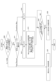
- the route SW 10 judges whether the estimated traffic volume for the destination SW exceeds a certain amount of the destination transmission buffer of the route SW 20.
- “Exceeding a certain amount of the transmission buffer” means, for example, that "if the total storage capacity of the transmission buffer is taken as 100%, when the estimated traffic volume is added to the current storage capacity of the transmission buffer, the storage capacity of the transmission buffer exceeds X%.”
- X is a number that is determined in advance.
- the root SW 10 calculates the conditions under which traffic can be transmitted without overflowing the buffer (e.g., time sharing between SWs) and creates a transmission permission for the controlled SW.
- the root SW 10 creates a transmission permission for all packets buffered by the controlled SW.
- the adjustment is performed only once, but a notification may be sent each time the transmission permission amount or time changes based on a predetermined scheduling algorithm. For example, if packets remain in the buffer of each SW after the first transmission permission, the transmission permission decision may be made again after a certain period of time has passed.
- Example 1 is an example that uses traffic control pattern 1
- Example 2 is an example that uses traffic control pattern 2.
- Example 1 First, a first embodiment using pattern 1 will be described.
- a method for estimating traffic volume and a method for controlling traffic in the first embodiment are as follows.
- Example 1 Traffic volume estimation method Write Request: Each SW 20 counts the amount of write requests for each destination from memory information of a TLP (Transaction Layer Packet) and information on the entire PCIe (registered trademark) memory address, and notifies the root SW 10 at regular intervals or sequentially. Alternatively, only the header information of the write request received by each SW may be transmitted to the root SW 10, and the root SW 10 may estimate the traffic amount from the header information.
- TLP Transaction Layer Packet
- PCIe registered trademark
- Completion Msg The route SW 10 utilizes the Length field of the Read Request to estimate the traffic volume of the Completion Msg that is sent as a reply to the Requester.
- Example 1 Traffic Control Method> Control over Read Requests: There will be no new traffic control, and each device will transmit in a non-blocking manner.
- SW20 can send only if it has been notified of permission to send by root SW10. If permission to send is not given from root SW10, the data is buffered in a sending queue (sending buffer) within SW20. Root SW10 sends permission to send according to the following policy.
- transmission permission is given in a time-division manner between the SW20s requesting transmission to the relevant SW20.
- transmission permission may be given to the SW20 to be controlled for each certain amount of transmission data.
- Root SW10 sends permission to send according to the following policy.
- transmission is permitted if the estimated traffic volume is small and buffer overflow will not occur (estimated traffic volume does not exceed a certain value for the transmission buffer). In other words, transmission is permitted as long as the size of the Completion Msg to the Requester does not cause buffer overflow.
- transmission permission is given in a time-division manner between the SW20s requesting transmission to the relevant SW20.
- transmission permission may be given to the SW20 to be controlled for each certain amount of transmission data.
- Fig. 10 shows an example of the functional configuration of the root SW 10.
- Fig. 10 mainly shows the configuration related to the processing in the first embodiment, and does not show other functions provided in a general SW.
- the route SW 10 includes an input/output IF unit 11, a traffic volume estimation unit 12, a transmission permission determination unit 13, a transmission permission transmission unit 14, and a forwarding processing unit 15.
- the input/output IF unit 11 inputs and outputs information from and to the outside.
- the traffic volume estimation unit 12 estimates the traffic volume generated for each destination SW 20 from received messages (e.g., header information of a Read Request, Completion Msg., or Write Request, or information for traffic estimation).
- the traffic volume estimation unit 12 has a counter for estimating traffic volume.
- the transmission feasibility determination unit 13 compares the buffer volume of the transmission port for each destination SW 20 with the traffic volume estimated by the traffic volume estimation unit 12, and determines whether or not the "Completion Msg. and/or Write Request" buffered by the subordinate SW 20 can be transmitted.
- the transmission permission transmitter 14 If it is determined that transmission is permitted, the transmission permission transmitter 14 notifies the SW 20 in question of information indicating that transmission is permitted and the amount of data that can be transmitted.
- the forwarding processor 15 performs packet forwarding and other processes.
- Fig. 11 shows an example of the functional configuration of the SW 20.
- Fig. 11 shows a configuration mainly related to the processing in the first embodiment, and does not show other functions of a general SW.
- the SW 20 includes an input/output IF unit 21, a traffic estimation information notification unit 22, a transmission permission receiving unit 23, a packet buffer unit 24, and a forwarding processing unit 25.
- the input/output IF unit 21 inputs and outputs information from the outside.
- the traffic estimation information notification unit 22 generates traffic estimation information including header information extracted from a received packet (e.g., Write Request) or traffic estimation information including length information stored in the header information, and notifies the route SW 10.
- the transmission permission receiving unit 23 receives the transmission permission notified from the root SW 10, and according to the transmission permission conditions, retrieves the packet stored in the packet buffer unit 24 and transmits it to the root SW 10 or Dev 30 via the forwarding processing unit 25.
- the packet buffer unit 24 buffers packets (e.g. Completion Msg., Write Request) received from Dev 30 until permission to send is given from the route SW 10.
- the forwarding processing unit 25 performs packet forwarding processing, etc.
- the input/output IF unit 11 receives the message.
- the message is passed to the traffic volume estimation unit 12.
- the traffic volume estimation unit 12 performs traffic estimation process 1.
- the traffic estimation process 1 will be described later.
- S12 if the type of the received message is a "Read Request, Write Request header, or traffic estimation volume", the process proceeds to S13, and if the type of the received message is a "Write Request or Completion Msg.”, the process proceeds to S15.
- the transmission permission determination unit 13 performs a transmission permission determination process.
- the transmission permission transmission unit 14 notifies each SW 20 that is permitted to transmit of the transmission permission.
- the forwarding processing unit 15 forwards the packet to the destination.
- ⁇ Traffic Estimation Process 1 in Route SW 10> 13 is a flowchart showing the procedure of the traffic estimation process 1 in the route SW 10. The procedure of the traffic estimation process 1 in the route SW 10 will be described with reference to FIG.
- the traffic volume estimation unit 12 judges the type of the received message. If the type is "Read Request”, the process proceeds to S11-2, where the type is "Completion Msg. If the type is "Write Request header or traffic estimated amount”, the process proceeds to S11-3, and if the type is "Write Request header or traffic estimated amount", the process proceeds to S11-4.
- the traffic volume estimation unit 12 adds the size of the Completion Msg obtained from the Length in the header of the received Read Request to the traffic estimation counter.
- the traffic volume estimation unit 12 subtracts the size of the received Completion Msg. or Write Request from the traffic estimation counter.
- the traffic volume estimation unit 12 adds the size of the Length in the received Write Request header or the size of the received traffic estimation volume to the traffic estimation counter.
- Each SW 20> 14 is a flowchart showing the procedure of the transfer process in each SW 20 under the root SW 10. The transfer process in each SW 20 will be described with reference to FIG.
- the forwarding processing unit 25 determines whether the received packet was forwarded from the root SW 10 or sent from Dev 30. If the packet was forwarded from the root SW 10, the process proceeds to S27. If the packet was sent from Dev 30, the process proceeds to S21.
- the transfer processing unit 25 determines the type of message received from Dev30. If the type is "Read Request”, the process proceeds to S25; if the type is "Write Request”, the process proceeds to S22; if the type is "Completion Msg.”, the process proceeds to S26.
- the packet buffer unit 24 temporarily buffers the packet.
- the traffic estimation information notification unit 22 notifies the route SW 10 of the transmission volume in the Write Request.
- the traffic estimation information notification unit 22 may transfer only the header of the received Write Request to the route SW 10. Then, proceed to S24.
- the packet buffer unit 24 temporarily buffers the packet and the process proceeds to S24.
- the transmission permission receiving unit 23 determines whether transmission permission has been received from the route SW 10, and if so, proceeds to S25.
- the forwarding processing unit 25 forwards the packet to the destination.
- the forwarding processing unit 25 forwards the packet to the destination Dev 30.
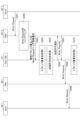
- Dev1 sends a Read Request to SW1.
- SW1 forwards the Read Request to root SW10.
- root SW10 executes traffic volume estimation process 1, and in S104 forwards the Read Request to SW2.
- SW2 forwards the Read Request to Dev3.
- Dev3 sends a Completion Msg. to SW2, and in S108, SW2 buffers the Completion Msg.
- the root SW10 performs a transmission permission determination process. If it is determined that SW2 is permitted to transmit, in S109 the root SW10 transmits a transmission permission notification to SW2. In S110, SW2 transmits a Completion Msg. to the root SW10. In S111, the root SW10 performs a traffic volume estimation process 1, and in S112, transfers the Completion Msg. to SW1. In S113, SW1 transfers the Completion Msg. to Dev1.
- Example of sequence in the first embodiment (Example of Write Request control)> An example of a sequence when a Write Request is transmitted from Dev3 to Dev1 will be described with reference to FIG.
- Dev3 sends a Write Request to SW2.
- SW2 buffers the Write Request.
- SW2 notifies root SW10 of the estimated traffic volume or the Write Request header information.
- the route SW10 performs traffic volume estimation process 1 in S204, and performs transmission permission determination process in S205.
- root SW10 transmits a transmission permission notification to SW2.
- SW2 transmits a Write Request to root SW10.
- root SW10 transfers the Write Request to SW1, and in S209, SW1 transfers the Write Request to Dev1.
- root SW10 performs traffic volume estimation process 1.
- the default is to stop transmission, and when transmission is permitted, the root SW 10 notifies permission/stop (or transmission amount), but this is just one example.
- the default may be to permit transmission, and when transmission is not permitted, the root SW 10 notifies stop/resume.
- the amount of data that can be transmitted in units of bytes or DW (4 bytes)
- PCIe registered trademark
- Example 2 Next, a second embodiment will be described using traffic control pattern 2.
- a traffic volume estimation method and a traffic control method in the second embodiment are as follows.
- Example 2 Traffic volume estimation method Write Request: In the second embodiment, traffic volume estimation for write requests is not performed.
- Completion Msg The root SW 10 utilizes the Length field of the Read Request to estimate the amount of data in the Completion Msg that will be sent to the Requester as a reply.
- Example 2 Traffic Control Method> Control over Read Requests: The route SW 10 temporarily buffers the data, and then controls the transmission of the read request according to the following scheduling policy based on the estimated traffic volume calculated above and the free space in the downstream transmission buffer destined for the SW 20 to which the requester is connected.
- a Write Request can be immediately sent to SW20 and root SW10, but if the amount of free buffer space in the transmission queue (transmission buffer) from the root SW10 to the destination SW20 is sufficiently small compared with the estimated traffic volume of the Completion Msg. estimated from the Read Request, the Write Request is immediately discarded on the SW20 and root SW10 side and a NAK is returned to the requesting Dev30 (prompting retransmission).
- FIG. 17 shows an example of the functional configuration of the root SW 10 in Example 2.
- FIG. 17 mainly shows the configuration related to the processing in Example 2, and does not show other functions that are provided in a general SW.
- the route SW 10 includes an input/output IF unit 11, a forwarding processing unit 15, a Write Request transmission permission determination unit 16, a traffic volume estimation unit 17, a transmission permission determination unit 18, and a packet buffer unit 19.
- the input/output IF unit 11 inputs and outputs information from and to the outside.
- the forwarding processing unit 15 performs packet forwarding processing, etc.
- the Write Req. transmission feasibility determination unit 16 determines whether a received Write Request message can be sent.
- the traffic volume estimation unit 17 estimates the traffic volume generated for each destination SW 20 from the received messages (e.g. Read Request, Completion Msg.).
- the transmission permission determination unit 18 compares the buffer volume of the transmission port for each destination SW 20 with the traffic volume estimated by the traffic volume estimation unit 17 to determine whether or not the Read Request that it is buffering can be transmitted.
- the packet buffer unit 19 buffers the received packet (Read Request) until permission to transmit is given by the transmission permission determination unit 18.
- the transfer processing unit 15 receives a message in S31, and determines the type of the received message in S32. If the type of the received message is a "Read Request or Completion Msg.”, the process proceeds to S33, and if the type of the received message is a "Write Request", the process proceeds to S38.
- the traffic estimation unit 17 performs traffic estimation process 2.
- the process proceeds to S35, and if the type of the received message is a "Completion Msg.”, the process proceeds to S37.
- the transmission permission determination unit 18 proceeds to S40 if the free space in the transmission buffer of the transmission queue toward the destination SW 20 is sufficiently small compared to the traffic estimate of the Completion Msg. estimated from the Read Request (Yes in S38), and proceeds to S39 if it is not sufficiently small (No in S38).
- the forwarding processing unit 15 forwards the received Write Request packet to the destination SW 20.
- the forwarding processing unit 15 discards the received Write Request packet and sends a NAK to the source Dev 30.
- ⁇ Traffic Estimation Process 2 in Route SW 10> 19 is a flowchart showing the procedure of the traffic estimation process 2 in the route SW 10. The procedure of the traffic estimation process 2 in the route SW 10 will be described with reference to FIG.
- the traffic volume estimation unit 17 determines the type of the received message. If the type is "Read Request”, the process proceeds to S33-3, and if the type is "Completion Msg.”, the process proceeds to S33-2.
- the traffic volume estimation unit 17 adds the size of the Completion Msg obtained from the Length in the header of the received Read Request to the traffic estimation counter.
- the traffic volume estimation unit 17 subtracts the size of the received Completion Msg. from the traffic estimation counter.
- Dev1 sends a Read Request to SW1.
- SW1 forwards the Read Request to root SW10.
- root SW10 buffers the Read Request, in S304 performs traffic volume estimation process 2, and in S305 performs transmission permission determination process.
- root SW10 forwards the Read Request to SW2.
- SW2 forwards the Read Request to Dev3.
- Dev3 sends a Completion Msg. to SW2, and in S309, SW2 forwards the Completion Msg. to root SW10.
- the root SW10 transfers the Completion Msg. to SW1, and in S311, SW1 transfers the Completion Msg. to Dev1.
- the traffic estimation unit 17 executes the traffic estimation process 2.
- Dev3 sends a Write Request to SW2.
- SW2 transfers the Write Request to the root SW10.
- the transmission permission determination unit 18 of the root SW10 performs the transmission permission determination process, determines that transmission is not possible as described above, discards the Write Request, and returns a NAK to SW2 in S404.
- SW2 returns a NAK to Dev3.
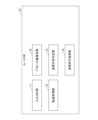
- (Other configuration examples) 22 shows a configuration example of a communication device 100 including a function of estimating traffic volume and performing traffic control in the route SW 10.
- the communication device 100 shown in FIG. 22 may be the route SW 10 itself, or may be an external device in the case where the function of estimating traffic volume and performing traffic control in the route SW 10 is provided outside the switching function.
- the communication device 100 includes an estimation unit 110 and a control unit 120.
- the communication device 100 corresponds to a communication device used as a first communication device in a base that includes a first communication device that connects to other bases and a plurality of second communication devices that connect devices.
- the estimation unit 110 estimates the future transmission volume (traffic volume) at the transmission port of the communication device 100 based on a message received from a second communication device.
- the control unit 120 executes traffic control for the second communication device or the communication device 100 based on the transmission volume estimated by the estimation unit 110.
- the communication device 100 can be realized, for example, by causing a computer to execute a program.
- This computer may be a physical computer or a virtual machine on the cloud.
- communication device 100 can be realized by using hardware resources such as a CPU and memory built into a computer to execute a program corresponding to the processing performed by the device.
- the program can be recorded on a computer-readable recording medium (such as a portable memory) and then stored or distributed.
- the program can also be provided via a network such as the Internet or email.
- FIG. 23 is a diagram showing an example of the hardware configuration of the computer.
- the computer in FIG. 23 has a drive device 1000, an auxiliary storage device 1002, a memory device 1003, a CPU 1004, an interface device 1005, a display device 1006, an input device 1007, an output device 1008, etc., all of which are interconnected by a bus BS.
- the computer may further include a GPU.
- the program that realizes the processing on the computer is provided by a recording medium 1001, such as a CD-ROM or a memory card.
- a recording medium 1001 storing the program is set in the drive device 1000, the program is installed from the recording medium 1001 via the drive device 1000 into the auxiliary storage device 1002.
- the program does not necessarily have to be installed from the recording medium 1001, but may be downloaded from another computer via a network.
- the auxiliary storage device 1002 stores the installed program as well as necessary files, data, etc.
- the memory device 1003 When an instruction to start a program is received, the memory device 1003 reads out and stores the program from the auxiliary storage device 1002.
- the CPU 1004 realizes functions related to the communication device 100 in accordance with the program stored in the memory device 1003.
- the interface device 1005 is used as an interface for connecting to a network, etc.
- the display device 1006 displays a GUI (Graphical User Interface) based on a program, etc.
- the input device 1007 is composed of a keyboard and mouse, buttons, a touch panel, etc., and is used to input various operational instructions.
- the output device 1008 outputs the results of calculations.
- a communication device used as a first communication device in a base including a first communication device that connects to another base and a plurality of second communication devices that connect devices, an estimation unit that estimates a future transmission amount at a transmission port of a second communication device based on a message received from the second communication device; and a control unit that executes traffic control for a second communication device or the communication device based on the transmission amount estimated by the estimation unit.
- the message is a read request message
- the estimation unit estimates a transmission volume of traffic toward a transmission source of the read request message based on a requested data volume of the read request message.
- the communication device wherein the control unit executes transmission control of a write request message received by the communication device based on an available buffer amount of a transmission port.
- a non-transitory storage medium storing a program for causing a computer to function as each unit in the communication device according to any one of claims 1 to 6.
Landscapes
- Engineering & Computer Science (AREA)
- Computer Networks & Wireless Communication (AREA)
- Signal Processing (AREA)
- Data Exchanges In Wide-Area Networks (AREA)
Abstract
Description
ある第2通信装置から受信したメッセージに基づいて、前記通信装置の送信ポートにおける今後の送信量を推定する推定部と、
前記推定部により推定された送信量に基づいて、第2通信装置又は前記通信装置に対するトラヒック制御を実行する制御部と
を備える通信装置が提供される。
図1に、2つのDCを接続する基本的なNW(ネットワーク)構成を示す。図1は、「グローバル」と記載されている(1)DC間のNW構成と、「ローカル」と記載されている(2)DC内のNW構成を示す。(1)DC間、(2)DC内の何れも階層構造を有する。DC間のみであれば超低遅延パケット伝送技術をそのまま適用可能である。しかし、DC内までを含めたNWに関しては、前述したようなパケット廃棄(パケットロス)などの課題がある。
まず、本実施の形態において想定する通信方法を説明する。本実施の形態では、PCIe(登録商標)機能を備えるデバイス間で、図3、図4に示す通信方法で通信が行われることを想定する。なお、これらの通信方法は、PCIe(登録商標)の代表的な通信方法である。図3、図4において、デバイスAとデバイスBとの間には1以上のSWが存在するが、図3、図4にはSWを図示していない。
図5に、本実施の形態におけるシステム構成例(NW構成例)を示す。図5は、DC内の構成の例を示すものである。図5に示す構成は、後述する実施例1、2に共通の構成である。
次に、システムの動作の概要を説明する。本実施の形態では、ルートSW10が、受信したメッセージ(Read Request等)から、この後に発生するであろうトラヒック量を推定し、ルートSW10の宛先SW20向けの送信バッファが送信データで溢れないよう、配下のSW20を制御する。もしくは、ルートSW10において、受信したパケットの送信(転送)を制御する。図6のフローチャートを参照して処理手順の概要を説明する。
次に、トラヒック量の推定方法を説明する。本実施の形態では、トラヒック量の推定方法として、(1)Read/Write Requestから推定する方法、及び(2)Read Requestのみから推定する方法がある。
本実施の形態では、図7に示すように、トラヒック制御のパターンとして、パターン1とパターン2がある。詳細については実施例1(パターン1に対応)、及び実施例2(パターン2に対応)で説明するが、ここでは概要を説明する。
次に、トラヒックのカウント方法と送信許可判定について説明する。本実施の形態におけるカウント方法として、下記のカウント方法1とカウント方法2がある。カウント方法1とカウント方法2のいずれの方法を用いてもよい。
ルートSW10は、送受信ペア毎(Dev1とDev3、Dev1とDev4)に別々のカウンタでカウントを行う。つまり、ルートSW10は、Dev1からDev3へのCompletion Msgにより発生するトラヒックと、Dev1からDev4へのCompletion Msgにより発生するトラヒックとを別々のカウンタでカウントする。
ルートSW10は、RequesterであるDev3、 Dev4が接続されたSW2宛ての下り送信バッファB2に紐付けられるトラヒックを1つのカウンタでカウントする。つまり、ルートSW10は、Dev3、Dev4宛てのCompletion Msgにより発生するトラヒックを同一のカウンタでカウントする。
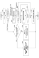
次に、ルートSW10における送信許可判定処理を図9のフローチャートを参照して説明する。前述したとおり、本実施の形態には、トラヒック制御のパターンとしてパターン1とパターン2があるが、図9に示すフローは、パターン1とパターン2で共通である。なお、パターン1のケースでは、制御対象SWはルートSW10配下のSW20となり、パターン2のケースでは、ルートSW10自身が制御対象SWとなる。
まず、パターン1を用いる実施例1を説明する。実施例1におけるトラヒック量推定方法、及び、トラヒック制御方法は下記のとおりである。
Write Request:
各SW20でTLP(Transaction Layer Packet)のメモリ情報とPCIe(登録商標)メモリアドレス全体の情報から、送信先ごとにWrite Request量をカウントし、一定周期毎または逐次、ルートSW10に通知する。もしくは、各SWで受信したWrite Requestのヘッダ情報のみルートSW10に送信してルートSW10が、ヘッダ情報からトラヒック量を推定してもよい。
ルートSW10は、Read RequestのLengthフィールドを活用し、返信としてRequester側に送られるCompletion Msgのトラヒック量を推定する。
Read Requestに対する制御:
新規のトラヒック制御はなく、各デバイスからノンブロッキングでの送信とする。
Dev30からSW20への送信に関しては新規のトラヒック制御はなし。
Dev30からSW20への送信に関しては新規のトラヒック制御はなし。
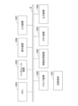
図10に、ルートSW10の機能構成例を示す。図10は、主に実施例1での処理に関わる構成を示しており、その他の一般的なSWが備える機能は図示していない。
図11に、SW20の機能構成例を示す。図11は、主に実施例1での処理に関わる構成を示しており、その他の一般的なSWが備える機能は図示していない。図11に示すように、 SW20は、入出力IF部21、トラヒック推定用情報通知部22、送信許可受信部23、パケットバッファ部24、転送処理部25を備える。
図12のフローチャートを参照して、実施例1のルートSW10における処理全体のフローを説明する。
図13は、ルートSW10におけるトラヒック推定処理1の処理手順を示すフローチャートである。図13を参照して、ルートSW10におけるトラヒック推定処理1の処理手順を説明する。
もしくはWrite Request」であればS11-3に進み、種別が「Write Requestヘッダ、もしくはトラヒック推定量」であればS11-4に進む。
図14は、ルートSW10配下の各SW20における転送処理の手順を示すフローチャートである。図14を参照して、各SW20における転送処理を説明する。
図15を参照して、Dev1からDev3へRead Requestを送信した時のシーケンス例を説明する。
図16を参照して、Dev3からDev1へWrite Requestを送信した時のシーケンス例を説明する。
本実施例1において、以上説明したトラヒック制御の例では、送信停止をデフォルトとし、送信許可の場合にルートSW10から許可・停止(or送信量)を通知することとしているが、これは一例である。トラヒック制御において、送信許可をデフォルトとし、送信不可の場合にルートSW10から停止・再開を通知してもよい。また、PCIe(登録商標)のフロー制御のように送信可能なデータ量(バイトor DW(4byte)単位)を管理し、ルートSW10がデータ量を更新してもよい。
次に、トラヒック制御のパターン2を用いる実施例2を説明する。実施例2におけるトラヒック量推定方法、トラヒック制御方法は下記のとおりである。
Write Request:
実施例2ではWrite Requestについてのトラヒック量推定を行わない。
ルートSW10は、Read RequestのLengthフィールドを活用し、返信としてRequester側に送られるCompletion Msgのデータ量を推定する。
Read Requestに対する制御:
ルートSW10で一旦バッファし、Requesterが接続されたSW20宛の、上記で算出した推定トラヒック量と下り送信バッファ空き容量に基づき、下記のスケジューリングポリシーに従ってRead Requestの送信制御を行う。
Write RequestはSW20、ルートSW10まですぐに送信可能とするが、ルートSW10から宛先SW20に向けた送信キュー(送信バッファ)の空バッファ量が、Read Requestから推定したCompletion Msg.のトラヒック推定量と比較して十分小さい場合、SW20、ルートSW10側で即座にWrite Requestを破棄し、要求元Dev30へのNAKを返す(再送を促す)。
新規のトラヒック制御は行わない。
<実施例2:ルートSW10の構成>
実施例2において、ルートSW10配下のSW20としては通常の機能を持つものを使用することができる。
図18のフローチャートを参照して、ルートSW10における処理全体のフローを説明する。
図19は、ルートSW10におけるトラヒック推定処理2の処理手順を示すフローチャートである。図19を参照して、ルートSW10におけるトラヒック推定処理2の処理手順を説明する。
図20を参照して、Dev1からDev3へRead Requestを送信した時のシーケンス例を説明する。
図21を参照して、Dev3からDev1へWrite Requestを送信した時のシーケンス例を説明する。本シーケンス例では、Write Requestを受信し、トラヒック推定量と空きバッファの比較を実施した結果、送信不可と判定した場合の流れを示す。なお、送信可と判定された場合、ルートSW10は受信したパケットを宛先に転送する。
ルートSW10においてトラヒック量推定、及びトラヒック制御を行う機能を含む通信装置100の構成例を図22に示す。図22に示す通信装置100は、ルートSW10そのものであってもよいし、ルートSW10におけるトラヒック量推定、及びトラヒック制御を行う機能を、スイッチング機能の外部に備えることとした場合のその外部の装置であってもよい。
通信装置100は、例えば、コンピュータにプログラムを実行させることにより実現できる。このコンピュータは、物理的なコンピュータであってもよいし、クラウド上の仮想マシンであってもよい。
以上説明したとおり、本実施の形態で説明した技術により、ルートSW10の送信バッファが溢れないよう、ルートSW10や配下のSW20を制御することで、DC内通信のようにトラヒック量が多い場合でも、パケット廃棄を少なくすることが可能となる。
(付記項1)
他の拠点との接続を行う第1通信装置と、デバイスを接続する複数の第2通信装置とを備える拠点において、前記第1通信装置として使用される通信装置であって、
ある第2通信装置から受信したメッセージに基づいて、前記通信装置の送信ポートにおける今後の送信量を推定する推定部と、
前記推定部により推定された送信量に基づいて、第2通信装置又は前記通信装置に対するトラヒック制御を実行する制御部と
を備える通信装置。
(付記項2)
前記メッセージは読込要求メッセージであり、前記推定部は、前記読込要求メッセージの要求データ量に基づいて、前記読込要求メッセージの送信元に向けたトラヒックの送信量を推定する
付記項1に記載の通信装置。
(付記項3)
前記メッセージは、書込要求メッセージから取得された要求データ量を含むメッセージであり、前記推定部は、前記要求データ量に基づいて、前記書込要求メッセージの送信先に向けたトラヒックの送信量を推定する
付記項1に記載の通信装置。
(付記項4)
前記制御部は、読込要求メッセージに対する応答メッセージの送信制御、又は、書込要求メッセージに対する送信制御を、第2通信装置に対して実行する
付記項1に記載の通信装置。
(付記項5)
前記メッセージは読込要求メッセージであり、前記制御部は、前記推定部により推定された、前記読込要求メッセージに対する応答メッセージの送信量に基づいて、前記読込要求メッセージの送信制御を実行する
付記項1に記載の通信装置。
(付記項6)
前記制御部は、送信ポートの空きバッファ量に基づいて、前記通信装置が受信した書込要求メッセージの送信制御を実行する
付記項1に記載の通信装置。
(付記項7)
他の拠点との接続を行う第1通信装置と、デバイスを接続する複数の第2通信装置とを備える拠点において、前記第1通信装置として使用される通信装置が実行するトラヒック制御方法であって、
ある第2通信装置から受信したメッセージに基づいて、前記通信装置の送信ポートにおける今後の送信量を推定する推定ステップと、
前記推定ステップにより推定された送信量に基づいて、第2通信装置又は前記通信装置に対するトラヒック制御を実行する制御ステップと
を備えるトラヒック制御方法。
(付記項8)
コンピュータを、付記項1ないし6のうちいずれか1項に記載の通信装置における各部として機能させるためのプログラムを記憶した非一時的記憶媒体。
11 入出力IF部
12 トラヒック量推定部
13 送信可否判定部
14 送信許可送信部
15 転送処理部1
16 Write Req.送信可否判定部
17 トラヒック量推定部
18 送信可否判定部
19 パケットバッファ部
20 SW
21 入出力IF部
22 トラヒック推定用情報通知部
23 送信許可受信部
24 パケットバッファ部
25 転送処理部
30 Dev
1000 ドライブ装置
1001 記録媒体
1002 補助記憶装置
1003 メモリ装置
1004 CPU
1005 インタフェース装置
1006 表示装置
1007 入力装置
1008 出力装置
Claims (8)
- 他の拠点との接続を行う第1通信装置と、デバイスを接続する複数の第2通信装置とを備える拠点において、前記第1通信装置として使用される通信装置であって、
ある第2通信装置から受信したメッセージに基づいて、前記通信装置の送信ポートにおける今後の送信量を推定する推定部と、
前記推定部により推定された送信量に基づいて、第2通信装置又は前記通信装置に対するトラヒック制御を実行する制御部と
を備える通信装置。 - 前記メッセージは読込要求メッセージであり、前記推定部は、前記読込要求メッセージの要求データ量に基づいて、前記読込要求メッセージの送信元に向けたトラヒックの送信量を推定する
請求項1に記載の通信装置。 - 前記メッセージは、書込要求メッセージから取得された要求データ量を含むメッセージであり、前記推定部は、前記要求データ量に基づいて、前記書込要求メッセージの送信先に向けたトラヒックの送信量を推定する
請求項1に記載の通信装置。 - 前記制御部は、読込要求メッセージに対する応答メッセージの送信制御、又は、書込要求メッセージに対する送信制御を、第2通信装置に対して実行する
請求項1に記載の通信装置。 - 前記メッセージは読込要求メッセージであり、前記制御部は、前記推定部により推定された、前記読込要求メッセージに対する応答メッセージの送信量に基づいて、前記読込要求メッセージの送信制御を実行する
請求項1に記載の通信装置。 - 前記制御部は、送信ポートの空きバッファ量に基づいて、前記通信装置が受信した書込要求メッセージの送信制御を実行する
請求項1に記載の通信装置。 - 他の拠点との接続を行う第1通信装置と、デバイスを接続する複数の第2通信装置とを備える拠点において、前記第1通信装置として使用される通信装置が実行するトラヒック制御方法であって、
ある第2通信装置から受信したメッセージに基づいて、前記通信装置の送信ポートにおける今後の送信量を推定する推定ステップと、
前記推定ステップにより推定された送信量に基づいて、第2通信装置又は前記通信装置に対するトラヒック制御を実行する制御ステップと
を備えるトラヒック制御方法。 - コンピュータを、請求項1ないし6のうちいずれか1項に記載の通信装置における各部として機能させるためのプログラム。
Priority Applications (2)
| Application Number | Priority Date | Filing Date | Title |
|---|---|---|---|
| PCT/JP2023/012007 WO2024201612A1 (ja) | 2023-03-24 | 2023-03-24 | 通信装置、トラヒック制御方法、及びプログラム |
| JP2025509248A JPWO2024201612A1 (ja) | 2023-03-24 | 2023-03-24 |
Applications Claiming Priority (1)
| Application Number | Priority Date | Filing Date | Title |
|---|---|---|---|
| PCT/JP2023/012007 WO2024201612A1 (ja) | 2023-03-24 | 2023-03-24 | 通信装置、トラヒック制御方法、及びプログラム |
Publications (1)
| Publication Number | Publication Date |
|---|---|
| WO2024201612A1 true WO2024201612A1 (ja) | 2024-10-03 |
Family
ID=92904069
Family Applications (1)
| Application Number | Title | Priority Date | Filing Date |
|---|---|---|---|
| PCT/JP2023/012007 Ceased WO2024201612A1 (ja) | 2023-03-24 | 2023-03-24 | 通信装置、トラヒック制御方法、及びプログラム |
Country Status (2)
| Country | Link |
|---|---|
| JP (1) | JPWO2024201612A1 (ja) |
| WO (1) | WO2024201612A1 (ja) |
Citations (3)
| Publication number | Priority date | Publication date | Assignee | Title |
|---|---|---|---|---|
| JP2006323729A (ja) * | 2005-05-20 | 2006-11-30 | Hitachi Ltd | マルチパス制御をする装置及びシステム |
| JP2007280236A (ja) * | 2006-04-11 | 2007-10-25 | Hitachi Ltd | バックアップ方法およびバックアッププログラム |
| JP2010198187A (ja) * | 2009-02-24 | 2010-09-09 | Nippon Telegr & Teleph Corp <Ntt> | iSCSIセッションのTCPコネクション数制御方法、iSCSIホスト装置、およびiSCSIイニシエータの構成プログラム。 |
-
2023
- 2023-03-24 WO PCT/JP2023/012007 patent/WO2024201612A1/ja not_active Ceased
- 2023-03-24 JP JP2025509248A patent/JPWO2024201612A1/ja active Pending
Patent Citations (3)
| Publication number | Priority date | Publication date | Assignee | Title |
|---|---|---|---|---|
| JP2006323729A (ja) * | 2005-05-20 | 2006-11-30 | Hitachi Ltd | マルチパス制御をする装置及びシステム |
| JP2007280236A (ja) * | 2006-04-11 | 2007-10-25 | Hitachi Ltd | バックアップ方法およびバックアッププログラム |
| JP2010198187A (ja) * | 2009-02-24 | 2010-09-09 | Nippon Telegr & Teleph Corp <Ntt> | iSCSIセッションのTCPコネクション数制御方法、iSCSIホスト装置、およびiSCSIイニシエータの構成プログラム。 |
Also Published As
| Publication number | Publication date |
|---|---|
| JPWO2024201612A1 (ja) | 2024-10-03 |
Similar Documents
| Publication | Publication Date | Title |
|---|---|---|
| RU2584449C2 (ru) | Система управления связью, коммутационный узел и способ управления связью | |
| EP3720069B1 (en) | Packet sending method and device | |
| US20200252337A1 (en) | Data transmission method, device, and computer storage medium | |
| US20030169688A1 (en) | System and method for dynamic rate flow control | |
| US20060203730A1 (en) | Method and system for reducing end station latency in response to network congestion | |
| CN104954253A (zh) | 用于数据中心覆盖网络的基于PCIe的主机网络加速器(HNA) | |
| WO2018233425A1 (zh) | 网络拥塞的处理方法、装置及系统 | |
| US12040995B2 (en) | Control apparatus, resource allocation method and program | |
| WO2009107089A2 (en) | Apparatus and method for shared buffering between switch ports | |
| CN104954252A (zh) | 在高性能、可扩展和无掉话的数据中心交换结构内的流控制 | |
| JP2014127790A (ja) | 情報処理装置および方法、並びにプログラム | |
| US20090274049A1 (en) | Non-blocked network system and packet arbitration method thereof | |
| JP5082145B2 (ja) | ノード装置およびその帯域制御方法 | |
| US10063481B1 (en) | Network endpoint congestion management | |
| CN112714081A (zh) | 一种数据处理方法及其装置 | |
| CA3119033C (en) | Method and apparatus for dynamic track allocation in a network | |
| US10237170B2 (en) | Flow switch, controller and relay apparatus | |
| WO2012131806A1 (en) | Retransmission control system and retransmission control method | |
| WO2024201612A1 (ja) | 通信装置、トラヒック制御方法、及びプログラム | |
| JP7456603B2 (ja) | スイッチ装置 | |
| JP5492709B2 (ja) | 帯域制御方法及び帯域制御装置 | |
| CN117615273A (zh) | 一种数据调度方法及装置 | |
| US20130039172A1 (en) | Communication apparatus, communication method, and computer product | |
| JP2015106865A (ja) | 通信装置、通信システム、通信方法、及び通信プログラム | |
| JP4630231B2 (ja) | パケット処理システム、パケット処理方法、およびプログラム |
Legal Events
| Date | Code | Title | Description |
|---|---|---|---|
| 121 | Ep: the epo has been informed by wipo that ep was designated in this application |
Ref document number: 23930253 Country of ref document: EP Kind code of ref document: A1 |
|
| ENP | Entry into the national phase |
Ref document number: 2025509248 Country of ref document: JP Kind code of ref document: A |
|
| WWE | Wipo information: entry into national phase |
Ref document number: 2025509248 Country of ref document: JP |
|
| NENP | Non-entry into the national phase |
Ref country code: DE |
|
| 122 | Ep: pct application non-entry in european phase |
Ref document number: 23930253 Country of ref document: EP Kind code of ref document: A1 |