WO2024201550A1 - 車載用制御装置 - Google Patents
車載用制御装置 Download PDFInfo
- Publication number
- WO2024201550A1 WO2024201550A1 PCT/JP2023/011700 JP2023011700W WO2024201550A1 WO 2024201550 A1 WO2024201550 A1 WO 2024201550A1 JP 2023011700 W JP2023011700 W JP 2023011700W WO 2024201550 A1 WO2024201550 A1 WO 2024201550A1
- Authority
- WO
- WIPO (PCT)
- Prior art keywords
- voltage
- conversion unit
- relay
- low
- battery
- Prior art date
- Legal status (The legal status is an assumption and is not a legal conclusion. Google has not performed a legal analysis and makes no representation as to the accuracy of the status listed.)
- Ceased
Links
Images


Classifications
-
- B—PERFORMING OPERATIONS; TRANSPORTING
- B60—VEHICLES IN GENERAL
- B60L—PROPULSION OF ELECTRICALLY-PROPELLED VEHICLES; SUPPLYING ELECTRIC POWER FOR AUXILIARY EQUIPMENT OF ELECTRICALLY-PROPELLED VEHICLES; ELECTRODYNAMIC BRAKE SYSTEMS FOR VEHICLES IN GENERAL; MAGNETIC SUSPENSION OR LEVITATION FOR VEHICLES; MONITORING OPERATING VARIABLES OF ELECTRICALLY-PROPELLED VEHICLES; ELECTRIC SAFETY DEVICES FOR ELECTRICALLY-PROPELLED VEHICLES
- B60L3/00—Electric devices on electrically-propelled vehicles for safety purposes; Monitoring operating variables, e.g. speed, deceleration or energy consumption
-
- B—PERFORMING OPERATIONS; TRANSPORTING
- B60—VEHICLES IN GENERAL
- B60L—PROPULSION OF ELECTRICALLY-PROPELLED VEHICLES; SUPPLYING ELECTRIC POWER FOR AUXILIARY EQUIPMENT OF ELECTRICALLY-PROPELLED VEHICLES; ELECTRODYNAMIC BRAKE SYSTEMS FOR VEHICLES IN GENERAL; MAGNETIC SUSPENSION OR LEVITATION FOR VEHICLES; MONITORING OPERATING VARIABLES OF ELECTRICALLY-PROPELLED VEHICLES; ELECTRIC SAFETY DEVICES FOR ELECTRICALLY-PROPELLED VEHICLES
- B60L53/00—Methods of charging batteries, specially adapted for electric vehicles; Charging stations or on-board charging equipment therefor; Exchange of energy storage elements in electric vehicles
- B60L53/20—Methods of charging batteries, specially adapted for electric vehicles; Charging stations or on-board charging equipment therefor; Exchange of energy storage elements in electric vehicles characterised by converters located in the vehicle
-
- B—PERFORMING OPERATIONS; TRANSPORTING
- B60—VEHICLES IN GENERAL
- B60L—PROPULSION OF ELECTRICALLY-PROPELLED VEHICLES; SUPPLYING ELECTRIC POWER FOR AUXILIARY EQUIPMENT OF ELECTRICALLY-PROPELLED VEHICLES; ELECTRODYNAMIC BRAKE SYSTEMS FOR VEHICLES IN GENERAL; MAGNETIC SUSPENSION OR LEVITATION FOR VEHICLES; MONITORING OPERATING VARIABLES OF ELECTRICALLY-PROPELLED VEHICLES; ELECTRIC SAFETY DEVICES FOR ELECTRICALLY-PROPELLED VEHICLES
- B60L58/00—Methods or circuit arrangements for monitoring or controlling batteries or fuel cells, specially adapted for electric vehicles
- B60L58/10—Methods or circuit arrangements for monitoring or controlling batteries or fuel cells, specially adapted for electric vehicles for monitoring or controlling batteries
- B60L58/18—Methods or circuit arrangements for monitoring or controlling batteries or fuel cells, specially adapted for electric vehicles for monitoring or controlling batteries of two or more battery modules
- B60L58/20—Methods or circuit arrangements for monitoring or controlling batteries or fuel cells, specially adapted for electric vehicles for monitoring or controlling batteries of two or more battery modules having different nominal voltages
-
- H—ELECTRICITY
- H02—GENERATION; CONVERSION OR DISTRIBUTION OF ELECTRIC POWER
- H02J—ELECTRIC POWER NETWORKS; CIRCUIT ARRANGEMENTS OR SYSTEMS FOR SUPPLYING OR DISTRIBUTING ELECTRIC POWER; SYSTEMS FOR STORING ELECTRIC ENERGY
- H02J7/00—Circuit arrangements for charging or discharging batteries or for supplying loads from batteries
Definitions
- This disclosure relates to an in-vehicle control device.
- Patent Document 1 discloses a configuration in which power is supplied from a lithium-ion battery to a lead battery and a group of electrical loads via a step-up/step-down converter (voltage conversion unit).
- Patent Document 1 The group of electrical loads in Patent Document 1 includes electrical loads that operate in the parked state.
- Patent Document 1 is configured to supply power from a lithium-ion battery to a lead battery, and from the lead battery to the electrical loads that operate in the parked state.
- the lead battery is repeatedly charged and discharged even when the vehicle is parked, which raises concerns that the lead battery may deteriorate more easily.
- a system main relay relay
- the system main relay may also deteriorate more easily than the lead battery.
- This disclosure was made based on the above-mentioned circumstances, and aims to provide an in-vehicle control device that can at least prevent excessive deterioration of the relay.
- the in-vehicle control device includes: An in-vehicle control device for use in an in-vehicle system including a high-voltage battery, a high-voltage load, and a low-voltage load, a relay provided between the high voltage battery and the high voltage load; A first voltage conversion unit provided between the relay and the low-voltage load; a second voltage conversion unit provided in parallel with the relay and the first voltage conversion unit; a control unit that controls the relay, the first voltage conversion unit, and the second voltage conversion unit, the first voltage conversion unit performs a first conversion operation of converting a voltage input from the high-voltage battery side through the relay into a low voltage lower than an output voltage from the high-voltage battery and outputting the low-voltage load side; the second voltage conversion unit performs a second conversion operation of converting a voltage input from the high-voltage battery side into the low-voltage and outputting the low-voltage load side;
- the control unit controls the relay to an on state while the vehicle is traveling, while
- This configuration helps prevent excessive deterioration of the relay.
- FIG. 1 is a block diagram illustrating an example of an in-vehicle system including an in-vehicle control device according to a first embodiment.
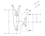
- FIG. 2 is a circuit diagram illustrating an example of the configuration of the first voltage conversion unit and the second voltage conversion unit according to the first embodiment.
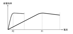
- FIG. 3 is a graph showing an example of power supply efficiency versus output current of each of the first voltage conversion unit and the second voltage conversion unit.
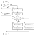
- FIG. 4 is a flowchart illustrating an example of control by the control unit in the first embodiment.
- FIG. 5 is a block diagram illustrating an in-vehicle system including the in-vehicle control device according to the second embodiment.
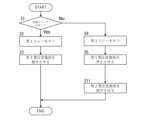
- FIG. 6 is a flowchart illustrating an example of control by the control unit in the second embodiment.
- An in-vehicle control device for use in an in-vehicle system including a high-voltage battery, a high-voltage load, and a low-voltage load, comprising: a relay provided between the high voltage battery and the high voltage load; A first voltage conversion unit provided between the relay and the low-voltage load; a second voltage conversion unit provided in parallel with the relay and the first voltage conversion unit; a control unit that controls the relay, the first voltage conversion unit, and the second voltage conversion unit, the first voltage conversion unit performs a first conversion operation of converting a voltage input from the high-voltage battery side through the relay into a low voltage lower than an output voltage from the high-voltage battery and outputting the low-voltage load side; the second voltage conversion unit performs a second conversion operation of converting a voltage input from the high-voltage battery side into the low-voltage and outputting the low-voltage load side;
- the control unit controls the relay to an on state while the vehicle is traveling, while causing the first voltage conversion unit to perform the first
- the vehicle control device (1) uses the second voltage conversion unit when the vehicle is parked, making it possible to avoid using the relay provided between the high-voltage battery and the high-voltage load. This makes it possible to suppress deterioration of the relay, thereby extending the service life of the relay.
- the in-vehicle control device of (2) is configured to make the output current when the power supply efficiency of the second voltage conversion unit is at its maximum smaller than the output current when the power supply efficiency of the first voltage conversion unit is at its maximum, making it easier to supply power appropriate to the operating state of the low-voltage load when the vehicle is moving and when the vehicle is parked.
- the first voltage conversion unit includes a first transformer that converts a voltage
- the second voltage conversion unit has a second transformer that converts a voltage
- the in-vehicle control device according to (2) wherein an outer shape of the second transformer is smaller than an outer shape of the first transformer.
- the in-vehicle control device (3) is configured such that the output current when the power supply efficiency of the second voltage conversion unit is at its maximum is smaller than the output current when the power supply efficiency of the first voltage conversion unit is at its maximum, so that the second voltage conversion unit can be made smaller than the first voltage conversion unit.
- the in-vehicle system includes a low-voltage battery; the low-voltage battery is capable of supplying power to the low-voltage load;
- the control unit adjusts the output voltage of the second voltage conversion unit so that power supply from the second voltage conversion unit to the low-voltage load is prioritized over power supply from the low-voltage battery to the low-voltage load.
- the vehicle control device can reduce the number of times the low-voltage battery is charged and discharged, slowing down the deterioration of the low-voltage battery.
- the vehicle control device can reliably isolate the inside and outside of the battery case using the first and second relays, making it easier to prevent the output voltage of the high-voltage battery from being exposed outside the battery case.
- the in-vehicle system 100 shown in Fig. 1 is a power supply system mounted on a vehicle.
- the in-vehicle system 100 includes a high-voltage battery 10 for high voltage, a battery case 30 that houses the high-voltage battery 10, a high-voltage load 12, a low-voltage battery 11, and a low-voltage load 13.
- the high-voltage load 12 operates with power supplied from the high-voltage battery 10.
- the low-voltage battery 11 outputs a voltage lower than the output voltage of the high-voltage battery 10.
- the in-vehicle control device 1 of the present disclosure is used in the in-vehicle system 100.
- the in-vehicle control device 1 includes a first relay 20 which is a relay, a second relay 24 which is a relay, a first voltage conversion unit 21, a second voltage conversion unit 22, and a control unit 23.
- the high-voltage battery 10 is an assembled battery configured by combining a plurality of unit cells, such as lithium-ion batteries or nickel-metal hydride batteries, in series, and outputs an output voltage of, for example, about 400 V.
- the high-voltage battery 10 is housed in a battery case 30.
- the battery case 30 is configured to cover the entire high-voltage battery 10.
- the battery case 30 is provided with a first terminal 30A and a second terminal 30B.
- a first conductive path 16 is electrically connected to the high-voltage side terminal of the high-voltage battery 10.
- connection objects preferably means a configuration in which the connection objects are connected in a mutually conductive state (a state in which current can flow) so that the potentials of both connection objects are equal.
- electrically connected may also mean a configuration in which the connection objects are connected in a state in which they can be conductive with an electrical component interposed between them.
- the high-voltage load 12 receives the output voltage of the high-voltage battery 10 as is via the first relay 20 described below.
- the high-voltage load 12 corresponds to, for example, a motor that drives the wheels of a vehicle.
- the high-voltage load 12 is a load that operates while the vehicle is traveling.
- the concept of the vehicle being in motion also includes a state in which the vehicle is temporarily stopped while traveling.
- the high-voltage load 12 is electrically connected to the first relay 20 via the second conductive path 17.
- the low-voltage battery 11 can be, for example, a lead-acid battery, or a configuration using the same type of single cells as the high-voltage battery 10 but with fewer cells connected in series compared to the high-voltage battery 10.
- the low-voltage battery 11 can output an output voltage of, for example, about 12 V.
- the low-voltage battery 11 is configured separately from the high-voltage battery 10.
- the low-voltage battery 11 is electrically connected to the first voltage conversion unit 21, which will be described later, via a third conductive path 18.
- the low-voltage load 13 includes a first low-voltage load 13A and a second low-voltage load 13B.
- the first low-voltage load 13A is, for example, a load that operates only while the vehicle is traveling.
- the first low-voltage load 13A corresponds to, for example, a sensor that operates while traveling to assist the driver when driving the vehicle.
- the second low-voltage load 13B is a load that operates not only while the vehicle is traveling but also while the vehicle is parked.
- the second low-voltage load 13B corresponds to, for example, an air conditioner compressor, a display disposed on the dashboard, an interior light, etc.
- the low-voltage load 13 is electrically connected to a third conductive path 18.
- the low-voltage load 13 can be supplied with power from the low-voltage battery 11.
- the low-voltage load 13 can also be supplied with power from the high-voltage battery 10 via a first relay 20 and a first voltage conversion unit 21, which will be described later.
- the second relay 24 is a so-called system sub-relay (SSR).
- SSR system sub-relay
- the operation of the second relay 24 is controlled by the control unit 23.
- the second relay 24 is switched between an on state and an off state by the control unit 23.
- the second relay 24 is in the on state, the first conductive path 16 and the fourth conductive path 19 are electrically connected via the second relay 24.
- the voltage of the high-voltage battery 10 applied via the first conductive path 16 is directly applied to the fourth conductive path 19.
- the second relay 24 is in the off state, the first conductive path 16 and the fourth conductive path 19 are disconnected.
- the second relay 24 is provided inside the battery case 30.
- the voltage applied from the first voltage conversion unit 21 to the third conductive path 18 is slightly higher than the charging voltage of the low-voltage battery 11 when it is fully charged.
- the step-down operation performed by the first voltage conversion unit 21 corresponds to an example of a first conversion operation.
- the first relay 20 is provided between the high-voltage battery 10 and the high-voltage load 12.
- the second voltage conversion unit 22 has a similar configuration to the first voltage conversion unit 21. As shown in FIG. 2, the second voltage conversion unit 22 has a second transformer 22A that has a function of converting voltage, and is a known isolated step-down DCDC converter capable of stepping down voltage. The outer shape of the second transformer 22A is smaller than that of the first transformer 21A.
- the second voltage conversion unit 22 has a configuration in which two switch elements 22B are connected in a half-bridge configuration. A MOSFET semiconductor switch or the like is used for the switch element 22B.
- the second voltage conversion unit 22 is a so-called LLC resonant type DCDC converter.
- the second voltage conversion unit 22 converts the voltage of the high-voltage battery 10 applied to the fourth conductive path 19 into a low voltage lower than the output voltage of the high-voltage battery 10, and performs a step-down operation to apply the low voltage to the third conductive path 18.
- the second voltage conversion unit 22 and the second relay 24 are electrically connected in series.
- the second voltage conversion unit 22 is provided outside the battery case 30. Therefore, the fourth conductive path 19 is configured to be pulled out from the battery case 30 to the outside of the battery case 30.
- the second terminal 30B of the battery case 30 is provided on the fourth conductive path 19. In other words, the second relay 24 is provided between the second terminal 30B and the high-voltage battery 10.
- the second relay 24 and the second voltage conversion unit 22 are provided in parallel with the first relay 20 and the first voltage conversion unit 21.
- the control unit 23 adjusts the output voltage of the second voltage conversion unit 22 so that the power supply from the second voltage conversion unit 22 to the low-voltage load 13 takes priority over the power supply from the low-voltage battery 11 to the low-voltage load 13. Specifically, the control unit 23 applies the output voltage of the second voltage conversion unit 22 to the third conductive path 18 at a voltage slightly higher than the charging voltage of the low-voltage battery 11 when fully charged.
- the step-down operation performed by the second voltage conversion unit 22 corresponds to an example of the second conversion operation.
- the second relay 24 is provided between the high-voltage battery 10 and the second voltage conversion unit 22.
- the first relay 20 and the second relay 24 are in the off state, the voltage of the high-voltage battery 10 is not applied to the second conductive path 17 and the fourth conductive path 19. Therefore, by turning off the first relay 20 and the second relay 24, it is possible to prevent the voltage of the high-voltage battery 10 from being exposed to the outside of the battery case 30.
- the output current P2 when the power supply efficiency of the second voltage conversion unit 22 (dotted line graph in FIG. 3) is at its maximum is set to be smaller than the output current P1 when the power supply efficiency of the first voltage conversion unit 21 (solid line graph in FIG. 3) is at its maximum.
- power supply efficiency is the ratio of power received by a load to the power output from the voltage conversion unit.
- the second voltage conversion unit 22 can supply power more efficiently to a load that consumes less power than the first voltage conversion unit 21.
- the first voltage conversion unit 21 can supply power more efficiently to a load that consumes more power than the second voltage conversion unit 22.
- the control unit 23 is configured as, for example, a microcomputer, and includes a CPU, a ROM, a RAM, a non-volatile memory, and the like.
- the control unit 23 is configured to receive, for example, a signal indicating that the vehicle is running (a signal indicating that the start switch is on) or a signal indicating that the vehicle is parked (a signal indicating that the start switch is off) from an external ECU (not shown).
- the control unit 23 is also configured to receive a signal requesting power supply to the second low-voltage load 13B from the external ECU.
- the control unit 23 has a function of operating either the first voltage conversion unit 21 or the second voltage conversion unit 22 based on this signal.
- the control unit 23 can control the first relay 20 and the second relay 24 to be individually switched between an on state and an off state based on a signal indicating that the vehicle is running (a signal indicating that the start switch is on) or a signal indicating that the vehicle is parked (a signal indicating that the start switch is off).
- the control unit 23 controls the first relay 20 to the on state and causes the first voltage conversion unit 21 to perform the first conversion operation. At this time, the control unit 23 keeps the second relay 24 in the off state and does not cause the second voltage conversion unit 22 to perform the second conversion operation.
- the control unit 23 controls the second relay 24 to the ON state and causes the second voltage conversion unit 22 to perform the second conversion operation. At this time, the control unit 23 keeps the first relay 20 in the OFF state and does not cause the first voltage conversion unit 21 to perform the first conversion operation. In this way, the control unit 23 controls the operations of the first relay 20, the second relay 24, the first voltage conversion unit 21, and the second voltage conversion unit 22.
- step S1 When a signal indicating that the start switch is on is input from the external ECU (Yes in step S1), the process proceeds to step S2, where the control unit 23 switches the first relay 20 to the on state.
- the start switch being on corresponds to an instruction to switch the first relay 20 on.
- the voltage of the high-voltage battery 10 is applied to the first voltage conversion unit 21.
- step S3 the control unit 23 operates the first voltage conversion unit 21.
- the first voltage conversion unit 21 applies a low voltage to the low-voltage battery 11 and the low-voltage load 13.
- the control unit 23 switches the second relay 24 to the off state, but does not operate the second voltage conversion unit 22.
- the process shown in FIG. 4 is terminated. In this way, the high-voltage load 12 and the low-voltage load 13 are supplied with power while the vehicle is running.
- step S6 the control unit 23 determines whether or not it is possible and necessary to supply power to the low-voltage load 13 via the second voltage conversion unit 22. Specifically, the control unit 23 determines whether or not a signal requesting power supply to the second low-voltage load 13B has been input from the external ECU.
- step S6 determines in step S6 that it is possible and necessary to supply power to the low-voltage load 13 via the second voltage conversion unit 22 (i.e., a signal requesting power supply to the second low-voltage load 13B has been input from the external ECU) (Yes in step S6)
- step S7 the control unit 23 switches the second relay 24 to the on state.
- step S8 the control unit 23 operates the second voltage conversion unit 22, and ends the process shown in FIG. 4. In this way, the second low-voltage load 13B is supplied with power and operates while the vehicle is parked.
- step S6 If the control unit 23 determines in step S6 that power supply to the low-voltage load 13 via the second voltage conversion unit 22 is possible but not necessary (i.e., a signal requesting power supply to the second low-voltage load 13B has not been input from the external ECU) (No in step S6), the process proceeds to step S9, where the control unit 23 switches the second relay 24 to the off state. Then, the process proceeds to step S10, where the control unit 23 stops the operation of the second voltage conversion unit 22 and ends the process shown in FIG. 4. At this time, since both the first relay 20 and the second relay 24 are turned off, the voltage of the high-voltage battery 10 is not exposed to the outside of the battery case 30.
- step S6 is suitable for performing vehicle maintenance or when the detected SOC of the high-voltage battery 10 is in an unexpected state, since the voltage of the high-voltage battery 10 is not exposed to the outside of the battery case 30.
- the vehicle control device 1 is used in a vehicle system 100 including a high-voltage battery 10, a high-voltage load 12, and a low-voltage load 13.
- the vehicle control device 1 includes a first relay 20, a first voltage conversion unit 21, a second voltage conversion unit 22, and a control unit 23.
- the first relay 20 is provided between the high-voltage battery 10 and the high-voltage load 12.
- the first voltage conversion unit 21 is provided between the first relay 20 and the low-voltage load 13.
- the second voltage conversion unit 22 is provided in parallel with the first relay 20 and the first voltage conversion unit 21.
- the control unit 23 controls the first relay 20, the first voltage conversion unit 21, and the second voltage conversion unit 22.
- the device includes a second relay 24 provided between the high-voltage battery 10 and the second voltage conversion unit 22, and a battery case 30 that houses the high-voltage battery 10, and the control unit 23 controls the second relay 24.
- the second relay 24 and the second voltage conversion unit 22 are provided in parallel with the first relay 20 and the first voltage conversion unit 21.
- the first relay 20 and the second relay 24 are provided inside the battery case 30.
- the in-vehicle control device 2 of the second embodiment is different from the first embodiment in that it does not include a second relay and that the second voltage conversion unit 22 is provided in the battery case 30, but is otherwise common to both embodiments.
- the same components as those in the first embodiment are denoted by the same reference numerals and detailed description will be omitted.
- the in-vehicle system 200 is a power supply system mounted on a vehicle.
- the first relay 20 is provided in the battery case 30 together with the second voltage conversion unit 22.
- the first voltage conversion unit 21 is provided outside the battery case 30.
- the second voltage conversion unit 22 converts the voltage of the high-voltage battery 10 applied to the first conductive path 16 into a low voltage lower than the output voltage of the high-voltage battery 10 and performs a step-down operation to apply a constant voltage to the third conductive path 18.
- the second voltage conversion unit 22 is housed in the battery case 30. Therefore, the third conductive path 18 electrically connected to the second voltage conversion unit 22 is configured to be pulled out from the battery case 30 to the outside of the battery case 30.
- the second terminal 30B of the battery case 30 is provided on the third conductive path 18.
- the second voltage conversion unit 22 is provided between the second terminal 30B and the high-voltage battery 10.
- the second voltage conversion unit 22 is provided in parallel with the first relay 20 and the first voltage conversion unit 21.
- Steps S1 to S5 execute the same processing as in embodiment 1. Specifically, when a signal indicating that the start switch is in the OFF state is input from the external ECU (No in step S1), the process proceeds to step S4. When the process proceeds to step S4, the control unit 23 switches the first relay 20 to the OFF state, and the process proceeds to step S5, where the control unit 23 stops the operation of the first voltage conversion unit 21.
- step S11 the control unit 23 operates the second voltage conversion unit 22.
- the second low-voltage load 13B is supplied with power and operates while the vehicle is parked.
- control unit may be housed in the battery box.
- the second voltage conversion unit in addition to reducing the external dimensions of the second transformer, it is also possible to reduce the scale of the water-cooling or air-cooling configuration, narrow the width of the wiring pattern on the board, reduce the size of the heat dissipation sink, and reduce the size of the housing that houses the second voltage conversion unit.
- First relay (relay) 21 ...First voltage conversion unit 21A...First transformer 21B...Switch element 22...Second voltage conversion unit 22A...Second transformer 22B...Switch element 23...Control unit 24...Second relay 30...Battery case 30A...First terminal 30B...Second terminal 100, 200...In-vehicle system P1...Output current when the power supply efficiency of the first voltage conversion unit is maximized P2...Output current when the power supply efficiency of the second voltage conversion unit is maximized
Landscapes
- Engineering & Computer Science (AREA)
- Power Engineering (AREA)
- Transportation (AREA)
- Mechanical Engineering (AREA)
- Life Sciences & Earth Sciences (AREA)
- Sustainable Development (AREA)
- Sustainable Energy (AREA)
- Charge And Discharge Circuits For Batteries Or The Like (AREA)
- Electric Propulsion And Braking For Vehicles (AREA)
Abstract
Description
高圧バッテリと、高圧負荷と、低圧負荷と、を備える車載システムに用いられる車載用制御装置であって、
前記高圧バッテリと前記高圧負荷との間に設けられるリレーと、
前記リレーと前記低圧負荷との間に設けられる第1電圧変換部と、
前記リレー及び前記第1電圧変換部に対して並列に設けられる第2電圧変換部と、
前記リレー、前記第1電圧変換部、及び前記第2電圧変換部を制御する制御部と、を備え、
前記第1電圧変換部は、前記高圧バッテリ側から前記リレーを介して入力される電圧を前記高圧バッテリからの出力電圧よりも低い低電圧に変換して前記低圧負荷側に出力する第1変換動作を行い、
前記第2電圧変換部は、前記高圧バッテリ側から入力される電圧を前記低電圧に変換して前記低圧負荷側に出力する第2変換動作を行い、
前記制御部は、車両の走行中において前記リレーをオン状態に制御しつつ前記第1電圧変換部に前記第1変換動作を行わせ、前記車両の駐車中において前記第2電圧変換部に前記第2変換動作を行わせる。
以下では、本開示の実施形態が列記されて例示される。
前記高圧バッテリと前記高圧負荷との間に設けられるリレーと、
前記リレーと前記低圧負荷との間に設けられる第1電圧変換部と、
前記リレー及び前記第1電圧変換部に対して並列に設けられる第2電圧変換部と、
前記リレー、前記第1電圧変換部、及び前記第2電圧変換部を制御する制御部と、を備え、
前記第1電圧変換部は、前記高圧バッテリ側から前記リレーを介して入力される電圧を前記高圧バッテリからの出力電圧よりも低い低電圧に変換して前記低圧負荷側に出力する第1変換動作を行い、
前記第2電圧変換部は、前記高圧バッテリ側から入力される電圧を前記低電圧に変換して前記低圧負荷側に出力する第2変換動作を行い、
前記制御部は、車両の走行中において前記リレーをオン状態に制御しつつ前記第1電圧変換部に前記第1変換動作を行わせ、前記車両の駐車中において前記第2電圧変換部に前記第2変換動作を行わせる、車載用制御装置。
前記第2電圧変換部は、電圧を変換する第2トランスを有し、
前記第2トランスの外形は、前記第1トランスの外形よりも小さい、(2)に記載の車載用制御装置。
前記低圧バッテリは、前記低圧負荷に電力供給可能とされ、
前記制御部は、前記第2電圧変換部から前記低圧負荷への電力供給が、前記低圧バッテリからの前記低圧負荷への電力供給よりも優先されるように前記第2電圧変換部の出力電圧を調整する、(1)又は(2)に記載の車載用制御装置。
更に、前記高圧バッテリと前記第2電圧変換部との間に設けられる第2リレーと、
前記高圧バッテリを収容するバッテリケースと、を備え、
前記制御部は、前記第2リレーを制御し、
前記第2リレー及び前記第2電圧変換部は、前記第1リレー及び前記第1電圧変換部に対して並列に設けられ、
前記第1リレー及び前記第2リレーは、前記バッテリケース内に設けられている、(1)又は(2)に記載の車載用制御装置。
前記リレー及び前記第2電圧変換部は、前記バッテリケース内に設けられている、(1)又は(2)に記載の車載用制御装置。
以下、本開示を具体化した実施形態1について説明する。
図1に示す車載システム100は、車両に搭載される電源システムである。車載システム100は、高圧用の高圧バッテリ10と、高圧バッテリ10を収容するバッテリケース30と、高圧負荷12と、低圧バッテリ11と、低圧負荷13と、を備える。高圧負荷12は、高圧バッテリ10から供給される電力によって動作する。低圧バッテリ11は、高圧バッテリ10の出力電圧よりも低い電圧を出力する。本開示の車載用制御装置1は、車載システム100に用いられる。車載用制御装置1は、リレーである第1リレー20、リレーである第2リレー24、第1電圧変換部21、第2電圧変換部22、及び制御部23を有している。
高圧バッテリ10は、例えば、リチウムイオン電池又はニッケル水素電池等の単電池を複数直列に組み合わせて構成される組電池であり、例えば400V程度の出力電圧を出力する。高圧バッテリ10は、バッテリケース30に収容されている。バッテリケース30は、高圧バッテリ10の全体を覆うように構成されている。バッテリケース30には、第1端子30Aと、第2端子30Bと、が設けられている。高圧バッテリ10の高電圧側の端子には、第1導電路16が電気的に接続されている。
第1リレー20は、所謂、システムメインリレー(SMR)である。第1リレー20は、後述する制御部23によってその動作が制御される構成とされている。第1リレー20は、制御部23によって、オン状態と、オフ状態とに切り替えられる。第1リレー20がオン状態のときには、第1リレー20を介して第1導電路16と第2導電路17とが導通する。これにより、第1導電路16を介して印加された高圧バッテリ10の電圧は、そのまま第2導電路17に付与される。第1リレー20がオフ状態のときには、第1導電路16と第2導電路17とが遮断される。このとき、第1導電路16を介して印加された高圧バッテリ10の電圧は、第2導電路17に付与されない。第1リレー20は、バッテリケース30内に設けられている。第2導電路17には、高圧負荷12が電気的に接続されている。
次に、制御部23によって実行される制御の一例について、図4等を参照しつつ説明する。
車載用制御装置1は、高圧バッテリ10と、高圧負荷12と、低圧負荷13と、を備える車載システム100に用いられる。車載用制御装置1は、第1リレー20と、第1電圧変換部21と、第2電圧変換部22と、制御部23と、を備えている。第1リレー20は、高圧バッテリ10と高圧負荷12との間に設けられる。第1電圧変換部21は、第1リレー20と低圧負荷13との間に設けられる。第2電圧変換部22は、第1リレー20及び第1電圧変換部21に対して並列に設けられる。制御部23は、第1リレー20、第1電圧変換部21、及び第2電圧変換部22を制御する。第1電圧変換部21は、高圧バッテリ10側から第1リレー20を介して入力される電圧を高圧バッテリ10からの出力電圧よりも低い低電圧に変換して低圧負荷13側に出力する第1変換動作を行う。第2電圧変換部22は、高圧バッテリ10側から入力される電圧を低電圧に変換して低圧負荷13側に出力する第2変換動作を行う。制御部23は、車両の走行中において第1リレー20をオン状態に制御しつつ第1電圧変換部21に第1変換動作を行わせ、車両の駐車中において第2電圧変換部22に第2変換動作を行わせる。
図5に示すように、実施形態2の車載用制御装置2は、第2リレーを備えない点、第2電圧変換部22がバッテリケース30に設けられている点等が実施形態1とは異なり、その他の点で共通する。実施形態2では、実施形態1と同じ構成については同じ符号を付し、詳しい説明を省略する。車載システム200は、車両に搭載される電源システムである。
次に、制御部23によって実行される制御の一例について、図6等を参照しつつ説明する。
今回開示された実施の形態は全ての点で例示であって制限的なものではないと考えられるべきである。本発明の範囲は、今回開示された実施の形態に限定されるものではなく、請求の範囲によって示され、請求の範囲と均等の意味及び範囲内での全ての変更が含まれることが意図される。
10…高圧バッテリ
11…低圧バッテリ
12…高圧負荷
13…低圧負荷
13A…第1低圧負荷
13B…第2低圧負荷
16…第1導電路
17…第2導電路
18…第3導電路
19…第4導電路
20…第1リレー(リレー)
21…第1電圧変換部
21A…第1トランス
21B…スイッチ素子
22…第2電圧変換部
22A…第2トランス
22B…スイッチ素子
23…制御部
24…第2リレー
30…バッテリケース
30A…第1端子
30B…第2端子
100,200…車載システム
P1…第1電圧変換部の給電効率が最大となるときの出力電流
P2…第2電圧変換部の給電効率が最大となるときの出力電流
Claims (6)
- 高圧バッテリと、高圧負荷と、低圧負荷と、を備える車載システムに用いられる車載用制御装置であって、
前記高圧バッテリと前記高圧負荷との間に設けられるリレーと、
前記リレーと前記低圧負荷との間に設けられる第1電圧変換部と、
前記リレー及び前記第1電圧変換部に対して並列に設けられる第2電圧変換部と、
前記リレー、前記第1電圧変換部、及び前記第2電圧変換部を制御する制御部と、を備え、
前記第1電圧変換部は、前記高圧バッテリ側から前記リレーを介して入力される電圧を前記高圧バッテリからの出力電圧よりも低い低電圧に変換して前記低圧負荷側に出力する第1変換動作を行い、
前記第2電圧変換部は、前記高圧バッテリ側から入力される電圧を前記低電圧に変換して前記低圧負荷側に出力する第2変換動作を行い、
前記制御部は、車両の走行中において前記リレーをオン状態に制御しつつ前記第1電圧変換部に前記第1変換動作を行わせ、前記車両の駐車中において前記第2電圧変換部に前記第2変換動作を行わせる、車載用制御装置。 - 前記第2電圧変換部の給電効率が最大となるときの出力電流は、前記第1電圧変換部の給電効率が最大となるときの出力電流よりも小さい、請求項1に記載の車載用制御装置。
- 前記第1電圧変換部は、電圧を変換する第1トランスを有し、
前記第2電圧変換部は、電圧を変換する第2トランスを有し、
前記第2トランスの外形は、前記第1トランスの外形よりも小さい、請求項2に記載の車載用制御装置。 - 前記車載システムは、低圧バッテリを備え、
前記低圧バッテリは、前記低圧負荷に電力供給可能とされ、
前記制御部は、前記第2電圧変換部から前記低圧負荷への電力供給が、前記低圧バッテリからの前記低圧負荷への電力供給よりも優先されるように前記第2電圧変換部の出力電圧を調整する、請求項1又は請求項2に記載の車載用制御装置。 - 前記リレーは、第1リレーであり、
更に、前記高圧バッテリと前記第2電圧変換部との間に設けられる第2リレーと、
前記高圧バッテリを収容するバッテリケースと、を備え、
前記制御部は、前記第2リレーを制御し、
前記第2リレー及び前記第2電圧変換部は、前記第1リレー及び前記第1電圧変換部に対して並列に設けられ、
前記第1リレー及び前記第2リレーは、前記バッテリケース内に設けられている、請求項1又は請求項2に記載の車載用制御装置。 - 更に、前記高圧バッテリを収容するバッテリケースを備え、
前記リレー及び前記第2電圧変換部は、前記バッテリケース内に設けられている、請求項1又は請求項2に記載の車載用制御装置。
Priority Applications (3)
| Application Number | Priority Date | Filing Date | Title |
|---|---|---|---|
| PCT/JP2023/011700 WO2024201550A1 (ja) | 2023-03-24 | 2023-03-24 | 車載用制御装置 |
| CN202380078920.2A CN120188370A (zh) | 2023-03-24 | 2023-03-24 | 车载用控制装置 |
| JP2024501104A JP7560808B1 (ja) | 2023-03-24 | 2023-03-24 | 車載用制御装置 |
Applications Claiming Priority (1)
| Application Number | Priority Date | Filing Date | Title |
|---|---|---|---|
| PCT/JP2023/011700 WO2024201550A1 (ja) | 2023-03-24 | 2023-03-24 | 車載用制御装置 |
Publications (1)
| Publication Number | Publication Date |
|---|---|
| WO2024201550A1 true WO2024201550A1 (ja) | 2024-10-03 |
Family
ID=92900387
Family Applications (1)
| Application Number | Title | Priority Date | Filing Date |
|---|---|---|---|
| PCT/JP2023/011700 Ceased WO2024201550A1 (ja) | 2023-03-24 | 2023-03-24 | 車載用制御装置 |
Country Status (3)
| Country | Link |
|---|---|
| JP (1) | JP7560808B1 (ja) |
| CN (1) | CN120188370A (ja) |
| WO (1) | WO2024201550A1 (ja) |
Citations (2)
| Publication number | Priority date | Publication date | Assignee | Title |
|---|---|---|---|---|
| JP2012240593A (ja) * | 2011-05-23 | 2012-12-10 | Mazda Motor Corp | 車両の電源制御装置 |
| WO2022009984A1 (ja) * | 2020-07-10 | 2022-01-13 | 株式会社オートネットワーク技術研究所 | 変換装置 |
-
2023
- 2023-03-24 CN CN202380078920.2A patent/CN120188370A/zh active Pending
- 2023-03-24 JP JP2024501104A patent/JP7560808B1/ja active Active
- 2023-03-24 WO PCT/JP2023/011700 patent/WO2024201550A1/ja not_active Ceased
Patent Citations (2)
| Publication number | Priority date | Publication date | Assignee | Title |
|---|---|---|---|---|
| JP2012240593A (ja) * | 2011-05-23 | 2012-12-10 | Mazda Motor Corp | 車両の電源制御装置 |
| WO2022009984A1 (ja) * | 2020-07-10 | 2022-01-13 | 株式会社オートネットワーク技術研究所 | 変換装置 |
Also Published As
| Publication number | Publication date |
|---|---|
| JP7560808B1 (ja) | 2024-10-03 |
| JPWO2024201550A1 (ja) | 2024-10-03 |
| CN120188370A (zh) | 2025-06-20 |
Similar Documents
| Publication | Publication Date | Title |
|---|---|---|
| US6930404B1 (en) | Power supply for an automotive vehicle | |
| US9809126B2 (en) | Vehicle-mounted power source apparatus | |
| US10960775B2 (en) | DC/DC conversion unit | |
| US20150298631A1 (en) | Electric transportation means, associated method and associated rechargeable battery | |
| US9475439B2 (en) | Battery system for micro-hybrid vehicles comprising high-efficiency consumers | |
| JP5387383B2 (ja) | 車載電源装置 | |
| US10933762B2 (en) | DC/DC conversion unit | |
| WO2011102458A1 (ja) | 電源システム、及び、電気自動車 | |
| JP2022105313A (ja) | バッテリー制御方法およびその方法を提供するバッテリーシステム | |
| JP2013150524A (ja) | 電気自動車 | |
| WO2019244606A1 (ja) | 車両用電源装置 | |
| JP2003095039A (ja) | 自動車用電源システム | |
| WO2012067116A1 (ja) | 電源供給制御装置 | |
| US11155221B2 (en) | Power supply device for vehicle | |
| JP7560808B1 (ja) | 車載用制御装置 | |
| KR102356756B1 (ko) | 친환경 차량의 비상 전력 공급 장치 | |
| US11894714B2 (en) | Power source system | |
| JP2026001855A (ja) | 電源装置 | |
| JP7568690B2 (ja) | 車両用電気接続箱 | |
| US20260081432A1 (en) | Vehicle power supply device | |
| JP7622593B2 (ja) | ソーラー充電制御システム、方法、及び車両 | |
| CN120073951A (zh) | 实现桥臂复用的多合一供电装置、动力总成和电动车辆 | |
| CN120073950A (zh) | 实现桥臂复用的多合一供电装置、动力总成和电动车辆 | |
| WO2024134746A1 (ja) | 切替システムおよび切替装置 | |
| JP2019030050A (ja) | 電源システム |
Legal Events
| Date | Code | Title | Description |
|---|---|---|---|
| WWE | Wipo information: entry into national phase |
Ref document number: 2024501104 Country of ref document: JP |
|
| 121 | Ep: the epo has been informed by wipo that ep was designated in this application |
Ref document number: 23930192 Country of ref document: EP Kind code of ref document: A1 |
|
| WWE | Wipo information: entry into national phase |
Ref document number: 202380078920.2 Country of ref document: CN |
|
| WWP | Wipo information: published in national office |
Ref document number: 202380078920.2 Country of ref document: CN |
|
| NENP | Non-entry into the national phase |
Ref country code: DE |
|
| 122 | Ep: pct application non-entry in european phase |
Ref document number: 23930192 Country of ref document: EP Kind code of ref document: A1 |