WO2024201265A1 - 二次電池 - Google Patents
二次電池 Download PDFInfo
- Publication number
- WO2024201265A1 WO2024201265A1 PCT/IB2024/052822 IB2024052822W WO2024201265A1 WO 2024201265 A1 WO2024201265 A1 WO 2024201265A1 IB 2024052822 W IB2024052822 W IB 2024052822W WO 2024201265 A1 WO2024201265 A1 WO 2024201265A1
- Authority
- WO
- WIPO (PCT)
- Prior art keywords
- negative electrode
- active material
- secondary battery
- electrode active
- coating layer
- Prior art date
- Legal status (The legal status is an assumption and is not a legal conclusion. Google has not performed a legal analysis and makes no representation as to the accuracy of the status listed.)
- Ceased
Links
Images














Classifications
-
- H—ELECTRICITY
- H01—ELECTRIC ELEMENTS
- H01M—PROCESSES OR MEANS, e.g. BATTERIES, FOR THE DIRECT CONVERSION OF CHEMICAL ENERGY INTO ELECTRICAL ENERGY
- H01M10/00—Secondary cells; Manufacture thereof
- H01M10/05—Accumulators with non-aqueous electrolyte
- H01M10/052—Li-accumulators
-
- H—ELECTRICITY
- H01—ELECTRIC ELEMENTS
- H01M—PROCESSES OR MEANS, e.g. BATTERIES, FOR THE DIRECT CONVERSION OF CHEMICAL ENERGY INTO ELECTRICAL ENERGY
- H01M10/00—Secondary cells; Manufacture thereof
- H01M10/05—Accumulators with non-aqueous electrolyte
- H01M10/056—Accumulators with non-aqueous electrolyte characterised by the materials used as electrolytes, e.g. mixed inorganic/organic electrolytes
- H01M10/0564—Accumulators with non-aqueous electrolyte characterised by the materials used as electrolytes, e.g. mixed inorganic/organic electrolytes the electrolyte being constituted of organic materials only
- H01M10/0566—Liquid materials
- H01M10/0569—Liquid materials characterised by the solvents
-
- H—ELECTRICITY
- H01—ELECTRIC ELEMENTS
- H01M—PROCESSES OR MEANS, e.g. BATTERIES, FOR THE DIRECT CONVERSION OF CHEMICAL ENERGY INTO ELECTRICAL ENERGY
- H01M4/00—Electrodes
- H01M4/02—Electrodes composed of, or comprising, active material
- H01M4/13—Electrodes for accumulators with non-aqueous electrolyte, e.g. for lithium-accumulators; Processes of manufacture thereof
-
- H—ELECTRICITY
- H01—ELECTRIC ELEMENTS
- H01M—PROCESSES OR MEANS, e.g. BATTERIES, FOR THE DIRECT CONVERSION OF CHEMICAL ENERGY INTO ELECTRICAL ENERGY
- H01M4/00—Electrodes
- H01M4/02—Electrodes composed of, or comprising, active material
- H01M4/13—Electrodes for accumulators with non-aqueous electrolyte, e.g. for lithium-accumulators; Processes of manufacture thereof
- H01M4/134—Electrodes based on metals, Si or alloys
-
- Y—GENERAL TAGGING OF NEW TECHNOLOGICAL DEVELOPMENTS; GENERAL TAGGING OF CROSS-SECTIONAL TECHNOLOGIES SPANNING OVER SEVERAL SECTIONS OF THE IPC; TECHNICAL SUBJECTS COVERED BY FORMER USPC CROSS-REFERENCE ART COLLECTIONS [XRACs] AND DIGESTS
- Y02—TECHNOLOGIES OR APPLICATIONS FOR MITIGATION OR ADAPTATION AGAINST CLIMATE CHANGE
- Y02E—REDUCTION OF GREENHOUSE GAS [GHG] EMISSIONS, RELATED TO ENERGY GENERATION, TRANSMISSION OR DISTRIBUTION
- Y02E60/00—Enabling technologies; Technologies with a potential or indirect contribution to GHG emissions mitigation
- Y02E60/10—Energy storage using batteries
Definitions
- One aspect of the present invention relates to a secondary battery and a method for producing the same.
- One aspect of the present invention relates to an object, a method, or a manufacturing method. Alternatively, the present invention relates to a process, a machine, a manufacture, or a composition of matter. One aspect of the present invention relates to a semiconductor device, a display device, a light-emitting device, a power storage device, a lighting device, an electronic device, a vehicle, or a manufacturing method thereof.
- electronic devices refer to devices that have a power storage device in general, and electro-optical devices that have a power storage device, information terminal devices that have a power storage device, etc. are all electronic devices.
- energy storage device refers to elements and devices in general that have a power storage function, and includes, for example, energy storage devices such as lithium ion secondary batteries (also called secondary batteries), lithium ion capacitors, and electric double layer capacitors.
- energy storage devices such as lithium ion secondary batteries (also called secondary batteries), lithium ion capacitors, and electric double layer capacitors.
- a lithium-ion secondary battery has at least a positive electrode, a negative electrode, and an electrolyte.
- lithium ions are released from the positive electrode and inserted into the negative electrode.
- lithium ions are released from the negative electrode and inserted into the positive electrode.
- the positive electrode and negative electrode each have an active material (positive electrode active material, negative electrode active material).
- An active material is a substance involved in the insertion and removal of ions (lithium ions), which act as carriers.
- metallic lithium, graphite, silicon, etc. have the preferred characteristics of low redox potential and high specific capacity per unit volume and unit weight.
- metallic lithium when metallic lithium is used as the negative electrode active material, lithium may be precipitated in a dendritic (whisker-like) form on the metallic lithium during charging. This dendritic precipitation may penetrate the separator and short-circuit with the positive electrode, causing the lithium-ion secondary battery to catch fire. Lithium precipitated in a dendritic form is also metallic lithium.
- graphite, silicon, etc. are used as the negative electrode active material, lithium may be precipitated in a dendritic form on the negative electrode active material when charging at low temperatures or with an excessively large charging current.
- Problems caused by lithium precipitated in a dendritic form include not only short circuits inside the secondary battery, but also separation of the lithium precipitated in a dendritic form at the base (the area close to the negative electrode current collector) during discharge and separation from the negative electrode (also called dead lithium). In this case, the lithium that can be exchanged between the positive and negative electrodes of the secondary battery is damaged, resulting in a decrease in discharge capacity.
- Patent Document 1 proposes a method for preventing lithium from precipitating in the form of dendrites.
- CNTs carbon nanotubes
- One aspect of the present invention has an objective to suppress the precipitation of lithium in a dendritic form at a negative electrode during charging. Another objective is to provide a lithium ion secondary battery having good cycle characteristics. Another objective is to provide a secondary battery having a large capacity per unit mass or unit volume. Alternatively, one aspect of the present invention has an objective to provide a novel negative electrode, a novel secondary battery, a novel power storage device, a novel method for manufacturing a negative electrode, a novel method for manufacturing a secondary battery, or a novel method for manufacturing a power storage device.
- One aspect of the present invention aims to achieve good insertion and desorption of lithium ions in the negative electrode. Another aim is to suppress decomposition of the electrolyte in the negative electrode. Another aim is to provide a lithium ion battery that can be charged and discharged over a wide temperature range, including below freezing.
- One aspect of the present invention is a secondary battery having a negative electrode, an electrolyte, and a separator, in which the negative electrode has a negative electrode active material and a coating layer that covers at least a portion of the negative electrode active material, the coating layer has a region in contact with the separator and a region in contact with the electrolyte, and the electrolyte has a fluorinated cyclic carbonate and a fluorinated chain carbonate.
- one aspect of the present invention is a secondary battery having a negative electrode, an electrolyte, and a separator, in which the negative electrode has a negative electrode active material and a coating layer that covers at least a portion of the negative electrode active material, the coating layer has a region in contact with the separator and a region in contact with the electrolyte, the coating layer has a material containing titanium, and the electrolyte has a fluorinated cyclic carbonate and a fluorinated chain carbonate.
- one aspect of the present invention is a secondary battery having a negative electrode, an electrolyte, and a separator, in which the negative electrode has a negative electrode active material and a coating layer that covers at least a portion of the negative electrode active material, the coating layer has a region in contact with the separator and a region in contact with the electrolyte, the coating layer has metallic titanium, and the electrolyte has a fluorinated cyclic carbonate and a fluorinated chain carbonate.
- one aspect of the present invention is a secondary battery having a negative electrode, an electrolyte, and a separator, in which the negative electrode has a negative electrode active material and a coating layer that covers at least a portion of the negative electrode active material, the coating layer has a region in contact with the separator and a region in contact with the electrolyte, the coating layer has titanium oxide, and the electrolyte has a fluorinated cyclic carbonate and a fluorinated chain carbonate.
- the negative electrode active material contains metallic lithium.
- the negative electrode active material contains silicon.
- the fluorinated cyclic carbonate has fluoroethylene carbonate, and the fluorinated chain carbonate has methyl trifluoropropionate.
- the fluorinated cyclic carbonate has fluoroethylene carbonate, and the fluorinated chain carbonate has methyl trifluoropropionate.
- one aspect of the present invention is a secondary battery having a negative electrode and an electrolyte, in which the negative electrode has a negative electrode current collector, a negative electrode active material layer on the negative electrode current collector, and a coating layer on the negative electrode active material layer, the negative electrode active material layer has metallic lithium, the coating layer has metallic titanium, and the electrolyte has fluoroethylene carbonate and methyl trifluoropropionate.
- One aspect of the present invention is a secondary battery having a negative electrode and an electrolyte, in which the negative electrode has a negative electrode current collector, a negative electrode active material layer on the negative electrode current collector, and a coating layer on the negative electrode active material layer, the negative electrode active material layer has silicon, the coating layer has metallic titanium, and the electrolyte has fluoroethylene carbonate and methyl trifluoropropionate.
- the thickness of the coating layer is 1 nm or more and 50 nm or less.
- One aspect of the present invention can suppress the precipitation of lithium in a dendritic form at the negative electrode during charging.
- a lithium ion secondary battery having good cycle characteristics can be provided.
- a secondary battery having a large capacity per unit mass and volume can be provided.
- one aspect of the present invention can provide a novel negative electrode, a novel secondary battery, a novel power storage device, a novel method for manufacturing a negative electrode, a novel method for manufacturing a secondary battery, or a novel method for manufacturing a power storage device.
- One aspect of the present invention allows for good insertion and removal of lithium ions in the negative electrode. It also makes it possible to suppress decomposition of the electrolyte in the negative electrode. It also makes it possible to provide a lithium ion battery that can be charged and discharged over a wide temperature range, including below freezing.
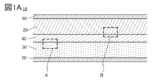
- FIG. 1A and 1B are schematic cross-sectional views of a secondary battery.
- 2A to 2D are schematic cross-sectional views of the negative electrode.
- 3A to 3C are schematic cross-sectional views of a negative electrode and a separator.
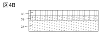
- 4A to 4C are schematic cross-sectional views of the negative electrode.
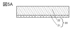
- 5A to 5C are schematic cross-sectional views of the positive electrode.
- FIG. 6 is a diagram showing the external appearance of the secondary battery.
- 7A to 7C are diagrams illustrating a method for manufacturing a secondary battery.
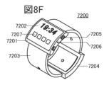
- 8A to 8H are diagrams illustrating an example of an electronic device.
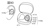
- 9A to 9D are diagrams illustrating an example of an electronic device.
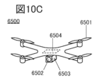
- 10A to 10C are diagrams illustrating an example of an electronic device.
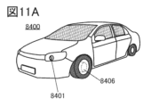
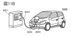
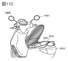
- 11A to 11C are diagrams illustrating an example of a vehicle.
- each component such as the positive electrode, negative electrode, active material layer, separator, and exterior body
- each component is not necessarily limited to its size, and the relative sizes of each component are not necessarily limited.
- ordinal numbers such as first, second, third, etc. are used for convenience and do not indicate the order of the steps, or the hierarchical relationship between steps. Therefore, for example, “first” can be appropriately replaced with “second” or “third” to explain the invention. In addition, the ordinal numbers described in this specification and the ordinal numbers used to identify an aspect of the present invention may not match.
- Fig. 1A is a schematic diagram illustrating a part of a cross section of a secondary battery 10 according to one embodiment of the present invention.
- Fig. 1B is an enlarged view illustrating a configuration example of an area A surrounded by a dashed line in Fig. 1A.
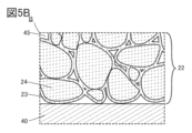
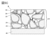
- Figs. 5B and 5C are enlarged views illustrating a configuration example of an area B surrounded by a dashed line in Fig. 1A.
- the secondary battery 10 has a positive electrode 20, a negative electrode 30, a separator 40, and an exterior body 50.
- the positive electrode 20, the negative electrode 30, and the separator 40 are located inside the secondary battery 10 covered with the exterior body 50.
- the positive electrode 20 and the negative electrode 30 have an overlapping area via the separator 40.
- the secondary battery 10 has an electrolyte inside the secondary battery 10 covered with the exterior body 50.
- the negative electrode 30 and electrolyte 45 of one embodiment of the present invention will be described with reference to FIG. 1B.
- the negative electrode 30 has a coating layer 33 and a negative electrode active material 34.
- the separator 40 has voids, and has an electrolyte 45 in the voids.
- the electrolyte has lithium ions.
- the voids in the separator 40 extend three-dimensionally inside the separator 40. Note that in the drawings other than FIG. 1B, the voids in the separator 40 are omitted.
- the negative electrode active material 34 has a coating layer 33 on its surface, and the coating layer 33 has a region in contact with the separator 40 and a region in contact with the electrolyte 45 .
- the coating layer 33 has a function of allowing lithium ions contained in the electrolyte 45 to permeate, and during charging of the secondary battery 10, as indicated by arrow D1 in Fig. 1B, lithium ions move from the electrolyte 45 contained in the voids of the separator 40 through the coating layer 33 to the negative electrode active material 34. During discharging of the secondary battery 10, lithium ions move from the negative electrode active material 34 through the coating layer 33 to the electrolyte 45 contained in the voids of the separator 40, as indicated by arrow D2 in Fig. 1B.
- the negative electrode active material 34 can insert lithium through the coating layer 33.
- the flow of lithium can be dispersed by moving through the coating layer 33.
- localized precipitation of lithium on the surface of the negative electrode active material 34 it is possible to suppress localized precipitation of lithium on the surface of the negative electrode active material 34.
- localized precipitation of lithium on the negative electrode is the cause of dendritic precipitation of lithium.
- the secondary battery 10 of one embodiment of the present invention can suppress dendritic precipitation of lithium by having the coating layer 33 on the surface of the negative electrode active material 34.
- the negative electrode active material 34 can desorb lithium through the coating layer 33. In such a configuration, it is considered that the flow of lithium can be dispersed by moving through the coating layer 33.
- Anode active materials such as silicon and tin that form alloys with lithium are known to undergo large volume changes during charging and discharging. Therefore, when lithium is released from the anode active material during discharging, it is released from the surface side of the anode active material, causing the volume of the anode active material to shrink from the surface side, which may cause the anode active material to crack.
- the secondary battery 10 of one embodiment of the present invention lithium released from the negative electrode active material 34 is not released directly into the electrolyte 45, but is released through the coating layer 33 into the electrolyte 45. Therefore, by having the coating layer 33, it is possible that the lithium released from the negative electrode active material 34 is dispersed.
- the coating layer 33 may have the function of maintaining the shape of the negative electrode active material 34. In other words, by having the coating layer 33 on the surface of the negative electrode active material 34, the secondary battery 10 of one embodiment of the present invention may be able to suppress cracking of the negative electrode active material 34.
- the negative electrode active material 34 has a coating layer 33.
- the coating layer 33 is preferably provided on the entire surface of the negative electrode active material 34, but is not necessarily required to be provided on the entire surface of the negative electrode active material 34. It is preferable that the coating layer 33 is provided on at least a part of the surface of the negative electrode active material 34.
- the coating layer 33 is preferably provided on 50% or more of the surface of the negative electrode active material 34, more preferably on 60% or more, more preferably on 70% or more, more preferably on 80% or more, more preferably on 90% or more, and more preferably on 95% or more.
- the coating layer 33 may be provided so as to cover the entire surface of the negative electrode active material 34, or may be provided in an island shape on the surface of the negative electrode active material 34.
- the coating layer 33 may also have a region where the surface of the negative electrode active material 34 and the electrolyte 45 are in contact with each other.
- a conductor also called a conductive material
- a semiconducting material can be used for the coating layer 33.
- a material containing titanium can be used for the coating layer 33.
- a material containing titanium refers to titanium and titanium compounds.
- An example of a titanium compound is titanium oxide.
- titanium, which is a metal is sometimes explicitly called metallic titanium.
- lithium can pass through the crystal grain boundaries of metallic titanium.
- the presence or absence of metallic titanium can be analyzed, for example, by XPS (X-ray photoelectron spectroscopy), and if metallic titanium is present, an energy peak can be confirmed at around 454 eV.
- XPS X-ray photoelectron spectroscopy
- a material containing ruthenium can be used as the coating layer 33.
- a material containing ruthenium refers to ruthenium and ruthenium compounds.
- An example of a ruthenium compound is ruthenium oxide.
- the thickness of the coating layer 33 can be from 1 nm to 10 ⁇ m, preferably from 1 nm to 1 ⁇ m, more preferably from 1 nm to 100 nm, more preferably from 1 nm to 50 nm, more preferably from 1 nm to 40 nm, more preferably from 1 nm to 30 nm, more preferably from 1 nm to 20 nm, more preferably from 1 nm to 10 nm, more preferably from 1 nm to 5 nm, and more preferably from 1 nm to 2 nm.
- lithium can be suitably inserted and removed from the negative electrode active material 34.
- a liquid electrolyte (also referred to as an electrolyte solution) containing an organic solvent and a lithium salt dissolved in the organic solvent can be used.
- the battery of one embodiment of the present invention contains at least the above-mentioned negative electrode 30 and electrolyte 45, and thus can smoothly insert and extract lithium ions in the negative electrode active material 34.
- a battery that can be charged and discharged over a wide temperature range, including below freezing, can be realized.
- the electrolyte having an organic solvent and a lithium salt that can be used in the battery of one embodiment of the present invention is described below.
- the organic solvent contained in the electrolyte described in this embodiment may include a fluorinated cyclic carbonate (sometimes referred to as a fluorinated cyclic carbonate) or a fluorinated chain carbonate (sometimes referred to as a fluorinated chain carbonate). Furthermore, the organic solvent preferably includes both a fluorinated cyclic carbonate and a fluorinated chain carbonate. Both the fluorinated cyclic carbonate and the fluorinated chain carbonate have a substituent that exhibits electron-withdrawing properties, and the solvation energy of lithium ions is lower than that of an organic compound that does not have a substituent that exhibits electron-withdrawing properties.
- both the fluorinated cyclic carbonate and the fluorinated chain carbonate are suitable as organic solvents.
- carbonate refers to a compound having at least one carbonate ester in its molecular structure, and includes cyclic carbonates and chain carbonates unless otherwise specified.
- chain includes both linear and branched chains.
- Fluoroethylene carbonate also referred to as fluorinated ethylene carbonate, fluoroethylene carbonate, FEC, or F1EC
- difluoroethylene carbonate DFEC, F2EC
- trifluoroethylene carbonate F3EC
- tetrafluoroethylene carbonate F4EC
- DFEC has isomers such as cis-4,5 and trans-4,5. All of the fluorinated cyclic carbonates have electron-withdrawing substituents, and therefore are considered to have low solvation energy for lithium ions.
- the following structural formula (H10) is the structural formula of FEC.
- the electron-withdrawing substituent is an F group.
- Methyl 3,3,3-trifluoropropionate is an example of a fluorinated chain carbonate.
- the following structural formula (H22) is the structural formula of methyl 3,3,3-trifluoropropionate.
- the abbreviation for methyl 3,3,3-trifluoropropionate is "MTFP".
- MTFP the electron-withdrawing substituent is a CF3 group.
- An example of a fluorinated chain carbonate is trifluoromethyl 3,3,3-trifluoropropionate.
- the following structural formula (H23) is the structural formula of trifluoromethyl 3,3,3-trifluoropropionate.
- the electron-withdrawing substituent is a CF3 group.
- fluorinated chain carbonate is trifluoromethyl propionate.
- the following structural formula (H24) is the structural formula of trifluoromethyl propionate.
- the electron-withdrawing substituent is a CF3 group.
- Methyl 2,2-difluoropropionate is an example of a fluorinated chain carbonate.
- the following structural formula (H25) is the structural formula of methyl 2,2-difluoropropionate.
- the electron-withdrawing substituent is a CF2 group.
- the organic solvent contained in the electrolyte according to one embodiment of the present invention may include at least one selected from the above-mentioned fluorinated cyclic carbonates and at least one selected from the fluorinated chain carbonates.
- the organic solvent described in this embodiment may include FEC and MTFP. The reason for this will be explained below.
- FEC and MTFP FEC is one of the cyclic carbonates and has a high relative dielectric constant, so when used in an organic solvent, it has the effect of promoting the dissociation of lithium salts.
- FEC has a substituent that shows electron-withdrawing properties, it is easier to desolvate with lithium ions than ethylene carbonate (EC).
- EC ethylene carbonate
- the solvation energy of lithium ions in FEC is smaller than that of EC that does not have a substituent that shows electron-withdrawing properties. Therefore, it is easy to separate lithium ions on the surface of the positive electrode active material and the surface of the negative electrode active material, and the internal resistance of the secondary battery can be reduced.
- FEC has a deep highest occupied molecular orbital (HOMO: Highest Occupied Molecular Orbital) level
- HOMO Highest Occupied Molecular Orbital
- FEC has a high viscosity. Therefore, it is preferable to use a mixed organic solvent that further contains MTFP in the electrolyte, rather than only FEC.
- MTFP is a chain carbonate, and can have the effect of lowering the viscosity of the electrolyte, or maintaining the viscosity at room temperature (typically 25° C.) even at low temperatures (typically 0° C.).
- MTFP has a smaller solvation energy than methyl propionate (abbreviated as “MP”) that does not have a substituent that exhibits electron-withdrawing properties, it may form a solvate with lithium ions when used in an electrolyte.
- MP methyl propionate
- the organic solvent described above is preferably highly purified with a low content of particulate waste or molecules other than the organic solvent's constituent molecules (hereinafter simply referred to as "impurities", including oxygen ( O2 ) or water ( H2O )). It is also preferable that the reaction by-products during synthesis are suppressed through appropriate purification.
- the impurities in the electrolyte are 100 ppm or less, preferably 50 ppm or less, and more preferably less than 10 ppm.
- the concentration of water among the impurities can be detected by Karl Fischer titration.
- the above-mentioned organic solvent has almost no peaks due to impurities confirmed by NMR measurement or the like.
- "Almost no peaks confirmed” includes that the ratio of the integrated area of the peak due to the impurity to the integrated area of the peak due to the main component (simply referred to as integral ratio) is 0.005 or less, preferably 0.002 or less.
- integral ratio the ratio of the integrated area of the peak due to the impurity to the integrated area of the peak due to the main component
- integral ratio is 0.005 or less, preferably 0.002 or less.
- the central peak can be 1.94 ppm.
- the FEC and MTFP having such physical properties may be mixed and used in a volume ratio of x:100-x (where 5 ⁇ x ⁇ 30, preferably 10 ⁇ x ⁇ 20), with the total content of these two organic solvents being 100 vol%.
- the organic solvent may be mixed so that there is more MTFP than FEC.
- the above volume ratio may be the volume ratio measured before mixing the organic solvents, and the outside air may be room temperature (typically 25°C) when mixing the organic solvents.
- An organic solvent mixed with FEC and MTFP is preferable because it exhibits a viscosity that allows it to operate as a lithium ion battery and maintains an appropriate viscosity even below freezing.
- FEC has been described above as a representative, but any of the organic compounds described as fluorinated cyclic carbonates have the effect of promoting dissociation of lithium salts, have a small solvation energy and are prone to solvation with lithium ions, and have a high viscosity, making them difficult to use below freezing when used alone.
- MTFP has been described above as a representative, but any of the organic compounds described as fluorinated chain carbonates have the effect of reducing or maintaining the viscosity of the electrolyte, which is one aspect of the present invention.
- the organic solvent which is one aspect of the present invention, contains a fluorinated cyclic carbonate and a fluorinated chain carbonate, it is possible to provide a lithium ion battery that can smoothly insert and remove lithium ions from the negative electrode active material and can be charged and discharged over a wide temperature range, including below freezing.
- the electrolyte 45 used in a battery according to one embodiment of the present invention contains both the fluorinated cyclic carbonate and the fluorinated chain carbonate described above, the reaction resistance of the charge and discharge reactions can be reduced. This is thought to be because the use of the electrolyte 45 suppresses the decomposition reaction of the electrolyte on the surface of the negative electrode active material 34 or the surface of the coating layer 33.
- the organic solvent described above is preferably highly purified with a low content of particulate waste or elements other than the constituent elements of the organic solvent.
- the ratio of the weight of impurities to the weight of the organic solvent is 1000 ppm or less, preferably 100 ppm or less, more preferably 50 ppm or less, and even more preferably 10 ppm or less.
- lithium salt examples of the lithium salt dissolved in the organic solvent include LiPF6 , LiClO4 , LiAsF6 , LiBF4 , LiAlCl4 , LiSCN, LiBr, LiI, Li2SO4 , Li2B10Cl10 , Li2B12Cl12, LiCF3SO3 , LiC4F9SO3 , LiC( CF3SO2 ) 3 , LiC ( C2F5SO2 ) 3 , LiN ( CF3SO2 ) 2 , LiN ( C4F9SO2 ) ( CF3SO2 ) , LiN ( C2F5SO2 ) 2 .
- lithium bis(oxalato)borate (LiBOB) can be used, and any combination of the above-mentioned lithium salts may be used in any ratio.
- the battery of one embodiment of the present invention contains at least the above-mentioned negative electrode 30 and electrolyte 45, which allows for good insertion and removal of lithium ions in the negative electrode active material 34, and realizes a battery that can be charged and discharged over a wide temperature range, including below freezing.
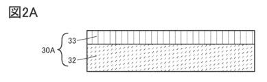
- FIG. 2A a schematic cross-sectional view of a negative electrode 30A is shown in FIG. 2A.
- the negative electrode 30A has a negative electrode active material layer 32 and a coating layer 33.
- the coating layer 33 is provided on the negative electrode active material layer 32.
- the coating layer 33 of the negative electrode 30A is located on the separator 40 side.
- the negative electrode active material layer 32 has a film-like (also called a sheet-like, layer-like, foil-like, etc.) negative electrode active material 34 or a particulate negative electrode active material 34.
- a film-like negative electrode active material 34 when the negative electrode active material layer 32 is a film-like negative electrode active material 34, the negative electrode active material layer 32 is the same as the negative electrode active material 34, and the negative electrode active material layer 32 can be called the negative electrode active material 34.
- the negative electrode active material layer 32 when the negative electrode active material layer 32 has particulate negative electrode active material 34, the negative electrode active material layer 32 has a plurality of particulate negative electrode active materials 34, and can be called a composite layer, a coated electrode layer, etc.
- the coating layer 33 may be made of a material containing titanium as described above, and it is particularly preferable to use metallic titanium.
- the negative electrode active material 34 may be made of, for example, metallic lithium, a carbon material, or an alloy-based material. Details of metallic lithium, a carbon material, or an alloy-based material that may be used as the negative electrode active material 34 are described in detail in the section [Negative electrode active material] below.
- a film of metallic lithium can be used as the negative electrode active material 34, and for example, metallic titanium can be used as the coating layer 33.
- the metallic lithium can also be called the negative electrode active material layer 32.
- metallic lithium foil can be used as the negative electrode active material 34
- metallic titanium can be formed as the coating layer 33 by deposition on the metallic lithium foil.
- deposition methods such as sputtering, CVD (Chemical Vapor Deposition), vacuum deposition, EB (Electron Beam) deposition, and ALD (Atomic Layer Deposition) (thermal ALD, plasma ALD) can be used.
- metallic titanium foil can be used as metallic titanium
- metallic lithium can be formed by depositing a film on the metallic titanium foil.
- a film-forming method such as vacuum deposition or EB deposition can be used.
- metallic lithium can be used as the negative electrode active material 34, and for example, titanium oxide can be used as the coating layer 33.
- metallic lithium foil can be used as metallic lithium
- a titanium oxide film can be formed on the metallic lithium foil.
- Film formation methods such as sputtering, CVD, vacuum deposition, EB deposition, and ALD can be used to form the titanium oxide film.
- the configuration example of the negative electrode 30A is not limited to the above example, and one or more materials selected from the negative electrode active material materials shown in [Negative electrode active material] described below can be used as the negative electrode active material 34, and one or more materials selected from the materials that can be used for the coating layer 33 described above can be used.
- FIG. 2B a schematic cross-sectional view of a negative electrode 30B is shown in FIG. 2B.
- the negative electrode 30B has a negative electrode current collector 31, a negative electrode active material layer 32, and a coating layer 33.
- the negative electrode active material layer 32 is on the negative electrode current collector 31, and the coating layer 33 is on the negative electrode active material layer 32.
- the coating layer 33 of the negative electrode 30B is located on the separator 40 side.
- the negative electrode active material layer 32 has a film-like negative electrode active material 34 or a particulate negative electrode active material 34.
- the materials that can be used as the negative electrode active material 34 and the coating layer 33 can be the materials described for the negative electrode 30A.
- the materials described in the [Negative electrode current collector] below, such as titanium foil, copper foil, and stainless steel foil, can be used as the negative electrode current collector 31.
- the negative electrode 30B for example, copper foil can be used as the negative electrode current collector 31, for example, a film of metallic lithium can be used as the negative electrode active material 34, and for example, metallic titanium can be used as the coating layer 33. Note that the metallic lithium in this case can also be called the negative electrode active material layer 32.
- the negative electrode 30A can be produced by forming a film of metallic lithium on copper foil, and then forming a film of metallic titanium on the metallic lithium.
- the method for forming the metallic lithium film and the metallic titanium film can be the same as the film formation method described for the negative electrode 30A.
- the negative electrode 30B for example, copper foil can be used as the negative electrode current collector 31, for example, a film-like silicon can be used as the negative electrode active material 34, and for example, metallic titanium can be used as the coating layer 33. Note that the silicon in this case can also be called the negative electrode active material layer 32.
- a silicon film can be formed on copper foil, and a titanium metal film can be formed on the silicon.
- the silicon film can be formed by a film formation method such as sputtering, CVD, vacuum deposition, or EB deposition.
- the titanium metal film can be formed by the film formation method described for the negative electrode 30A.
- the configuration example of the negative electrode 30B is not limited to the above example, and the negative electrode current collector 31 may be one selected from the materials described in [Negative electrode current collector] below, the negative electrode active material 34 may be one or more materials selected from the negative electrode active material materials described in [Negative electrode active material] below, and one or more materials selected from the materials that can be used for the coating layer 33 described above, and these may be used in appropriate combination.
- the negative electrode 30C has a base layer 37 on the negative electrode current collector 31, a negative electrode active material layer 32 on the base layer 37, and a coating layer 33 on the negative electrode active material layer 32.
- the coating layer 33 of the negative electrode 30C is located on the separator 40 side.
- the negative electrode active material layer 32 has a film-like negative electrode active material 34 or a particulate negative electrode active material 34.
- the materials that can be used as the negative electrode active material 34 and the coating layer 33 can be the materials described for the negative electrode 30A.
- the materials that can be used as the negative electrode current collector 31 can be the materials described for the negative electrode 30B.
- titanium foil can be used as the negative electrode current collector 31
- metallic titanium can be used as the underlayer 37
- metallic lithium can be used as the negative electrode active material 34 in the form of a film
- metallic titanium can be used as the coating layer 33.
- the metallic lithium in this case can also be called the negative electrode active material layer 32.
- metallic lithium can be formed on titanium foil by deposition
- metallic titanium can be formed on the metallic lithium by deposition.
- the deposition method described for negative electrode 30A can be used to deposit metallic lithium and metallic titanium.
- the configuration example of the negative electrode 30C is not limited to the above example, and the negative electrode current collector 31 may be one selected from the materials described in [Negative electrode current collector] below, the negative electrode active material 34 may be one or more materials selected from the negative electrode active material materials described in [Negative electrode active material] below, and one or more materials selected from the materials that can be used for the coating layer 33 described above may be used.
- FIG. 2D a schematic cross-sectional view of a negative electrode 30D is shown in FIG. 2D.
- the negative electrode 30D has a catalyst layer 38 on the negative electrode current collector 31, a negative electrode active material layer 32 on the catalyst layer 38, and a coating layer 33 on the negative electrode active material layer 32.
- the coating layer 33 of the negative electrode 30D is located on the separator 40 side.
- the negative electrode active material layer 32 of the negative electrode 30D has a film-like negative electrode active material 34, and the negative electrode active material 34 has a carbon material such as CNT or graphite.
- the catalyst layer 38 refers to a layer having a material that promotes the formation of CNTs when the CNTs are formed using a CVD method.
- Iron chloride (FeCl 2 ) can be used as the catalyst layer 38.
- the materials that can be used for the coating layer 33 are the same as those described for the negative electrode 30A.
- the materials that can be used for the negative electrode current collector 31 are the same as those described for the negative electrode 30B.
- a titanium foil can be used as the negative electrode current collector 31
- powdered iron chloride (FeCl 2 ) can be used as the catalyst layer 38
- film-like CNTs can be used as the negative electrode active material 34
- metallic titanium can be used as the coating layer 33.
- the CNTs in this case can also be referred to as the negative electrode active material layer 32.
- powdered iron chloride FeCl 2
- CNTs are formed by a CVD method
- a film of metallic titanium is formed on the CNTs.
- the film formation method described for the negative electrode 30A can be used to form the metallic titanium film.
- the CNT film can be formed, for example, using a CVD device under an environment of 500 Pa to 2000 Pa and 800° C. to 900° C., using acetylene gas.
- the growth direction of the CNTs can be aligned approximately perpendicular to the upper surface of the negative electrode current collector 31. Specifically, approximately perpendicular means that the angle with the surface is between 80° and 100°.
- the configuration example of the negative electrode 30D is not limited to the above example, and the negative electrode current collector 31 can be one selected from the materials described below under [Negative electrode current collector], and one or more materials selected from the materials that can be used for the coating layer 33 described above can be used.
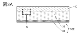
- FIG. 3A a schematic cross-sectional view of a negative electrode 30E and a separator 40 is shown in FIG. 3A.
- the negative electrode 30E has a negative electrode current collector 31 and a negative electrode active material layer 32.
- the negative electrode active material layer 32 of the negative electrode 30E is located on the separator 40 side.
- the coating layer 33 is provided at a position in contact with the separator 40, but the position at which the coating layer 33 is provided is not limited to the above example.
- the coating layer 33 is provided on the surface of the particulate negative electrode active material 34.
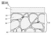
- FIG. 3B and 3C An example of providing a coating layer 33 on the surface of the negative electrode active material 34 of the negative electrode active material layer 32 is shown in Figs. 3B and 3C.
- Figs. 3B and 3C are enlarged views each illustrating an example of the configuration of region C surrounded by a dashed line in Fig. 3A.
- FIG. 3B shows an example of providing a coating layer 33 during the process of producing the negative electrode 30.
- the negative electrode 30E has a negative electrode active material layer 32 on a negative electrode current collector 31, and the negative electrode active material layer 32 has a negative electrode active material 34, a coating layer 33, and a conductive material 36.
- An electrolyte 45 may be present in the voids of the negative electrode active material layer 32.
- the configuration example shown in FIG. 3B can be produced by applying a slurry containing the negative electrode active material 34 (a solution in which the negative electrode active material 34, a conductive material 36, and a dispersion medium are mixed) onto the negative electrode current collector 31, drying it, and then providing a coating layer 33.
- a binder may be included to fix the negative electrode active material layers 32 together and to fix the negative electrode active material 34 to the negative electrode current collector 31.
- the CVD method, sputtering method, or vapor deposition method is used as the method for forming the coating layer 33 in this configuration example, it is difficult to form the coating layer 33 on the negative electrode active material 34 in the portion far from the inner surface of the negative electrode active material layer 32. Therefore, in this configuration example, it is preferable to form the coating layer 33 by the ALD method or a sol-gel method using a liquid such as titanium alkoxide. By forming the coating layer 33 by the ALD method, sol-gel method, or the like, it is possible to provide the coating layer 33 on the entire surface of the particles of the negative electrode active material 34 contained in the negative electrode active material layer 32.
- the coating layer 33 is a conductor such as metallic titanium
- the negative electrode active material layer 32 may not have a material that aids in conductivity (also called a conductive assistant), such as the conductive material 36.
- the coating layer 33 is a semiconductor that has a lower conductivity than a conductor, such as titanium oxide
- the negative electrode active material layer 32 preferably has the conductive material 36.
- the conductive material 36 that the negative electrode active material layer 32 can have one or more materials selected from the materials described below under [Conductive material] can be used.
- the conductivity of the coating layer 33 can be increased by subjecting the coating layer 33 to a reduction treatment.
- the titanium oxide can be reduced using hydrogen, sodium borohydride, or the like as a reducing agent. As a result, the conductivity of the coating layer can be improved.
- FIG. 3C shows an example in which a coating layer 33 is provided in the process of producing the negative electrode active material 34.
- the negative electrode 30E has a negative electrode active material layer 32 on a negative electrode current collector 31, and the negative electrode active material layer 32 has a negative electrode active material 34, a coating layer 33, a binder 35, and a conductive material 36.
- An electrolyte 45 may be present in the voids of the negative electrode active material layer 32.
- the configuration example shown in FIG. 3C can be produced by carrying out a process to provide a coating layer 33 on the negative electrode active material 34, and then coating a slurry containing the negative electrode active material 34 (a solution in which the negative electrode active material 34, a dispersion medium, a binder 35, and a conductive material 36 are mixed) on the negative electrode current collector 31 and drying it.
- a slurry containing the negative electrode active material 34 a solution in which the negative electrode active material 34, a dispersion medium, a binder 35, and a conductive material 36 are mixed
- the coating layer 33 can be formed on the negative electrode active material 34 using the ALD method, the sol-gel method using a liquid such as titanium alkoxide, or the barrel sputtering method (a type of sputtering method in which a film is formed while particulate powder is stirred).
- the coating layer 33 shown in Figures 2A to 3C used in the explanation of negative electrode configuration example 1 to negative electrode configuration example 5 above is illustrated as uniformly covering the surface of the film-like negative electrode active material 34 or the surface of the particulate negative electrode active material 34 without any gaps, but the coating layer 33 may have cracks CR, cavities CA, gaps GA where the coating layer 33 is not provided, etc., as shown in Figure 4A.
- the negative electrode active material 34 and the electrolyte may come into contact.
- the coating layer 33 shown in Figures 2A to 3C used in the explanation of the above negative electrode configuration examples 1 to 5 clearly illustrates the boundary between the surface of the film-like negative electrode active material 34 or the surface of the particulate negative electrode active material 34 and the coating layer 33, but as shown in Figure 4B, an interface layer 39 may be present between the negative electrode active material 34 and the coating layer 33.
- the interface layer 39 may be a region in which at least a portion of the elements contained in the negative electrode active material 34 and the elements contained in the coating layer 33 are mixed.
- the negative electrodes 30 (negative electrodes 30B to 30E) shown in Figs. 2A to 3C used in the description of the negative electrode configuration example 2 to the negative electrode configuration example 5 above are shown as examples having the negative electrode active material layer 32 and the coating layer 33 on one side of the negative electrode current collector 31, but the negative electrode of one embodiment of the present invention is not limited to such a single-sided negative electrode, and may be a double-sided negative electrode (negative electrode 30F) having the negative electrode active material layer 32 and the coating layer 33 on both sides of the negative electrode current collector 31 as shown in Fig. 4C.
- the negative electrode 30F shown in Fig. 4C is an example of a double-sided negative electrode, and shows a case where the negative electrode 30B shown in Fig.
- negative electrode 30F has the negative electrode active material layer 32 on one side and the other side of the negative electrode current collector 31, respectively, and has the coating layer 33 on each of the negative electrode active material layers 32.
- negative electrodes 30C to 30E may also be configured as double-sided negative electrodes.
- the secondary battery 10 may have a separator 40 having the coating layer 33 and a negative electrode not having the coating layer 33.
- the separator 40 may have the coating layer 33 on at least one surface of the separator 40, and the surface having the coating layer 33 may be provided so as to face the negative electrode side not having the coating layer.
- a material that can be used for the coating layer 33 a method for forming the coating layer 33, etc., any of the above-mentioned methods may be used.
- binder it is preferable to use one or more of the following rubber materials: styrene-butadiene rubber, styrene-isoprene-styrene rubber, acrylonitrile-butadiene rubber, butadiene rubber, ethylene-propylene-diene copolymer, butyl rubber, ethylene-propylene rubber, fluororubber, silicone rubber, and urethane rubber.
- the above-mentioned rubber materials can be dispersed in a dispersion medium and used.
- the dispersion medium for example, one or more of the following can be used: water, N-methylpyrrolidone (NMP), methanol, ethanol, acetone, tetrahydrofuran (THF), dimethylformamide (DMF), and dimethylsulfoxide (DMSO).
- NMP N-methylpyrrolidone
- methanol ethanol
- acetone tetrahydrofuran
- DMF dimethylformamide
- DMSO dimethylsulfoxide
- a water-soluble polymer can be used as the binder.
- a polysaccharide can be used as the water-soluble polymer.
- a cellulose derivative such as carboxymethyl cellulose (CMC), methyl cellulose, ethyl cellulose, hydroxypropyl cellulose, diacetyl cellulose, or regenerated cellulose, or starch can be used as the polysaccharide.
- materials such as polystyrene, polymethyl acrylate, polymethyl methacrylate (polymethyl methacrylate, PMMA), sodium polyacrylate, polyvinyl alcohol (PVA), polyethylene oxide (PEO), polypropylene oxide, polyimide, polyvinyl chloride, polytetrafluoroethylene, polyethylene, polypropylene, polyisobutylene, polyethylene terephthalate, nylon, polyvinylidene fluoride (PVDF), polyacrylonitrile (PAN), ethylene propylene diene polymer, polyvinyl acetate, and nitrocellulose may be used as the binder.
- PVA polyethylene oxide
- PEO polypropylene oxide
- polyimide polyvinyl chloride
- PVDF polytetrafluoroethylene
- PAN polyacrylonitrile
- ethylene propylene diene polymer polyvinyl acetate
- nitrocellulose ethylene propylene diene polymer
- a material with particularly excellent viscosity adjustment effects may be used in combination with other materials.
- rubber materials have excellent adhesive strength and elasticity, it may be difficult to adjust the viscosity when mixed with a solvent. In such cases, it is preferable to mix with a material with particularly excellent viscosity adjustment effects.
- a water-soluble polymer may be used as a material with particularly excellent viscosity adjustment effects.
- the above-mentioned polysaccharides for example, carboxymethylcellulose (CMC), methylcellulose, ethylcellulose, hydroxypropylcellulose, and diacetylcellulose, cellulose derivatives such as regenerated cellulose, or starch may be used.
- CMC carboxymethylcellulose
- methylcellulose methylcellulose
- ethylcellulose methylcellulose
- hydroxypropylcellulose hydroxypropylcellulose
- diacetylcellulose cellulose derivatives such as regenerated cellulose, or starch
- the solubility of cellulose derivatives such as carboxymethylcellulose can be increased by converting them into salts such as sodium or ammonium salts of carboxymethylcellulose, making them more effective as viscosity adjusters. Increasing the solubility can also increase the dispersibility with the active material or other components when preparing an electrode slurry.
- the cellulose and cellulose derivatives used as electrode binders include their salts.
- Water-soluble polymers stabilize the viscosity by dissolving in water, and can stably disperse active materials and other materials combined as binders, such as styrene-butadiene rubber, in an aqueous solution.
- binders such as styrene-butadiene rubber
- cellulose derivatives such as carboxymethyl cellulose
- functional groups such as hydroxyl or carboxyl groups
- the polymers are expected to interact with each other and widely cover the surface of the active material.
- a passive film is a film that has no electronic conductivity or has extremely low electronic conductivity.
- a passive film when a passive film is formed on the surface of an active material, it can suppress decomposition of the electrolyte at the battery reaction potential. Furthermore, it is even more desirable for the passive film to suppress electronic conductivity while still being able to conduct lithium ions.
- Negative electrode active material for example, metallic lithium, a carbon material, an alloy material, or the like can be used.
- metallic lithium When metallic lithium is used as the negative electrode active material, metallic lithium on a foil can be used. Metallic lithium can also be vapor-deposited onto a substrate such as a current collector.
- carbon materials examples include graphite (natural graphite, artificial graphite), easily graphitizable carbon (soft carbon), non-graphitizable carbon (hard carbon), carbon fiber (carbon nanotubes), graphene, carbon black, etc.
- Graphite includes artificial graphite and natural graphite.
- artificial graphite include mesocarbon microbeads (MCMB), coke-based artificial graphite, and pitch-based artificial graphite.
- MCMB mesocarbon microbeads
- pitch-based artificial graphite spherical graphite having a spherical shape
- MCMB may have a spherical shape, which is preferable.
- it is relatively easy to reduce the surface area of MCMB which may be preferable.
- natural graphite include flake graphite and spheroidized natural graphite.
- graphite When lithium ions are inserted into graphite (when it is in the state of a lithium-graphite intercalation compound), graphite exhibits a low potential (0.05 V or more and 0.5 V or less vs. Li/Li + ) similar to that of metallic lithium. This allows lithium ion batteries using graphite to exhibit a high operating voltage. Furthermore, graphite is preferable because it has the advantages of a relatively high capacity per unit volume, a relatively small volume expansion, being inexpensive, and being safer than metallic lithium.
- Non-graphitizable carbon can be obtained, for example, by firing synthetic resins such as phenolic resins, or organic matter derived from plants.
- the non-graphitizable carbon contained in the negative electrode active material of a lithium-ion battery according to one embodiment of the present invention preferably has a (002) plane spacing measured by X-ray diffraction (XRD) of 0.34 nm or more and 0.50 nm or less, and more preferably 0.35 nm or more and 0.42 nm or less.
- XRD X-ray diffraction
- the negative electrode active material may be an element capable of performing a charge/discharge reaction by alloying/dealloying reaction with lithium.
- a material containing at least one of silicon, tin, gallium, aluminum, germanium, lead, antimony, bismuth, silver, zinc, cadmium, indium, etc. may be used.
- Such elements have a larger capacity than carbon, and are preferably used as the negative electrode active material. Compounds containing these elements may also be used.
- Examples include SiO, Mg2Si , Mg2Ge , SnO, SnO2 , Mg2Sn , SnS2 , V2Sn3 , FeSn2, CoSn2 , Ni3Sn2 , Cu6Sn5, Ag3Sn , Ag3Sb, Ni2MnSb, CeSb3, LaSn3, La3Co2Sn7 , CoSb3 , InSb , SbSn , etc.
- elements capable of carrying out charge/discharge reactions by alloying/dealloying reactions with lithium, and compounds containing such elements may be referred to as alloy - based materials.
- SiO refers to, for example, silicon monoxide.
- SiO can be expressed as SiO x .
- x preferably has a value of 1 or close to 1.
- x is preferably 0.2 or more and 1.5 or less, and more preferably 0.3 or more and 1.2 or less.
- a mixture of silicon and silicon dioxide may also be called SiO.
- negative electrode active material it is possible to use one type of negative electrode active material from the above-mentioned negative electrode active materials, but it is also possible to use a combination of multiple types. For example, a combination of a carbon material and silicon, or a combination of a carbon material and SiO2 can be used.
- the current collector used for the negative electrode a material having high conductivity, such as metals such as stainless steel, gold, platinum, copper, titanium, and alloys thereof, can be used. In addition, it is preferable that the material used for the negative electrode current collector does not form an alloy with Li at the potential of the negative electrode.
- the current collector can be appropriately shaped in a foil, plate, sheet, mesh, punched metal, expanded metal, or other shape. It is preferable to use a current collector having a thickness of 5 ⁇ m or more and 30 ⁇ m or less.
- the lithium foil when a layer having Ti on a lithium foil is used as the negative electrode, the lithium foil can also function as the negative electrode current collector, so that the negative electrode current collector does not need to be provided. Alternatively, even when the coating layer 33 has a function as the negative electrode current collector, the negative electrode current collector does not need to be provided.
- the conductive material is also called a conductive agent or conductive assistant, and is made of a carbon material.
- attaching does not only refer to the physical adhesion between the active material and the conductive material, but also includes the case where a covalent bond is formed, the case where the conductive material is bonded by van der Waals forces, the case where the conductive material covers a part of the surface of the active material, the case where the conductive material is embedded in the surface irregularities of the active material, and the case where the two materials are electrically connected even if they are not in contact with each other.
- the active material layers such as the positive electrode active material layer and the negative electrode active material layer, preferably contain a conductive material.
- the conductive material for example, one or more of the following can be used: carbon black such as acetylene black and furnace black; graphite such as artificial graphite and natural graphite; carbon fibers such as carbon nanofibers and carbon nanotubes; and graphene compounds.
- carbon fiber for example, mesophase pitch-based carbon fiber, isotropic pitch-based carbon fiber, etc. can be used.
- carbon nanofiber or carbon nanotube can be used as the carbon fiber. Carbon nanotube can be produced, for example, by vapor phase growth method.
- graphene compounds include graphene, multi-layer graphene, multi-graphene, graphene oxide, multi-layer graphene oxide, multi-graphene oxide, reduced graphene oxide, reduced multi-layer graphene oxide, reduced multi-graphene oxide, graphene quantum dots, etc.
- Graphene compounds have carbon, have a shape such as a plate or sheet, and have a two-dimensional structure formed of six-membered carbon rings. The two-dimensional structure formed of six-membered carbon rings may be called a carbon sheet.
- the graphene compound may have a functional group. It is also preferable that the graphene compound has a curved shape.
- the graphene compound may be rolled up to resemble a carbon nanofiber.
- the active material layer may also contain metal powder or metal fibers such as copper, nickel, aluminum, silver, or gold as a conductive material, or a conductive ceramic material.
- the content of the conductive material relative to the total amount of the active material layer is preferably 1 wt% or more and 10 wt% or less, and more preferably 1 wt% or more and 5 wt% or less.
- graphene compounds Unlike granular conductive materials such as carbon black, which make point contact with the active material, graphene compounds enable surface contact with low contact resistance, so a smaller amount than normal conductive materials can improve the electrical conductivity between the granular active material and the graphene compound. This makes it possible to increase the ratio of active material in the active material layer, thereby increasing the discharge capacity of the battery.
- Particulate carbon-containing compounds such as carbon black and graphite, or fibrous carbon-containing compounds such as carbon nanotubes, tend to enter tiny spaces.
- a tiny space refers to, for example, the area between multiple active materials.
- the density of the electrode can be increased and an excellent conductive path can be formed.
- a battery obtained by the manufacturing method of one embodiment of the present invention has a high capacity density and is stable, making it effective as an in-vehicle battery.
- the positive electrode includes a positive electrode active material layer and a positive electrode current collector.
- the positive electrode active material layer includes a positive electrode active material, and may further include at least one of a conductive material and a binder.
- the conductive material and the binder may be the same as those described in the negative electrode section.
- the positive electrode can be formed by applying a slurry onto a current collector and drying it. It is also possible to press the current collector after drying.
- the positive electrode is formed by forming an active material layer on a current collector.
- Slurry is a material liquid used to form an active material layer on a current collector, and contains an active material, a binder, and a solvent, and preferably also contains a conductive material.
- the slurry is also called an electrode slurry or an active material slurry, and when a positive electrode active material layer is formed, it is also called a positive electrode slurry.
- the positive electrode 20 has a positive electrode current collector 21 and a positive electrode active material layer 22 on the positive electrode current collector 21.
- the positive electrode 20 may have a coating layer like the coating layer 33 described for the negative electrode 30, in which case the positive electrode active material 24 has a coating layer 23.
- Materials that can be used as the coating layer 23 include those described in the negative electrode section.
- Figures 5B and 5C An example of providing a coating layer 23 on the surface of the positive electrode active material 24 is shown in Figures 5B and 5C.
- Figures 5B and 5C are enlarged views each illustrating an example of the configuration of region B surrounded by a dashed line in Figure 1A.
- FIG. 5B shows an example of providing a coating layer 23 during the process of producing a positive electrode 20.
- the positive electrode 20 has a positive electrode active material layer 22 on a positive electrode current collector 21, and the positive electrode active material layer 22 has a positive electrode active material 24 and a coating layer 23.
- An electrolyte 45 may be present in the voids of the positive electrode active material layer 22.
- the configuration example shown in FIG. 5B can be produced by applying a slurry containing the positive electrode active material 24 (a solution in which the positive electrode active material 24 is mixed with a dispersion medium) onto the positive electrode current collector 21, drying it, and then providing a coating layer 23.
- a binder may be included to fix the positive electrode active material layers 22 together and to fix the positive electrode active material 24 to the positive electrode current collector 21.
- the CVD method, sputtering method, or vapor deposition method is used as the method for forming the coating layer 23 in this configuration example, it is difficult to form the coating layer 23 on the positive electrode active material 24 in the portion far from the inner surface of the positive electrode active material layer 22. Therefore, in this configuration example, it is preferable to form the coating layer 23 by the ALD method or a sol-gel method using a liquid such as titanium alkoxide. By forming the coating layer 23 by the ALD method, the sol-gel method, or the like, it is possible to provide the coating layer 23 on the entire surface of the particles of the positive electrode active material 24 contained in the positive electrode active material layer 22.
- the positive electrode active material layer 22 does not need to have a material that aids in conductivity, such as a conductive material, as shown in FIG. 5B.
- the coating layer 23 is a semiconductor that has a lower conductivity than a conductor, such as titanium oxide, it is preferable that the positive electrode active material layer 22 has a conductive material.
- the conductivity of the coating layer 23 can be increased by subjecting the coating layer 23 to a reduction treatment.
- the titanium oxide can be reduced using hydrogen, sodium borohydride, or the like as a reducing agent. As a result, the conductivity of the coating layer can be improved.
- FIG. 5C shows an example in which a coating layer 23 is provided in the process of producing the positive electrode active material 24.
- the positive electrode 20 has a positive electrode active material layer 22 on a positive electrode current collector 21, and the positive electrode active material layer 22 has a positive electrode active material 24, a coating layer 23, a binder 25, and a conductive material 26.
- the positive electrode active material layer 22 may have an electrolyte 45 in the voids.
- the conductive material 26 that the positive electrode active material layer 22 can have can be one or more materials selected from the materials described above under [Conductive material].
- the configuration example shown in FIG. 5C can be produced by carrying out a process to provide a coating layer 23 on the positive electrode active material 24, and then coating a slurry containing the positive electrode active material 24 (a solution in which the positive electrode active material 24, a dispersion medium, a binder 25, and a conductive material 26 are mixed) on the positive electrode current collector 21 and drying it.
- a slurry containing the positive electrode active material 24 a solution in which the positive electrode active material 24, a dispersion medium, a binder 25, and a conductive material 26 are mixed
- the process for providing the coating layer 23 on the positive electrode active material 24 can be the ALD method, the sol-gel method using a liquid such as titanium alkoxide, the barrel sputtering method, or the like.
- the positive electrode active material at least one of a composite oxide having a layered rock-salt structure, a composite oxide having an olivine structure, and a composite oxide having a spinel structure can be used.
- the layered rock-salt structure composite oxide may be any one or more of lithium cobalt oxide, lithium nickel-cobalt-manganese oxide, lithium nickel-cobalt-aluminate, and lithium nickel-manganese-aluminate.
- the composition formula may be LiM1O2 (where M1 is one or more selected from nickel, cobalt, manganese, and aluminum), but the coefficients of the composition formula are not limited to integers.
- lithium cobalt oxide for example, lithium cobalt oxide to which magnesium and fluorine have been added can be used. Alternatively, lithium cobalt oxide to which magnesium, fluorine, aluminum, and nickel have been added can be used. Alternatively, lithium cobalt oxide to which magnesium, fluorine, aluminum, nickel, and titanium have been added can be used.
- the lithium nickel-cobalt-manganese oxide it is preferable to use, for example, lithium nickel-cobalt-manganese oxide to which one or more of aluminum, calcium, barium, strontium, and gallium have been added.
- the composite oxide having an olivine structure may be any one or more of lithium iron phosphate, lithium manganese phosphate, lithium cobalt phosphate, and lithium iron manganese phosphate.
- the composition formula can be LiM2PO4 (where M2 is one or more selected from iron, manganese, and cobalt), but the coefficients of the composition formula are not limited to integers.
- it can be used as a composite oxide having a spinel structure such as LiMn 2 O 4 .
- the positive electrode current collector a material having high electrical conductivity, such as metals such as stainless steel, gold, platinum, aluminum, and titanium, and alloys thereof, can be used. In addition, it is preferable that the material used for the positive electrode current collector does not dissolve at the potential of the positive electrode. In addition, an aluminum alloy to which an element that improves heat resistance, such as silicon, titanium, neodymium, scandium, or molybdenum, is added can be used.
- the current collector can be appropriately shaped in a foil, plate, sheet, mesh, punched metal, or expanded metal form. It is preferable to use a current collector having a thickness of 5 ⁇ m or more and 30 ⁇ m or less.
- a gel electrolyte may be used as the electrolyte 45.
- a polymer gel in which a polymer is swollen with an electrolytic solution may be used as the gel electrolyte.
- a semi-solid electrolyte layer can be provided, and safety against leakage and the like can be improved.
- the secondary battery can be made thinner and lighter.
- Polymers that can be gelled include silicone gel, acrylic gel, acrylonitrile gel, polyethylene oxide gel, polypropylene oxide gel, fluorine-based polymer gel, etc.
- polymer for example, a polymer having a polyalkylene oxide structure such as polyethylene oxide, PVDF, polyacrylonitrile, etc., and copolymers containing these can be used.
- PVDF-HFP which is a copolymer of PVDF and hexafluoropropylene (HFP)
- the polymer formed may also have a porous shape.
- Solid electrolyte As the electrolyte 45, a solid electrolyte having an inorganic material such as a sulfide or oxide, a solid electrolyte having a polymer material such as a PEO, etc. can be used. When a solid electrolyte is used, the installation of a separator and/or a spacer becomes unnecessary. In addition, since the entire battery can be solidified, there is no risk of leakage, and safety is dramatically improved.
- the secondary battery preferably has a separator.
- the separator may be made of, for example, paper, nonwoven fabric, glass fiber, ceramics, or synthetic fibers such as nylon (polyamide), vinylon (polyvinyl alcohol fiber), polyester, acrylic, polyolefin, or polyurethane.
- the separator is preferably processed into an envelope shape and disposed so as to encase either the positive electrode or the negative electrode.
- the separator may have a multi-layer structure.
- an organic material film such as polypropylene or polyethylene may be coated with a ceramic material, a fluorine material, a polyamide material, or a mixture of these.
- ceramic materials that can be used include aluminum oxide particles and silicon oxide particles.
- fluorine materials that can be used include PVDF and polytetrafluoroethylene.
- polyamide materials that can be used include nylon and aramid (meta-aramid, para-aramid).
- Coating with ceramic-based materials improves oxidation resistance, suppressing the deterioration of the separator during high-voltage charging and improving the reliability of the secondary battery. Coating with fluorine-based materials also makes it easier for the separator and electrodes to adhere to each other, improving output characteristics. Coating with polyamide-based materials, especially aramid, improves heat resistance, improving the safety of the secondary battery.
- both sides of a polypropylene film may be coated with a mixture of aluminum oxide and aramid.
- the surface of the polypropylene film that comes into contact with the positive electrode may be coated with a mixture of aluminum oxide and aramid, and the surface that comes into contact with the negative electrode may be coated with a fluorine-based material.
- the safety of the secondary battery can be maintained even if the overall thickness of the separator is thin, so the discharge capacity per volume of the secondary battery can be increased.
- the battery's exterior body can be made of a metal material such as aluminum, stainless steel, or titanium, or a resin material.
- a film-shaped exterior body can also be used.
- As the film a three-layer structure film can be used in which one side of a metal thin film or metal foil with excellent flexibility, such as aluminum, stainless steel, titanium, copper, or nickel, has a film made of a material such as polyethylene, polypropylene, polycarbonate, ionomer, or polyamide, and the other side has an insulating synthetic resin film such as a polyamide resin or polyester resin.
- Such a multilayer structure film can be called a laminate film.
- the laminate film may be called an aluminum (aluminum) laminate film, a stainless steel laminate film, a titanium laminate film, a copper laminate film, a nickel laminate film, or the like, using the material name of the metal layer of the laminate film.
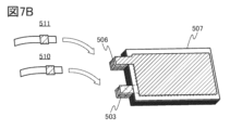
- Fig. 6 and Fig. 7 An example of an external view of a laminated secondary battery 500 is shown in Fig. 6 and Fig. 7.
- Fig. 6 and Fig. 7 have a positive electrode 503, a negative electrode 506, a separator 507, an exterior body 509, a positive electrode lead electrode 510, and a negative electrode lead electrode 511.
- the laminated secondary battery has a flexible structure, and is mounted in an electronic device having at least a part having flexibility, the secondary battery can also be bent in accordance with the deformation of the electronic device.
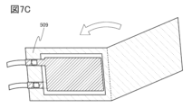
- An example of a method for manufacturing the laminated secondary battery will be described with reference to Figs. 7A to 7C.
- FIG. 7B shows the laminated negative electrode 506, the separator 507, and the positive electrode 503.
- an example is shown in which five sets of negative electrodes and four sets of positive electrodes are used.
- the tab regions of the positive electrodes 503 are joined together, and the positive electrode lead electrode 510 is joined to the tab region of the outermost positive electrode.
- the joining for example, ultrasonic welding or the like may be used.
- the tab regions of the negative electrodes 506 are joined together, and the negative electrode lead electrode 511 is joined to the tab region of the outermost negative electrode.
- FIG. 1A shows a battery configuration in which the negative electrode, the positive electrode, and the separator are each one sheet, but as shown in FIG. 7B, multiple negative electrodes, positive electrodes, and separators can be used.
- the negative electrode 506, separator 507, and positive electrode 503 are placed on the exterior body 509.
- the exterior body 509 is folded at the portion indicated by the dashed line. After that, the outer periphery of the exterior body 509 is joined.
- the joining for example, thermocompression bonding or the like may be used.
- an area (hereinafter referred to as an inlet) that is not joined is provided on a part (or one side) of the exterior body 509 so that the electrolyte can be introduced later.
- an electrolyte (not shown) is introduced into the inside of the exterior body 509 through an inlet provided in the exterior body 509.
- the electrolyte is preferably introduced in a reduced pressure atmosphere or an inert atmosphere.
- the inlet is joined. In this manner, a laminated secondary battery 500 can be produced.
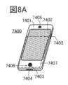
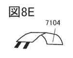
- FIGS 8A to 8G show examples of electronic devices that incorporate the secondary battery described in the previous embodiment.
- Examples of electronic devices that incorporate the secondary battery include television devices (also called televisions or television receivers), computer monitors, digital cameras, digital video cameras, digital photo frames, mobile phones (also called mobile phones or mobile phone devices), portable game machines, personal digital assistants, audio playback devices, and large game machines such as pachinko machines.
- secondary batteries with a flexible shape can be incorporated into the interior or exterior walls of houses and buildings, and along the curved surfaces of the interior or exterior of automobiles.
- FIG. 8A shows an example of a mobile phone.
- the mobile phone 7400 includes a display portion 7402 built into a housing 7401, operation buttons 7403, an external connection port 7404, a speaker 7405, a microphone 7406, and the like.
- the mobile phone 7400 includes a secondary battery 7407.
- a secondary battery of one embodiment of the present invention as the secondary battery 7407, a lightweight mobile phone with a long life can be provided.
- Figure 8B shows the mobile phone 7400 in a bent state.
- the secondary battery 7407 installed inside is also bent.
- Figure 8C shows the state of the bent secondary battery 7407 at that time.
- the secondary battery 7407 is a thin storage battery.
- the secondary battery 7407 is fixed in a bent state.
- the secondary battery 7407 has a lead electrode electrically connected to a current collector.
- FIG. 8D shows an example of a bangle-type display device.
- the portable display device 7100 includes a housing 7101, a display unit 7102, an operation button 7103, and a secondary battery 7104.
- FIG. 8E shows a bent state of the secondary battery 7104.
- the housing deforms, and the curvature of part or all of the secondary battery 7104 changes.
- the degree of bending at any point of the curve expressed by the value of the radius of the corresponding circle is called the radius of curvature, and the reciprocal of the radius of curvature is called the curvature.
- part or all of the main surface of the housing or the secondary battery 7104 changes within a range of 40 mm to 150 mm. If the radius of curvature of the main surface of the secondary battery 7104 is within a range of 40 mm to 150 mm, high reliability can be maintained.
- a secondary battery of one embodiment of the present invention as the secondary battery 7104, a lightweight and long-life portable display device can be provided.
- FIG. 8F shows an example of a wristwatch-type mobile information terminal.
- the mobile information terminal 7200 includes a housing 7201, a display portion 7202, a band 7203, a buckle 7204, operation buttons 7205, an input/output terminal 7206, and the like.
- the portable information terminal 7200 can execute various applications such as mobile phone calls, e-mail, text browsing and creation, music playback, Internet communications, and computer games.
- the display surface of the display unit 7202 is curved, and display can be performed along the curved display surface.
- the display unit 7202 also has a touch sensor, and can be operated by touching the screen with a finger or a stylus. For example, an application can be started by touching an icon 7207 displayed on the display unit 7202.
- the operation button 7205 can have various functions, such as time setting, power on/off operation, wireless communication on/off operation, silent mode activation/cancellation, and power saving mode activation/cancellation.
- the functions of the operation button 7205 can be freely set by an operating system built into the mobile information terminal 7200.
- the mobile information terminal 7200 is also capable of performing standardized short-range wireless communication. For example, it can communicate hands-free by communicating with a wireless headset.
- the portable information terminal 7200 also includes an input/output terminal 7206, and can directly exchange data with other information terminals via a connector. Charging can also be performed via the input/output terminal 7206. Note that charging can also be performed by wireless power supply without using the input/output terminal 7206.
- the display portion 7202 of the mobile information terminal 7200 includes a secondary battery of one embodiment of the present invention.
- a lightweight mobile information terminal with a long life can be provided.
- the secondary battery 7104 shown in FIG. 8E can be incorporated in a curved state inside the housing 7201 or in a bendable state inside the band 7203.
- the mobile information terminal 7200 preferably has a sensor.
- the mobile information terminal 7200 is equipped with a fingerprint sensor, a pulse sensor, a body temperature sensor or other human body sensor, a touch sensor, a pressure sensor, an acceleration sensor, etc.
- FIG. 8G shows an example of an armband-type display device.
- the display device 7300 has a display portion 7304 and a secondary battery of one embodiment of the present invention.
- the display device 7300 can also be provided with a touch sensor in the display portion 7304 and can also function as a portable information terminal.
- the display surface of the display unit 7304 is curved, and display can be performed along the curved display surface.
- the display device 7300 can change the display status by using standardized short-range wireless communication, etc.
- the display device 7300 also has an input/output terminal, and can directly exchange data with other information terminals via a connector. Charging can also be performed via the input/output terminal. Note that charging can also be performed by wireless power supply without using the input/output terminal.
- a lightweight display device with a long life can be provided.
- a secondary battery according to one embodiment of the present invention as a secondary battery in everyday electronic devices, it is possible to provide products that are lightweight and have a long life.
- examples of everyday electronic devices include electric toothbrushes, electric shavers, and electric beauty devices.
- the secondary batteries used in these products it is desirable to have a stick-shaped secondary battery that is easy for users to hold, is small, lightweight, and has a large discharge capacity.
- FIG. 8H is a perspective view of a device also called a tobacco-receiving smoking device (electronic cigarette).
- the electronic cigarette 7500 is composed of an atomizer 7501 including a heating element, a secondary battery 7504 that supplies power to the atomizer, and a cartridge 7502 including a liquid supply bottle and a sensor.
- a protection circuit that prevents overcharging and/or over-discharging of the secondary battery 7504 may be electrically connected to the secondary battery 7504.
- the secondary battery 7504 shown in FIG. 8H has an external terminal so that it can be connected to a charging device. Since the secondary battery 7504 is the tip part when held, it is desirable that the total length is short and the weight is light.
- the secondary battery of one embodiment of the present invention has a high discharge capacity and good cycle characteristics, so that a small and lightweight electronic cigarette 7500 that can be used for a long period of time can be provided.
- Figure 9A shows an example of a wearable device.
- Wearable devices use secondary batteries as a power source. Furthermore, when used by a user at home or outdoors, there is a demand for wearable devices that can be charged wirelessly as well as via wired charging, with an exposed connector, in order to improve splash-proof, water-resistant, or dust-proof performance.
- a secondary battery according to one embodiment of the present invention can be mounted on a glasses-type device 4000 as shown in FIG. 9A.
- the glasses-type device 4000 has a frame 4000a and a display unit 4000b.
- the glasses-type device 4000 can be made lightweight, well-balanced in weight, and capable of long continuous use.
- a configuration can be realized that can accommodate space-saving features that accompany a smaller housing.
- the headset type device 4001 can be equipped with a secondary battery which is one embodiment of the present invention.
- the headset type device 4001 has at least a microphone unit 4001a, a flexible pipe 4001b, and an earphone unit 4001c.
- a secondary battery can be provided in the flexible pipe 4001b and/or the earphone unit 4001c.
- the secondary battery according to one embodiment of the present invention can be mounted on the device 4002 that can be directly attached to the body.
- the secondary battery 4002b can be provided inside the thin housing 4002a of the device 4002.
- the secondary battery according to one embodiment of the present invention can be mounted on the device 4003 that can be attached to clothing.
- the secondary battery 4003b can be provided inside the thin housing 4003a of the device 4003.
- the belt-type device 4006 can be equipped with a secondary battery according to one embodiment of the present invention.
- the belt-type device 4006 has a belt portion 4006a and a wireless power receiving portion 4006b, and a secondary battery can be mounted inside the belt portion 4006a.
- a configuration that can accommodate space saving associated with a miniaturized housing can be realized.
- the secondary battery of one embodiment of the present invention can be mounted on the wristwatch device 4005.
- the wristwatch device 4005 has a display portion 4005a and a belt portion 4005b, and a secondary battery can be provided on the display portion 4005a or the belt portion 4005b.
- the display unit 4005a can display not only the time, but also various other information such as incoming emails and phone calls.
- the wristwatch type device 4005 is a wearable device that is worn directly on the arm, it may be equipped with sensors that measure the user's pulse, blood pressure, etc. It can accumulate data on the user's amount of exercise and health, and manage the user's health.
- Figure 9B shows an oblique view of the wristwatch device 4005 removed from the wrist.
- FIG. 9C shows a state in which a secondary battery 913 is built inside.
- the secondary battery 913 is the secondary battery described in embodiment 2.
- the secondary battery 913 is provided in a position overlapping with the display portion 4005a, and is small and lightweight.
- FIG. 9D shows an example of a wireless earphone.
- the wireless earphone is shown having a pair of main bodies 4100a and 4100b, but this does not necessarily have to be a pair.
- the main bodies 4100a and 4100b each have a driver unit 4101, an antenna 4102, and a secondary battery 4103. They may also have a display unit 4104. They also preferably have a substrate on which a circuit such as a wireless IC is mounted, a charging terminal, and the like. They may also have a microphone.
- the case 4110 has a secondary battery 4111. It also preferably has a board on which circuits such as a wireless IC and a charging control IC are mounted, and a charging terminal. It may also have a display unit, buttons, etc.
- Main units 4100a and 4100b can wirelessly communicate with other electronic devices such as smartphones. This allows sound data and the like sent from other electronic devices to be played on main units 4100a and 4100b. Furthermore, if main units 4100a and 4100b have a microphone, sound picked up by the microphone can be sent to the other electronic device, and the sound data after processing by the electronic device can be sent back to main units 4100a and 4100b for playback. This allows them to be used as, for example, a translation machine.
- the secondary battery 4103 in the main body 4100a can be charged from the secondary battery 4111 in the case 4110.
- the coin-type secondary battery, cylindrical secondary battery, or the like described in the previous embodiment can be used as the secondary battery 4111 and the secondary battery 4103.
- FIG. 10A shows an example of a cleaning robot.
- the cleaning robot 6300 has a display unit 6302 arranged on the top surface of a housing 6301, multiple cameras 6303 arranged on the side, brushes 6304, operation buttons 6305, a secondary battery 6306, various sensors, and the like.
- the cleaning robot 6300 is equipped with tires, a suction port, and the like.
- the cleaning robot 6300 can move by itself, detect dirt 6310, and suck up the dirt from a suction port arranged on the bottom surface.
- the cleaning robot 6300 can analyze an image captured by the camera 6303 and determine whether or not there is an obstacle such as a wall, furniture, or a step. Furthermore, when an object that may become entangled in the brush 6304, such as a wire, is detected by image analysis, the rotation of the brush 6304 can be stopped.
- the cleaning robot 6300 includes therein a secondary battery 6306 according to one embodiment of the present invention and a semiconductor device or electronic component. By using the secondary battery 6306 according to one embodiment of the present invention in the cleaning robot 6300, the cleaning robot 6300 can be an electronic device with long operating time and high reliability.
- FIG. 10B shows an example of a robot.
- the robot 6400 shown in FIG. 10B includes a secondary battery 6409, an illuminance sensor 6401, a microphone 6402, an upper camera 6403, a speaker 6404, a display unit 6405, a lower camera 6406, an obstacle sensor 6407, a movement mechanism 6408, a computing device, etc.
- the microphone 6402 has a function of detecting the user's voice and environmental sounds.
- the speaker 6404 has a function of emitting sound.
- the robot 6400 can communicate with the user using the microphone 6402 and the speaker 6404.
- the display unit 6405 has a function of displaying various information.
- the robot 6400 can display information desired by the user on the display unit 6405.
- the display unit 6405 may be equipped with a touch panel.
- the display unit 6405 may also be a removable information terminal, and by installing it in a fixed position on the robot 6400, charging and data transfer are possible.
- the upper camera 6403 and the lower camera 6406 have the function of capturing images of the surroundings of the robot 6400. Furthermore, the obstacle sensor 6407 can detect the presence or absence of obstacles in the direction of travel when the robot 6400 moves forward using the moving mechanism 6408. The robot 6400 can recognize the surrounding environment and move safely using the upper camera 6403, the lower camera 6406, and the obstacle sensor 6407.
- the robot 6400 includes a secondary battery 6409 according to one embodiment of the present invention and a semiconductor device or electronic component.
- a secondary battery according to one embodiment of the present invention in the robot 6400, the robot 6400 can be an electronic device with long operating time and high reliability.
- FIG. 10C shows an example of an aircraft.
- the aircraft 6500 shown in FIG. 10C has a propeller 6501, a camera 6502, a secondary battery 6503, etc., and has the ability to fly autonomously.
- the flying object 6500 includes therein a secondary battery 6503 according to one embodiment of the present invention.
- the flying object 6500 can be an electronic device with a long operating time and high reliability.
- next-generation clean energy vehicles such as hybrid vehicles (HVs), electric vehicles (EVs), and plug-in hybrid vehicles (PHVs) can be realized.
- HVs hybrid vehicles
- EVs electric vehicles
- PVs plug-in hybrid vehicles
- FIG. 11 illustrates an example of a vehicle using a secondary battery according to one embodiment of the present invention.
- the automobile 8400 illustrated in FIG. 11A is an electric automobile that uses an electric motor as a power source for running. Alternatively, it is a hybrid automobile that can use an electric motor and an engine as a power source for running. By using one embodiment of the present invention, a vehicle with a long driving range can be realized.
- the automobile 8400 also has a secondary battery.
- secondary battery modules can be arranged on the floor of the vehicle interior. The secondary battery can not only drive the electric motor 8406, but also supply power to light-emitting devices such as the headlight 8401 and room light (not shown).
- the secondary battery can also supply power to display devices such as a speedometer and a tachometer that the automobile 8400 has.
- the secondary battery can also supply power to semiconductor devices such as a navigation system that the automobile 8400 has.
- the automobile 8500 shown in FIG. 11B can charge the secondary battery of the automobile 8500 by receiving power supply from an external charging facility by a plug-in method and/or a contactless power supply method.
- FIG. 11B shows a state in which a secondary battery 8024 mounted on the automobile 8500 is being charged from a ground-mounted charging device 8021 via a cable 8022.
- the charging method and connector standards may be appropriately performed using a predetermined method such as CHAdeMO (registered trademark) or combo.
- the charging device 8021 may be a charging station installed in a commercial facility or a home power source.
- the secondary battery 8024 mounted on the automobile 8500 can be charged by an external power supply using plug-in technology. Charging can be performed by converting AC power to DC power via a conversion device such as an AC-DC converter.
- a power receiving device can be mounted on the vehicle and power can be supplied contactlessly from a power transmitting device on the ground for charging.
- this contactless power supply method by incorporating a power transmitting device into the road and/or exterior wall, charging can be performed not only while the vehicle is stopped but also while it is moving.
- This contactless power supply method can also be used to send and receive power between vehicles.
- solar cells can be provided on the exterior of the vehicle to charge the secondary battery when the vehicle is stopped and/or moving. Electromagnetic induction and/or magnetic resonance methods can be used for such contactless power supply.
- FIG. 11C is an example of a two-wheeled vehicle using a secondary battery of one embodiment of the present invention.
- a scooter 8600 shown in FIG. 11C includes a secondary battery 8602, a side mirror 8601, and a turn signal light 8603.
- the secondary battery 8602 can supply electricity to the turn signal light 8603.
- the scooter 8600 shown in FIG. 11C can store a secondary battery 8602 in the under-seat storage 8604.
- the secondary battery 8602 can be stored in the under-seat storage 8604 even if the under-seat storage 8604 is small.
- the secondary battery 8602 is removable, and when charging, the secondary battery 8602 can be carried indoors, charged, and stored before riding.
- the cycle characteristics of the secondary battery are improved, and the discharge capacity of the secondary battery can be increased. Therefore, the secondary battery itself can be made smaller and lighter. If the secondary battery itself can be made smaller and lighter, it will contribute to reducing the weight of the vehicle, and the cruising distance can be improved.
- the secondary battery installed in the vehicle can be used as a power supply source for something other than the vehicle. In this case, for example, it is possible to avoid using a commercial power source during peak power demand. If it is possible to avoid using a commercial power source during peak power demand, it can contribute to energy conservation and reduction of carbon dioxide emissions. Furthermore, if the cycle characteristics are good, the secondary battery can be used for a long period of time, and the amount of rare metals used, including cobalt, can be reduced.
- 10 secondary battery
- 20 positive electrode
- 21 positive electrode current collector
- 22 positive electrode active material layer
- 23 coating layer
- 24 positive electrode active material
- 25 binder
- 26 conductive material
- 30 negative electrode
- 31 negative electrode current collector
- 32 negative electrode active material layer
- 33 coating layer
- 34 negative electrode active material
- 36 conductive material
- 38 catalyst layer
- 50 exterior body
Landscapes
- Chemical & Material Sciences (AREA)
- Engineering & Computer Science (AREA)
- Chemical Kinetics & Catalysis (AREA)
- Electrochemistry (AREA)
- General Chemical & Material Sciences (AREA)
- Manufacturing & Machinery (AREA)
- Materials Engineering (AREA)
- Physics & Mathematics (AREA)
- General Physics & Mathematics (AREA)
- Inorganic Chemistry (AREA)
- Condensed Matter Physics & Semiconductors (AREA)
- Secondary Cells (AREA)
- Battery Electrode And Active Subsutance (AREA)
Abstract
新規な二次電池を提供すること。充電時に負極においてリチウムがデンドライト状に析出することを抑制できる二次電池を提供すること。 負極、電解質及びセパレータを有する二次電池において、負極は、負極活物質と、負極活物質の少なくとも一部を覆う被覆層と、を有し、被覆層は、セパレータと接する領域を有し、被覆層は、チタンを有する材料を有し、電解質は、フッ化環状カーボネートと、フッ化鎖状カーボネートと、を有する、二次電池である。チタンを有する材料として例えば、金属チタンを用いることができる。
Description
本発明の一態様は、二次電池及びその作製方法に関する。
本発明の一態様は、物、方法、又は、製造方法に関する。または、本発明は、プロセス、マシン、マニュファクチャ、又は、組成物(コンポジション・オブ・マター)に関する。本発明の一態様は、半導体装置、表示装置、発光装置、蓄電装置、照明装置、電子機器、車両またはそれらの製造方法に関する。
なお、本明細書中において電子機器とは、蓄電装置を有する装置全般を指し、蓄電装置を有する電気光学装置、蓄電装置を有する情報端末装置などは全て電子機器である。
なお、本明細書中において、蓄電装置とは、蓄電機能を有する素子及び装置全般を指すものであり、例えば、リチウムイオン二次電池などの蓄電装置(二次電池ともいう)、リチウムイオンキャパシタ、及び電気二重層キャパシタなどを含む。
近年、リチウムイオン二次電池、リチウムイオンキャパシタ、空気電池等、種々の蓄電装置の開発が盛んに行われている。特に高出力、高エネルギー密度であるリチウムイオン二次電池は、携帯電話、スマートフォン、もしくはノート型コンピュータ等の携帯情報端末、携帯音楽プレーヤ、デジタルカメラ、医療機器、又は、ハイブリッド車(HV)、電気自動車(EV)、もしくはプラグインハイブリッド車(PHV)等の次世代クリーンエネルギー自動車など、半導体産業の発展と併せて急速にその需要が拡大し、繰り返し充電可能なエネルギーの供給源として現代の情報化社会に不可欠なものとなっている。
リチウムイオン二次電池は、正極、負極及び電解質を少なくとも有する。リチウムイオン二次電池の充電においては、正極からリチウムイオンが脱離し、負極にリチウムイオンが挿入される。また、リチウムイオン二次電池の放電においては、負極からリチウムイオンが脱離し、正極にリチウムイオンが挿入される。正極および負極は、それぞれ活物質(正極活物質、負極活物質)を有している。活物質とは、キャリアであるイオン(リチウムイオン)の挿入・脱離に関わる物質である。
負極活物質としては、酸化還元電位が低いこと、単位体積・単位重量あたりの比容量が高いことから、金属リチウム、黒鉛、シリコン等が好ましい特性を有している。しかし、負極活物質として金属リチウムを用いる場合は、充電時に金属リチウム上にリチウムがデンドライト状(ウィスカー状)に析出する場合があり、このデンドライト状の析出は、セパレータを貫通し、正極と短絡し、リチウムイオン二次電池が発火する原因となる場合がある。なお、デンドライト状に析出したリチウムも、金属リチウムである。また、黒鉛、シリコン等を負極活物質として場合においても、低温での充電、過大な充電電流での充電などをおこなったときに、負極活物質上にリチウムがデンドライト状に析出することがある。デンドライト状に析出したリチウムの引き起こす問題は、二次電池内部での短絡だけでなく、放電時にデンドライト状に析出したリチウムの根本(負極集電体に近い領域)において、当該リチウムが分離し負極から離れることも挙げられる(デッドリチウム化とも呼ぶ)。この場合、二次電池の正極と負極でやりとり可能なリチウムを損なうため、放電容量が低下する。
そのため、リチウムがデンドライト状に析出することを抑制するための研究が行われている(特許文献1)。
二次電池の研究としては、カーボンナノチューブ(CNT:Carbon nanotube)を二次電池に利用する研究なども行われている(特許文献2)。
本発明の一態様は、充電時に負極においてリチウムがデンドライト状に析出することを抑制すること課題の一つとする。また、良好なサイクル特性を有するリチウムイオン二次電池を提供することを課題の一つとする。また、単位質量または単位体積あたりの容量の大きな二次電池を提供することを課題の一つとする。または、本発明の一態様は、新規な負極、新規な二次電池、新規な蓄電装置、新規な負極の製造方法、新規な二次電池の製造方法、または、新規な蓄電装置の製造方法を提供することを課題の一つとする。
本発明の一態様は、負極におけるリチウムイオンの挿入と脱離を良好に行うことを課題の一つとする。また、負極における電解質の分解を抑制することを課題の一つとする。また、氷点下を含む広い温度範囲で充放電可能なリチウムイオン電池を提供することを課題の一つとする。
なお、これらの課題の記載は、他の課題の存在を妨げるものではない。なお、本発明の一態様は、必ずしも、これらの課題の全てを解決する必要はない。なお、これら以外の課題は、明細書、図面、請求項などの記載から、自ずと明らかとなるものであり、明細書、図面、請求項などの記載から、これら以外の課題を抽出することが可能である。
本発明の一態様は、負極、電解質及びセパレータを有する二次電池において、負極は、負極活物質と、負極活物質の少なくとも一部を覆う被覆層と、を有し、被覆層は、セパレータと接する領域と、電解質と接する領域と、を有し、電解質は、フッ化環状カーボネートと、フッ化鎖状カーボネートと、を有する、二次電池である。
または、本発明の一態様は、負極、電解質及びセパレータを有する二次電池において、負極は、負極活物質と、負極活物質の少なくとも一部を覆う被覆層と、を有し、被覆層は、セパレータと接する領域と、電解質と接する領域と、を有し、被覆層は、チタンを有する材料を有し、電解質は、フッ化環状カーボネートと、フッ化鎖状カーボネートと、を有する、二次電池である。
または、本発明の一態様は、負極、電解質及びセパレータを有する二次電池において、負極は、負極活物質と、負極活物質の少なくとも一部を覆う被覆層と、を有し、被覆層は、セパレータと接する領域と、電解質と接する領域と、を有し、被覆層は、金属チタンを有し、電解質は、フッ化環状カーボネートと、フッ化鎖状カーボネートと、を有する、二次電池である。
または、本発明の一態様は、負極、電解質及びセパレータを有する二次電池において、負極は、負極活物質と、負極活物質の少なくとも一部を覆う被覆層と、を有し、被覆層は、セパレータと接する領域と、電解質と接する領域と、を有し、被覆層は、酸化チタンを有し、電解質は、フッ化環状カーボネートと、フッ化鎖状カーボネートと、を有する、二次電池である。
また、上記のいずれか一の二次電池において、負極活物質は、金属リチウムを有することが好ましい。
または、上記のいずれか一の二次電池において、負極活物質は、シリコンを有することが好ましい。
または、上記のいずれか一の二次電池において、フッ化環状カーボネートは、フルオロエチレンカーボネートを有し、フッ化鎖状カーボネートは、トリフルオロプロピオン酸メチルを有することが好ましい。
または、上記のいずれか一の二次電池において、フッ化環状カーボネートは、フルオロエチレンカーボネートを有し、フッ化鎖状カーボネートは、トリフルオロプロピオン酸メチルを有することが好ましい。
または、本発明の一態様は、負極及び電解質を有する二次電池において、負極は、負極集電体と、負極集電体上の負極活物質層と、負極活物質層上の被覆層と、を有し、負極活物質層は、金属リチウムを有し、被覆層は、金属チタンを有し、電解質は、フルオロエチレンカーボネートと、トリフルオロプロピオン酸メチルと、を有する、二次電池である。
本発明の一態様は、負極及び電解質を有する二次電池において、負極は、負極集電体と、負極集電体上の負極活物質層と、負極活物質層上の被覆層と、を有し、負極活物質層は、シリコンを有し、被覆層は、金属チタンを有し、電解質は、フルオロエチレンカーボネートと、トリフルオロプロピオン酸メチルと、を有する、二次電池である。
また、上記のいずれか一の二次電池において、被覆層の厚さは、1nm以上50nm以下である、二次電池である。
本発明の一態様により、充電時に負極においてリチウムがデンドライト状に析出することを抑制することができる。また、良好なサイクル特性を有するリチウムイオン二次電池を提供することができる。また、単位質量及び体積あたりの容量の大きな二次電池を提供することができる。または、本発明の一態様は、新規な負極、新規な二次電池、新規な蓄電装置、新規な負極の製造方法、新規な二次電池の製造方法、または、新規な蓄電装置の製造方法を提供することができる。
本発明の一態様により、負極におけるリチウムイオンの挿入と脱離を良好に行うことができる。また、負極における電解質の分解を抑制することができる。また、氷点下を含む広い温度範囲で充放電可能なリチウムイオン電池を提供することができる。
なお、これらの効果の記載は、他の効果の存在を妨げるものではない。なお、本発明の一態様は、必ずしも、これらの効果の全てを有する必要はない。なお、これら以外の効果は、明細書、図面、請求項などの記載から、自ずと明らかとなるものであり、明細書、図面、請求項などの記載から、これら以外の効果を抽出することが可能である。
図1A及び図1Bは、二次電池の断面模式図である。
図2A乃至図2Dは、負極の断面模式図である。
図3A乃至図3Cは、負極及びセパレータの断面模式図である。
図4A乃至図4Cは、負極の断面模式図である。
図5A乃至図5Cは、正極の断面模式図である。
図6は二次電池の外観を示す図である。
図7A乃至図7Cは二次電池の作製方法を説明する図である。
図8A乃至図8Hは電子機器の一例を説明する図である。
図9A乃至図9Dは電子機器の一例を説明する図である。
図10A乃至図10Cは電子機器の一例を説明する図である。
図11A乃至図11Cは車両の一例を説明する図である。
図2A乃至図2Dは、負極の断面模式図である。
図3A乃至図3Cは、負極及びセパレータの断面模式図である。
図4A乃至図4Cは、負極の断面模式図である。
図5A乃至図5Cは、正極の断面模式図である。
図6は二次電池の外観を示す図である。
図7A乃至図7Cは二次電池の作製方法を説明する図である。
図8A乃至図8Hは電子機器の一例を説明する図である。
図9A乃至図9Dは電子機器の一例を説明する図である。
図10A乃至図10Cは電子機器の一例を説明する図である。
図11A乃至図11Cは車両の一例を説明する図である。
以下では、本発明の実施の形態について図面を用いて詳細に説明する。ただし、本発明は以下の説明に限定されず、その形態および詳細を様々に変更し得ることは、当業者であれば容易に理解される。また、本発明は以下に示す実施の形態の記載内容に限定して解釈されるものではない。
なお、本明細書で説明する各図において、正極、負極、活物質層、セパレータ、外装体などの各構成要素の大きさ及び厚さ等は、個々に説明の明瞭化のために誇張されている場合がある。よって、必ずしも各構成要素はその大きさに限定されず、また各構成要素間での相対的な大きさに限定されない。
また、本明細書等において、第1、第2、第3などとして付される序数詞は、便宜上用いるものであって工程の順番、上下の位置関係などを示すものではない。そのため、例えば、「第1の」を「第2の」又は「第3の」などと適宜置き換えて説明することができる。また、本明細書等に記載されている序数詞と、本発明の一態様を特定するために用いられる序数詞は一致しない場合がある。
また、本明細書等で説明する本発明の一態様の構成において、同一部分又は同様の機能を有する部分には同一の符号を異なる図面間で共通して用い、その繰り返しの説明は省略する。また、同様の機能を有する部分を指す場合には、ハッチパターンを同じくし、特に符号を付さない場合がある。
また、この発明を実施するための形態に記載の内容は、適宜組み合わせて用いることができる。
(実施の形態1)
本実施の形態では、図1A乃至図7Cを用いて、本発明の一態様の二次電池の構成例について説明する。
本実施の形態では、図1A乃至図7Cを用いて、本発明の一態様の二次電池の構成例について説明する。
<二次電池>
図1Aは、本発明の一態様の二次電池10の断面の一部を説明する模式図である。図1Bは、図1Aにおいて破線で囲まれた領域Aの構成例を説明する拡大図である。また、図5B及び図5Cは、図1Aにおいて破線で囲まれた領域Bの構成例を説明する拡大図である。
図1Aは、本発明の一態様の二次電池10の断面の一部を説明する模式図である。図1Bは、図1Aにおいて破線で囲まれた領域Aの構成例を説明する拡大図である。また、図5B及び図5Cは、図1Aにおいて破線で囲まれた領域Bの構成例を説明する拡大図である。
図1Aに示すように、二次電池10は、正極20、負極30、セパレータ40及び外装体50を有する。二次電池10において、正極20、負極30及びセパレータ40は、外装体50に覆われた二次電池10の内部に位置する。また、正極20と、負極30とは、セパレータ40を介して重なる領域を有する。なお、図1Aにおいて図示していないが二次電池10は、外装体50に覆われた二次電池10の内部に電解質を有する。
図1Bを用いて、本発明の一態様の負極30及び電解質45について説明する。図1Bにおいて、負極30は、被覆層33と、負極活物質34と、を有する。また、セパレータ40は、空隙を有し、当該空隙において電解質45を有する。また、電解質はリチウムイオンを有する。図1Bに示すセパレータ40において破線で示すように、セパレータ40が有する空隙は、セパレータ40の内部で3次元的に広がっている。なお、図1B以外の図面において、セパレータ40が有する空隙等を省略して図示する。
<負極>
本発明の一態様の負極30において、負極活物質34は、その表面に被覆層33を有し、被覆層33は、セパレータ40と接する領域と、電解質45と接する領域と、を有する。
本発明の一態様の負極30において、負極活物質34は、その表面に被覆層33を有し、被覆層33は、セパレータ40と接する領域と、電解質45と接する領域と、を有する。
[被覆層]
被覆層33は、電解質45に含まれるリチウムイオンを透過する機能を有し、二次電池10の充電において、図1Bにおける矢印D1のように、セパレータ40の空隙に含まれる電解質45から、リチウムイオンが被覆層33を透過して、負極活物質34に移動する。また、二次電池10の放電において、図1Bにおける矢印D2のように、負極活物質34から、被覆層33を透過して、セパレータ40の空隙に含まれる電解質45へと、リチウムイオンが移動する。
被覆層33は、電解質45に含まれるリチウムイオンを透過する機能を有し、二次電池10の充電において、図1Bにおける矢印D1のように、セパレータ40の空隙に含まれる電解質45から、リチウムイオンが被覆層33を透過して、負極活物質34に移動する。また、二次電池10の放電において、図1Bにおける矢印D2のように、負極活物質34から、被覆層33を透過して、セパレータ40の空隙に含まれる電解質45へと、リチウムイオンが移動する。
[充電]
このように、二次電池10の充電において、負極活物質34は、被覆層33を介してリチウムの挿入を行うことができる。このような構成においては、被覆層33を介して移動することで、当該リチウムの流れを分散させることができると考えられる。その結果、負極活物質34の表面において、局所的にリチウムが析出することを抑制することができる。また、負極において局所的にリチウムが析出することは、リチウムがデンドライト状に析出する原因と考えられている。つまり、本発明の一態様の二次電池10は、負極活物質34の表面に被覆層33を有することで、リチウムがデンドライト状に析出することを抑制することが可能となる。
このように、二次電池10の充電において、負極活物質34は、被覆層33を介してリチウムの挿入を行うことができる。このような構成においては、被覆層33を介して移動することで、当該リチウムの流れを分散させることができると考えられる。その結果、負極活物質34の表面において、局所的にリチウムが析出することを抑制することができる。また、負極において局所的にリチウムが析出することは、リチウムがデンドライト状に析出する原因と考えられている。つまり、本発明の一態様の二次電池10は、負極活物質34の表面に被覆層33を有することで、リチウムがデンドライト状に析出することを抑制することが可能となる。
[放電]
また、二次電池10の放電において、負極活物質34は、被覆層33を介してリチウムの脱離を行うことができる。このような構成においては、被覆層33を介して移動することで、当該リチウムの流れを分散させることができると考えられる。
また、二次電池10の放電において、負極活物質34は、被覆層33を介してリチウムの脱離を行うことができる。このような構成においては、被覆層33を介して移動することで、当該リチウムの流れを分散させることができると考えられる。
ここで、シリコン、錫などの、リチウムと合金を形成する負極活物質は、充放電における体積変化が大きいことが知られている。そのため、放電時に負極活物質からリチウムが脱離する際に、負極活物質の表面側からリチウムが脱離するため、負極活物質は表面側から体積が縮小し、負極活物質がひび割れてしまう可能性がある。
一方、本発明の一態様の二次電池10において、負極活物質34から脱離するリチウムは、電解質45へと直接脱離するのではなく、被覆層33を通って電解質45へと脱離する。そのため、被覆層33を有することによって、負極活物質34からのリチウムの脱離が分散される可能性がある。また、被覆層33が、負極活物質34の形状を維持する機能を有する可能性もある。つまり、本発明の一態様の二次電池10は、負極活物質34の表面に被覆層33を有することで、当該負極活物質34のひび割れを抑制できる可能性がある。
以上に示したように、本発明の一態様の二次電池10において、負極活物質34は被覆層33を有する。被覆層33は、負極活物質34の全ての表面に設けられることが好ましいが、必ずしも負極活物質34の表面の全てに設ける必要はなく、負極活物質34の少なくとも一部を覆うとよい。例えば、被覆層33は、負極活物質34の表面の50%以上に設けられることが好ましく、60%以上に設けられることがより好ましく、70%以上に設けられることがより好ましく、80%以上に設けられることがより好ましく、90%以上に設けられることがより好ましく、95%以上に設けられることがより好ましい。よって、被覆層33は、負極活物質34の表面の全体を覆うように設けてもよいし、負極活物質34の表面に島状に設けてもよい。また、負極活物質34の表面と電解質45が接する領域を有していてもよい。
被覆層33として、導体(導電性材料ともいう)又は半導体性材料を用いることができる。被覆層33として例えば、チタンを有する材料を用いることができる。チタンを有する材料とは、チタン及びチタン化合物のことをいう。チタン化合物として例えば、酸化チタンが挙げられる。なお、金属であるチタンのことを明示的に金属チタンと呼ぶ場合がある。例えば、金属チタンにおいて、リチウムは金属チタンの結晶粒界を通ることができる。
金属チタンの有無は、例えばXPS(X線高電子分光)によって分析することができ、金属チタンを有する場合は454eV付近にエネルギーピークを確認することができる。
または、被覆層33として例えば、ルテニウムを有する材料を用いることができる。ルテニウムを有する材料とは、ルテニウム及びルテニウム化合物のことをいう。ルテニウム化合物として例えば、酸化ルテニウムが挙げられる。
被覆層33の厚さは、1nm以上10μm以下とすることができ、1nm以上1μm以下であることが好ましく、1nm以上100nm以下であることがより好ましく、1nm以上50nm以下であることがより好ましく、1nm以上40nm以下であることがより好ましく、1nm以上30nm以下であることがより好ましく、1nm以上20nm以下であることがより好ましく、1nm以上10nm以下であることがより好ましく、1nm以上5nm以下であることがより好ましく、1nm以上2nm以下であることがより好ましい。被覆層33の厚さを上記の範囲にすることにより、負極活物質34からリチウムを好適に挿入及び脱離させることができる。
<電解質>
本発明の一態様の電池が有する電解質45の一つの形態として、有機溶媒と、有機溶媒に溶解したリチウム塩と、を有する液体電解質(電解液ともいう)を用いることができる。
本発明の一態様の電池が有する電解質45の一つの形態として、有機溶媒と、有機溶媒に溶解したリチウム塩と、を有する液体電解質(電解液ともいう)を用いることができる。
本発明の一態様の電池は、上述した負極30と、電解質45を少なくとも含むことにより、負極活物質34におけるリチウムイオンの挿入と脱離を良好に行うことができる。または、氷点下を含む広い温度範囲で充放電可能な電池を実現することができる。本発明の一態様の電池に用いることができる、有機溶媒とリチウム塩とを有する電解質について、以下で説明する。
[有機溶媒]
本実施の形態で説明する電解質が有する有機溶媒は、フッ化環状カーボネート(フッ素化環状カーボネートと記すこともある)、又はフッ化鎖状カーボネート(フッ素化鎖状カーボネートと記すこともある)を含むとよい。さらに上記有機溶媒は、フッ化環状カーボネート、及びフッ化鎖状カーボネートをともに含むと好ましい。フッ化環状カーボネート及びフッ化鎖状カーボネートは共に、電子求引性を示す置換基を有しており、電子求引性を示す置換基を有さない有機化合物と比べるとリチウムイオンの溶媒和エネルギーが低い。そのためフッ化環状カーボネート及びフッ化鎖状カーボネートは共に有機溶媒に好適である。本明細書等において、カーボネートとは、分子構造に炭酸エステルを少なくとも一つ有する化合物を指し、特に断りがない限り、環状カーボネート及び鎖状カーボネートが含まれる。また、鎖状とは、直鎖状または分岐鎖状の両方が含まれる。
本実施の形態で説明する電解質が有する有機溶媒は、フッ化環状カーボネート(フッ素化環状カーボネートと記すこともある)、又はフッ化鎖状カーボネート(フッ素化鎖状カーボネートと記すこともある)を含むとよい。さらに上記有機溶媒は、フッ化環状カーボネート、及びフッ化鎖状カーボネートをともに含むと好ましい。フッ化環状カーボネート及びフッ化鎖状カーボネートは共に、電子求引性を示す置換基を有しており、電子求引性を示す置換基を有さない有機化合物と比べるとリチウムイオンの溶媒和エネルギーが低い。そのためフッ化環状カーボネート及びフッ化鎖状カーボネートは共に有機溶媒に好適である。本明細書等において、カーボネートとは、分子構造に炭酸エステルを少なくとも一つ有する化合物を指し、特に断りがない限り、環状カーボネート及び鎖状カーボネートが含まれる。また、鎖状とは、直鎖状または分岐鎖状の両方が含まれる。
フッ化環状カーボネートとして、フルオロエチレンカーボネート(フッ化エチレンカーボネート、炭酸フルオロエチレン、FEC、F1ECとも記す)、ジフルオロエチレンカーボネート(DFEC、F2EC)、トリフルオロエチレンカーボネート(F3EC)、またはテトラフルオロエチレンカーボネート(F4EC)等を用いることができる。なお、DFECには、シス−4,5、トランス−4,5等の異性体がある。いずれのフッ化環状カーボネートも電子求引性を示す置換基を有するため、リチウムイオンの溶媒和エネルギーが低いと考えられる。
下記構造式(H10)は、FECの構造式である。FECにおいて電子求引性の置換基はF基である。

フッ化鎖状カーボネートとして、3,3,3−トリフルオロプロピオン酸メチルがある。下記構造式(H22)は3,3,3−トリフルオロプロピオン酸メチルの構造式である。3,3,3−トリフルオロプロピオン酸メチルの略称は、「MTFP」である。MTFPにおいて、電子求引性の置換基はCF3基である。
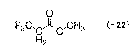
フッ化鎖状カーボネートとして、3,3,3−トリフルオロプロピオン酸トリフルオロメチルがある。下記構造式(H23)は3,3,3−トリフルオロプロピオン酸トリフルオロメチルの構造式である。電子求引性の置換基はCF3基である。

フッ化鎖状カーボネートとして、プロピオン酸トリフルオロメチルがある。下記構造式(H24)はプロピオン酸トリフルオロメチルの構造式である。電子求引性の置換基はCF3基である。
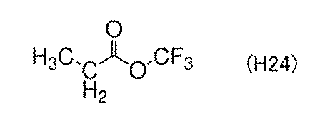
フッ化鎖状カーボネートとして、2,2−ジフルオロプロピオン酸メチルがある。下記構造式(H25)は2,2−ジフルオロプロピオン酸メチルの構造式である。電子求引性の置換基はCF2基である。

本発明の一態様である電解質が有する有機溶媒として、上述したフッ化環状カーボネートから選ばれた一以上及びフッ化鎖状カーボネートから選ばれた一以上を含むとよい。たとえば本実施の形態で説明する有機溶媒は、FECと、MTFPとを含むとよい。その理由を説明する。
[FEC及びMTFP]
FECは、環状カーボネートの一つであり、高い比誘電率を有するため、有機溶媒に用いると、リチウム塩の解離を促進させる効果を有する。一方でFECは電子求引性を示す置換基を有するため、エチレンカーボネート(EC)よりもリチウムイオンとの脱溶媒和が進みやすい。具体的にはFECはリチウムイオンの溶媒和エネルギーが、電子求引性を示す置換基を有さないECよりも小さい。そのため、正極活物質表面および負極活物質表面においてリチウムイオンを離しやすく、二次電池の内部抵抗を低くできる。さらにFECは最高被占有軌道(HOMO:Highest Occupied Molecular Orbital)準位が深いため、酸化されにくく耐酸化性が向上する。一方で、FECは粘度が高いことが懸念される。そこで、FECのみではなく、MTFPを更に含んだ混合有機溶媒を電解液に用いるとよい。MTFPは、鎖状カーボネートの一つであり、電解液の粘度を下げる、又は低温下(代表的には0℃)でも室温下(代表的には25℃)の粘度を維持する効果を有することも可能である。さらにMTFPは、電子求引性を示す置換基を有さないプロピオン酸メチル(略称は「MP」である)よりも溶媒和エネルギーが小さいものの、電解液に用いた際にリチウムイオンとの溶媒和を生成することがあってもよい。
FECは、環状カーボネートの一つであり、高い比誘電率を有するため、有機溶媒に用いると、リチウム塩の解離を促進させる効果を有する。一方でFECは電子求引性を示す置換基を有するため、エチレンカーボネート(EC)よりもリチウムイオンとの脱溶媒和が進みやすい。具体的にはFECはリチウムイオンの溶媒和エネルギーが、電子求引性を示す置換基を有さないECよりも小さい。そのため、正極活物質表面および負極活物質表面においてリチウムイオンを離しやすく、二次電池の内部抵抗を低くできる。さらにFECは最高被占有軌道(HOMO:Highest Occupied Molecular Orbital)準位が深いため、酸化されにくく耐酸化性が向上する。一方で、FECは粘度が高いことが懸念される。そこで、FECのみではなく、MTFPを更に含んだ混合有機溶媒を電解液に用いるとよい。MTFPは、鎖状カーボネートの一つであり、電解液の粘度を下げる、又は低温下(代表的には0℃)でも室温下(代表的には25℃)の粘度を維持する効果を有することも可能である。さらにMTFPは、電子求引性を示す置換基を有さないプロピオン酸メチル(略称は「MP」である)よりも溶媒和エネルギーが小さいものの、電解液に用いた際にリチウムイオンとの溶媒和を生成することがあってもよい。
上述した有機溶媒は、粒状のごみ、または有機溶媒の構成分子以外の分子(以下、単に「不純物」とも呼び、酸素(O2)又は水(H2O)が含まれる。)の含有量が少なく、高純度化されていることが好ましい。また適切な精製を経て、合成時の反応副生成物が抑制されていると好ましい。具体的には、電解質の不純物が100ppm以下、好ましくは50ppm以下、さらに好ましくは10ppm未満とする。不純物のうち水の濃度はカールフィッシャー滴定法によって検出することができる。
さらに上述した有機溶媒は、NMR測定等により不純物に起因するピークがほぼ確認できないことが好ましい。ほぼ確認できないとは、主成分に起因するピークの積分面積に対して不純物に起因するピークの積分面積の比(単に積分比と呼ぶ)が0.005以下、好ましくは0.002以下となることを含む。NMR測定に用いる装置は特に限定されないが、たとえばBruker社の「AVANCE III 400型」を用いることができる。また1H−NMR測定において溶媒に用いるアセトニトリル−d3由来のアセトニトリルの5本のピークのうち、中心のピークを1.94ppmとすることができる。
たとえばMTFPの場合、アセトニトリル−d3溶媒を用いて1H−NMRを測定したとき、δが3.29ppm以上3.43ppm以下に4本のピークが生じることが知られている。しかしこの近傍に他のピークが生じた場合、たとえばδが3.24ppm以上3.29ppm以下にピークが生じた場合、当該ピークは不純物由来と考えられる。そのため3.29ppm以上3.43ppm以下のピーク面積に対する、3.24ppm以上3.29ppm以下のピーク面積の比率(積分比)が0.005以下、好ましくは0.002以下であれば、不純物に起因するピークがほぼ確認できないということができる。
このような物性を有するFEC、及びMTFPを、これら2つの有機溶媒の全含有量を100vol%として、体積比がx:100−x(ただし、5≦x≦30、好ましくは10≦x≦20である。)となるように混合して用いるとよい。有機溶媒において、MTFPがFECよりも多くなるように混合するとよい。なお、上記の体積比は、有機溶媒の混合前に計測した体積比であってもよく、また当該有機溶媒を混合する際の外気は室温(代表的には、25℃)であってもよい。FEC、及びMTFPが混合された有機溶媒はリチウムイオン電池として動作可能な粘性を発現し、氷点下であっても適切な粘性を維持するため好ましい。
上記ではFECを代表として説明したが、フッ化環状カーボネートとして述べたいずれの有機化合物においても、リチウム塩の解離を促進させる効果を有すること、溶媒和エネルギーが小さくリチウムイオンと溶媒和を生成しやすいこと、粘度が高くそれのみで用いると氷点下で使用が難しいといえる。また上記ではMTFPを代表として説明したが、フッ化鎖状カーボネートとして述べたいずれの有機化合物においても、本発明の一態様である電解質の粘度を下げる、又は維持する効果を有するといえる。よって、本発明の一態様である有機溶媒がフッ化環状カーボネートとフッ化鎖状カーボネートとを含むものであれば、負極活物質におけるリチウムイオンの挿入と脱離を良好に行うことができ、且つ、氷点下を含む広い温度範囲で充放電可能なリチウムイオン電池を提供することができる。
本発明の一態様の電池に用いる電解質45が、上記に説明したフッ化環状カーボネート、及びフッ化鎖状カーボネートをともに含む場合、充電反応及び放電反応の反応抵抗を低くすることができる。これは、電解質45を用いることで、負極活物質34の表面または被覆層33の表面における、電解質の分解反応が抑制されているため、と考えることができる。
上述した有機溶媒は、粒状のごみ、または有機溶媒の構成元素以外の元素の含有量が少なく、高純度化されていることが好ましい。具体的には、有機溶媒の重量に対する不純物の重量の比率を1000ppm以下、好ましくは100ppm以下、より好ましくは50ppm以下、更に好ましくは10ppm以下とするとよい。
[リチウム塩]
上記有機溶媒に溶解させるリチウム塩は、例えば、LiPF6、LiClO4、LiAsF6、LiBF4、LiAlCl4、LiSCN、LiBr、LiI、Li2SO4、Li2B10Cl10、Li2B12Cl12、LiCF3SO3、LiC4F9SO3、LiC(CF3SO2)3、LiC(C2F5SO2)3、LiN(CF3SO2)2、LiN(C4F9SO2)(CF3SO2)、LiN(C2F5SO2)2、リチウムビス(オキサレート)ボレート(LiBOB)のうち少なくとも一を用いることができ、上述したリチウム塩を任意の組み合わせ、且つ任意の比率で用いてもよい。
上記有機溶媒に溶解させるリチウム塩は、例えば、LiPF6、LiClO4、LiAsF6、LiBF4、LiAlCl4、LiSCN、LiBr、LiI、Li2SO4、Li2B10Cl10、Li2B12Cl12、LiCF3SO3、LiC4F9SO3、LiC(CF3SO2)3、LiC(C2F5SO2)3、LiN(CF3SO2)2、LiN(C4F9SO2)(CF3SO2)、LiN(C2F5SO2)2、リチウムビス(オキサレート)ボレート(LiBOB)のうち少なくとも一を用いることができ、上述したリチウム塩を任意の組み合わせ、且つ任意の比率で用いてもよい。
以上のとおり、本発明の一態様の電池に用いることが可能な電解質の一例について説明したが、本発明の一態様の電池に用いることが可能な電解質は、この一例に限定解釈されるものではない。
本発明の一態様の電池は、上述した負極30と、電解質45を少なくとも含むことにより、負極活物質34におけるリチウムイオンの挿入と脱離を良好に行うことができ、且つ、氷点下を含む広い温度範囲で充放電可能な電池を実現することができる。
図2A乃至図3Cを用いて、本発明の一態様の、被覆層33を有する負極30の構成例について説明する。
[負極の構成例1]
負極30の構成例として、図2Aに負極30Aの断面模式図を示す。
負極30の構成例として、図2Aに負極30Aの断面模式図を示す。
負極30Aは、負極活物質層32と、被覆層33と、を有する。負極30Aにおいて、負極活物質層32上に被覆層33を有する。二次電池10において、負極30Aが有する被覆層33は、セパレータ40側に位置する。
負極活物質層32は、膜状(シート状、層状、箔状などともいう)の負極活物質34または粒子状の負極活物質34を有する。負極30Aの構成において、負極活物質層32が膜状の負極活物質34である場合、負極活物質層32は負極活物質34と同一であり、負極活物質層32のことを負極活物質34と呼ぶことができる。また、負極30Aの構成において、負極活物質層32が粒子状の負極活物質34を有する場合、負極活物質層32は複数の粒子状の負極活物質34を有し、合材層、塗布電極層などと呼ぶことができる。
被覆層33は、前述のチタンを有する材料などを用いることができ、特に、金属チタンを用いることが好ましい。また、負極活物質34として、例えば金属リチウム、炭素材料、合金系材料などを用いることができる。負極活物質34として用いることのできる、金属リチウム、炭素材料、合金系材料の詳細は、後述の[負極活物質]に示す。
負極30Aの構成例として、負極活物質34として例えば、膜状の金属リチウムを用い、被覆層33として例えば、金属チタンを用いることができる。なお、この場合の金属リチウムは、負極活物質層32と呼ぶこともできる。
ここで例えば、負極活物質34として、金属リチウム箔を用いて、当該金属リチウム箔上に、被覆層33として金属チタンを成膜により形成することができる。金属チタンの成膜には、スパッタリング法、CVD(Chemical Vapor Deposition)法、真空蒸着法、EB(Electron Beam)蒸着法、ALD(Atomic Layer Deposition)法(熱ALD、プラズマALD)などの成膜方法を用いることができる。
金属チタンをスパッタリング法で成膜する場合は、成膜された膜中に柱状結晶が形成される成膜条件を用いることが好ましい。
または例えば、金属チタンとして、金属チタン箔を用いて、当該金属チタン箔上に金属リチウムを成膜により形成することができる。金属リチウムの成膜には、真空蒸着法、EB蒸着法などの成膜方法を用いることができる。
または、負極30Aの別の構成例として、負極活物質34として例えば、金属リチウムを用い、被覆層33として例えば、酸化チタンを用いることができる。
ここで例えば、金属リチウムとして、金属リチウム箔を用いて、当該金属リチウム箔上に酸化チタンを成膜により形成することができる。酸化チタンの成膜には、スパッタリング法、CVD法、真空蒸着法、EB蒸着法、ALD法などの成膜方法を用いることができる。
負極30Aの構成例は、上記の例に限られず、負極活物質34として後述の[負極活物質]に示す負極活物質材料から選択される一以上の材料を用い、上述の被覆層33に用いることができる材料から選択される一以上の材料を用いることができる。
[負極の構成例2]
負極30の構成例として、図2Bに負極30Bの断面模式図を示す。
負極30の構成例として、図2Bに負極30Bの断面模式図を示す。
負極30Bは、負極集電体31と、負極活物質層32と、被覆層33と、を有する。負極30Bにおいて、負極集電体31上に負極活物質層32を有し、負極活物質層32上に被覆層33を有する。二次電池10において、負極30Bが有する被覆層33は、セパレータ40側に位置する。
負極30Aにおける説明と同様に、負極活物質層32は、膜状の負極活物質34または粒子状の負極活物質34を有する。
負極活物質34として用いることのできる材料、及び被覆層33として用いることのできる材料は、負極30Aで説明した材料を用いることができる。また、負極集電体31として、チタン箔、銅箔、ステンレス箔など、後述の[負極集電体]に記載の材料を用いることができる。
負極30Bの構成例として、負極集電体31として例えば、銅箔を用い、負極活物質34として例えば、膜状の金属リチウムを用い、被覆層33として例えば、金属チタンを用いることができる。なお、この場合の金属リチウムは、負極活物質層32と呼ぶこともできる。
ここで例えば、銅箔上に金属リチウムを成膜により形成し、当該金属リチウム上に、金属チタンを成膜により形成することで作製することができる。金属リチウムの成膜方法及び金属チタンの成膜方法は、負極30Aで説明した成膜方法を用いることができる。
または、負極30Bの別の構成例として、負極集電体31として例えば、銅箔を用い、負極活物質34として例えば、膜状のシリコンを用い、被覆層33として例えば、金属チタンを用いることができる。なお、この場合のシリコンは、負極活物質層32と呼ぶこともできる。
ここで例えば、銅箔上にシリコンを成膜により形成し、当該シリコン上に、金属チタンを成膜により形成することができる。シリコンの成膜には、スパッタリング法、CVD法、真空蒸着法、EB蒸着法などの成膜方法を用いることができる。金属チタンの成膜方法は、負極30Aで説明した成膜方法を用いることができる。
負極30Bの構成例は、上記の例に限られず、負極集電体31として後述の[負極集電体]に記載の材料から選択される一を用い、負極活物質34として後述の[負極活物質]に示す負極活物質材料から選択される一以上の材料を用い、上述の被覆層33に用いることができる材料から選択される一以上の材料を用い、これらを適宜組み合わせて用いることができる。
[負極の構成例3]
負極30の構成例として、図2Cに負極30Cの断面模式図を示す。
負極30の構成例として、図2Cに負極30Cの断面模式図を示す。
負極30Cは、負極集電体31上の下地層37と、下地層37上の負極活物質層32と、負極活物質層32上の被覆層33と、を有する。二次電池10において、負極30Cが有する被覆層33は、セパレータ40側に位置する。
負極30Aにおける説明と同様に、負極活物質層32は、膜状の負極活物質34または粒子状の負極活物質34を有する。
負極活物質34として用いることのできる材料、及び被覆層33として用いることのできる材料は、負極30Aで説明した材料を用いることができる。また、負極集電体31として用いることのできる材料は、負極30Bで説明した材料を用いることができる。
負極30Cの構成例として例えば、負極集電体31としてチタン箔を用い、下地層37として金属チタンを用い、負極活物質34として膜状の金属リチウムを用い、被覆層33として金属チタンを用いることができる。なお、この場合の金属リチウムは、負極活物質層32と呼ぶこともできる。
ここで例えば、チタン箔上に金属リチウムを成膜により形成し、当該金属リチウム上に、金属チタンを成膜により形成することができる。金属リチウム及び金属チタンの成膜には、負極30Aで説明した成膜方法を用いることができる。
上記の例のように、膜状の金属リチウムの成膜を行う際に、下地層37として成膜された金属チタンを有する場合、当該金属リチウムの平坦性が良好になることが期待できる。
負極30Cの構成例は、上記の例に限られず、負極集電体31として後述の[負極集電体]に記載の材料から選択される一を用い、負極活物質34として後述の[負極活物質]に示す負極活物質材料から選択される一以上の材料を用い、上述の被覆層33に用いることができる材料から選択される一以上の材料を用いることができる。
[負極の構成例4]
負極30の構成例として、図2Dに負極30Dの断面模式図を示す。
負極30の構成例として、図2Dに負極30Dの断面模式図を示す。
負極30Dは、負極集電体31上の触媒層38と、触媒層38上の負極活物質層32と、負極活物質層32上の被覆層33と、を有する。二次電池10において、負極30Dが有する被覆層33は、セパレータ40側に位置する。
負極30Dが有する負極活物質層32は、膜状の負極活物質34を有し、当該負極活物質34はCNT、黒鉛などの炭素材料を有する。
触媒層38は、CVD法を用いてCNTを形成する際に、CNTの形成を促す材料を有する層のことをいう。触媒層38としては、塩化鉄(FeCl2)を用いることができる。被覆層33として用いることのできる材料は、負極30Aで説明した材料を用いることができる。また、負極集電体31として用いることのできる材料は、負極30Bで説明した材料を用いることができる。
負極30Cの構成例として例えば、負極集電体31としてチタン箔を用い、触媒層38として粉末状の塩化鉄(FeCl2)を用い、負極活物質34として膜状のCNTを用い、被覆層33として金属チタンを用いることができる。なお、この場合のCNTは、負極活物質層32と呼ぶこともできる。
ここで例えば、チタン箔上に粉末状の塩化鉄(FeCl2)を分散して設け、その後、CNTをCVD法により形成し、当該CNT上に金属チタンを成膜により形成することができる。金属チタンの成膜には、負極30Aで説明した成膜方法を用いることができる。CNTの成膜は、例えばCVD装置を用いて、500Pa以上2000Pa以下、800℃以上900℃以下の環境下で、アセチレンガスを用いて行うことができる。
上記の例のように、CNTの成膜を行う際に、負極集電体31上に触媒層38を設けることで、CNTを良好に形成することが可能となる。また、上記の条件を用いてCNTを形成することで、CNTの成長方向を負極集電体31の上面に対して略垂直に揃えることができる。なお略垂直とは、具体的には、表面とのなす角が80°以上100°以下の角度をいう。
負極30Dの構成例は、上記の例に限られず、負極集電体31として後述の[負極集電体]に記載の材料から選択される一を用い、上述の被覆層33に用いることができる材料から選択される一以上の材料を用いることができる。
[負極の構成例5]
負極30の構成例として、図3Aに負極30E及びセパレータ40の断面模式図を示す。
負極30の構成例として、図3Aに負極30E及びセパレータ40の断面模式図を示す。
負極30Eは、負極集電体31と、負極活物質層32と、を有する。二次電池10において、負極30Eが有する負極活物質層32は、セパレータ40側に位置する。
図2A乃至図2Dで説明した負極30A乃至負極30Dにおいて、被覆層33が、セパレータ40と接する位置に設けられる例を示したが、被覆層33の設けられる位置は、上記の例に限られない。例えば、負極活物質層32が粒子状の負極活物質34を有する場合は、当該粒子状の負極活物質34の表面に被覆層33を設けることが好ましい。
負極活物質層32が有する負極活物質34の表面に被覆層33を設ける例を、図3B及び図3Cに示す。図3B及び図3Cは、それぞれ図3Aにおいて破線で囲まれた領域Cの構成例を説明する拡大図である。
図3Bは、負極30の作製工程において被覆層33を設ける例を示す図である。
図3A及び図3Bに示す構成例において、負極30Eは負極集電体31上の負極活物質層32を有し、負極活物質層32は、負極活物質34と、被覆層33と、導電材36と、を有する。負極活物質層32の空隙には、電解質45を有していてもよい。
図3Bに示す構成例は、負極活物質34を有するスラリー(負極活物質34と、導電材36と、分散媒とを混合した溶液)を、負極集電体31上に塗布し、乾燥させた後、被覆層33を設けることで作製することができる。なお、図示しないが、負極活物質層32同士、及び負極活物質34と負極集電体31とを固定するためにバインダを有していてもよい。
当該構成例における被覆層33の成膜方法として、CVD法、スパッタリング法、蒸着法を用いると、負極活物質層32の内側の表面から遠い部分の負極活物質34に、被覆層33を形成することが難しい。そのため、当該構成例では、ALD法、チタンアルコキシドなどの液体を用いるゾルゲル法によって、被覆層33を形成することが好ましい。ALD法、ゾルゲル法などによって被覆層33を形成することで、負極活物質層32が有する負極活物質34の粒子の、全体の表面に被覆層33を設けることが可能となる。
なお、被覆層33が金属チタンなどの導体である場合は、負極活物質層32に、導電材36などの導電性を補助する材料(導電助剤ともいう)を有さなくてもよい。一方で、被覆層33が酸化チタンなどの、導体よりも導電性の低い半導体である場合は、負極活物質層32は、導電材36を有することが好ましい。負極活物質層32が有することができる導電材36としては、後述の[導電材]に記載の材料から選択される一以上の材料を用いることができる。
被覆層33が酸化チタンなどの、導体よりも導電性の低い半導体である場合は、当該被覆層33を還元処理することで、被覆層33の導電性を高めるとよい。例えば、被覆層33として酸化チタンを用いた場合は、還元剤として水素、水素化ホウ素ナトリウム、などを用いて、酸化チタンを還元することができる。その結果、被覆層の導電率を向上させることができる。
次に、図3Bとは異なる負極30Eの構成例を、図3Cで説明する。図3Cは、負極活物質34の作製工程において被覆層33を設ける例を示す図である。
図3A及び図3Cに示す構成例において、負極30Eは負極集電体31上の負極活物質層32を有し、負極活物質層32は、負極活物質34と、被覆層33と、バインダ35と、導電材36と、を有する。負極活物質層32の空隙には、電解質45を有していてもよい。
図3Cに示す構成例は、負極活物質34に対して被覆層33を設ける処理を行い、その後、当該負極活物質34を有するスラリー(負極活物質34と分散媒とバインダ35と導電材36とを混合した溶液)を、負極集電体31上に塗布し、乾燥させることで作製することができる。
負極活物質34に対して被覆層33を設ける処理としては、ALD法、チタンアルコキシドなどの液体を用いるゾルゲル法、バレルスパッタ法(粒子状の粉末を撹拌しながら成膜するスパッタ法の一種)などを用いることができる。
上記の負極の構成例1乃至負極の構成例5の説明で用いた、図2A乃至図3Cに記載の被覆層33は、膜状の負極活物質34の表面、又は粒子状の負極活物質34の表面を隙間なく均一に覆うように図示しているが、被覆層33は、図4Aに示すようにクラックCR、空洞CA、被覆層33が設けられていない隙間GAなどを有していてもよい。例えば、図4Aに示す隙間GAにおいては、負極活物質34と電解質とが接する場合がある。
また、上記の負極の構成例1乃至負極の構成例5の説明で用いた、図2A乃至図3Cに記載の被覆層33は、膜状の負極活物質34の表面、又は粒子状の負極活物質34の表面と、被覆層33との境界を明瞭に図示しているが、図4Bに示すように、負極活物質34と被覆層33との間に、界面層39を有していてもよい。界面層39は、負極活物質34が有する元素と、被覆層33が有する元素と、の少なくとも一部が混合した領域であってもよい。
なお、上記の負極の構成例2乃至負極の構成例5の説明で用いた、図2A乃至図3Cに記載の負極30(負極30B乃至負極30E)は、負極集電体31の片方の面に負極活物質層32及び被覆層33を有する例を示したが、本発明の一態様の負極はこのような片面負極に限られず、図4Cに示すように負極集電体31の両面の面に負極活物質層32及び被覆層33を有する両面負極(負極30F)であってもよい。図4Cに示す負極30Fは、両面負極の構成例であり、図2Bで示した負極30Bを両面負極にした場合を示している。負極30Fは、負極集電体31の一方の面上及び他方の面上にそれぞれ負極活物質層32を有し、それぞれの負極活物質層32上に被覆層33を有する。図2B及び図4Cで示した例のように、負極30C乃至負極30Eについても、両面負極の構成としてもよい。
[セパレータに被覆層を設ける例]
上記の負極の構成例1乃至負極の構成例5において、被覆層33を負極30に設ける例を説明している。本発明の一態様として、被覆層33を有するセパレータ40と、被覆層33を有さない負極と、を有する二次電池10としてもよい。この場合、セパレータ40は、セパレータ40の少なくとも一方の面に被覆層33を有し、当該被覆層33を有する面が、上記の被覆層を有さない負極側に向くように設けるとよい。被覆層33に用いることのできる材料、被覆層33の形成方法などは、上記のいずれかの方法を用いるとよい。
上記の負極の構成例1乃至負極の構成例5において、被覆層33を負極30に設ける例を説明している。本発明の一態様として、被覆層33を有するセパレータ40と、被覆層33を有さない負極と、を有する二次電池10としてもよい。この場合、セパレータ40は、セパレータ40の少なくとも一方の面に被覆層33を有し、当該被覆層33を有する面が、上記の被覆層を有さない負極側に向くように設けるとよい。被覆層33に用いることのできる材料、被覆層33の形成方法などは、上記のいずれかの方法を用いるとよい。
[バインダ]
バインダとしては、例えば、スチレン−ブタジエンゴム、スチレン−イソプレン−スチレンゴム、アクリロニトリル−ブタジエンゴム、ブタジエンゴム、エチレン−プロピレン−ジエン共重合体、ブチルゴム、エチレン−プロピレンゴム、フッ素ゴム、シリコーンゴム、及びウレタンゴム内のいずれか一以上のゴム材料を用いることが好ましい。上記のゴム材料を分散媒に分散し、用いることができる。分散媒として例えば、水、N−メチルピロリドン(NMP)、メタノール、エタノール、アセトン、テトラヒドロフラン(THF)、ジメチルホルムアミド(DMF)及びジメチルスルホキシド(DMSO)のいずれか一種又は二種以上を用いることができる。
バインダとしては、例えば、スチレン−ブタジエンゴム、スチレン−イソプレン−スチレンゴム、アクリロニトリル−ブタジエンゴム、ブタジエンゴム、エチレン−プロピレン−ジエン共重合体、ブチルゴム、エチレン−プロピレンゴム、フッ素ゴム、シリコーンゴム、及びウレタンゴム内のいずれか一以上のゴム材料を用いることが好ましい。上記のゴム材料を分散媒に分散し、用いることができる。分散媒として例えば、水、N−メチルピロリドン(NMP)、メタノール、エタノール、アセトン、テトラヒドロフラン(THF)、ジメチルホルムアミド(DMF)及びジメチルスルホキシド(DMSO)のいずれか一種又は二種以上を用いることができる。
また、バインダとしては、例えば水溶性の高分子を用いることもできる。水溶性の高分子としては、例えば多糖類などを用いることができる。多糖類としては、カルボキシメチルセルロース(CMC)、メチルセルロース、エチルセルロース、ヒドロキシプロピルセルロース、ジアセチルセルロース、再生セルロースなどのセルロース誘導体、または澱粉などを用いることができる。
または、バインダとしては、ポリスチレン、ポリアクリル酸メチル、ポリメタクリル酸メチル(ポリメチルメタクリレート、PMMA)、ポリアクリル酸ナトリウム、ポリビニルアルコール(PVA)、ポリエチレンオキシド(PEO)、ポリプロピレンオキシド、ポリイミド、ポリ塩化ビニル、ポリテトラフルオロエチレン、ポリエチレン、ポリプロピレン、ポリイソブチレン、ポリエチレンテレフタレート、ナイロン、ポリフッ化ビニリデン(PVDF)、ポリアクリロニトリル(PAN)、エチレンプロピレンジエンポリマー、ポリ酢酸ビニル、ニトロセルロース等の材料を用いてもよい。
バインダは上記のうち複数を組み合わせて使用してもよい。
例えば粘度調整効果の特に優れた材料と、他の材料とを組み合わせて使用してもよい。例えばゴム材料等は接着力及び弾性力に優れる反面、溶媒に混合した場合に粘度調整が難しい場合がある。このような場合には例えば、粘度調整効果の特に優れた材料と混合することが好ましい。粘度調整効果の特に優れた材料としては、例えば水溶性高分子を用いるとよい。また、粘度調整効果に特に優れた水溶性高分子としては、前述の多糖類、例えばカルボキシメチルセルロース(CMC)、メチルセルロース、エチルセルロース、ヒドロキシプロピルセルロース及びジアセチルセルロース、再生セルロースなどのセルロース誘導体、または澱粉を用いることができる。
なお、カルボキシメチルセルロースなどのセルロース誘導体は、例えばカルボキシメチルセルロースのナトリウム塩またはアンモニウム塩などの塩とすることにより溶解度が上がり、粘度調整剤としての効果を発揮しやすくなる。溶解度が高くなることにより電極のスラリーを作製する際に活物質または他の構成要素との分散性を高めることもできる。本明細書等においては、電極のバインダとして使用するセルロース及びセルロース誘導体としては、それらの塩も含むものとする。
水溶性高分子は水に溶解することにより粘度を安定化させ、活物質及びバインダとして組み合わせる他の材料、例えばスチレンブタジエンゴムを水溶液中に安定して分散させることができる。また、官能基を有するために活物質表面に安定に吸着しやすいことが期待される。また、例えばカルボキシメチルセルロースなどのセルロース誘導体は、水酸基またはカルボキシル基などの官能基を有する材料が多く、官能基を有するために高分子同士が相互作用し、活物質表面を広く覆って存在することが期待される。
活物質表面を覆う、または表面に接するバインダが膜を形成する場合には、不動態膜としての役割を果たして電解液の分解を抑える効果も期待される。ここで、「不動態膜」とは、電子の伝導性のない膜、または電子伝導性の極めて低い膜であり、例えば活物質の表面に不動態膜が形成された場合には、電池反応電位において、電解液の分解を抑制することができる。また、不動態膜は、電子の伝導性を抑えるとともに、リチウムイオンは伝導できるとさらに望ましい。
[負極活物質]
負極活物質として、例えば金属リチウム、炭素材料、合金系材料などを用いることができる。
負極活物質として、例えば金属リチウム、炭素材料、合金系材料などを用いることができる。
負極活物質として、金属リチウムを用いる場合は、箔上の金属リチウムを用いることができる。また、集電体などの基材上に、金属リチウムを蒸着して用いてもよい。
炭素材料として、例えば黒鉛(天然黒鉛、人造黒鉛)、易黒鉛化性炭素(ソフトカーボン)、難黒鉛化性炭素(ハードカーボン)、炭素繊維(カーボンナノチューブ)、グラフェン、カーボンブラック等を用いることができる。
黒鉛としては、人造黒鉛または天然黒鉛等が挙げられる。人造黒鉛としては例えば、メソカーボンマイクロビーズ(MCMB)、コークス系人造黒鉛、ピッチ系人造黒鉛等が挙げられる。ここで人造黒鉛として、球状の形状を有する球状黒鉛を用いることができる。例えば、MCMBは球状の形状を有する場合があり、好ましい。また、MCMBはその表面積を小さくすることが比較的容易であり、好ましい場合がある。天然黒鉛としては、例えば、鱗片状黒鉛、球状化天然黒鉛等が挙げられる。
黒鉛は、リチウムイオンが黒鉛に挿入されたとき(リチウム−黒鉛層間化合物の状態であるとき)に金属リチウムと同程度に低い電位を示す(0.05V以上0.5V以下 vs.Li/Li+)。これにより、黒鉛を用いたリチウムイオン電池は高い作動電圧を示すことができる。さらに、黒鉛は、単位体積当たりの容量が比較的高い、体積膨張が比較的小さい、安価である、金属リチウムに比べて安全性が高い等の利点を有するため、好ましい。
難黒鉛化性炭素は、例えばフェノール樹脂などの合成樹脂、植物由来の有機物を焼成することで得られる。本発明の一態様のリチウムイオン電池の負極活物質が有する難黒鉛化性炭素は、X線回折(XRD)によって測定される(002)面の面間隔が0.34nm以上0.50nm以下であることが好ましく、0.35nm以上0.42nm以下であることがより好ましい。
また、負極活物質は、リチウムとの合金化・脱合金化反応により充放電反応を行うことが可能な元素を用いることができる。例えば、シリコン、スズ、ガリウム、アルミニウム、ゲルマニウム、鉛、アンチモン、ビスマス、銀、亜鉛、カドミウム、インジウム等のうち少なくとも一つを含む材料を用いることができる。このような元素は炭素と比べて容量が大きく、負極活物質に用いることが好ましい。また、これらの元素を有する化合物を用いてもよい。例えば、SiO、Mg2Si、Mg2Ge、SnO、SnO2、Mg2Sn、SnS2、V2Sn3、FeSn2、CoSn2、Ni3Sn2、Cu6Sn5、Ag3Sn、Ag3Sb、Ni2MnSb、CeSb3、LaSn3、La3Co2Sn7、CoSb3、InSb、SbSn等がある。ここで、リチウムとの合金化・脱合金化反応により充放電反応を行うことが可能な元素、及び該元素を有する化合物等を合金系材料と呼ぶ場合がある。
本明細書等において、「SiO」は例えば一酸化シリコンを指す。あるいはSiOは、SiOxと表すこともできる。ここでxは1または1近傍の値を有することが好ましい。例えばxは、0.2以上1.5以下が好ましく、0.3以上1.2以下がより好ましい。また、シリコンと酸素とが均一な組成で存在する化合物だけでなく、シリコンと二酸化シリコンとの混合物もSiOと呼ぶことがある。
なお、上記に示した負極活物質の中から一種類の負極活物質を用いることができるが、複数種類を組み合わせて用いることもできる。例えば、炭素材料とシリコンとの組み合わせ、炭素材料とSiOとの組み合わせ、とすることができる。
[負極集電体]
負極に用いる集電体としては、ステンレス、金、白金、銅、チタン等の金属、及びこれらの合金など、導電性が高い材料を用いることができる。また負極集電体に用いる材料は、負極の電位でLiと合金を形成しないことが好ましい。集電体は、箔状、板状、シート状、網状、パンチングメタル状、エキスパンドメタル状等の形状を適宜用いることができる。集電体は、厚みが5μm以上30μm以下のものを用いるとよい。なお、前述のように、リチウム箔上にTiを有する層を負極として用いる場合は、リチウム箔が負極集電体の機能を兼ねることができるため、負極集電体を設けなくてもよい。または、被覆層33が、負極集電体としての機能を有する場合においても、負極集電体を設けなくてもよい。
負極に用いる集電体としては、ステンレス、金、白金、銅、チタン等の金属、及びこれらの合金など、導電性が高い材料を用いることができる。また負極集電体に用いる材料は、負極の電位でLiと合金を形成しないことが好ましい。集電体は、箔状、板状、シート状、網状、パンチングメタル状、エキスパンドメタル状等の形状を適宜用いることができる。集電体は、厚みが5μm以上30μm以下のものを用いるとよい。なお、前述のように、リチウム箔上にTiを有する層を負極として用いる場合は、リチウム箔が負極集電体の機能を兼ねることができるため、負極集電体を設けなくてもよい。または、被覆層33が、負極集電体としての機能を有する場合においても、負極集電体を設けなくてもよい。
[導電材]
導電材は、導電付与剤、導電助剤とも呼ばれ、炭素材料が用いられる。複数の活物質の間に導電材を付着させることで複数の活物質同士が電気的に接続され、導電性が高まる。なお、「付着」とは、活物質と導電材が物理的に密着していることのみを指しているのではなく、共有結合が生じる場合、ファンデルワールス力により結合する場合、活物質の表面の一部を導電材が覆う場合、活物質の表面凹凸に導電材がはまりこむ場合、互いに接していなくとも電気的に接続される場合などを含む概念とする。
導電材は、導電付与剤、導電助剤とも呼ばれ、炭素材料が用いられる。複数の活物質の間に導電材を付着させることで複数の活物質同士が電気的に接続され、導電性が高まる。なお、「付着」とは、活物質と導電材が物理的に密着していることのみを指しているのではなく、共有結合が生じる場合、ファンデルワールス力により結合する場合、活物質の表面の一部を導電材が覆う場合、活物質の表面凹凸に導電材がはまりこむ場合、互いに接していなくとも電気的に接続される場合などを含む概念とする。
正極活物質層、負極活物質層、等の活物質層は、導電材を有することが好ましい。
導電材としては、例えば、アセチレンブラック、およびファーネスブラックなどのカーボンブラック、人造黒鉛、および天然黒鉛などの黒鉛、カーボンナノファイバー、およびカーボンナノチューブなどの炭素繊維、ならびにグラフェン化合物、のいずれか一種又は二種以上を用いることができる。
炭素繊維としては、例えばメソフェーズピッチ系炭素繊維、等方性ピッチ系炭素繊維等の炭素繊維を用いることができる。また炭素繊維として、カーボンナノファイバーまたはカーボンナノチューブなどを用いることができる。カーボンナノチューブは、例えば気相成長法などで作製することができる。
本明細書等においてグラフェン化合物とは、グラフェン、多層グラフェン、マルチグラフェン、酸化グラフェン、多層酸化グラフェン、マルチ酸化グラフェン、還元された酸化グラフェン、還元された多層酸化グラフェン、還元されたマルチ酸化グラフェン、グラフェン量子ドット等を含む。グラフェン化合物とは、炭素を有し、平板状、シート状等の形状を有し、炭素6員環で形成された二次元的構造を有するものをいう。該炭素6員環で形成された二次元的構造は炭素シートといってもよい。グラフェン化合物は官能基を有してもよい。またグラフェン化合物は屈曲した形状を有することが好ましい。またグラフェン化合物は丸まってカーボンナノファイバーのようになっていてもよい。
また活物質層は導電材として銅、ニッケル、アルミニウム、銀、金などの金属粉末または金属繊維、導電性セラミックス材料等を有してもよい。
活物質層の総量に対する導電材の含有量は、1wt%以上10wt%以下が好ましく、1wt%以上5wt%以下がより好ましい。
活物質と点接触するカーボンブラック等の粒状の導電材と異なり、グラフェン化合物は接触抵抗の低い面接触を可能とするものであるから、通常の導電材よりも少量で粒状の活物質とグラフェン化合物との電気伝導性を向上させることができる。よって、活物質の活物質層における比率を増加させることができる。これにより、電池の放電容量を増加させることができる。
カーボンブラック、黒鉛、等の粒子状の炭素含有化合物または、カーボンナノチューブ等の繊維状の炭素含有化合物は微小な空間に入りやすい。微小な空間とは例えば、複数の活物質の間の領域等を指す。微小な空間に入りやすい炭素含有化合物と、複数の粒子にわたって導電性を付与できるグラフェンなどのシート状の炭素含有化合物と、を組み合わせて使用することにより、電極の密度を高め、優れた導電パスを形成することができる。本発明の一態様の作製方法で得られる電池は、高容量密度を有し、かつ安定性を備えることができ、車載用の電池として有効である。
<正極>
正極は、正極活物質層及び正極集電体を有する。正極活物質層は正極活物質を有し、さらに導電材及びバインダの少なくとも一を有していてもよい。なお、導電材、及びバインダは、<負極>で説明したものを用いることができる。
正極は、正極活物質層及び正極集電体を有する。正極活物質層は正極活物質を有し、さらに導電材及びバインダの少なくとも一を有していてもよい。なお、導電材、及びバインダは、<負極>で説明したものを用いることができる。
正極は、集電体上にスラリーを塗布して乾燥させることによって形成することができる。なお、乾燥後にプレスを加えてもよい。正極は、集電体上に活物質層を形成したものである。
スラリーとは、集電体上に活物質層を形成するために用いる材料液であり、活物質とバインダと溶媒を含有し、好ましくはさらに導電材を混合させたものを指している。なお、スラリーは、電極用スラリーまたは活物質スラリーと呼ばれることもあり、正極活物質層を形成する場合には正極用スラリーと呼ばれることもある。
図5Aに示すように、正極20は、正極集電体21と、正極集電体21上の正極活物質層22と、を有する。
正極20は、負極30で説明した被覆層33のように被覆層を有していてもよく、この場合、正極活物質24は被覆層23を有する。被覆層23として用いることのできる材料は、<負極>で説明したものを用いることができる。
正極活物質24の表面に被覆層23を設ける例を、図5B及び図5Cに示す。図5B及び図5Cは、それぞれ図1Aにおいて破線で囲まれた領域Bの構成例を説明する拡大図である。
図5Bは、正極20の作製工程において被覆層23を設ける例を示す図である。
図5A及び図5Bに示す構成例において、正極20は正極集電体21上の正極活物質層22を有し、正極活物質層22は、正極活物質24と、被覆層23と、を有する。正極活物質層22の空隙には、電解質45を有していてもよい。
図5Bに示す構成例は、正極活物質24を有するスラリー(正極活物質24と分散媒を混合した溶液)を、正極集電体21上に塗布し、乾燥させた後、被覆層23を設けることで作製することができる。なお、図示しないが、正極活物質層22同士、及び正極活物質24と正極集電体21とを固定するためにバインダを有していてもよい。
当該構成例における被覆層23の成膜方法として、CVD法、スパッタリング法、蒸着法を用いると、正極活物質層22の内側の表面から遠い部分の正極活物質24に、被覆層23を形成することが難しい。そのため、当該構成例では、ALD法、チタンアルコキシドなどの液体を用いるゾルゲル法によって、被覆層23を形成することが好ましい。ALD法、ゾルゲル法などによって被覆層23を形成することで、正極活物質層22が有する正極活物質24の粒子の、全体の表面に被覆層23を設けることが可能となる。
なお、被覆層23が金属チタンなどの導体である場合は、図5Bに示すように、正極活物質層22に、導電材などの導電性を補助する材料を有さなくてもよい。一方で、被覆層23が酸化チタンなどの、導体よりも導電性の低い半導体である場合は、正極活物質層22は、導電材を有することが好ましい。
被覆層23が酸化チタンなどの、導体よりも導電性の低い半導体である場合は、当該被覆層23を還元処理することで、被覆層23の導電性を高めるとよい。例えば、被覆層23として酸化チタンを用いた場合は、還元剤として水素、水素化ホウ素ナトリウム、などを用いて、酸化チタンを還元することができる。その結果、被覆層の導電率を向上させることができる。
次に、図5Bとは異なる正極20の構成例を、図5Cで説明する。図5Cは、正極活物質24の作製工程において被覆層23を設ける例を示す図である。
図5A及び図5Cに示す構成例において、正極20は正極集電体21上の正極活物質層22を有し、正極活物質層22は、正極活物質24と、被覆層23と、バインダ25と、導電材26と、を有する。正極活物質層22の空隙には、電解質45を有していてもよい。正極活物質層22が有することができる導電材26としては、前述の[導電材]に記載の材料から選択される一以上の材料を用いることができる。
図5Cに示す構成例は、正極活物質24に対して被覆層23を設ける処理を行い、その後、当該正極活物質24を有するスラリー(正極活物質24と分散媒とバインダ25と導電材26とを混合した溶液)を、正極集電体21上に塗布し、乾燥させることで作製することができる。
正極活物質24に対して被覆層23を設ける処理としては、ALD法、チタンアルコキシドなどの液体を用いるゾルゲル法、バレルスパッタ法などを用いることができる。
[正極活物質]
正極活物質として、層状岩塩型構造の複合酸化物、オリビン型構造の複合酸化物、およびスピネル型構造の複合酸化物の何れか一以上を用いることができる。
正極活物質として、層状岩塩型構造の複合酸化物、オリビン型構造の複合酸化物、およびスピネル型構造の複合酸化物の何れか一以上を用いることができる。
層状岩塩型構造の複合酸化物として、コバルト酸リチウム、ニッケル−コバルト−マンガン酸リチウム、ニッケル−コバルト−アルミニウム酸リチウム、およびニッケル−マンガン−アルミニウム酸リチウムのうちのいずれか一または複数を用いることができる。なお、組成式としてLiM1O2(M1はニッケル、コバルト、マンガン、アルミニウムから選ばれる一以上)と示すことができるが、組成式の係数は整数に限られない。
コバルト酸リチウムとして例えば、マグネシウム及びフッ素が添加されたコバルト酸リチウムを用いることができる。または、マグネシウム、フッ素、アルミニウム及びニッケルが添加されたコバルト酸リチウムを用いることができる。または、マグネシウム、フッ素、アルミニウム、ニッケル及びチタンが添加されたコバルト酸リチウムを用いることができる。
ニッケル−コバルト−マンガン酸リチウムとして例えば、ニッケル:コバルト:マンガン=1:1:1、ニッケル:コバルト:マンガン=6:2:2、ニッケル:コバルト:マンガン=8:1:1、およびニッケル:コバルト:マンガン=9:0.5:0.5等の比率のニッケル−コバルト−マンガン酸リチウムを用いることができる。また、上記のニッケル−コバルト−マンガン酸リチウムとして例えば、アルミニウム、カルシウム、バリウム、ストロンチウム、ガリウムの何れか一又は複数が添加されたニッケル−コバルト−マンガン酸リチウムを用いることが好ましい。
オリビン型構造の複合酸化物として、リン酸鉄リチウム、リン酸マンガンリチウム、リン酸コバルトリチウム、およびリン酸鉄マンガンリチウムのうちのいずれか一または複数を用いることができる。なお、組成式としてLiM2PO4(M2は、鉄、マンガン、コバルトから選ばれる一以上)と示すことができるが、組成式の係数は整数に限られない。
または、LiMn2O4等のスピネル型構造の複合酸化物として用いることができる。
[正極集電体]
正極集電体としては、ステンレス、金、白金、アルミニウム、チタン等の金属、及びこれらの合金など、導電性が高い材料を用いることができる。また正極集電体に用いる材料は、正極の電位で溶出しないことが好ましい。また、シリコン、チタン、ネオジム、スカンジウム、モリブデンなどの耐熱性を向上させる元素が添加されたアルミニウム合金を用いることができる。集電体は、箔状、板状、シート状、網状、パンチングメタル状、エキスパンドメタル状等の形状を適宜用いることができる。集電体は、厚みが5μm以上30μm以下のものを用いるとよい。
正極集電体としては、ステンレス、金、白金、アルミニウム、チタン等の金属、及びこれらの合金など、導電性が高い材料を用いることができる。また正極集電体に用いる材料は、正極の電位で溶出しないことが好ましい。また、シリコン、チタン、ネオジム、スカンジウム、モリブデンなどの耐熱性を向上させる元素が添加されたアルミニウム合金を用いることができる。集電体は、箔状、板状、シート状、網状、パンチングメタル状、エキスパンドメタル状等の形状を適宜用いることができる。集電体は、厚みが5μm以上30μm以下のものを用いるとよい。
[ゲル電解質]
電解質45として、ゲル電解質を用いてもよい。ゲル電解質として、ポリマーを電解液で膨潤させたポリマーゲルを用いてもよい。ポリマーゲル電解質を用いることで、半固体電解質層を提供することができ、漏液性等に対する安全性が高まる。また、二次電池の薄型化及び軽量化が可能である。
電解質45として、ゲル電解質を用いてもよい。ゲル電解質として、ポリマーを電解液で膨潤させたポリマーゲルを用いてもよい。ポリマーゲル電解質を用いることで、半固体電解質層を提供することができ、漏液性等に対する安全性が高まる。また、二次電池の薄型化及び軽量化が可能である。
ゲル化されるポリマーとして、シリコーンゲル、アクリルゲル、アクリロニトリルゲル、ポリエチレンオキサイド系ゲル、ポリプロピレンオキサイド系ゲル、フッ素系ポリマーのゲル等を用いることができる。
ポリマーとしては、例えばポリエチレンオキシドなどのポリアルキレンオキシド構造を有するポリマー、PVDF、及びポリアクリロニトリル等、及びそれらを含む共重合体等を用いることができる。例えばPVDFとヘキサフルオロプロピレン(HFP)の共重合体であるPVDF−HFPを用いることができる。また、形成されるポリマーは、多孔質形状を有してもよい。
[固体電解質]
電解質45として、硫化物系又は酸化物系等の無機物材料を有する固体電解質、PEO系等の高分子材料を有する固体電解質等を用いることができる。固体電解質を用いる場合には、セパレータ及び/又はスペーサの設置が不要となる。また、電池全体を固体化できるため、漏液のおそれがなくなり安全性が飛躍的に向上する。
電解質45として、硫化物系又は酸化物系等の無機物材料を有する固体電解質、PEO系等の高分子材料を有する固体電解質等を用いることができる。固体電解質を用いる場合には、セパレータ及び/又はスペーサの設置が不要となる。また、電池全体を固体化できるため、漏液のおそれがなくなり安全性が飛躍的に向上する。
<セパレータ>
また二次電池は、セパレータを有することが好ましい。セパレータとしては、例えば、紙、不織布、ガラス繊維、セラミックス、或いはナイロン(ポリアミド)、ビニロン(ポリビニルアルコール系繊維)、ポリエステル、アクリル、ポリオレフィン、ポリウレタンを用いた合成繊維等で形成されたものを用いることができる。セパレータはエンベロープ状に加工し、正極または負極のいずれか一方を包むように配置することが好ましい。
また二次電池は、セパレータを有することが好ましい。セパレータとしては、例えば、紙、不織布、ガラス繊維、セラミックス、或いはナイロン(ポリアミド)、ビニロン(ポリビニルアルコール系繊維)、ポリエステル、アクリル、ポリオレフィン、ポリウレタンを用いた合成繊維等で形成されたものを用いることができる。セパレータはエンベロープ状に加工し、正極または負極のいずれか一方を包むように配置することが好ましい。
セパレータは多層構造であってもよい。例えばポリプロピレン、ポリエチレン等の有機材料フィルムに、セラミックス系材料、フッ素系材料、ポリアミド系材料、またはこれらを混合したもの等をコートすることができる。セラミックス系材料としては、例えば酸化アルミニウム粒子、酸化シリコン粒子等を用いることができる。フッ素系材料としては、例えばPVDF、ポリテトラフルオロエチレン等を用いることができる。ポリアミド系材料としては、例えばナイロン、アラミド(メタ系アラミド、パラ系アラミド)等を用いることができる。
セラミックス系材料をコートすると耐酸化性が向上するため、高電圧充電の際のセパレータの劣化を抑制し、二次電池の信頼性を向上させることができる。またフッ素系材料をコートするとセパレータと電極が密着しやすくなり、出力特性を向上させることができる。ポリアミド系材料、特にアラミドをコートすると、耐熱性が向上するため、二次電池の安全性を向上させることができる。
例えばポリプロピレンのフィルムの両面に酸化アルミニウムとアラミドの混合材料をコートしてもよい。また、ポリプロピレンのフィルムの、正極と接する面に酸化アルミニウムとアラミドの混合材料をコートし、負極と接する面にフッ素系材料をコートしてもよい。
多層構造のセパレータを用いると、セパレータ全体の厚さが薄くても二次電池の安全性を保つことができるため、二次電池の体積あたりの放電容量を大きくすることができる。
<外装体>
電池が有する外装体としては、例えばアルミニウム、ステンレス、チタンなどの金属材料または樹脂材料を用いることができる。また、フィルム状の外装体を用いることもできる。フィルムとしては、例えばアルミニウム、ステンレス、チタン、銅、ニッケル等の可撓性に優れた金属薄膜又は金属箔の一方の面に、ポリエチレン、ポリプロピレン、ポリカーボネート、アイオノマー、ポリアミド等の材料からなる膜を有し、他方の面に、ポリアミド系樹脂、ポリエステル系樹脂等の絶縁性合成樹脂膜を有する三層構造のフィルムを用いることができる。このような多層構造のフィルムをラミネートフィルムと呼ぶことができる。このときラミネートフィルムが有する金属層の材料名を用いて、アルミ(アルミニウム)ラミネートフィルム、ステンレスラミネートフィルム、チタンラミネートフィルム、銅ラミネートフィルム、ニッケルラミネートフィルム等と呼ぶことがある。
電池が有する外装体としては、例えばアルミニウム、ステンレス、チタンなどの金属材料または樹脂材料を用いることができる。また、フィルム状の外装体を用いることもできる。フィルムとしては、例えばアルミニウム、ステンレス、チタン、銅、ニッケル等の可撓性に優れた金属薄膜又は金属箔の一方の面に、ポリエチレン、ポリプロピレン、ポリカーボネート、アイオノマー、ポリアミド等の材料からなる膜を有し、他方の面に、ポリアミド系樹脂、ポリエステル系樹脂等の絶縁性合成樹脂膜を有する三層構造のフィルムを用いることができる。このような多層構造のフィルムをラミネートフィルムと呼ぶことができる。このときラミネートフィルムが有する金属層の材料名を用いて、アルミ(アルミニウム)ラミネートフィルム、ステンレスラミネートフィルム、チタンラミネートフィルム、銅ラミネートフィルム、ニッケルラミネートフィルム等と呼ぶことがある。
<ラミネート型二次電池とその作製方法>
ラミネート型の二次電池500の外観図の一例を図6及び図7に示す。図6及び図7は、正極503、負極506、セパレータ507、外装体509、正極リード電極510及び負極リード電極511を有する。ラミネート型の二次電池は、可撓性を有する構成とすれば、可撓性を有する部位を少なくとも一部有する電子機器に実装すれば、電子機器の変形に合わせて二次電池も曲げることもできる。該ラミネート型二次電池の作製方法の一例について、図7A乃至図7Cを用いて説明する。
ラミネート型の二次電池500の外観図の一例を図6及び図7に示す。図6及び図7は、正極503、負極506、セパレータ507、外装体509、正極リード電極510及び負極リード電極511を有する。ラミネート型の二次電池は、可撓性を有する構成とすれば、可撓性を有する部位を少なくとも一部有する電子機器に実装すれば、電子機器の変形に合わせて二次電池も曲げることもできる。該ラミネート型二次電池の作製方法の一例について、図7A乃至図7Cを用いて説明する。
まず、負極506、セパレータ507及び正極503を積層する。図7Bに積層された負極506、セパレータ507及び正極503を示す。ここでは負極を5組、正極を4組使用する例を示す。次に、正極503のタブ領域同士の接合と、最表面の正極のタブ領域への正極リード電極510の接合を行う。接合には、例えば超音波溶接等を用いればよい。同様に、負極506のタブ領域同士の接合と、最表面の負極のタブ領域への負極リード電極511の接合を行う。図1Aにおいては、負極、正極およびセパレータが、それぞれ1枚の電池構成を示しているが、図7Bに示すように、複数枚の負極、正極およびセパレータを用いることができる。
次に外装体509上に、負極506、セパレータ507及び正極503を配置する。
次に、図7Cに示すように、外装体509を破線で示した部分で折り曲げる。その後、外装体509の外周部を接合する。接合には例えば熱圧着等を用いればよい。この時、後に電解液を入れることができるように、外装体509の一部(または一辺)に接合されない領域(以下、導入口という)を設ける。
次に、外装体509に設けられた導入口から、電解液(図示しない。)を外装体509の内側へ導入する。電解液の導入は、減圧雰囲気下、或いは不活性雰囲気下で行うことが好ましい。そして最後に、導入口を接合する。このようにして、ラミネート型の二次電池500を作製することができる。
本実施の形態は、他の実施の形態と適宜組み合わせて用いることができる。
(実施の形態2)
本実施の形態では、本発明の一態様である二次電池を電子機器に実装する例について図8A乃至図10Cを用いて説明する。
本実施の形態では、本発明の一態様である二次電池を電子機器に実装する例について図8A乃至図10Cを用いて説明する。
先の実施の形態で説明した二次電池を電子機器に実装する例を、図8A乃至図8Gに示す。二次電池を適用した電子機器として、例えば、テレビジョン装置(テレビ、又はテレビジョン受信機ともいう)、コンピュータ用などのモニタ、デジタルカメラ、デジタルビデオカメラ、デジタルフォトフレーム、携帯電話機(携帯電話、携帯電話装置ともいう)、携帯型ゲーム機、携帯情報端末、音響再生装置、パチンコ機などの大型ゲーム機などが挙げられる。
また、フレキシブルな形状を備える二次電池を、家屋、ビル等の内壁または外壁、自動車の内装または外装の曲面に沿って組み込むことも可能である。
図8Aは、携帯電話機の一例を示している。携帯電話機7400は、筐体7401に組み込まれた表示部7402の他、操作ボタン7403、外部接続ポート7404、スピーカ7405、マイク7406などを備えている。なお、携帯電話機7400は、二次電池7407を有している。上記の二次電池7407に本発明の一態様の二次電池を用いることで、軽量で長寿命な携帯電話機を提供できる。
図8Bは、携帯電話機7400を湾曲させた状態を示している。携帯電話機7400を外部の力により変形させて全体を湾曲させると、その内部に設けられている二次電池7407も湾曲される。また、その時、曲げられた二次電池7407の状態を図8Cに示す。二次電池7407は薄型の蓄電池である。二次電池7407は曲げられた状態で固定されている。なお、二次電池7407は集電体と電気的に接続されたリード電極を有している。
図8Dは、バングル型の表示装置の一例を示している。携帯表示装置7100は、筐体7101、表示部7102、操作ボタン7103、及び二次電池7104を備える。また、図8Eに曲げられた二次電池7104の状態を示す。二次電池7104は曲げられた状態で使用者の腕への装着時に、筐体が変形して二次電池7104の一部または全部の曲率が変化する。なお、曲線の任意の点における曲がり具合を相当する円の半径の値で表したものを曲率半径と呼び、曲率半径の逆数を曲率と呼ぶ。具体的には、曲率半径が40mm以上150mm以下の範囲内で筐体または二次電池7104の主表面の一部または全部が変化する。二次電池7104の主表面における曲率半径が40mm以上150mm以下の範囲であれば、高い信頼性を維持できる。上記の二次電池7104に本発明の一態様の二次電池を用いることで、軽量で長寿命な携帯表示装置を提供できる。
図8Fは、腕時計型の携帯情報端末の一例を示している。携帯情報端末7200は、筐体7201、表示部7202、バンド7203、バックル7204、操作ボタン7205、入出力端子7206などを備える。
携帯情報端末7200は、移動電話、電子メール、文章閲覧及び作成、音楽再生、インターネット通信、コンピュータゲームなどの種々のアプリケーションを実行することができる。
表示部7202はその表示面が湾曲して設けられ、湾曲した表示面に沿って表示を行うことができる。また、表示部7202はタッチセンサを備え、指またはスタイラスなどで画面に触れることで操作することができる。例えば、表示部7202に表示されたアイコン7207に触れることで、アプリケーションを起動することができる。
操作ボタン7205は、時刻設定のほか、電源のオン、オフ動作、無線通信のオン、オフ動作、マナーモードの実行及び解除、省電力モードの実行及び解除など、様々な機能を持たせることができる。例えば、携帯情報端末7200に組み込まれたオペレーティングシステムにより、操作ボタン7205の機能を自由に設定することもできる。
また、携帯情報端末7200は、通信規格された近距離無線通信を実行することが可能である。例えば無線通信可能なヘッドセットと相互通信することによって、ハンズフリーで通話することもできる。
また、携帯情報端末7200は入出力端子7206を備え、他の情報端末とコネクタを介して直接データのやりとりを行うことができる。また入出力端子7206を介して充電を行うこともできる。なお、充電動作は入出力端子7206を介さずに無線給電により行ってもよい。
携帯情報端末7200の表示部7202には、本発明の一態様の二次電池を有している。本発明の一態様の二次電池を用いることで、軽量で長寿命な携帯情報端末を提供できる。例えば、図8Eに示した二次電池7104を、筐体7201の内部に湾曲した状態で、またはバンド7203の内部に湾曲可能な状態で組み込むことができる。
携帯情報端末7200はセンサを有することが好ましい。センサとして例えば、指紋センサ、脈拍センサ、体温センサ等の人体センサ、タッチセンサ、加圧センサ、加速度センサ、等が搭載されることが好ましい。
図8Gは、腕章型の表示装置の一例を示している。表示装置7300は、表示部7304を有し、本発明の一態様の二次電池を有している。また、表示装置7300は、表示部7304にタッチセンサを備えることもでき、また、携帯情報端末として機能させることもできる。
表示部7304はその表示面が湾曲しており、湾曲した表示面に沿って表示を行うことができる。また、表示装置7300は、通信規格された近距離無線通信などにより、表示状況を変更することができる。
また、表示装置7300は入出力端子を備え、他の情報端末とコネクタを介して直接データのやりとりを行うことができる。また入出力端子を介して充電を行うこともできる。なお、充電動作は入出力端子を介さずに無線給電により行ってもよい。
表示装置7300が有する二次電池として本発明の一態様の二次電池を用いることで、軽量で長寿命な表示装置を提供できる。
また、先の実施の形態で示したサイクル特性のよい二次電池を電子機器に実装する例を図8H乃至図10Cを用いて説明する。
日用電子機器に二次電池として本発明の一態様の二次電池を用いることで、軽量で長寿命な製品を提供できる。例えば、日用電子機器として、電動歯ブラシ、電気シェーバー、電動美容機器などが挙げられ、それらの製品の二次電池としては、使用者の持ちやすさを考え、形状をスティック状とし、小型、軽量、且つ、放電容量の大きな二次電池が望まれている。
図8Hはタバコ収容喫煙装置(電子タバコ)とも呼ばれる装置の斜視図である。図8Hにおいて電子タバコ7500は、加熱素子を含むアトマイザ7501と、アトマイザに電力を供給する二次電池7504と、液体供給ボトルおよびセンサなどを含むカートリッジ7502で構成されている。安全性を高めるため、二次電池7504の過充電および/または過放電を防ぐ保護回路を二次電池7504に電気的に接続してもよい。図8Hに示した二次電池7504は、充電機器と接続できるように外部端子を有している。二次電池7504は持った場合に先端部分となるため、トータルの長さが短く、且つ、重量が軽いことが望ましい。本発明の一態様の二次電池は放電容量が高く、良好なサイクル特性を有するため、長期間に渡って長時間の使用ができる小型であり、且つ、軽量の電子タバコ7500を提供できる。
図9Aは、ウェアラブルデバイスの例を示している。ウェアラブルデバイスは、電源として二次電池を用いる。また、使用者が生活または屋外で使用する場合において、防沫性能、耐水性能または防塵性能を高めるため、接続するコネクタ部分が露出している有線による充電だけでなく、無線充電も行えるウェアラブルデバイスが望まれている。
例えば、図9Aに示すような眼鏡型デバイス4000に本発明の一態様である二次電池を搭載することができる。眼鏡型デバイス4000は、フレーム4000aと、表示部4000bを有する。湾曲を有するフレーム4000aのテンプル部に二次電池を搭載することで、軽量であり、且つ、重量バランスがよく継続使用時間の長い眼鏡型デバイス4000とすることができる。本発明の一態様である二次電池を備えることで、筐体の小型化に伴う省スペース化に対応できる構成を実現することができる。
また、ヘッドセット型デバイス4001に本発明の一態様である二次電池を搭載することができる。ヘッドセット型デバイス4001は、少なくともマイク部4001aと、フレキシブルパイプ4001bと、イヤフォン部4001cを有する。フレキシブルパイプ4001b内および/またはイヤフォン部4001c内に二次電池を設けることができる。本発明の一態様である二次電池を備えることで、筐体の小型化に伴う省スペース化に対応できる構成を実現することができる。
また、身体に直接取り付け可能なデバイス4002に本発明の一態様である二次電池を搭載することができる。デバイス4002の薄型の筐体4002aの中に、二次電池4002bを設けることができる。本発明の一態様である二次電池を備えることで、筐体の小型化に伴う省スペース化に対応できる構成を実現することができる。
また、衣服に取り付け可能なデバイス4003に本発明の一態様である二次電池を搭載することができる。デバイス4003の薄型の筐体4003aの中に、二次電池4003bを設けることができる。本発明の一態様である二次電池を備えることで、筐体の小型化に伴う省スペース化に対応できる構成を実現することができる。
また、ベルト型デバイス4006に本発明の一態様である二次電池を搭載することができる。ベルト型デバイス4006は、ベルト部4006aおよびワイヤレス給電受電部4006bを有し、ベルト部4006aの内部に、二次電池を搭載することができる。本発明の一態様である二次電池を備えることで、筐体の小型化に伴う省スペース化に対応できる構成を実現することができる。
また、腕時計型デバイス4005に本発明の一態様である二次電池を搭載することができる。腕時計型デバイス4005は表示部4005aおよびベルト部4005bを有し、表示部4005aまたはベルト部4005bに、二次電池を設けることができる。本発明の一態様である二次電池を備えることで、筐体の小型化に伴う省スペース化に対応できる構成を実現することができる。
表示部4005aには、時刻だけでなく、メールおよび電話の着信等、様々な情報を表示することができる。
また、腕時計型デバイス4005は、腕に直接巻きつけるタイプのウェアラブルデバイスであるため、使用者の脈拍、血圧等を測定するセンサを搭載してもよい。使用者の運動量および健康に関するデータを蓄積し、健康を管理することができる。
図9Bに腕から取り外した腕時計型デバイス4005の斜視図を示す。
また、側面図を図9Cに示す。図9Cには、内部に二次電池913を内蔵している様子を示している。二次電池913は実施の形態2に示した二次電池である。二次電池913は表示部4005aと重なる位置に設けられており、小型、且つ、軽量である。
図9Dはワイヤレスイヤホンの例を示している。ここでは一対の本体4100aおよび本体4100bを有するワイヤレスイヤホンを図示するが、必ずしも一対でなくてもよい。
本体4100aおよび4100bは、ドライバユニット4101、アンテナ4102、二次電池4103を有する。表示部4104を有していてもよい。また無線用IC等の回路が載った基板、充電用端子等を有することが好ましい。またマイクを有していてもよい。
ケース4110は、二次電池4111を有する。また無線用IC、充電制御IC等の回路が載った基板、充電用端子を有することが好ましい。また表示部、ボタン等を有していてもよい。
本体4100aおよび4100bは、スマートフォン等の他の電子機器と無線で通信することができる。これにより他の電子機器から送られた音データ等を本体4100aおよび4100bで再生することができる。また本体4100aおよび4100bがマイクを有すれば、マイクで取得した音を他の電子機器に送り、該電子機器により処理をした後の音データを再び本体4100aおよび4100bに送って再生することができる。これにより、たとえば翻訳機として用いることもできる。
またケース4110が有する二次電池4111から、本体4100aが有する二次電池4103に充電を行うことができる。二次電池4111および二次電池4103としては先の実施の形態のコイン型二次電池、円筒形二次電池等を用いることができる。
図10Aは、掃除ロボットの一例を示している。掃除ロボット6300は、筐体6301上面に配置された表示部6302、側面に配置された複数のカメラ6303、ブラシ6304、操作ボタン6305、二次電池6306、各種センサなどを有する。図示されていないが、掃除ロボット6300には、タイヤ、吸い込み口等が備えられている。掃除ロボット6300は自走し、ゴミ6310を検知し、下面に設けられた吸い込み口からゴミを吸引することができる。
例えば、掃除ロボット6300は、カメラ6303が撮影した画像を解析し、壁、家具または段差などの障害物の有無を判断することができる。また、画像解析により、配線などブラシ6304に絡まりそうな物体を検知した場合は、ブラシ6304の回転を止めることができる。掃除ロボット6300は、その内部に本発明の一態様に係る二次電池6306と、半導体装置または電子部品を備える。本発明の一態様に係る二次電池6306を掃除ロボット6300に用いることで、掃除ロボット6300を稼働時間が長く信頼性の高い電子機器とすることができる。
図10Bは、ロボットの一例を示している。図10Bに示すロボット6400は、二次電池6409、照度センサ6401、マイクロフォン6402、上部カメラ6403、スピーカ6404、表示部6405、下部カメラ6406および障害物センサ6407、移動機構6408、演算装置等を備える。
マイクロフォン6402は、使用者の話し声及び環境音等を検知する機能を有する。また、スピーカ6404は、音声を発する機能を有する。ロボット6400は、マイクロフォン6402およびスピーカ6404を用いて、使用者とコミュニケーションをとることが可能である。
表示部6405は、種々の情報の表示を行う機能を有する。ロボット6400は、使用者の望みの情報を表示部6405に表示することが可能である。表示部6405は、タッチパネルを搭載していてもよい。また、表示部6405は取り外しのできる情報端末であっても良く、ロボット6400の定位置に設置することで、充電およびデータの受け渡しを可能とする。
上部カメラ6403および下部カメラ6406は、ロボット6400の周囲を撮像する機能を有する。また、障害物センサ6407は、移動機構6408を用いてロボット6400が前進する際の進行方向における障害物の有無を察知することができる。ロボット6400は、上部カメラ6403、下部カメラ6406および障害物センサ6407を用いて、周囲の環境を認識し、安全に移動することが可能である。
ロボット6400は、その内部に本発明の一態様に係る二次電池6409と、半導体装置または電子部品を備える。本発明の一態様に係る二次電池をロボット6400に用いることで、ロボット6400を稼働時間が長く信頼性の高い電子機器とすることができる。
図10Cは、飛行体の一例を示している。図10Cに示す飛行体6500は、プロペラ6501、カメラ6502、および二次電池6503などを有し、自律して飛行する機能を有する。
例えば、カメラ6502で撮影した画像データは、電子部品6504に記憶される。電子部品6504は、画像データを解析し、移動する際の障害物の有無などを察知することができる。また、電子部品6504によって二次電池6503の蓄電容量の変化から、バッテリ残量を推定することができる。飛行体6500は、その内部に本発明の一態様に係る二次電池6503を備える。本発明の一態様に係る二次電池を飛行体6500に用いることで、飛行体6500を稼働時間が長く信頼性の高い電子機器とすることができる。
本実施の形態は、他の実施の形態と適宜組み合わせて実施することが可能である。
(実施の形態3)
本実施の形態では、車両に本発明の一態様の二次電池を搭載する例を示す。
本実施の形態では、車両に本発明の一態様の二次電池を搭載する例を示す。
二次電池を車両に搭載すると、ハイブリッド車(HV)、電気自動車(EV)、又はプラグインハイブリッド車(PHV)等の次世代クリーンエネルギー自動車を実現できる。
図11において、本発明の一態様である二次電池を用いた車両を例示する。図11Aに示す自動車8400は、走行のための動力源として電気モーターを用いる電気自動車である。または、走行のための動力源として電気モーターとエンジンを適宜選択して用いることが可能なハイブリッド自動車である。本発明の一態様を用いることで、航続距離の長い車両を実現することができる。また、自動車8400は二次電池を有する。たとえば車内の床部分に二次電池のモジュールを並べて使用することができる。二次電池は電気モーター8406を駆動するだけでなく、ヘッドライト8401およびルームライト(図示せず)などの発光装置に電力を供給することができる。
また、二次電池は、自動車8400が有するスピードメーター、タコメーターなどの表示装置に電力を供給することができる。また、二次電池は、自動車8400が有するナビゲーションシステムなどの半導体装置に電力を供給することができる。
図11Bに示す自動車8500は、自動車8500が有する二次電池にプラグイン方式および/または非接触給電方式等により外部の充電設備から電力供給を受けて、充電することができる。図11Bに、地上設置型の充電装置8021から自動車8500に搭載された二次電池8024に、ケーブル8022を介して充電を行っている状態を示す。充電に際しては、充電方法およびコネクタの規格等はCHAdeMO(登録商標)またはコンボ等の所定の方式で適宜行えばよい。充電装置8021は、商用施設に設けられた充電ステーションでもよく、また家庭の電源であってもよい。例えば、プラグイン技術によって、外部からの電力供給により自動車8500に搭載された二次電池8024を充電することができる。充電は、ACDCコンバータ等の変換装置を介して、交流電力を直流電力に変換して行うことができる。
また、図示しないが、受電装置を車両に搭載し、地上の送電装置から電力を非接触で供給して充電することもできる。この非接触給電方式の場合には、道路および/または外壁に送電装置を組み込むことで、停車中に限らず走行中に充電を行うこともできる。また、この非接触給電の方式を利用して、車両同士で電力の送受信を行ってもよい。さらに、車両の外装部に太陽電池を設け、停車時および/または走行時に二次電池の充電を行ってもよい。このような非接触での電力の供給には、電磁誘導方式および/または磁界共鳴方式を用いることができる。
また、図11Cは、本発明の一態様の二次電池を用いた二輪車の一例である。図11Cに示すスクータ8600は、二次電池8602、サイドミラー8601、方向指示灯8603を備える。二次電池8602は、方向指示灯8603に電気を供給することができる。
また、図11Cに示すスクータ8600は、座席下収納8604に、二次電池8602を収納することができる。二次電池8602は、座席下収納8604が小型であっても、座席下収納8604に収納することができる。二次電池8602は、取り外し可能となっており、充電時には二次電池8602を屋内に持って運び、充電し、走行する前に収納すればよい。
本発明の一態様によれば、二次電池のサイクル特性が良好となり、二次電池の放電容量を大きくすることができる。よって、二次電池自体を小型軽量化することができる。二次電池自体を小型軽量化できれば、車両の軽量化に寄与するため、航続距離を向上させることができる。また、車両に搭載した二次電池を車両以外の電力供給源として用いることもできる。この場合、例えば電力需要のピーク時に商用電源を用いることを回避することができる。電力需要のピーク時に商用電源を用いることを回避できれば、省エネルギー、および二酸化炭素の排出の削減に寄与することができる。また、サイクル特性が良好であれば二次電池を長期に渡って使用できるため、コバルトをはじめとする希少金属の使用量を減らすことができる。
本実施の形態は、他の実施の形態と適宜組み合わせて実施することが可能である。
10:二次電池、20:正極、21:正極集電体、22:正極活物質層、23:被覆層、24:正極活物質、25:バインダ、26:導電材、30:負極、31:負極集電体、32:負極活物質層、33:被覆層、34:負極活物質、35:バインダ、36:導電材、37:下地層、38:触媒層、39:界面層、40:セパレータ、45:電解質、50:外装体
Claims (11)
- 負極、電解質及びセパレータを有する二次電池において、
前記負極は、負極活物質と、前記負極活物質の少なくとも一部を覆う被覆層と、を有し、
前記被覆層は、前記セパレータと接する領域と、前記電解質と接する領域と、を有し、
前記電解質は、フッ化環状カーボネートと、フッ化鎖状カーボネートと、を有する、二次電池。 - 負極、電解質及びセパレータを有する二次電池において、
前記負極は、負極活物質と、前記負極活物質の少なくとも一部を覆う被覆層と、を有し、
前記被覆層は、前記セパレータと接する領域と、前記電解質と接する領域と、を有し、
前記被覆層は、チタンを有する材料を有し、
前記電解質は、フッ化環状カーボネートと、フッ化鎖状カーボネートと、を有する、二次電池。 - 負極、電解質及びセパレータを有する二次電池において、
前記負極は、負極活物質と、前記負極活物質の少なくとも一部を覆う被覆層と、を有し、
前記被覆層は、前記セパレータと接する領域と、前記電解質と接する領域と、を有し、
前記被覆層は、金属チタンを有し、
前記電解質は、フッ化環状カーボネートと、フッ化鎖状カーボネートと、を有する、二次電池。 - 負極、電解質及びセパレータを有する二次電池において、
前記負極は、負極活物質と、前記負極活物質の少なくとも一部を覆う被覆層と、を有し、
前記被覆層は、前記セパレータと接する領域と、前記電解質と接する領域と、を有し、
前記被覆層は、酸化チタンを有し、
前記電解質は、フッ化環状カーボネートと、フッ化鎖状カーボネートと、を有する、二次電池。 - 請求項1乃至請求項4のいずれか一に記載の二次電池において、
前記負極活物質は、金属リチウムを有する、二次電池。 - 請求項1乃至請求項4のいずれか一に記載の二次電池において、
前記負極活物質は、シリコンを有する、二次電池。 - 請求項5に記載の二次電池において、
前記フッ化環状カーボネートは、フルオロエチレンカーボネートを有し、
前記フッ化鎖状カーボネートは、トリフルオロプロピオン酸メチルを有する、二次電池。 - 請求項6に記載の二次電池において、
前記フッ化環状カーボネートは、フルオロエチレンカーボネートを有し、
前記フッ化鎖状カーボネートは、トリフルオロプロピオン酸メチルを有する、二次電池。 - 負極及び電解質を有する二次電池において、
前記負極は、負極集電体と、前記負極集電体上の負極活物質層と、前記負極活物質層上の被覆層と、を有し、
前記負極活物質層は、金属リチウムを有し、
前記被覆層は、金属チタンを有し、
前記電解質は、フルオロエチレンカーボネートと、トリフルオロプロピオン酸メチルと、を有する、二次電池。 - 負極及び電解質を有する二次電池において、
前記負極は、負極集電体と、前記負極集電体上の負極活物質層と、前記負極活物質層上の被覆層と、を有し、
前記負極活物質層は、シリコンを有し、
前記被覆層は、金属チタンを有し、
前記電解質は、フルオロエチレンカーボネートと、トリフルオロプロピオン酸メチルと、を有する、二次電池。 - 請求項9又は請求項10に記載の二次電池において、
前記被覆層の厚さは、1nm以上50nm以下である、二次電池。
Applications Claiming Priority (2)
| Application Number | Priority Date | Filing Date | Title |
|---|---|---|---|
| JP2023-055656 | 2023-03-30 | ||
| JP2023055656 | 2023-03-30 |
Publications (1)
| Publication Number | Publication Date |
|---|---|
| WO2024201265A1 true WO2024201265A1 (ja) | 2024-10-03 |
Family
ID=92903899
Family Applications (1)
| Application Number | Title | Priority Date | Filing Date |
|---|---|---|---|
| PCT/IB2024/052822 Ceased WO2024201265A1 (ja) | 2023-03-30 | 2024-03-25 | 二次電池 |
Country Status (1)
| Country | Link |
|---|---|
| WO (1) | WO2024201265A1 (ja) |
Citations (5)
| Publication number | Priority date | Publication date | Assignee | Title |
|---|---|---|---|---|
| JPH06168737A (ja) * | 1992-11-30 | 1994-06-14 | Canon Inc | 二次電池 |
| JP2017208246A (ja) * | 2016-05-19 | 2017-11-24 | 株式会社Gsユアサ | 非水電解液二次電池用非水電解液、非水電解液二次電池、及び非水電解液二次電池の製造方法 |
| WO2018123238A1 (ja) * | 2016-12-26 | 2018-07-05 | パナソニックIpマネジメント株式会社 | 非水電解質二次電池 |
| JP2021022421A (ja) * | 2019-07-24 | 2021-02-18 | Tdk株式会社 | 非水電解液二次電池 |
| JP2022180183A (ja) * | 2021-05-24 | 2022-12-06 | 株式会社Gsユアサ | 非水電解質蓄電素子用の負極、非水電解質蓄電素子、及びそれらの製造方法 |
-
2024
- 2024-03-25 WO PCT/IB2024/052822 patent/WO2024201265A1/ja not_active Ceased
Patent Citations (5)
| Publication number | Priority date | Publication date | Assignee | Title |
|---|---|---|---|---|
| JPH06168737A (ja) * | 1992-11-30 | 1994-06-14 | Canon Inc | 二次電池 |
| JP2017208246A (ja) * | 2016-05-19 | 2017-11-24 | 株式会社Gsユアサ | 非水電解液二次電池用非水電解液、非水電解液二次電池、及び非水電解液二次電池の製造方法 |
| WO2018123238A1 (ja) * | 2016-12-26 | 2018-07-05 | パナソニックIpマネジメント株式会社 | 非水電解質二次電池 |
| JP2021022421A (ja) * | 2019-07-24 | 2021-02-18 | Tdk株式会社 | 非水電解液二次電池 |
| JP2022180183A (ja) * | 2021-05-24 | 2022-12-06 | 株式会社Gsユアサ | 非水電解質蓄電素子用の負極、非水電解質蓄電素子、及びそれらの製造方法 |
Similar Documents
| Publication | Publication Date | Title |
|---|---|---|
| JP7580524B2 (ja) | 二次電池用集電体 | |
| JP7352591B2 (ja) | 電子機器の作製方法 | |
| JP7661291B2 (ja) | 電極および蓄電装置 | |
| JP7104084B2 (ja) | リチウムイオン電池 | |
| JP7284215B2 (ja) | 蓄電池、電池制御ユニットおよび電子機器 | |
| JP2022071031A (ja) | 電極 | |
| CN106356501A (zh) | 电极、蓄电池、蓄电装置以及电子设备 | |
| CN111799453A (zh) | 锂离子二次电池、混合动力汽车、电动汽车及插电式混合动力汽车 | |
| WO2015071808A1 (en) | Power storage unit and electronic device including the same | |
| JP2023182636A (ja) | 蓄電装置 | |
| JP2025123311A (ja) | 二次電池 | |
| WO2023094942A1 (ja) | 二次電池および電子機器 | |
| WO2023084353A1 (ja) | 二次電池および電子機器 | |
| WO2023156868A1 (ja) | 二次電池 | |
| JP2024136951A (ja) | 二次電池 | |
| US20240006682A1 (en) | Power storage device and electronic device | |
| WO2024141882A1 (ja) | 二次電池およびその作製方法 | |
| WO2024241189A1 (ja) | 二次電池および二次電池の作製方法 | |
| WO2024246682A1 (ja) | 電池モジュール | |
| WO2024236454A1 (ja) | 電池モジュール | |
| WO2023111755A1 (ja) | 電池 | |
| JP2025010507A (ja) | 二次電池の作製方法 | |
| JP2024160775A (ja) | 正極活物質及び正極活物質の作製方法 | |
| WO2024074970A1 (ja) | 電池およびその作製方法 |
Legal Events
| Date | Code | Title | Description |
|---|---|---|---|
| 121 | Ep: the epo has been informed by wipo that ep was designated in this application |
Ref document number: 24778397 Country of ref document: EP Kind code of ref document: A1 |
|
| NENP | Non-entry into the national phase |
Ref country code: DE |
|
| 122 | Ep: pct application non-entry in european phase |
Ref document number: 24778397 Country of ref document: EP Kind code of ref document: A1 |