WO2024195752A1 - 光学部材および画像投影装置 - Google Patents
光学部材および画像投影装置 Download PDFInfo
- Publication number
- WO2024195752A1 WO2024195752A1 PCT/JP2024/010421 JP2024010421W WO2024195752A1 WO 2024195752 A1 WO2024195752 A1 WO 2024195752A1 JP 2024010421 W JP2024010421 W JP 2024010421W WO 2024195752 A1 WO2024195752 A1 WO 2024195752A1
- Authority
- WO
- WIPO (PCT)
- Prior art keywords
- light
- incident
- optical member
- unit
- image
- Prior art date
- Legal status (The legal status is an assumption and is not a legal conclusion. Google has not performed a legal analysis and makes no representation as to the accuracy of the status listed.)
- Ceased
Links
Images



Classifications
-
- B—PERFORMING OPERATIONS; TRANSPORTING
- B60—VEHICLES IN GENERAL
- B60W—CONJOINT CONTROL OF VEHICLE SUB-UNITS OF DIFFERENT TYPE OR DIFFERENT FUNCTION; CONTROL SYSTEMS SPECIALLY ADAPTED FOR HYBRID VEHICLES; ROAD VEHICLE DRIVE CONTROL SYSTEMS FOR PURPOSES NOT RELATED TO THE CONTROL OF A PARTICULAR SUB-UNIT
- B60W50/00—Details of control systems for road vehicle drive control not related to the control of a particular sub-unit, e.g. process diagnostic or vehicle driver interfaces
- B60W50/08—Interaction between the driver and the control system
- B60W50/14—Means for informing the driver, warning the driver or prompting a driver intervention
-
- G—PHYSICS
- G02—OPTICS
- G02B—OPTICAL ELEMENTS, SYSTEMS OR APPARATUS
- G02B27/00—Optical systems or apparatus not provided for by any of the groups G02B1/00 - G02B26/00, G02B30/00
- G02B27/01—Head-up displays
-
- G—PHYSICS
- G02—OPTICS
- G02B—OPTICAL ELEMENTS, SYSTEMS OR APPARATUS
- G02B5/00—Optical elements other than lenses
Definitions
- the present invention relates to an optical element and an image projection device.
- dashboards that light up icons have been used as devices to display various types of information inside vehicles. As the amount of information to be displayed increases, it has also been proposed to embed an image display device in the dashboard or to configure the entire dashboard from an image display device.
- HUDs head-up displays
- an image projection unit emits light containing an image, and the light is reflected by a free-form mirror or the like, and the light reaches the viewpoint of the passenger so that the image is formed in space via a display unit such as a windshield. This allows the passenger to perceive an image as being displayed at the imaging position in the depth direction due to the light incident on the viewpoint.
- a projection image is displayed using an image display unit such as a liquid crystal display device, and the image light is projected by irradiating light from the rear side of the image display unit.
- image display units such as liquid crystal display devices transmit only light polarized in a specific direction, so when unpolarized irradiation light is incident, light polarized in directions other than the specific direction is not used to project the image, reducing the efficiency of light utilization.
- the present invention has been developed in consideration of the above-mentioned problems with the conventional technology, and aims to provide an optical component and an image projection device that can improve the utilization efficiency of the irradiated light.
- the optical element of the present invention comprises a light guide section through which light propagates, a light entrance section provided on a first surface of the light guide section and through which the light enters, a light reflection section provided on a second surface of the light guide section and which reflects the light entering from the light entrance section as reflected light, and a light exit section provided on a third surface of the light guide section and which exits the reflected light, the light entrance section being provided with a reflective polarizing section that reflects polarized light in a first direction and transmits polarized light in a second direction intersecting with the first direction, and the light exit section being provided with a half-wave plate that rotates the polarization direction of the reflected light by 90 degrees.
- the light irradiated from the light source is polarized in a first direction and reflected by the reflective polarizing section, while the light polarized in a second direction passes through the reflective polarizing section and is reflected by the light reflecting section before reaching the light emitting section, where the polarization direction is rotated 90 degrees by the half-wave plate and converted to polarized light in the first direction.
- the light enters the light incident portion, is refracted, and reaches the light reflecting portion.
- the first surface and the third surface are adjacent surfaces of the light guide portion.
- the first surface and the third surface are inclined with respect to the direction in which the light is incident on the light incident portion.
- the first surface is inclined with respect to the direction in which the light is incident on the light incident portion, and the third surface is arranged parallel to the direction in which the light is incident.
- the first surface and the second surface are arranged non-parallel, and the reflected light is incident on the light exit portion at approximately a right angle.
- the second surface is configured as a curved surface.
- the image projection of the present invention is characterized by comprising any one of the optical elements described above, a light source that irradiates light onto the light entrance section, an image irradiation section that receives the polarized light in the first direction reflected by the reflective polarizing section and the light irradiated from the light exit section and irradiates image light, and a projection optical section that projects the image light onto a display section for displaying a virtual image.
- the present invention provides an optical component and an image projection device that can increase the efficiency of using irradiated light.
- FIG. 1A and 1B are schematic diagrams illustrating projection of a virtual image P using the image projection device 100 according to the first embodiment.
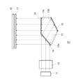
- FIG. 2 is a schematic cross-sectional view illustrating an overview of an image projection unit 10 according to the first embodiment.
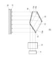
- FIG. 11 is a schematic cross-sectional view illustrating an overview of an image projection unit 10 according to a second embodiment.
- FIG. 11 is a schematic cross-sectional view illustrating an overview of an image projection unit 10 according to a third embodiment.
- FIG. 13 is a schematic cross-sectional view illustrating an overview of an image projection unit 10 according to a fourth embodiment.
- FIG. 1 is a schematic diagram for explaining the projection of a virtual image P using an image projection device 100 according to this embodiment.
- image light projected from the image projection device 100 is reflected by a windshield (display unit) WS and irradiated to the driver's viewpoint position.
- the driver visually recognizes the virtual image P formed on the extension (broken line direction) of the optical path from which the image light is incident.
- the image projection device 100 projects image light to form one virtual image P, but the number of virtual images P is not limited.
- the image projection device 100 includes an image projection unit 10, a first mirror 20, and a second mirror 30.
- each part is controlled using a control unit (not shown) that is connected to each part so that information can be communicated.
- the configuration of the control unit is not limited, but one example includes a CPU (Central Processing Unit) for information processing, a memory device, a recording medium, an information communication device, etc.
- the control unit controls the operation of each part according to a predetermined program, and sends information including an image (image information) to the image projection unit 10.
- the image projection unit 10 is a part that projects light containing an image onto the first mirror 20 as image light based on image information from the control unit. Details of the image projection unit 10 will be described later.
- the first mirror 20 is an optical member that reflects the image light arriving from the image irradiation unit 10 in the direction of the second mirror 30.
- the first mirror 20 is a concave reflecting mirror, but a flat or convex reflecting mirror may also be used.
- the first mirror 20 is made up of a curved surface, it is not limited to a surface with a constant curvature, and a paraboloid of revolution, an ellipsoid, a free-form surface mirror, etc. may be used.
- the second mirror 30 is an optical component that reflects the image light arriving from the first mirror 20 in the direction of the windshield WS.
- the second mirror 30 is a free-form mirror with an optically designed concave shape necessary for projecting the image light as a virtual image P.
- the reflective surfaces of the first mirror 20 and the second mirror 30 are designed to expand the light diameter in the driver's viewpoint direction in order to project the image light as a virtual image P through the windshield WS.
- the expansion of the light diameter in the viewpoint direction includes not only the case where the light diameter consistently expands after reflection, but also the case where the light diameter shrinks and expands after forming an image at an intermediate point.
- the combination of the first mirror 20 and the second mirror 30 has the function of projecting image light through the windshield WS, and corresponds to the projection optical unit in this invention.
- the optical path of the image light is depicted as a single straight arrow.
- the actual image light is displayed with a certain area in the image projection unit 10, and has a certain area in the direction perpendicular to the traveling direction.
- the image light is reflected by the first mirror 20, and its light diameter is reduced as it travels, and it may be intermediately imaged at an intermediate imaging position F (not shown) between the first mirror 20 and the second mirror 30.
- the windshield WS is a part that is provided in front of the driver's seat of the vehicle and transmits visible light.
- the windshield WS reflects the image light incident from the image projection device 100 toward the viewpoint and transmits light from outside the vehicle toward the viewpoint, and therefore corresponds to the display unit in the present invention.
- a combiner may be provided as a display unit separate from the windshield WS and reflect light from the image projection device 100 toward the viewpoint.
- the display unit is not limited to being located at the front of the vehicle, and may be located to the side or rear as long as it projects an image toward the viewpoint of the passenger.
- the virtual image P is an image that appears as if it is formed in space when the image light reflected by the windshield WS reaches the passenger's viewpoint (eyebox).
- the position where the virtual image P is formed is determined by the composite focal length of the projection optical unit included in the image projection device 100 and the windshield WS.
- the light source 11 is a member that irradiates the image display unit 18 with light via the primary lens 12, the light guide unit 13, the reflective polarizing unit 14, the reflector 15, the half-wave plate 16, and the diffuser 17.
- the light source 11 is, for example, a semiconductor light-emitting element such as an LED (Light Emitting Diode), and is arranged in a predetermined direction (the depth direction of the paper in FIG. 2).
- the light color of the light source 11 is not particularly limited, but in this embodiment, it is white as an example. Note that in this embodiment, the number of light sources 11 arranged is one row, but it may be two or more rows.
- the light source 11 is not limited to an LED, and may be a semiconductor laser, an organic EL (Electro Luminescence) element, etc.
- the primary lens 12 is an optical member arranged in the light emission direction of the multiple light sources 11, and has the function of concentrating the light emitted from the light sources 11 and emitting it as, for example, parallel light or light close to parallel light (hereinafter, both are collectively referred to as "approximately parallel light").
- the primary lens 12 is also extended along the arrangement direction of the multiple light sources 11.
- a TIR (Total Internal Reflection) lens is used, which has a refracting part in the center that refracts light and a reflecting part on both sides of the refracting part that reflects light.
- TIR Total Internal Reflection
- the light guide section 13 is an optical component made of a light-transmitting material through which light propagates.
- the cross section is a pentagon, with the first surface being the light entrance section 13a, the second surface being the light reflection section 13b, and the third surface being the light exit section 13c.
- the first surface which is the light entrance section 13a and the third surface which is the light exit section 13c are adjacent surfaces of the light guide section 13.
- the light incident portion 13a is the first surface through which the irradiated light from the light source 11 enters the light guide portion 13.
- the first surface, which is the light incident portion 13a is preferably a flat surface, and is provided at an angle with respect to the incident direction of the irradiated light.
- a reflective polarizing portion 14 is provided on the light incident portion 13a.
- the light reflecting portion 13b is the second surface where the irradiated light incident from the light incident portion 13a into the light guide portion 13 reaches and is reflected.
- a reflecting mirror 15 is provided on the light reflecting portion 13b.
- FIG. 2 shows an example where the reflecting mirror 15 is provided on the light reflecting portion 13b, if the irradiated light can be totally reflected due to the difference in refractive index between the light reflecting portion 13b and air, the reflecting mirror 15 may not be provided.
- the first surface which is the light incident portion 13a and the second surface which is the light reflecting portion 13b are arranged non-parallel to each other.
- the light exit portion 13c is a third surface that receives the irradiated light reflected by the light reflecting portion 13b and emits the irradiated light to the outside.
- the third surface which is the light exit portion 13c, is preferably a flat surface.
- the light exit portion 13c is provided with a half-wave plate 16.
- the light exit portion 13c is arranged parallel to the incident direction of the irradiated light to the light incident portion 13a, and an example is shown in which the reflected light reflected by the light reflecting portion 13b is incident at a substantially right angle, but the inclination angle of the light exit portion 13c with respect to the incident light and reflected light is not limited.
- the reflective polarizing unit 14 is an optical component provided at the light entrance portion 13a, which reflects polarized light in a first direction and transmits polarized light in a second direction perpendicular to the first direction.
- the polarization direction transmitted by the reflective polarizing unit 14 is not limited, and must match the polarization direction required for the backlight light ultimately irradiated to the image display unit 18. As an example, it may transmit polarized light in the horizontal direction in FIG. 2 (e.g., p-polarized light) and reflect polarized light perpendicular to the paper surface (e.g., s-polarized light).
- the reflective polarizing unit 14 is disposed at a predetermined angle with respect to the traveling direction of the light irradiated from the light source 11.
- the reflector 15 is an optical element provided in the light reflecting section 13b and reflects the irradiated light propagating through the light guide section 13.
- the reflector 15 is disposed at a predetermined angle with respect to the direction of travel of the light transmitted through the reflective polarizing section 14.
- the reflector 15 may totally reflect light due to the difference in refractive index between the material constituting the light guide section 13 and air, or a reflective film may be formed on the light reflecting section 13b using a metal or dielectric multilayer film to improve reflectivity, or a reflective sheet may be attached. Also, an example is shown here in which the light reflecting section 13b of the light guide section 13 is cut out at an angle for total reflection, but the reflection does not have to be total reflection.
- the half-wave plate 16 is provided in the light output section 13c and is an optical element made of a birefringent material with different refractive indices in the slow axis and the fast axis.
- the half-wave plate 16 is designed so that a phase difference of half the wavelength of the light occurs between the slow axis and the fast axis before the incident light is output.
- the slow axis and the fast axis of the half-wave plate 16 are arranged in a direction that differs by 45 degrees from the polarization direction of the reflected light reflected by the light reflecting section 13b.
- the half-wave plate 16 does not need to have a phase difference of exactly 50% with respect to the wavelength of the light, and can perform the function of rotating the polarization direction in the plane as long as it generates a phase difference close to 50%.
- the incident angle of the irradiation light incident on the half-wave plate 16 is not necessarily perpendicular to the half-wave plate 16, so it is preferable to use a half-wave plate 16 with small angle dependency.
- the diffuser 17 is disposed on the rear side of the image display unit 18 and is a member that diffuses and transmits backlight.
- the diffuser 17 diffuses the highly directional light deflected by the primary lens 12 and outputs it to the image display unit 18, so that the image display unit 18 is illuminated more uniformly. It is preferable to use an optical member as the diffuser 17 that diffuses and transmits the backlight irradiated from the reflective polarizing unit 14 and the half-wave plate 16 while maintaining the polarization direction of the backlight.
- the image display unit 18 functions as a spatial light modulation unit that receives backlight irradiated from the reflective polarizing unit 14 and the half-wave plate 16 from the rear side and emits light modulated by image information from the output surface.
- the specific configuration of the image display unit 18 is not limited, but as an example, a transmissive liquid crystal display device that transmits light incident from the rear side and emits it from the front side can be used. In a transmissive liquid crystal display device, only polarized light of a specific direction that is incident on the rear side is transmitted, so the polarization direction of the backlight light irradiated from the reflective polarizing unit 14 and the half-wave plate 16 is made to match the specific direction.
- the irradiation light irradiated from the light source 11 is unpolarized with no restriction on the polarization direction.
- the irradiation light irradiated from the light source 11 is incident on the primary lens 12 and collimated, and reaches the light entrance section 13a of the light guide section 13.
- the irradiation light incident on the light entrance section 13a is polarized in a first direction by the reflective polarizing section 14 in the direction of the diffuser plate 17, and is polarized in a second direction by the reflective polarizing section 14.
- the polarization of the irradiation light reflected by the reflective polarizing section 14 is polarized in the first direction through which the image display section 18 is transmitted.
- the polarization of the irradiation light that transmits through the reflective polarizing section 14 is polarized in a second direction that is approximately perpendicular to the first direction.
- the illumination light that passes through the reflective polarizing unit 14 is refracted due to the difference in refractive index between the first surface (light entrance unit 13a) and air, and travels in the direction of the light reflecting unit 13b.
- the illumination light that reaches the light reflecting unit 13b is reflected by the reflecting mirror 15 and travels in the direction of the light exit unit 13c.
- the illumination light that reaches the light exit unit 13c enters the half-wave plate 16, where the polarization direction is rotated 90 degrees, and enters the diffuser 17 as backlight light polarized in the first direction.
- the diffuser 17 diffuses and transmits the backlight light polarized in the first direction. As a result, the backlight light polarized in the first direction is uniformly illuminated on the back surface of the image display unit 18.
- the reflective polarizing unit 14 is disposed at an angle of 45 degrees with respect to the traveling direction of the light irradiated from the light source 11, and the traveling direction of the light reflected by the reflective polarizing unit 14 in the backlight is the same as that of the light reflected by the reflector 15 and transmitted through the half-wave plate 16.
- the angle of the reflective polarizing unit 14 with respect to the irradiated light is not limited, and the traveling direction of the light reflected by the reflective polarizing unit 14 and the light transmitted through the half-wave plate 16 may be different.
- the reflective polarizing section 14 provided on the first surface, which is the light entrance 13a, and the reflector 15 provided on the second surface, which is the light reflecting section 13b are arranged non-parallel.
- the normal direction of the first surface, which is the light entrance 13a differs from the normal direction of the second surface, which is the light reflecting section 13b, by a predetermined angle determined by the difference in refractive index between the material constituting the light guide section 13 and air.
- the reflected light reflected by the light reflecting section 13b is incident on the third surface, which is the light exit section 13c, at a substantially right angle.
- the traveling direction of the light incident from the light source 11 to the light entrance 13a and the traveling direction of the light reflected by the light reflecting section 13b are approximately at a right angle.
- a reflective polarizing section 14 is provided on the first surface, which is the light incident section 13a, and a reflector 15 is provided on the second surface, which is the light reflecting section 13b, but the reflective polarizing section 14 and reflector 15 are not built into the light guide section 13. This eliminates the need to construct the light guide section 13 from multiple members and bond them together, making it possible to reduce the number of parts, simplify the manufacturing process, and reduce weight.
- the light irradiated from the light source 11 is polarized in a first direction and reflected by the reflective polarizing section 14, and the light polarized in a second direction is transmitted through the reflective polarizing section 14 and reflected by the light reflecting section 13b to reach the light emitting section 13c, where the polarization direction is rotated 90 degrees by the half-wave plate 16 and converted to polarization in the first direction.
- the polarization direction of the backlight light that reaches the image display section 18 matches the polarization direction used for image display in the image display section 18, only a small amount of polarized components are absorbed by the image display section 18, making it possible to improve the light utilization efficiency.
- the third surface, which is the light exit portion 13c is parallel to the light incident direction, but in this embodiment, the third surface, which is the light exit portion 13c, is provided at an angle with respect to the incident direction of the irradiated light to the light incident portion 13a.
- the light emitted from the light source 11 is also incident on the primary lens 12 and collimated, and reaches the light entrance unit 13a of the light guide unit 13.
- the light incident on the light entrance unit 13a is polarized in the first direction and reflected by the reflective polarizing unit 14 toward the diffuser plate 17, and the light polarized in the second direction is transmitted through the reflective polarizing unit 14.
- the light transmitted through the reflective polarizing unit 14 is refracted due to the difference in refractive index between the first surface, which is the light entrance unit 13a, and air, and travels toward the light reflecting unit 13b.
- the light that reaches the light reflecting unit 13b is reflected by the reflector 15 and travels toward the light exit unit 13c.
- the light that reaches the light exit unit 13c is incident on the half-wave plate 16, where the polarization direction is rotated by 90 degrees, and enters the diffuser plate 17 as backlight light polarized in the first direction.
- the reflected light reflected by the light reflecting section 13b is incident on the third surface, which is the light exiting section 13c, at a predetermined inclination angle, and is refracted and travels in the direction of the diffuser 17. Therefore, depending on the relationship of the inclination angles of the first surface, which is the light entrance section 13a, the second surface, which is the light reflecting section 13b, and the third surface, which is the light exiting section 13c, the traveling direction of the backlight light that is emitted from the light exiting section 13c and transmitted through the half-wave plate 16 can be appropriately set. Also, in FIG.
- the traveling direction of the light reflected by the reflective polarizing section 14 in the backlight light is the same as that of the light reflected by the reflecting mirror 15 and transmitted through the half-wave plate 16, but the angle of the reflective polarizing section 14 with respect to the irradiation light is not limited, and the traveling direction of the light reflected by the reflective polarizing section 14 and the light transmitted through the half-wave plate 16 may be different.
- the reflected light reflected by the light reflecting unit 13b also enters the third surface, which is the light exiting unit 13c, at a predetermined inclination angle, and is refracted and travels toward the diffuser plate 17. Therefore, depending on the relationship between the inclination angles of the first surface, which is the light entrance unit 13a, the second surface, which is the light reflecting unit 13b, and the third surface, which is the light exiting unit 13c, the traveling direction of the backlight light that is emitted from the light exiting unit 13c and transmitted through the half-wave plate 16 can be appropriately set.
- the traveling direction of the light reflected by the reflective polarizing unit 14 in the backlight light is the same as that of the light reflected by the reflecting mirror 15 and transmitted through the half-wave plate 16, but the angle of the reflective polarizing unit 14 with respect to the irradiation light is not limited, and the traveling direction of the light reflected by the reflective polarizing unit 14 and the light transmitted through the half-wave plate 16 may be different.
- a fourth embodiment of the present invention will be described with reference to Fig. 5. Descriptions of contents overlapping with the first embodiment will be omitted.
- the image projection unit 10 of this embodiment is different in that the second surface, which is the light reflecting portion 13b, is configured as a curved surface.
- the second surface which is the light reflecting portion 13b, and the reflecting mirror 15 provided on the second surface are configured with curved surfaces.
- the curved shapes of the light reflecting portion 13b and the reflecting mirror 15 are not limited, but it is preferable that they have a curvature that can effectively focus the light reflected by the reflecting mirror 15 on the half-wave plate 16, as described below.
- FIG. 5 shows an example of the curved shapes of the light reflecting portion 13b and the reflecting mirror 15 in which the second surface protrudes and the reflecting surface has a concave shape, but the second surface may be recessed and the reflecting surface may have a convex shape.
- the irradiated light can be focused on the half-wave plate 16. Therefore, the area of the half-wave plate 16 is smaller than the area of the third surface, which is the light emitting portion 13c. This makes it possible to reduce the area of the half-wave plate 16. Furthermore, even if the area of the half-wave plate 16 is reduced, it is possible to satisfactorily convert polarized light in the second direction into polarized light in the first direction and irradiate it as backlight light.
- the irradiated light reflected by the reflector 15 and incident on the half-wave plate 16 is collected before reaching the diffuser 17, and reaches the diffuser 17 with an expanding light diameter.
- the light diameter of the backlight light irradiated from the diffuser 17 to the image display unit 18 also expands, making it possible to irradiate a wider range evenly.
- FIG. 5 shows an example in which the irradiated light is collected between the reflector 15 and the half-wave plate 16. In this case, it is preferable to ensure a distance over which the light diameter expands between the time when the irradiated light reaches the diffuser 17 after being collected.
- the light may also be collected inside the half-wave plate 16. In this case, the area of the half-wave plate 16 can be minimized.
- image projection device 10 ... image irradiation section 11... light source 12... primary lens 13... light guide section 13a... light entrance section 13b... light reflection section 13c... light exit section 14... reflective polarizing section 15... reflecting mirror 16... half-wave plate 17... diffusion plate 18... image display section 20... first mirror 30... second mirror
Landscapes
- Engineering & Computer Science (AREA)
- Physics & Mathematics (AREA)
- Automation & Control Theory (AREA)
- General Physics & Mathematics (AREA)
- Optics & Photonics (AREA)
- Human Computer Interaction (AREA)
- Transportation (AREA)
- Mechanical Engineering (AREA)
- Devices For Indicating Variable Information By Combining Individual Elements (AREA)
- Optical Elements Other Than Lenses (AREA)
- Control Of Driving Devices And Active Controlling Of Vehicle (AREA)
Abstract
照射光の利用効率を高めることが可能な光学部材および画像投影装置を提供する。内部を光が伝搬する導光体部(13)と、導光体部(13)の第1面に設けられ、光が入射する光入射部(13a)と、導光体部(13)の第2面に設けられ、光入射部(13a)から入射した光を反射光として反射する光反射部(13b)と、導光体部(13)の第3面に設けられ、反射光を出射する光出射部(13c)を備え、光入射部(13a)には、第1方向の偏光を反射し、第1方向と交わる第2方向の偏光を透過する反射型偏光部(14)が設けられ、光出射部(13c)には、反射光の偏光方向を90度回転させる二分の一波長板(16)が設けられている光学部材。
Description
本発明は、光学部材および画像投影装置に関する。
従来から、車両内に各種情報を表示する装置として、アイコンを点灯表示する計器盤が用いられている。また、表示する情報量の増加とともに、計器盤に画像表示装置を埋め込むことや、計器盤全体を画像表示装置で構成することも提案されている。
しかし、計器盤は車両のフロントガラス(ウィンドシールド)より下方に位置しているため、計器盤に表示された情報を運転者等の搭乗者が視認するには、運転中に視線を下方に移動させる必要があり好ましくない。そこで、フロントガラスに画像を投影して、搭乗者が車両の前方を視認したときに情報を読み取れるようにするヘッドアップディスプレイ(以下HUD:Head Up Display)のような画像投影装置が提案されている(例えば、特許文献1,2を参照)。
特許文献1,2の画像投影装置は、画像照射部が画像を含んだ照射光を照射し、自由曲面ミラー等で照射光を反射させて、ウィンドシールド等の表示部を介して空間中に画像が結像するように搭乗者の視点の位置に到達させる。これにより、搭乗者は視点に入射した照射光によって、奥行き方向における結像位置に画像が表示されているように認識することができる。
このような従来の画像投影装置では、液晶表示装置等の画像表示部を用いて投影画像を表示し、画像表示部の背面側から照射光を照射して画像光を投影している。しかし、液晶表示装置等の画像表示部では、特定方向の偏光のみを透過するため、無偏光の照射光が入射した場合には、特定方向以外の偏光は画像の投影に利用されず光の利用効率が低下する。
そこで本発明は、上記従来の問題点に鑑みなされたものであり、照射光の利用効率を高めることが可能な光学部材および画像投影装置を提供することを目的とする。
上記課題を解決するために、本発明の光学部材は、内部を光が伝搬する導光体部と、前記導光体部の第1面に設けられ、前記光が入射する光入射部と、前記導光体部の第2面に設けられ、前記光入射部から入射した前記光を反射光として反射する光反射部と、前記導光体部の第3面に設けられ、前記反射光を出射する光出射部を備え、前記光入射部には、第1方向の偏光を反射し、前記第1方向と交わる第2方向の偏光を透過する反射型偏光部が設けられ、前記光出射部には、前記反射光の偏光方向を90度回転させる二分の一波長板が設けられていることを特徴とする。
このような本発明の光学部材では、光源から照射された光は反射型偏光部で第1方向の偏光が反射され、第2方向の偏光は反射型偏光部を透過して光反射部で反射されて光出射部に到達し、二分の一波長板で偏光方向が90度回転されて第1方向の偏光に変換される。これにより、光源からの無偏光の光を同じ方向の偏光にして面積を拡大して照射し、照射光の利用効率を高めることが可能となる。
また、本発明の一態様では、前記光は前記光入射部に入射して屈折され、前記光反射部に到達する。
また、本発明の一態様では、前記第1面および前記第3面は、前記導光体部の隣り合う面である。
また、本発明の一態様では、前記第1面および前記第3面は、前記光入射部への前記光の入射方向に対して傾斜して設けられている。
また、本発明の一態様では、前記第1面は、前記光入射部への前記光の入射方向に対して傾斜して設けられ、前記第3面は、前記入射方向と平行に配置されている。
また、本発明の一態様では、前記第1面と前記第2面は非平行に配置され、前記反射光は前記光出射部に略直角に入射する。
また、本発明の一態様では、前記第2面が曲面で構成されている。
また、上記課題を解決するために、本発明の画像投影は、上記何れか一つに記載の光学部材と、前記光入射部に対して光を照射する光源と、前記反射型偏光部で反射された前記第1方向の偏光、および前記光出射部から照射された光が入射し、画像光を照射する画像照射部と、虚像を表示するための表示部に対して前記画像光を投影する投影光学部とを備えることを特徴とする。
本発明では、照射光の利用効率を高めることが可能な光学部材および画像投影装置を提供することができる。
(第1実施形態)
以下、本発明の実施形態について、図面を参照して詳細に説明する。各図面に示される同一または同等の構成要素、部材、処理には同一の符号を付すものとし、適宜重複した説明は省略する。以下の説明では、本発明に係る画像投影装置100を、車両等に搭載されるHUDに適用した形態を例示して説明する。図1は、本実施形態に係る画像投影装置100を用いた虚像Pの投影を説明する模式図である。図1に示すように、画像投影装置100から投影された画像光は、ウィンドシールド(表示部)WSで反射されて運転者の視点位置に照射される。運転者は、画像光が入射してきた光路の延長上(破線方向)に結像された虚像Pを視認する。本実施形態では画像投影装置100が画像光を投影して一つの虚像Pが結像される例を示しているが、虚像Pの数は限定されない。
以下、本発明の実施形態について、図面を参照して詳細に説明する。各図面に示される同一または同等の構成要素、部材、処理には同一の符号を付すものとし、適宜重複した説明は省略する。以下の説明では、本発明に係る画像投影装置100を、車両等に搭載されるHUDに適用した形態を例示して説明する。図1は、本実施形態に係る画像投影装置100を用いた虚像Pの投影を説明する模式図である。図1に示すように、画像投影装置100から投影された画像光は、ウィンドシールド(表示部)WSで反射されて運転者の視点位置に照射される。運転者は、画像光が入射してきた光路の延長上(破線方向)に結像された虚像Pを視認する。本実施形態では画像投影装置100が画像光を投影して一つの虚像Pが結像される例を示しているが、虚像Pの数は限定されない。
図1に示すように画像投影装置100は、画像照射部10と、第1ミラー20と、第2ミラー30を備えている。画像投影装置100では、各部と情報通信可能に接続された制御部(図示省略)を用いて各部を制御している。制御部の構成は限定されないが、一例として情報処理を行うためのCPU(Central Processing Unit)や、メモリ装置、記録媒体、情報通信装置等を備えるものが挙げられる。制御部は、予め定められたプログラムに従って各部の動作を制御し、画像を含んだ情報(画像情報)を画像照射部10に送出する。
画像照射部10は、制御部からの画像情報に基づいて、画像を含んだ光を画像光として第1ミラー20に対して照射する部分である。画像照射部10の詳細については後述する。
第1ミラー20は、画像照射部10から到達した画像光を第2ミラー30方向に反射する光学部材である。図1に示した例では第1ミラー20を凹面の反射鏡とした例を示しているが、平面または凸面の反射鏡を用いるとしてもよい。また、第1ミラー20を曲面で構成する場合には、曲率が一定なものに限定されず、回転放物面や楕円面、自由曲面ミラー等を用いることができる。
第2ミラー30は、第1ミラー20から到達した画像光をウィンドシールドWS方向に反射する光学部材である。図1に示した例では、第2ミラー30として画像光を虚像Pとして投影するために必要な光学設計された凹面形状の自由曲面ミラーを示している。
第1ミラー20および第2ミラー30の反射面は、ウィンドシールドWSを介して画像光を虚像Pとして投影するために、運転者の視点方向に光径が拡大するように設計されている。ここで、視点方向に光径が拡大するとは、反射後に光径が一貫して拡大する場合だけでなく、光径が縮小して中間地点において結像した後に拡大する場合も含む。第1ミラー20および第2ミラー30の組み合わせは、ウィンドシールドWSを介して画像光を投影する機能を有しており、本発明における投影光学部に相当している。
図1では、画像光の光路を一本の直線矢印として描いている。しかし、実際の画像光は、画像照射部10において所定の面積で表示されたものであり、進行方向に垂直な方向に所定の面積をもっている。また、画像光は、第1ミラー20で反射されて光径が縮小されながら進行し、第1ミラー20と第2ミラー30の間の中間結像位置F(図示省略)において中間結像されるとしてもよい。
ウィンドシールドWSは、車両の運転席前方に設けられて可視光を透過する部分である。ウィンドシールドWSは、車両の内側面では画像投影装置100から入射した画像光を視点方向に対して反射し、車両の外部からの光を視点方向に対して透過するため、本発明における表示部に相当している。ここでは表示部としてウィンドシールドWSを用いた例を示したが、ウィンドシールドWSとは別に表示部としてコンバイナーを用意し、画像投影装置100からの光を視点方向に反射するとしてもよい。また、車両の前方に位置するものに限定されず、搭乗者の視点に対して画像を投影するものであれば側方や後方に配置するとしてもよい。
虚像Pは、ウィンドシールドWSで反射された画像光が搭乗者の視点(アイボックス)に到達した際に、空間中に結像されたように表示される画像である。虚像Pが結像される位置は、画像投影装置100に含まれる投影光学部とウィンドシールドWSの合成焦点距離によって決まる。
図2は、本実施形態に係る画像照射部10の概要を説明する模式断面図である。図2に示すように、本実施形態の画像照射部10は、光源11と、プライマリーレンズ12と、導光体部13と、反射型偏光部14と、反射鏡15と、二分の一波長板16と、拡散板17と、画像表示部18を備えている。図2では、反射型偏光部14、反射鏡15および二分の一波長板16と導光体部13との間に空間が示されているが、空間を設けず導光体部13の表面に各部を直接貼り合わせることが好ましい。また、導光体部13は複数の面を有しており、光入射部13a、光反射部13b、光出射部13cを備えている。
光源11は、プライマリーレンズ12、導光体部13、反射型偏光部14、反射鏡15、二分の一波長板16、拡散板17を介して照射光を画像表示部18に照射する部材である。光源11は、一例としてはLED(Light Emitting Diode:発光ダイオード)等の半導体発光素子であり、予め定められた方向(図2の紙面奥行き方向)に配列されている。光源11の発光色は特に限定されないが、本実施形態では一例として白色としている。なお、本実施形態では光源11の配列数を1列としているが、2列以上であってもよい。また光源11はLEDに限らず半導体レーザや有機EL(Electro Luminescence)素子等であってもよい。
プライマリーレンズ12は、複数の光源11の光出射方向に配置され、光源11から照射された照射光を集光し、例えば平行光、あるいは平行光に近い光(以下、両者を併せて「略平行光」という)として出射する機能を有する光学部材である。またプライマリーレンズ12は、複数の光源11の配列方向に沿って延伸されている。本実施形態ではプライマリーレンズ12の一例として、中央に光を屈折する屈折部が設けられ、屈折部の両側に光を反射する反射部が設けられたTIR(Total Internal Reflection)レンズを用いている。図2ではプライマリーレンズ12として光源11の配列方向に延伸された形状を示しているが、光源11毎に複数のコリメートレンズを設けるとしてもよい。また、光源11からの光を略平行光にすることができればレンズに限定されず、リフレクタとレンズの組み合わせやリフレクタ単体で略平行光とする構成を採用してもよい。
導光体部13は、透光性材料で構成され内部を光が伝搬する光学部材である。導光体部13の形状は限定されないが、図2に示した例では断面が五角形を為して、第1面が光入射部13aとされ、第2面が光反射部13bとされ、第3面が光出射部13cとされている。図2に示したように、光入射部13aである第1面と、光出射部13cである第3面は、導光体部13の隣り合う面である。
光入射部13aは、光源11からの照射光が導光体部13に入射する第1面である。光入射部13aである第1面は平坦な面であることが好ましく、照射光の入射方向に対して傾斜して設けられている。また、光入射部13aには反射型偏光部14が設けられている。
光反射部13bは、光入射部13aから導光体部13内に入射した照射光が到達し、反射される第2面である。光反射部13bには反射鏡15が設けられている。図2では光反射部13bに反射鏡15を設けた例を示したが、光反射部13bと空気の屈折率差により照射光を全反射出来る場合には、反射鏡15を設けない構成としてもよい。また、光入射部13aである第1面と、光反射部13bである第2面は非平行に配置されている。
光出射部13cは、光反射部13bで反射された照射光が到達し、照射光を外部に出射する第3面である。光出射部13cである第3面は平坦な面であることが好ましい。光出射部13cには二分の一波長板16が設けられている。図2では、光出射部13cは光入射部13aに対する照射光の入射方向と平行に配置されており、光反射部13bで反射された反射光が略直角に入射する例を示しているが、入射光と反射光に対する光出射部13cの傾斜角度は限定されない。
反射型偏光部14は、光入射部13aに設けられて、第1方向の偏光を反射し、第1方向に直交する第2方向の偏光を透過する光学部材である。反射型偏光部14が透過する偏光方向は限定されず、最終的に画像表示部18に対して照射されるバックライト光に要求される偏光方向に適合させる必要がある。一例としては図2における横方向の偏光(例えばp偏光)を透過し、紙面に垂直な方向の偏光(例えばs偏光)を反射するとしてもよい。反射型偏光部14は、光源11から照射される光の進行方向に対して所定角度だけ傾斜して配置されている。
反射鏡15は、光反射部13bに設けられて、導光体部13内を伝搬してきた照射光を反射する光学部材である。反射鏡15は、反射型偏光部14を透過した光の進行方向に対して所定角度だけ傾斜して配置されている。反射鏡15は、導光体部13を構成する材料と空気の屈折率差によって光が全反射するとしてもよく、反射率を向上させるために光反射部13bに金属や誘電体多層膜で反射膜を形成するとしてもよく、反射シートを貼り付けるとしてもよい。また、ここでは導光体部13の光反射部13bとして、全反射する角度で切り出された例を示しているが、反射は全反射でなくともよい。
二分の一波長板16は、光出射部13cに設けられ、スロー軸とファスト軸における屈折率が異なる複屈折材料で構成された光学部材である。また、二分の一波長板16は、入射した光が出射するまでに光の波長の半分だけスロー軸とファスト軸で位相差が生じるように設計されている。また、二分の一波長板16のスロー軸とファスト軸は、光反射部13bで反射された反射光の偏光方向に対して45度異なる向きに配置されている。また、二分の一波長板16は、光の波長に対し正確に50%の位相差である必要はなく、50%に近い位相差を生じさせるものであれば、面内における偏光方向の回転という機能を発揮することができる。二分の一波長板16に入射する照射光は、二分の一波長板16に対する入射角度が垂直とは限らないため、角度依存性の小さな二分の一波長板16を用いることが好ましい。
拡散板17は、画像表示部18の背面側に配置され、バックライト光を拡散して透過する部材である。拡散板17は、プライマリーレンズ12で偏向した指向性の高い光を拡散させて画像表示部18に出射し、画像表示部18がより均一に照明されるように機能する。拡散板17としては、反射型偏光部14および二分の一波長板16から照射されたバックライト光の偏光方向を維持したまま拡散して透過する光学部材を用いることが好ましい。
画像表示部18は、反射型偏光部14および二分の一波長板16から照射されたバックライト光が背面から入射し、画像情報によって変調した光を出射面から出射する空間光変調部として機能する。画像表示部18の具体的な構成は限定されないが、一例としては、背面から入射した光を透過して表面から出射する透過型液晶表示装置を用いることができる。透過型液晶表示装置では、裏面側に入射した所定方向の偏光のみが透過されるため、反射型偏光部14および二分の一波長板16から照射されたバックライト光の偏光方向を当該所定方向と一致させる。
上述した画像照射部10では、光源11から照射された照射光は偏光方向が限定されていない無偏光である。光源11から照射された照射光は、プライマリーレンズ12に入射してコリメートされ、導光体部13の光入射部13aに到達する。光入射部13aに入射した照射光は、第1方向の偏光が反射型偏光部14で拡散板17方向に反射され、第2方向の偏光が反射型偏光部14を透過する。ここで、反射型偏光部14で反射される照射光の偏光は、画像表示部18が透過する第1方向に偏光している。また、反射型偏光部14を透過する照射光の偏光は、第1方向にほぼ直交する第2方向に偏光している。
反射型偏光部14を透過した照射光は、光入射部13aである第1面と空気の屈折率差により屈折され、光反射部13b方向に進行する。光反射部13bに到達した照射光は、反射鏡15で反射されて光出射部13c方向に進行する。光出射部13cに到達した照射光は、二分の一波長板16に入射して偏光方向が90度回転されて、第1方向に偏光したバックライト光として拡散板17に入射する。拡散板17では、第1方向に偏光したバックライト光は拡散および透過される。これにより、画像表示部18の背面には第1方向に偏光したバックライト光が均一に照射される。
図2に示した例では、反射型偏光部14は光源11から照射された光の進行方向に対して45度傾斜して配置されており、バックライト光における反射型偏光部14で反射された光と、反射鏡15で反射され二分の一波長板16を透過した光の進行方向が同じである。しかし、反射型偏光部14の照射光に対する角度は限定されず、反射型偏光部14で反射された光と、二分の一波長板16を透過した光の進行方向が異なっているとしてもよい。
また、光入射部13aでは導光体部13を構成する材料と空気の屈折率差によって照射光が屈折するため、光入射部13aである第1面に設けられた反射型偏光部14と、光反射部13bである第2面に設けられた反射鏡15は、非平行に配置されている。また、光入射部13aである第1面の法線方向と、光反射部13bである第2面の法線方向は、導光体部13を構成する材料と空気の屈折率差で決まる所定の角度だけ異なっている。また、光反射部13bで反射された反射光は、光出射部13cである第3面に略直角に入射する。また、光源11から光入射部13aに入射する光の進行方向と、光反射部13bで反射された光の進行方向は略直角となっている。
本実施形態の光学部材では、光入射部13aである第1面に反射型偏光部14を設け、光反射部13bである第2面に反射鏡15を設けているが、反射型偏光部14および反射鏡15を導光体部13の内部に作り込んだ構成とはしていない。これにより、導光体部13を複数の部材で構成して貼り合わせる必要がなく、部品点数の低減や製造工程の簡略化、および軽量化を図ることができる。
上述したように、本実施形態の光学部材およびこれを用いた画像投影装置100では、光源11から照射された照射光は反射型偏光部14で第1方向の偏光が反射され、第2方向の偏光は反射型偏光部14を透過して光反射部13bで反射されて光出射部13cに到達し、二分の一波長板16で偏光方向が90度回転されて第1方向の偏光に変換される。また、画像表示部18に到達するバックライト光の偏光方向は、画像表示部18での画像表示に用いられる偏光方向と一致しているため、画像表示部18で吸収されてしまう偏光成分は少なく、光の利用効率を向上させることが可能となる。
(第2実施形態)
次に、本発明の第2実施形態について図3を用いて説明する。第1実施形態と重複する内容は説明を省略する。第1実施形態では、光出射部13cである第3面を光の入射方向と平行としたが、本実施形態では光出射部13cである第3面は、光入射部13aへの照射光の入射方向に対して傾斜して設けられている。
次に、本発明の第2実施形態について図3を用いて説明する。第1実施形態と重複する内容は説明を省略する。第1実施形態では、光出射部13cである第3面を光の入射方向と平行としたが、本実施形態では光出射部13cである第3面は、光入射部13aへの照射光の入射方向に対して傾斜して設けられている。
本実施形態の画像照射部10でも、光源11から照射された照射光は、プライマリーレンズ12に入射してコリメートされ、導光体部13の光入射部13aに到達する。光入射部13aに入射した照射光は、第1方向の偏光が反射型偏光部14で拡散板17方向に反射され、第2方向の偏光が反射型偏光部14を透過する。反射型偏光部14を透過した照射光は、光入射部13aである第1面と空気の屈折率差により屈折され、光反射部13b方向に進行する。光反射部13bに到達した照射光は、反射鏡15で反射されて光出射部13c方向に進行する。光出射部13cに到達した照射光は、二分の一波長板16に入射して偏光方向が90度回転されて、第1方向に偏光したバックライト光として拡散板17に入射する。
ここで、光反射部13bで反射された反射光は、光出射部13cである第3面に所定の傾斜角度で入射し、屈折されて拡散板17方向に進行する。したがって、光入射部13aである第1面、光反射部13bである第2面、光出射部13cである第3面の傾斜角度の関係によって、光出射部13cから出射されて二分の一波長板16を透過するバックライト光の進行方向を適切に設定することができる。また、図3ではバックライト光における反射型偏光部14で反射された光と、反射鏡15で反射され二分の一波長板16を透過した光の進行方向が同じである例を示したが、反射型偏光部14の照射光に対する角度は限定されず、反射型偏光部14で反射された光と、二分の一波長板16を透過した光の進行方向が異なっているとしてもよい。
(第3実施形態)
次に、本発明の第3実施形態について図4を用いて説明する。第1実施形態と重複する内容は説明を省略する。第2実施形態では、光出射部13cである第3面を光反射部13b方向に傾斜させた例を示したが、図4に示したように本実施形態の画像照射部10では、光出射部13cである第3面を光反射部13bとは反対方向に傾斜させている点が異なっている。
次に、本発明の第3実施形態について図4を用いて説明する。第1実施形態と重複する内容は説明を省略する。第2実施形態では、光出射部13cである第3面を光反射部13b方向に傾斜させた例を示したが、図4に示したように本実施形態の画像照射部10では、光出射部13cである第3面を光反射部13bとは反対方向に傾斜させている点が異なっている。
本実施形態の画像照射部10でも、光反射部13bで反射された反射光は、光出射部13cである第3面に所定の傾斜角度で入射し、屈折されて拡散板17方向に進行する。したがって、光入射部13aである第1面、光反射部13bである第2面、光出射部13cである第3面の傾斜角度の関係によって、光出射部13cから出射されて二分の一波長板16を透過するバックライト光の進行方向を適切に設定することができる。また、図4ではバックライト光における反射型偏光部14で反射された光と、反射鏡15で反射され二分の一波長板16を透過した光の進行方向が同じである例を示したが、反射型偏光部14の照射光に対する角度は限定されず、反射型偏光部14で反射された光と、二分の一波長板16を透過した光の進行方向が異なっているとしてもよい。
(第4実施形態)
次に、本発明の第4実施形態について図5を用いて説明する。第1実施形態と重複する内容は説明を省略する。第1実施形態では、光反射部13bを平坦面で構成した例を示したが、図5に示したように本実施形態の画像照射部10では、光反射部13bである第2面を曲面で構成する点が異なっている。
次に、本発明の第4実施形態について図5を用いて説明する。第1実施形態と重複する内容は説明を省略する。第1実施形態では、光反射部13bを平坦面で構成した例を示したが、図5に示したように本実施形態の画像照射部10では、光反射部13bである第2面を曲面で構成する点が異なっている。
図5に示したように、光反射部13bである第2面と、第2面に設けられた反射鏡15は、曲面で構成されている。光反射部13bと反射鏡15の曲面形状は限定されないが、後述するように反射鏡15で反射された光を二分の一波長板16に効果的に集光できる曲率を有することが好ましい。また、図5では光反射部13bと反射鏡15の曲面形状として第2面が突出して反射面が凹形状となる例を示しているが、第2面が窪んで反射面を凸形状としてもよい。
図5に示した光反射部13bと反射鏡15の反射面を凹形状とした場合には、二分の一波長板16に対して照射光を集光することができる。よって、二分の一波長板16の面積は、光出射部13cである第3面の面積よりも小さくなっている。これにより、二分の一波長板16の面積を小さくすることが可能となる。また、二分の一波長板16の面積を小さくしても、第2方向の偏光を良好に第1方向の偏光に変換してバックライト光として照射することができる。
また、図5に示したように、反射鏡15で反射されて二分の一波長板16に入射した照射光は、拡散板17に到達する前に集光され、光径が拡大しながら拡散板17に到達している。これにより、拡散板17から画像表示部18に照射されるバックライト光も光径が拡大し、より広い範囲に均一に光を照射することが可能となる。図5では、反射鏡15と二分の一波長板16の間において照射光が集光された例を示している。この場合には、集光された後に拡散板17に照射光が到達する間に光径が拡がる距離を確保することができて好ましい。また、二分の一波長板16の内部において集光されるとしてもよい。この場合には、二分の一波長板16の面積を最小化することができる。
本発明は上述した各実施形態に限定されるものではなく、請求項に示した範囲で種々の変更が可能であり、異なる実施形態にそれぞれ開示された技術的手段を適宜組み合わせて得られる実施形態についても本発明の技術的範囲に含まれる。
本国際出願は、2023年3月23日に出願された日本国特許出願である特願2023-047394号に基づく優先権を主張するものであり、当該日本国特許出願である特願2023-047394号の全内容は、本国際出願に援用される。
本発明の特定の実施の形態についての上記説明は、例示を目的として提示したものである。それらは、網羅的であったり、記載した形態そのままに本発明を制限したりすることを意図したものではない。数多くの変形や変更が、上記の記載内容に照らして可能であることは当業者に自明である。
100…画像投影装置
10…画像照射部
11…光源
12…プライマリーレンズ
13…導光体部
13a…光入射部
13b…光反射部
13c…光出射部
14…反射型偏光部
15…反射鏡
16…二分の一波長板
17…拡散板
18…画像表示部
20…第1ミラー
30…第2ミラー
10…画像照射部
11…光源
12…プライマリーレンズ
13…導光体部
13a…光入射部
13b…光反射部
13c…光出射部
14…反射型偏光部
15…反射鏡
16…二分の一波長板
17…拡散板
18…画像表示部
20…第1ミラー
30…第2ミラー
Claims (8)
- 内部を光が伝搬する導光体部と、
前記導光体部の第1面に設けられ、前記光が入射する光入射部と、
前記導光体部の第2面に設けられ、前記光入射部から入射した前記光を反射光として反射する光反射部と、
前記導光体部の第3面に設けられ、前記反射光を出射する光出射部を備え、
前記光入射部には、第1方向の偏光を反射し、前記第1方向と交わる第2方向の偏光を透過する反射型偏光部が設けられ、
前記光出射部には、前記反射光の偏光方向を90度回転させる二分の一波長板が設けられていることを特徴とする光学部材。 - 請求項1に記載の光学部材であって、
前記光は前記光入射部に入射して屈折され、前記光反射部に到達することを特徴とする光学部材。 - 請求項1に記載の光学部材であって、
前記第1面および前記第3面は、前記導光体部の隣り合う面であることを特徴とする光学部材。 - 請求項3に記載の光学部材であって、
前記第1面および前記第3面は、前記光入射部への前記光の入射方向に対して傾斜して設けられていることを特徴とする光学部材。 - 請求項3に記載の光学部材であって、
前記第1面は、前記光入射部への前記光の入射方向に対して傾斜して設けられ、
前記第3面は、前記入射方向と平行に配置されていることを特徴とする光学部材。 - 請求項5に記載の光学部材であって、
前記第1面と前記第2面は非平行に配置され、
前記反射光は前記光出射部に略直角に入射することを特徴とする光学部材。 - 請求項1に記載の光学部材であって、
前記第2面が曲面で構成されていることを特徴とする光学部材。 - 請求項1から7の何れか一つに記載の光学部材と、
前記光入射部に対して光を照射する光源と、
前記反射型偏光部で反射された前記第1方向の偏光、および前記光出射部から照射された光が入射し、画像光を照射する画像照射部と、
虚像を表示するための表示部に対して前記画像光を投影する投影光学部とを備えることを特徴とする画像投影装置。
Applications Claiming Priority (2)
| Application Number | Priority Date | Filing Date | Title |
|---|---|---|---|
| JP2023-047394 | 2023-03-23 | ||
| JP2023047394A JP2024136311A (ja) | 2023-03-23 | 2023-03-23 | 光学部材および画像投影装置 |
Publications (1)
| Publication Number | Publication Date |
|---|---|
| WO2024195752A1 true WO2024195752A1 (ja) | 2024-09-26 |
Family
ID=92841571
Family Applications (1)
| Application Number | Title | Priority Date | Filing Date |
|---|---|---|---|
| PCT/JP2024/010421 Ceased WO2024195752A1 (ja) | 2023-03-23 | 2024-03-18 | 光学部材および画像投影装置 |
Country Status (2)
| Country | Link |
|---|---|
| JP (1) | JP2024136311A (ja) |
| WO (1) | WO2024195752A1 (ja) |
Citations (3)
| Publication number | Priority date | Publication date | Assignee | Title |
|---|---|---|---|---|
| JPH07318861A (ja) * | 1994-05-19 | 1995-12-08 | Canon Inc | 板状偏光素子、該板状偏光素子を用いた偏光照明装置および前記板状偏光素子を用いたプロジェクター |
| WO2012071167A1 (en) * | 2010-11-22 | 2012-05-31 | 3M Innovative Properties Company | Hybrid daylight-coupled backlights for sunlight viewable displays |
| JP2018004673A (ja) * | 2016-06-27 | 2018-01-11 | 日本精機株式会社 | 照明装置 |
-
2023
- 2023-03-23 JP JP2023047394A patent/JP2024136311A/ja active Pending
-
2024
- 2024-03-18 WO PCT/JP2024/010421 patent/WO2024195752A1/ja not_active Ceased
Patent Citations (3)
| Publication number | Priority date | Publication date | Assignee | Title |
|---|---|---|---|---|
| JPH07318861A (ja) * | 1994-05-19 | 1995-12-08 | Canon Inc | 板状偏光素子、該板状偏光素子を用いた偏光照明装置および前記板状偏光素子を用いたプロジェクター |
| WO2012071167A1 (en) * | 2010-11-22 | 2012-05-31 | 3M Innovative Properties Company | Hybrid daylight-coupled backlights for sunlight viewable displays |
| JP2018004673A (ja) * | 2016-06-27 | 2018-01-11 | 日本精機株式会社 | 照明装置 |
Also Published As
| Publication number | Publication date |
|---|---|
| JP2024136311A (ja) | 2024-10-04 |
Similar Documents
| Publication | Publication Date | Title |
|---|---|---|
| JP6663891B2 (ja) | バックライトユニットおよびヘッドアップディスプレイ装置 | |
| JP6036437B2 (ja) | ヘッドアップディスプレイ装置 | |
| CN113924521B (zh) | 图像显示装置 | |
| WO2014132817A1 (ja) | ヘッドアップディスプレイ装置 | |
| WO2024111398A1 (ja) | 画像投影装置 | |
| US20190004314A1 (en) | Head-up display for vehicle | |
| JP6600742B2 (ja) | 表示装置及び車両用ヘッドアップディスプレイ装置 | |
| WO2024195752A1 (ja) | 光学部材および画像投影装置 | |
| CN115903302B (zh) | 背光模组、抬头显示装置以及交通工具 | |
| WO2024195751A1 (ja) | 画像投影装置 | |
| JP7795400B2 (ja) | 画像投影装置 | |
| JP2018163260A (ja) | 画像表示装置、虚像表示装置、移動体 | |
| WO2024162164A1 (ja) | 画像投影装置 | |
| JP2025022146A (ja) | 画像投影装置 | |
| JP2025020699A (ja) | 画像投影装置 | |
| JP2025073922A (ja) | 画像投影装置 | |
| WO2025154556A1 (ja) | 画像投影装置 | |
| JP2025020696A (ja) | 偏光変換素子および画像投影装置 | |
| WO2024190460A1 (ja) | 画像投影装置 | |
| WO2024190458A1 (ja) | 画像投影装置 | |
| JP7712170B2 (ja) | 画像投影装置 | |
| JP2024065775A (ja) | 画像投影装置 | |
| JP2025075870A (ja) | 画像投影装置 | |
| WO2024135587A1 (ja) | 画像投影装置 | |
| JP2024113607A (ja) | 画像投影装置 |
Legal Events
| Date | Code | Title | Description |
|---|---|---|---|
| 121 | Ep: the epo has been informed by wipo that ep was designated in this application |
Ref document number: 24774888 Country of ref document: EP Kind code of ref document: A1 |
|
| NENP | Non-entry into the national phase |
Ref country code: DE |
|
| 122 | Ep: pct application non-entry in european phase |
Ref document number: 24774888 Country of ref document: EP Kind code of ref document: A1 |