WO2024195606A1 - 光吸収異方性膜、積層体、複合レンズ、仮想現実表示装置 - Google Patents
光吸収異方性膜、積層体、複合レンズ、仮想現実表示装置 Download PDFInfo
- Publication number
- WO2024195606A1 WO2024195606A1 PCT/JP2024/009334 JP2024009334W WO2024195606A1 WO 2024195606 A1 WO2024195606 A1 WO 2024195606A1 JP 2024009334 W JP2024009334 W JP 2024009334W WO 2024195606 A1 WO2024195606 A1 WO 2024195606A1
- Authority
- WO
- WIPO (PCT)
- Prior art keywords
- film
- laminate
- anisotropic film
- optically
- absorptive
- Prior art date
- Legal status (The legal status is an assumption and is not a legal conclusion. Google has not performed a legal analysis and makes no representation as to the accuracy of the status listed.)
- Ceased
Links
Images









Classifications
-
- G—PHYSICS
- G02—OPTICS
- G02B—OPTICAL ELEMENTS, SYSTEMS OR APPARATUS
- G02B5/00—Optical elements other than lenses
- G02B5/30—Polarising elements
- G02B5/3016—Polarising elements involving passive liquid crystal elements
-
- B—PERFORMING OPERATIONS; TRANSPORTING
- B32—LAYERED PRODUCTS
- B32B—LAYERED PRODUCTS, i.e. PRODUCTS BUILT-UP OF STRATA OF FLAT OR NON-FLAT, e.g. CELLULAR OR HONEYCOMB, FORM
- B32B7/00—Layered products characterised by the relation between layers; Layered products characterised by the relative orientation of features between layers, or by the relative values of a measurable parameter between layers, i.e. products comprising layers having different physical, chemical or physicochemical properties; Layered products characterised by the interconnection of layers
- B32B7/02—Physical, chemical or physicochemical properties
- B32B7/023—Optical properties
-
- G—PHYSICS
- G02—OPTICS
- G02B—OPTICAL ELEMENTS, SYSTEMS OR APPARATUS
- G02B17/00—Systems with reflecting surfaces, with or without refracting elements
- G02B17/08—Catadioptric systems
- G02B17/0804—Catadioptric systems using two curved mirrors
-
- G—PHYSICS
- G02—OPTICS
- G02B—OPTICAL ELEMENTS, SYSTEMS OR APPARATUS
- G02B27/00—Optical systems or apparatus not provided for by any of the groups G02B1/00 - G02B26/00, G02B30/00
- G02B27/02—Viewing or reading apparatus
-
- G—PHYSICS
- G02—OPTICS
- G02B—OPTICAL ELEMENTS, SYSTEMS OR APPARATUS
- G02B3/00—Simple or compound lenses
-
- G—PHYSICS
- G02—OPTICS
- G02B—OPTICAL ELEMENTS, SYSTEMS OR APPARATUS
- G02B5/00—Optical elements other than lenses
- G02B5/003—Light absorbing elements
-
- G—PHYSICS
- G02—OPTICS
- G02B—OPTICAL ELEMENTS, SYSTEMS OR APPARATUS
- G02B5/00—Optical elements other than lenses
- G02B5/30—Polarising elements
-
- G—PHYSICS
- G02—OPTICS
- G02B—OPTICAL ELEMENTS, SYSTEMS OR APPARATUS
- G02B5/00—Optical elements other than lenses
- G02B5/30—Polarising elements
- G02B5/3025—Polarisers, i.e. arrangements capable of producing a definite output polarisation state from an unpolarised input state
- G02B5/3033—Polarisers, i.e. arrangements capable of producing a definite output polarisation state from an unpolarised input state in the form of a thin sheet or foil, e.g. Polaroid
- G02B5/3041—Polarisers, i.e. arrangements capable of producing a definite output polarisation state from an unpolarised input state in the form of a thin sheet or foil, e.g. Polaroid comprising multiple thin layers, e.g. multilayer stacks
- G02B5/305—Polarisers, i.e. arrangements capable of producing a definite output polarisation state from an unpolarised input state in the form of a thin sheet or foil, e.g. Polaroid comprising multiple thin layers, e.g. multilayer stacks including organic materials, e.g. polymeric layers
-
- G—PHYSICS
- G02—OPTICS
- G02B—OPTICAL ELEMENTS, SYSTEMS OR APPARATUS
- G02B5/00—Optical elements other than lenses
- G02B5/30—Polarising elements
- G02B5/3083—Birefringent or phase retarding elements
Definitions
- the present invention relates to an optically absorbing anisotropic film, a laminate, a composite lens, and a virtual reality display device.
- a virtual reality display device is a display device that allows users to feel as if they are immersed in a virtual world by wearing a dedicated headset on their head and viewing images displayed through lenses.
- a configuration known as a pancake lens has been proposed, which has an image display device, a reflective polarizer, a half mirror, and a phase difference layer, and reduces the overall thickness of the headset by directing the light emitted from the image display device back and forth between the reflective polarizer and the half mirror.
- Patent Document 1 discloses a laminated optical film having, in that order, a reflective circular polarizer, a retardation layer that converts circularly polarized light into linearly polarized light, and a linear polarizer, and describes that this laminated optical film can be applied to a pancake lens type virtual reality display device.
- the laminated optical film when a laminated optical film is applied to a virtual reality display device, the laminated optical film may be formed into a non-planar shape, such as a curved shape, in accordance with the shape of a lens or the like.
- a laminated optical film such as that described in Patent Document 1 was curved and applied to a pancake lens type virtual reality display device, the occurrence of ghosts was observed and it was necessary to suppress this.
- an object of the present invention is to provide an optically absorptive anisotropic film that suppresses the occurrence of ghosts when applied to a pancake lens type virtual reality display device.
- Another object of the present invention is to provide a laminate, a composite lens, and a virtual reality display device.
- a light absorbing anisotropic film containing a dichroic substance The optically absorbing anisotropic film has a non-planar portion
- An optically absorptive anisotropic film in which the in-plane variation in film thickness of a non-flat portion is less than 10%.
- the optically absorptive anisotropic film according to (1) further comprising a liquid crystal compound.
- the non-flat portion has a curved shape
- a laminate comprising the optically absorptive anisotropic film according to any one of (1) to (5).
- the laminate according to (6) comprising a light absorption anisotropic film, a retardation layer, and a cholesteric liquid crystal layer in this order.
- the laminate according to (6) comprising, in this order, a light absorption anisotropic film, a linear polarization type reflective polarizer, and a retardation layer.
- the laminate according to any one of (6) to (8) further comprising a front-surface antireflection layer.
- the laminate according to any one of (6) to (10) which does not have an adhesive layer.
- the thickness of the laminate is 30 ⁇ m or less
- the value obtained by subtracting the thickness of one of the layers from the thickness of the laminate is 30 ⁇ m or less
- the laminate according to any one of (6) to (10) wherein, in a case where the laminate includes both a pressure-sensitive adhesive layer and a support, a value obtained by subtracting the thickness of the pressure-sensitive adhesive layer and the thickness of the support from the thickness of the laminate is 30 ⁇ m or less.
- a compound lens comprising, in this order, the laminate according to any one of (6) to (13), a lens, and a half mirror.
- a virtual reality display device comprising the laminate according to any one of (6) to (13).
- an optically absorptive anisotropic film that suppresses the occurrence of ghosts when applied to a pancake lens type virtual reality display device.
- a laminate, a composite lens, and a virtual reality display device can be provided.
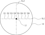
- FIG. 1 is a top view of an example of the optically absorptive anisotropic film of the present invention.
- FIG. 2 is a cross-sectional view taken along line AA in FIG.
- FIG. 3 is a diagram for explaining the measurement positions of the film thickness of the optically anisotropic film.
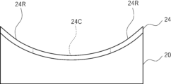
- FIG. 4 is a diagram for explaining the procedure for forming a film using a mold having a concave forming surface.
- FIG. 5 is a diagram for explaining the procedure for forming a film using a mold having a concave forming surface.
- FIG. 6 is a top view of the film used for molding.
- FIG. 7 is a diagram for explaining the procedure for forming a film using a mold having a convex forming surface.
- FIG. 8 is a diagram for explaining the procedure for forming a film using a mold having a convex forming surface.
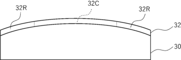
- FIG. 9 is a diagram for explaining the method 1.
- FIG. FIG. 10 is a diagram for explaining the method 1.
- FIG. FIG. 11 is a diagram for explaining the method 1.
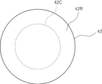
- FIG. FIG. 12 is a diagram for explaining the method 2.
- FIG. FIG. 13 is a top view of a planar optically absorbing anisotropic film used in method 2.
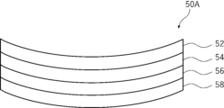
- FIG. 14 is a cross-sectional view showing an example of the laminate of the present invention.
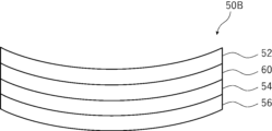
- FIG. 15 is a cross-sectional view showing another example of the laminate of the present invention.
- FIG. 16 is a cross-sectional view showing an example of the compound lens of the present invention.
- FIG. 17 is a diagram showing an example of a virtual reality display device of the present invention, illustrating an example of a light ray of a main image.
- absorption axis refers to the polarization direction in which the absorbance is maximum in the plane when linearly polarized light is incident.
- reflection axis refers to the polarization direction in which the reflectance is maximum in the plane when linearly polarized light is incident.
- transmission axis refers to the direction perpendicular to the absorption axis or reflection axis in the plane.
- slow axis refers to the direction in which the refractive index is maximum in the plane.
- Re( ⁇ ) and Rth( ⁇ ) respectively represent the in-plane retardation and the thickness retardation at a wavelength ⁇ .
- the wavelength ⁇ is 550 nm.
- Re( ⁇ ) and Rth( ⁇ ) are values measured at a wavelength ⁇ using an AxoScan (manufactured by Axometrics).
- AxoScan manufactured by Axometrics.
- Re( ⁇ ) R0( ⁇ )
- NAR-4T Abbe refractometer
- the measurement can be performed using a multi-wavelength Abbe refractometer DR-M2 (manufactured by Atago Co., Ltd.) in combination with an interference filter.
- values in the Polymer Handbook JOHN WILEY & SONS, INC.
- catalogs of various optical films can be used.
- Examples of average refractive index values of major optical films are as follows: cellulose acylate (1.48), cycloolefin polymer (1.52), polycarbonate (1.59), polymethyl methacrylate (1.49), and polystyrene (1.59).
- the A plate and the C plate are defined as follows. There are two types of A plates, positive A plates and negative A plates, and when the refractive index in the slow axis direction (the direction in which the refractive index in the plane is maximum) in the film plane is nx, the refractive index in the direction perpendicular to the slow axis in the plane is ny, and the refractive index in the thickness direction is nz, the positive A plate satisfies the relationship of formula (A1), and the negative A plate satisfies the relationship of formula (A2). Note that the positive A plate has a positive Rth value, and the negative A plate has a negative Rth value.
- Formula (A1) nx>ny ⁇ nz
- Formula (A2) ny ⁇ nx ⁇ nz
- ⁇ includes not only the case where the two are completely identical, but also the case where the two are substantially identical.
- “ny ⁇ nz” includes the case where (ny-nz) ⁇ d (where d is the thickness of the film) is -10 to 10 nm, preferably -5 to 5 nm
- "nx ⁇ nz” includes the case where (nx-nz) ⁇ d is -10 to 10 nm, preferably -5 to 5 nm.
- C plates There are two types of C plates: a positive C plate and a negative C plate.
- the positive C plate satisfies the relationship of formula (C1), and the negative C plate satisfies the relationship of formula (C2).
- the positive C plate has a negative Rth value, and the negative C plate has a positive Rth value.
- Formula (C2) nz ⁇ nx ⁇ ny The above “ ⁇ ” includes not only the case where the two are completely identical, but also the case where the two are substantially identical. For example, “substantially the same” includes the case where (nx-ny) x d (where d is the thickness of the film) is 0 to 10 nm, preferably 0 to 5 nm, in "nx ⁇ ny".
- a feature of the optically absorptive anisotropic film of the present invention is that the in-plane variation in film thickness in the non-flat portion is small.
- the present inventors have studied the cause of ghost generation when the laminated optical film described in Patent Document 1 is curved and applied to a pancake lens type virtual reality display device, and have found that the ghost generation occurs due to in-plane variation in film thickness in a linear polarizer molded into a curved shape. More specifically, when a linear polarizer is molded into a curved shape, there are parts that are easily stretched during molding and parts that are not easily stretched, and therefore the molded body has in-plane variation in thickness, and the ghost generation occurs due to the in-plane variation. Based on the above findings, the present inventors have found that the above problem can be solved by using a light absorption anisotropic film with small in-plane variation in a non-flat shape part (e.g., a curved shape part).
- a non-flat shape part e.g.,
- the optically absorptive anisotropic film of the present invention is a film having anisotropy of absorption, and preferably has anisotropy of absorption in an in-plane direction of the optically absorptive anisotropic film.
- the optically absorptive anisotropic film preferably functions as an absorptive linear polarizer.
- the optically absorptive anisotropic film of the present invention has a non-planar portion.
- the optically absorptive anisotropic film may be a non-planar portion throughout the film, or a portion of the film may be a non-planar portion.
- the other portion may be a planar portion.
- the non-planar portion means a portion having a non-planar shape.
- the non-planar shape means a shape other than a planar shape, for example a curved shape, that is, the non-planar shape portion may be a curved shape portion.
- the above-mentioned curved shape means a shape having a curvature exceeding 0, and includes a developable curved shape and a three-dimensional curved shape.
- a developable surface is a surface that can be developed into a plane without any part of the surface expanding or contracting.
- Examples of the curved shape that is a developable surface include surfaces that correspond to the peripheral surface of a cylinder, an elliptical cylinder, a cone, and an elliptical cone, and may be a convex curved surface or a concave curved surface.
- a three-dimensional curved surface means a curved surface that is not established by deformation of a plane, that is, a curved surface that is not a developable surface, and examples of the three-dimensional curved surface include surfaces that correspond to a spherical surface and a spheroidal surface, and surfaces that correspond to a curved surface whose cross section is a parabola or hyperbola (for example, a paraboloid of revolution), and may be a convex curved surface or a concave curved surface.
- the curved surface shape is preferably lenticular.
- lenticular curved surfaces include spherical and ellipsoidal shapes, and may be either convex or concave lenticular.
- the non-planar shaped portion of the optically absorbing anisotropic film is preferably spherical, spheroidal, or paraboloidal.
- the non-planar shaped portion is a curved shaped portion, and the curved shaped portion is a spherical shaped portion, spheroidal shaped portion, or paraboloidal shaped portion.
- FIG. 1 shows an example of the optically absorptive anisotropic film of the present invention.
- Fig. 1 is a top view of the optically absorptive anisotropic film
- Fig. 2 is a cross-sectional view taken along line AA in Fig. 1.
- Line AA is a line passing through center 12 of optically absorptive anisotropic film 10, which is circular when viewed in plan.
- the optically absorptive anisotropic film 10 has a curved shape. More specifically, as shown in Figure 2, the optically absorptive anisotropic film 10 has a shape that is curved in a convex shape toward the upper side of the paper (convex shape).
- the optically absorptive anisotropic film 10 has a convex shape that protrudes on one surface side. It can also be said that the optically absorptive anisotropic film 10 has a concave shape with the other surface side recessed. In the optically absorptive anisotropic film 10, the entire optically absorptive anisotropic film 10 corresponds to the non-planar portion. As shown in FIG. 2, the optically absorptive anisotropic film 10 has two opposing surfaces, a first surface 14 and a second surface 16.
- the first surface 14 is a curved surface that is convex toward the upper side of the paper
- the second surface 16 is a curved surface that is convex toward the upper side of the paper.
- the curved surface of the optically absorptive anisotropic film 10 shown in FIGS. 1 and 2 is a paraboloid of revolution, it may be a spherical or ellipsoidal shape.
- the shape of the optically absorptive anisotropic film 10 is circular.
- the center 12 of the optically absorptive anisotropic film 10 is the intersection point between the axis of the spheroid shape and the optically absorptive anisotropic film 10, and corresponds to the position where the optically absorptive anisotropic film 10 intersects with the normal to the center of the exit surface of the image display panel when the optically absorptive anisotropic film 10 is incorporated into the virtual reality display device described below.
- the optically absorptive anisotropic film 10 is disposed so as to be convex on the image display panel side.
- the outer contour line of the optically absorptive anisotropic film 10 (the contour line corresponding to the first surface 14 of the optically absorptive anisotropic film 10) is a parabola.
- the outer contour line of the optically absorptive anisotropic film 10 (the contour line corresponding to the first surface 14 of the optically absorptive anisotropic film 10) is circular.
- the diameter of the circle formed by the outer contour of the optically absorptive anisotropic film 10 when the optically absorptive anisotropic film 10 is cut along a plane parallel to the tangent plane to the center 12 of the optically absorptive anisotropic film 10 gradually increases.
- the non-planar portion of the optically absorptive anisotropic film is described as having a circular shape when viewed in a plane, but the present invention is not limited to this, and the non-planar portion of the optically absorptive anisotropic film may have an elliptical shape or another shape when viewed in a plane.
- the in-plane variation in the film thickness of the non-flat portion of the optically absorptive anisotropic film of the present invention is less than 10%. In particular, it is preferably 6% or less, more preferably 3% or less, in that the occurrence of ghosts is more suppressed when the film is applied to a pancake lens type virtual reality display device (hereinafter, simply referred to as "the advantage of the present invention being superior").
- the lower limit is not particularly limited, and may be 0%, and is often 0.1% or more.
- the in-plane variation in film thickness of the non-flat portion of the optically absorptive anisotropic film can be measured by the following method.
- the optically absorptive anisotropic film is cut with a microtome to expose a cross section, and the cross section is observed at an appropriate magnification (20,000 to 50,000 times) with a scanning electron microscope (SEM) to determine the film thickness of the non-planar portion of the optically absorptive anisotropic film.
- SEM scanning electron microscope
- the measurement sample may be subjected to appropriate treatment such as carbon deposition, etching, etc.
- the accelerating voltage is preferably optimized within the range of 1 to 10 kV.
- the laminate when the optically absorptive anisotropic film constitutes a laminate together with other layers, the laminate may be cut with a microtome to expose a cross section, and the film thickness of the optically absorptive anisotropic film may be determined by the above procedure.
- the measurement object when the measurement object is a laminate including the optically absorptive anisotropic film and other layers, the other layers may be peeled off and the measurement may be performed.
- the position at which the film thickness of the non-flat portion of the optically absorptive anisotropic film is measured is determined by the following method:
- the optically absorptive anisotropic film 10 shown in Figures 1 and 2 will be described as an example.
- the optically absorptive anisotropic film is viewed in plan from the normal direction of the emission surface of the image display panel, and the intersection point of the optically absorptive anisotropic film viewed in plan with an axis extending in the normal direction through the center of the emission surface is defined as the center of the non-planar portion.
- center 12 of optically absorptive anisotropic film 10 corresponds to the center of the non-planar portion.
- a straight line passing through the center and extending in one in-plane direction is defined as a first straight line
- a straight line extending in the in-plane direction perpendicular to the first straight line is defined as a second straight line.
- a straight line passing through the center 12 and extending in the left-right direction of the paper is defined as a first straight line SL1
- a straight line extending perpendicular to the straight line SL1 is defined as a second straight line SL2.
- the line extending in the left-right direction of the paper and the line extending in the up-down direction are defined as the first straight line and the second straight line, but this is not limited to the embodiment, and any straight line extending in one in-plane direction may be adopted as the first straight line.
- the first straight line and the second straight line located in the region of the non-flat shape part (within the region of the projected image) in plan view are each divided into 10 parts. As shown in FIG.
- the first straight line SL1 and the second straight line SL2 shown by dashed lines are divided into 10 parts of equal length.
- 8 division lines excluding the division lines located at both ends are selected, and the film thickness at the position of the optically anisotropic film corresponding to any position on each division line is obtained from the above-mentioned SEM observation diagram.
- the first straight line SL1 is divided into 10 parts to obtain 8 division lines (D1 to D8) excluding the division lines located at both ends, and the position of any one point on each division line is selected, and the film thickness at the position of the optically anisotropic film corresponding to that position is calculated.
- the position of the optically anisotropic film corresponding to any position on the division line corresponds to the intersection point between the optically anisotropic film and an axis extending in the normal direction of the projection image on which the division line is drawn, passing through the selected position on the division line drawn in the projection image obtained by viewing the optically anisotropic film in plan view.
- the position on the division line in the projected image is reflected in the position of the optically anisotropic film, and the film thickness at that position of the optically anisotropic film (the film thickness in the normal direction of the tangent plane at that position) is calculated. According to the above procedure, the film thicknesses of the eight optically anisotropic films can be calculated.
- the film thicknesses of the eight optically anisotropic films can be calculated according to the same procedure as above.
- the film thickness values at the 16 locations thus obtained are used to calculate the average value of these values, the maximum value among these values, and the minimum value among these values.
- the larger difference hereinafter also referred to as the "specific difference" between the difference between the maximum value and the average value and the difference between the minimum value and the average value is selected, and the ratio of the obtained difference to the average value [(specific difference/average value) x 100] is calculated.
- the radius of curvature of the curved portion of the optically absorptive anisotropic film is not particularly limited, but from the viewpoint of better effects of the present invention, it is preferably 20 to 80 mm, more preferably 30 to 80 mm, and even more preferably 35 to 60 mm.
- the radius of curvature of the curved portion of the optically absorptive anisotropic film may be constant or may vary at any position on the curved portion, and it is preferable that the radius of curvature at any position is within the above range.
- the shape of the curved portion corresponds to a spherical shape.
- the minimum radius of curvature of the curved surface of the optically absorptive anisotropic film is not particularly limited, but in terms of obtaining a better effect of the present invention, it is preferably 30 to 80 mm, and more preferably 35 to 60 mm.
- the maximum radius of curvature of the curved surface of the optically absorptive anisotropic film is not particularly limited, but in terms of superior effects of the present invention, it is preferably 35 to 80 mm, and more preferably 35 to 60 mm.
- the size of the non-planar portion when viewed in plan from the rotation axis direction of these shapes is not particularly limited, and the circle equivalent diameter of the non-planar portion is preferably 30 to 80 mm, and more preferably 40 to 60 mm.
- the equivalent circle diameter is the diameter of a perfect circle having the same projected area as the projected area of the non-flat portion during observation.
- the film thickness of the non-flat portion of the optically absorptive anisotropic film is not particularly limited, but in terms of superior effects of the present invention, it is preferably 8.0 ⁇ m or less, more preferably 0.5 to 5.0 ⁇ m, and even more preferably 1.0 to 3.0 ⁇ m.
- the above-mentioned film thickness means an average film thickness value obtained when calculating the above-mentioned in-plane variation in film thickness of the non-flat portion.
- the optically absorptive anisotropic film contains a dichroic substance, and more preferably contains a dichroic substance and a liquid crystal compound.
- the materials contained in the optically absorptive anisotropic film will be described in detail below.
- the dichroic substance means a substance whose absorbance varies depending on the direction. In the light absorption anisotropic film, the dichroic substance may be fixed. It should be noted that a dichroic substance is a substance that exhibits dichroism, and dichroism refers to a property in which the absorbance differs depending on the direction of polarization.
- the dichroic material is not particularly limited, and examples include visible light absorbing materials (dichroic dyes), luminescent materials (fluorescent materials, phosphorescent materials), ultraviolet absorbing materials, infrared absorbing materials, nonlinear optical materials, carbon nanotubes, and inorganic materials (e.g., quantum rods), and any conventionally known dichroic material (preferably a dichroic dye) can be used.
- the dichroic substance is preferably iodine or a dichroic azo dye compound.
- the dichroic azo dye compound means an azo dye compound whose absorbance varies depending on the direction.
- the dichroic azo dye compound may or may not exhibit liquid crystallinity. When the dichroic azo dye compound exhibits liquid crystallinity, it may exhibit either nematic or smectic properties.
- the temperature range in which the liquid crystal phase is exhibited is preferably room temperature (about 20 to 28°C) to 300°C, and more preferably 50 to 200°C from the viewpoints of handling and manufacturing suitability.
- first dichroic azo dye compound at least one dye compound having a maximum absorption wavelength in the wavelength range of 560 to 700 nm
- second dichroic azo dye compound at least one dye compound having a maximum absorption wavelength in the wavelength range of 455 nm or more and less than 560 nm
- three or more dichroic azo dye compounds may be used in combination.
- a first dichroic azo dye compound in order to make the light absorption anisotropic film closer to black, it is preferable to use a first dichroic azo dye compound, a second dichroic azo dye compound, and at least one dye compound having a maximum absorption wavelength in the wavelength range of 380 nm or more and less than 455 nm in combination.
- Dichroic substances that can be used in the present invention include those described in WO 2018/186503, WO 2019/189345, and WO 2018/124198.
- the content of the dichroic substance is preferably 1 to 30 mass %, more preferably 5 to 25 mass %, and even more preferably 10 to 20 mass %, based on the total solid mass of the light absorbing anisotropic film.
- the optically absorptive anisotropic film preferably contains a liquid crystal compound.
- a liquid crystal compound either a polymer liquid crystal compound or a low molecular weight liquid crystal compound can be used, and the polymer liquid crystal compound is preferred because it can increase the degree of orientation.
- a polymer liquid crystal compound and a low molecular weight liquid crystal compound may be used in combination.
- the liquid crystal compound may be fixed in the light absorption anisotropic film.
- polymeric liquid crystal compound refers to a liquid crystal compound having a repeating unit in the chemical structure.
- the term “low molecular weight liquid crystal compound” refers to a liquid crystal compound that does not have a repeating unit in its chemical structure.
- low molecular weight liquid crystal compound examples include compounds that exhibit a nematic liquid crystal phase and compounds that exhibit a smectic liquid crystal phase, and in terms of increasing the degree of orientation, compounds that exhibit a smectic liquid crystal phase are preferred.
- the liquid crystal compounds described in JP 2013-228706 A can be mentioned.
- the polymer liquid crystal compound examples include the thermotropic liquid crystal polymers described in JP-A-2011-237513.
- the polymer liquid crystal compound preferably forms a nematic liquid crystal phase.
- the temperature range in which the polymer liquid crystal compound exhibits the nematic liquid crystal phase is preferably from room temperature (23° C.) to 450° C., and from the viewpoints of handling and manufacturing suitability, preferably from 50 to 400° C.
- the content of the liquid crystal compound in the light absorption anisotropic film is preferably 25 to 2000 parts by mass, more preferably 100 to 1300 parts by mass, and even more preferably 200 to 900 parts by mass, relative to 100 parts by mass of the dichroic substance.
- the liquid crystal compound may be contained alone or in combination of two or more. When two or more liquid crystal compounds are contained, the content of the liquid crystal compounds means the total content of the liquid crystal compounds.
- the aligned liquid crystal compound is fixed, and in particular, it is more preferable that the homogeneously aligned liquid crystal compound is fixed in the optically absorptive anisotropic film.
- the dichroic substance is preferably aligned in a specific direction.
- the dichroic substance is more preferably aligned in one direction in the plane.
- the dichroic substance is aligned in the homogeneously aligned liquid crystal compound.
- the optically absorptive anisotropic film is preferably a film formed using a composition for forming an optically absorptive anisotropic film that contains a liquid crystal compound and a dichroic substance.
- the optically absorptive anisotropic film may contain a resin, and in particular, the optically absorptive anisotropic film may contain a dichroic material and a resin.
- the type of resin is not particularly limited, but polyvinyl alcohol-based resins (hereinafter also referred to as "PVA-based resins") are preferred.
- PVA-based resins polyvinyl alcohol-based resins
- the single plate transmittance of the optically absorptive anisotropic film is preferably 40% or more, more preferably 42% or more. There is no particular upper limit, but it is often 60% or less.
- the polarization degree of the light absorption anisotropic film is preferably 90% or more, more preferably 95% or more, and even more preferably 99% or more. There is no particular upper limit, but it is often less than 100%.
- the single plate transmittance and the degree of polarization are measured using an automatic polarizing film measuring device: VAP-7070 (manufactured by JASCO Corporation).
- the optically absorptive anisotropic film may contain, in addition to the above-mentioned components, an adhesion improver, a plasticizer, a polymer, and the like.
- adhesion improver include the reactive additives listed in paragraphs [0123] to [0129] of JP 2019-91088 A, and the boronic acid monomers listed in paragraphs [0015] to [0028] of WO 2015/053359 A.
- the optically absorptive anisotropic film of the present invention may contain an interfacial improving agent.
- the interfacial improver is not particularly limited, and a polymer-based interfacial improver and a low molecular weight interfacial improver can be used, and the compounds described in paragraphs [0253] to [0293] of JP2011-237513A can be used.
- As the interface improver a silicon-based polymer can be used.
- fluorine (meth)acrylate polymers described in paragraphs [0018] to [0043] of JP-A-2007-272185 and the like can also be used.
- Examples of the interface improver include compounds described in paragraphs [0079] to [0102] of JP-A-2007-069471, polymerizable liquid crystal compounds represented by formula (4) described in JP-A-2013-047204 (particularly compounds described in paragraphs [0020] to [0032]), polymerizable liquid crystal compounds represented by formula (4) described in JP-A-2012-211306 (particularly compounds described in paragraphs [0022] to [0029]), and liquid crystal alignment promoters represented by formula (4) described in JP-A-2002-129162 (particularly compounds described in paragraphs [0032] to [0040]).
- the content of the interfacial improver is preferably 0.005 to 15 mass %, more preferably 0.01 to 5 mass %, and even more preferably 0.015 to 3 mass %, relative to the total mass of the optically absorptive anisotropic film.
- the total amount of the multiple interfacial improvers is within the above-mentioned range.
- the method for producing the optically absorptive anisotropic film of the present invention is not particularly limited as long as it can produce an optically absorptive anisotropic film having the above-mentioned properties.
- a method may be mentioned in which a planar optically absorptive anisotropic film is produced, and then the planar optically absorptive anisotropic film is molded to produce an optically absorptive anisotropic film having a non-planar portion.
- Methods for molding a planar optically absorptive anisotropic film include, for example, a method using a mold having a convex molding surface and a mold having a concave molding surface (Method 1), and a method for molding the planar optically absorptive anisotropic film by heating the film with a distribution of heating temperature in the in-plane direction during molding (Method 2).
- Methods 1 and 2 will be described in detail.
- the procedure for obtaining the optically absorptive anisotropic film 10 shown in Figs. 1 and 2 will be described in detail as an example.
- the method for producing the planar optically absorptive anisotropic film is not particularly limited, and may be any known method. Among them, the method for producing the planar optically absorptive anisotropic film using a composition for forming an optically absorptive anisotropic film containing a dichroic substance and a liquid crystal compound is preferred.
- a method including, in this order, a step of applying a composition for forming an optically absorptive anisotropic film onto a flat substrate to form a coating film (hereinafter also referred to as a “coating film forming step"), and a step of orienting a liquid crystalline component or a dichroic substance contained in the coating film (hereinafter also referred to as an "orientation step").
- the liquid crystal component is a component including not only the above-mentioned liquid crystal compound but also a dichroic substance having liquid crystallinity when the above-mentioned dichroic substance has liquid crystallinity.
- the coating film forming step is a step of forming a coating film by applying a composition for forming an optically absorptive anisotropic film onto a flat substrate.
- the composition for forming an optically absorptive anisotropic film includes the above-mentioned dichroic substance and liquid crystal compound.
- the dichroic substance and liquid crystal compound contained in the composition for forming an optically absorptive anisotropic film may have a polymerizable group.
- the polymerizable group is preferably an acryloyl group, a methacryloyl group, an epoxy group, an oxetanyl group, or a styryl group, and more preferably an acryloyl group or a methacryloyl group.
- the dichroic substance and the liquid crystal compound have a polymerizable group, these compounds can be fixed in the optically absorptive anisotropic film in the curing step described below.
- the substrate used in this step is not particularly limited, and any known planar substrate can be used.
- an alignment film may be provided on the substrate. By providing the alignment film, the liquid crystal component can be aligned.
- the alignment film may be a photo-alignment film.
- the composition for forming an optically absorbing anisotropic film can be easily applied by using a composition for forming an optically absorbing anisotropic film that contains a solvent, or by using a composition for forming an optically absorbing anisotropic film that has been made into a liquid such as a molten liquid by heating or the like.
- methods for applying the composition for forming an optically absorptive anisotropic film include known methods such as roll coating, gravure printing, spin coating, wire bar coating, extrusion coating, direct gravure coating, reverse gravure coating, die coating, spraying, and inkjet printing.
- the alignment step is a step for aligning the liquid crystal component contained in the coating film, thereby obtaining a planar optically absorptive anisotropic film.
- the orientation step may include a drying treatment. By the drying treatment, components such as a solvent can be removed from the coating film. The drying treatment may be performed by leaving the coating film at room temperature for a predetermined time (for example, natural drying), or may be performed by heating and/or blowing air.
- the liquid crystal component contained in the composition for forming an optically absorptive anisotropic film may be aligned by the above-mentioned coating film forming step or drying treatment.
- the coating film is dried to remove the solvent from the coating film, thereby obtaining a coating film having optical absorption anisotropy.
- the drying treatment is carried out at a temperature equal to or higher than the temperature at which the liquid crystal component contained in the coating film transitions from the liquid crystal phase to the isotropic phase, the heating treatment described below does not need to be carried out.
- the transition temperature from the liquid crystal phase to the isotropic phase of the liquid crystal component contained in the coating film is preferably 10 to 250°C, more preferably 25 to 190°C, from the standpoint of manufacturability and other factors.
- a transition temperature of 10°C or higher is preferable because no cooling process is required to lower the temperature to the temperature range in which the liquid crystal phase is exhibited.
- a transition temperature of 250°C or lower is preferable because high temperatures are not required even when heating until the isotropic phase is achieved in order to suppress alignment defects, and this reduces waste of thermal energy as well as deformation and deterioration of the substrate.
- the alignment step preferably includes a heat treatment, which allows the liquid crystal component contained in the coating film to be aligned, so that the coating film after the heat treatment can be suitably used as an optically absorptive anisotropic film.
- the heat treatment is preferably performed at 10 to 250° C., more preferably at 25 to 190° C.
- the heating time is preferably 1 to 300 seconds, more preferably 1 to 60 seconds.
- the orientation process may include a cooling process carried out after the heating process.
- the cooling process is a process in which the coated film after heating is cooled to about room temperature (20 to 25°C). This makes it possible to fix the orientation of the liquid crystal component contained in the coated film.
- the method for forming a planar optically absorptive anisotropic film may include a step of curing the optically absorptive anisotropic film (hereinafter also referred to as a "curing step") after the above-mentioned alignment step.
- the curing step is carried out by heating and/or light irradiation (exposure) when the compound contained in the optically absorptive anisotropic film has a polymerizable group.
- the curing step is preferably carried out by light irradiation from the viewpoint of productivity.
- the light source used for curing can be various light sources such as infrared light, visible light, and ultraviolet light, but ultraviolet light is preferable.
- ultraviolet light may be irradiated while heating during curing, or ultraviolet light may be irradiated through a filter that transmits only specific wavelengths.
- the heating temperature during exposure is preferably 25 to 140° C., although it depends on the transition temperature of the liquid crystal component contained in the liquid crystal film.
- the exposure may be carried out under a nitrogen atmosphere.
- the curing of the liquid crystal film proceeds by radical polymerization, it is preferable to carry out the exposure under a nitrogen atmosphere, since this reduces the inhibition of polymerization caused by oxygen.
- a method for producing a planar optically absorptive anisotropic film using a composition for forming an optically absorptive anisotropic film containing a dichroic substance and a liquid crystal compound has been described, but the present invention is not limited to this embodiment.
- a method for producing a planar optically absorptive anisotropic film containing iodine and a PVA-based resin includes subjecting a PVA-based resin film to a dyeing treatment with iodine and a stretching treatment (typically, uniaxial stretching). The dyeing with iodine is carried out, for example, by immersing the PVA-based resin film in an aqueous iodine solution.
- the stretching ratio of the uniaxial stretching is preferably 3 to 7 times.
- the stretching may be carried out after the dyeing treatment or while dyeing.
- the film may be stretched and then dyed.
- the PVA-based resin film may be subjected to a swelling treatment, a crosslinking treatment, a washing treatment, a drying treatment, or the like. For example, by immersing the PVA-based resin film in water and washing it with water before dyeing, it is possible to wash off dirt and antiblocking agents on the surface of the PVA-based resin film, and also to swell the PVA-based resin film and prevent uneven dyeing.
- Another embodiment of the method for producing a planar light-absorbing anisotropic film containing iodine and a PVA-based resin includes a light-absorbing anisotropic film obtained by using a laminate of a resin substrate and a PVA-based resin layer (PVA-based resin film) laminated on the resin substrate, or a laminate of a resin substrate and a PVA-based resin layer coated on the resin substrate.
- the light-absorbing anisotropic film obtained by using a laminate of a resin substrate and a PVA-based resin layer coated on the resin substrate can be produced by, for example, applying a PVA-based resin solution to a resin substrate, drying the resin substrate to form a PVA-based resin layer on the resin substrate, and obtaining a laminate of the resin substrate and the PVA-based resin layer; stretching and dyeing the laminate to make the PVA-based resin layer into a light-absorbing anisotropic film.
- the details of stretching, dyeing, swelling treatment, crosslinking treatment, washing treatment, and drying treatment are the
- Method 1 is a method using a mold having a convex molding surface and a mold having a concave molding surface.
- Figures 4 and 5 show the procedure for molding a film using a mold having a concave molding surface
- Figure 6 shows the film used for molding.
- a circular film 22 is placed on a mold 20 having a concave molding surface, and as shown in Figure 5, the film 22 is deformed so as to fit the molding surface of the mold 20, thereby obtaining a film 24 with the concave shape transferred thereto.
- Figures 7 and 8 show the procedure for molding a film using a mold having a convex molding surface
- Figure 6 shows the film used for molding.
- a circular film 22 is placed on a mold 26 having a convex-shaped molding surface, and as shown in Figure 8, the film 22 is deformed so as to fit the molding surface of the mold 26, thereby obtaining a film 28 to which the convex shape has been transferred.
- a difference in the stretching ratio occurs between the central portion 22C and the peripheral portion 22R of the film 22 as shown in Figures 6 and 7.
- the peripheral portion 22R of the film 22 is more easily stretched than the central portion 22C of the film 22.
- the film thickness of the peripheral portion 28R is thinner than the film thickness of the central portion 28C.
- Step 1A in which a mold having a convex molding surface is used to deform a planar optically absorptive anisotropic film along the molding surface of the mold; and Step 2A, in which a mold having a concave molding surface with a radius of curvature smaller than the radius of curvature of the convex molding surface is used to deform the optically absorptive anisotropic film to which the convex shape has been transferred obtained in Step 1A, along the concave molding surface, with the surface of the optically absorptive anisotropic film to which the convex shape has been transferred being brought into contact with the mold in Step 1A being brought into contact
- a production method comprising: Step 1B, using a mold having a concave molding surface, deforming a planar optically absorptive anisotropic film along the molding surface of the mold; and Step 2B, using the other side of the mold having a convex molding surface with a smaller radius of curvature than the radius of curvature of the concave molding surface, bringing the surface of the optically absorptive anisotropic film to which the concave shape obtained in Step 1B has been transferred, opposite to the surface that was in contact with the mold in Step 1B, into the molding surface side of the mold, and deforming the optically absorptive anisotropic film to which the concave shape has been transferred, along the convex molding surface of the mold.
- Method 1 The first embodiment of Method 1 will be representatively described below with reference to the drawings.
- a mold having a convex molding surface is used, and step 1A is carried out in which a planar optically absorptive anisotropic film is deformed along the molding surface of the mold.
- step 1A By carrying out this step, an optically absorptive anisotropic film 32 with a convex shape transferred onto a mold 30 having a convex molding surface is obtained, as shown in Fig. 9.
- the film thickness of the peripheral portion 32R of the optically absorptive anisotropic film 32 is thinner than the film thickness of the central portion 32C, as described above with reference to Figs.
- a mold having a concave molding surface with a radius of curvature smaller than the radius of curvature of the convex molding surface is used to deform the optically absorptive anisotropic film with the convex shape transferred thereto obtained in step 1A along the concave molding surface, with the surface of the optically absorptive anisotropic film with the convex shape transferred thereto being the molding surface side of the mold.
- the radius of curvature of the molding surface of the mold 34 with the concave molding surface used in step 2A is smaller than the radius of curvature of the molding surface of the mold 30 with the convex molding surface used in step 1A.
- the optically absorptive anisotropic film 32 obtained in step 1A is placed on the mold 34 with a molding surface with a radius of curvature smaller than that of the mold 30 used in step 1A.
- the optically absorptive anisotropic film 32 is placed on the mold 34, the surface of the optically absorptive anisotropic film 32 opposite to the surface that was in contact with the mold 30 faces the molding surface of the mold 34.
- the optically absorptive anisotropic film 32 is deformed so as to fit the molding surface of the mold 34, to obtain an optically absorptive anisotropic film 36 having a curved shaped portion.
- step 2A the reduction in thickness of central part 32C of optically absorptive anisotropic film 32 is larger than the reduction in thickness of peripheral part 32R.
- step 1A the reduction in film thickness at the peripheral portion of the optically absorptive anisotropic film is greater than the reduction in film thickness at the central portion
- step 2A the reduction in film thickness at the central portion of the optically absorptive anisotropic film is greater than the reduction in film thickness at the peripheral portion.
- steps 1A and 2A are performed, the reduction in film thickness at the central portion and the peripheral portion are approximately the same, and as a result, the occurrence of in-plane variations in film thickness in the obtained optically absorptive anisotropic film 36 is suppressed.
- step 1B the decrease in film thickness at the center of the optically absorptive anisotropic film is greater than the decrease in film thickness at the periphery
- step 2B the decrease in film thickness at the periphery of the optically absorptive anisotropic film is greater than the decrease in film thickness at the center.
- the optically absorbing anisotropic film when the optically absorbing anisotropic film is deformed along the molding surface of the mold, the optically absorbing anisotropic film may be heated as necessary.
- the heating temperature during the heat treatment is appropriately selected according to the material and film thickness of the optically absorbing anisotropic film used.
- the heating temperature is preferably equal to or higher than the glass transition temperature of the optically absorbing anisotropic film.
- the upper limit of the heating temperature is not particularly limited, but it is preferably within (the glass transition temperature of the optically absorbing anisotropic film + 100 ° C.).
- the optically absorptive anisotropic film itself is applied to steps 1A, 2A, 1B, and 2B, but a laminate described below may be applied to steps 1A, 2A, 1B, and 2B.
- a support is included in the laminate, it is preferable to heat the laminate to a temperature equal to or higher than the glass transition temperature of the support during the heat treatment.
- the method of deforming the optically absorptive anisotropic film along the molding surface of the mold is not particularly limited, but examples include a method of deforming the optically absorptive anisotropic film by drawing a vacuum, and a method of deforming the optically absorptive anisotropic film by applying pressure.
- the radius of curvature of the molding surface of the mold used in step 2A is smaller than the radius of curvature of the molding surface of the mold used in step 1A.
- the ratio (CA2/CA1) of the radius of curvature (CA2) of the molding surface of the mold used in step 2A to the radius of curvature (CA1) of the molding surface of the mold used in step 1A is selected from the optimum values according to the optically absorptive anisotropic film to be produced, and is preferably 0.6 to 0.9, and more preferably 0.7 to 0.85.
- the smallest radius of curvature is regarded as the above-mentioned "radius of curvature of the molding surface of the mold used in step 1A.” Furthermore, in cases where the radius of curvature varies depending on the position on the molding surface of the mold used in step 2A, the smallest radius of curvature is defined as the "radius of curvature of the molding surface of the mold used in step 2A.”
- the radius of curvature of the molding surface of the mold used in step 2B is smaller than the radius of curvature of the molding surface of the mold used in step 1B.
- the ratio (CB2/CB1) of the radius of curvature (CB2) of the molding surface of the mold used in step 2B to the radius of curvature (CB1) of the molding surface of the mold used in step 1B is selected from the optimum values according to the optically absorptive anisotropic film to be produced, and is preferably 0.6 to 0.9, and more preferably 0.7 to 0.85.
- the smallest radius of curvature is regarded as the "radius of curvature of the molding surface of the mold used in step 1B.” Furthermore, in cases where the radius of curvature varies depending on the position of the molding surface of the mold used in step 2B, the smallest radius of curvature is regarded as the "radius of curvature of the molding surface of the mold used in step 2B.”
- Method 2 is a method in which a flat optically absorptive anisotropic film is heated and molded with a distribution of heating temperature in the in-plane direction during molding.
- a first embodiment of Method 2 is a production method including the steps of heating a planar optically absorptive anisotropic film so that the heating temperature of the peripheral portion surrounding the central portion of the planar optically absorptive anisotropic film is higher than the heating temperature of the central portion of the film, and then using a mold having a concave molding surface, deforming the heated planar optically absorptive anisotropic film along the molding surface.
- a second embodiment of Method 2 is a manufacturing method including a step of heating a planar optically absorptive anisotropic film so that the heating temperature of the peripheral portion surrounding the central portion of the planar optically absorptive anisotropic film is lower than the heating temperature of the central portion of the planar optically absorptive anisotropic film, and using a mold having a convex molding surface, deforming the heated planar optically absorptive anisotropic film along the molding surface.
- the first embodiment of Method 2 will be representatively described below with reference to the drawings.
- the thickness of the film at the center tends to be thinner than the thickness of the peripheral edge. Therefore, in the first embodiment of the method 2, as shown in Figs. 12 and 13, the heating temperature of the peripheral portion 42R of the planar optically absorptive anisotropic film 42 arranged on a mold 40 having a concave molding surface is made higher than the heating temperature of the central portion 42C, so that the peripheral portion 42R is easily stretched when the optically absorptive anisotropic film 42 is deformed along the molding surface.
- the reduction in film thickness at the central portion is usually greater than the reduction in film thickness at the peripheral portion, but by changing the heating conditions for the central portion and the peripheral portion, the central portion is made less likely to stretch and the peripheral portion is made more likely to stretch, suppressing the reduction in film thickness at the central portion while increasing the reduction in film thickness at the peripheral portion.
- the in-plane variation in film thickness is suppressed in the deformed optically absorptive anisotropic film.
- the reduction in film thickness at the periphery is usually greater than the reduction in film thickness at the center, by changing the heating conditions for the center and periphery, the reduction in film thickness at the periphery is suppressed while the reduction in film thickness at the center is increased. As a result, the in-plane variation in film thickness is suppressed in the deformed optically absorptive anisotropic film.
- the optimum heating conditions for the optically absorptive anisotropic film are appropriately selected depending on the type of material of the optically absorptive anisotropic film used and the shape of the non-flat portion.
- the heating temperature is preferably equal to or higher than the glass transition temperature of the optically absorptive anisotropic film.
- the upper limit of the heating temperature is not particularly limited, but is preferably within (the glass transition temperature of the optically absorptive anisotropic film + 100°C).
- a laminate described below may also be applied to method 2. In that case, when a support is included in the laminate, it is preferable to heat the laminate to a temperature equal to or higher than the glass transition temperature of the support during the heat treatment.
- the heating method in method 2 is not particularly limited, but examples include heating by contact with a heated solid, heating by contact with a heated liquid, heating by contact with a heated gas, heating by infrared radiation, and heating by microwave radiation. Of these, heating by infrared radiation, which allows heating remotely just before molding, is preferred.
- the wavelength of the infrared rays used for heating is preferably 1.0 to 30.0 ⁇ m, and more preferably 1.5 to 5 ⁇ m.
- IR (infrared) light sources include near-infrared lamp heaters in which a tungsten filament is enclosed in a quartz tube, and wavelength control heaters in which quartz tubes are multiplexed and a part between the quartz tubes is cooled with air.
- Methods for providing an intensity distribution of infrared irradiation include a method of varying the density of the IR light source arrangement, and a method of placing a filter with a patterned transmittance for infrared light between the IR light source and the planar light-absorbing anisotropic film.
- filters with a patterned transmittance include those in which metal is deposited on glass, those in which the reflection band of a cholesteric liquid crystal layer is made infrared, those in which the reflection band is made infrared with a dielectric multilayer film, and ink that absorbs infrared rays.
- the temperature control of the planar light-absorbing anisotropic film is controlled by the intensity of infrared irradiation, and is controlled by the infrared irradiation time and the illuminance of infrared irradiation.
- the temperature of the planar light-absorbing anisotropic film can be monitored using a non-contact radiation thermometer and a thermocouple, and it is possible to mold it at a target temperature.
- the laminate of the present invention includes the optically absorptive anisotropic film described above.
- the laminate of the present invention includes other components in addition to the above-mentioned light absorptive anisotropic film.
- the other components are not particularly limited, and examples thereof include a retardation layer, a cholesteric liquid crystal layer, a linear polarization type reflective polarizer, a surface antireflection layer, a pressure-sensitive adhesive layer, a support, an alignment film, and a protective layer.
- FIG. 14 shows an example of the laminate of the present invention.
- FIG. 14 includes, in this order, a light absorbing anisotropic film 52, a retardation layer 54 having a function of converting linearly polarized light into circularly polarized light, a positive C plate 56, and a cholesteric liquid crystal layer 58.
- FIG. 15 shows another example of the laminate of the present invention.
- the laminate 50B shown in FIG. 15 includes, in this order, an optically absorptive anisotropic film 52, a linear polarization type reflective polarizer 60, a retardation layer 54 having a function of converting linearly polarized light into circularly polarized light, and a positive C plate 56. As shown in FIGS.
- all of the members included in the laminate 50A and the laminate 50B have a curved surface shape similar to that of the optically absorptive anisotropic film 52.
- the angle between the slow axis of the retardation layer 54 and the transmission axis of the optically absorptive anisotropic film 52 is preferably within the range of 45° ⁇ 10°.
- the laminate 50A and the laminate 50B each include two retardation layers, that is, a retardation layer 54 and a positive C plate 56.
- a retardation layer having a function of converting linearly polarized light into circularly polarized light may be disposed on the side opposite to the retardation layer 54 of the optically absorptive anisotropic film 52 of the laminate 50A. Also, a retardation layer having a function of converting linearly polarized light into circularly polarized light may be disposed on the side opposite to the linear polarization type reflective polarizer 60 of the optically absorptive anisotropic film 52 of the laminate 50B.
- the laminates 50A and 50B are suitably applied to a virtual reality display device, which will be described later.
- the optically absorptive anisotropic film 52 is the optically absorptive anisotropic film described above.
- the optically absorptive anisotropic film 52 corresponds to the optically absorptive anisotropic film 10 shown in FIGS.
- the members other than the optically absorptive anisotropic film contained in the laminate will be described in detail.
- a retardation layer having a function of converting linearly polarized light into circularly polarized light (hereinafter, also simply referred to as a "specific retardation layer”) is one type of retardation layer.
- the specific retardation layer is not particularly limited as long as it has a function of converting linearly polarized light into circularly polarized light, and an example of the specific retardation layer is a ⁇ /4 plate.
- a ⁇ /4 plate is a plate having a ⁇ /4 function, specifically, a plate having the function of converting linearly polarized light of a certain wavelength (preferably visible light) into circularly polarized light (or circularly polarized light into linearly polarized light).
- the in-plane retardation of the ⁇ /4 plate at a wavelength of 550 nm is not particularly limited, but is preferably from 120 to 150 nm, more preferably from 125 to 145 nm, and even more preferably from 135 to 140 nm.
- a retardation layer having an in-plane retardation at a wavelength of 550 nm that is 3/4 or 5/4 of any wavelength of visible light is also preferable.
- the specific retardation layer may have reverse wavelength dispersion, which means that the retardation value at a wavelength increases as the wavelength increases.
- the specific retardation layer may have a multi-layer structure, and a specific example of such a structure is a broadband ⁇ /4 plate formed by laminating a ⁇ /4 plate and a ⁇ /2 plate.
- the angle between the slow axis of the specific retardation layer and the absorption axis of the light absorption anisotropic film is not particularly limited, but is preferably within the range of 45° ⁇ 10°.
- the specific retardation layer may be a layer formed by fixing liquid crystal compounds that are twisted and aligned with the thickness direction as the helical axis.
- a retardation layer having a layer formed by fixing rod-shaped liquid crystal compounds or discotic liquid crystal compounds that are twisted and aligned with the thickness direction as the helical axis.
- the thickness of the specific retardation layer is not particularly limited, but is preferably 0.1 to 8 ⁇ m, and more preferably 0.3 to 5 ⁇ m.
- the positive C plate is a type of retardation layer.
- the positive C plate is a retardation layer having substantially zero in-plane retardation and a negative retardation in the thickness direction, and functions as an optical compensation layer for increasing the degree of polarization of transmitted light with respect to obliquely incident light.
- the in-plane retardation of the positive C plate at a wavelength of 550 nm is preferably 10 nm or less.
- the retardation in the thickness direction of the positive C plate at a wavelength of 550 nm is preferably ⁇ 600 to ⁇ 40 nm.
- the material constituting the positive C plate is not particularly limited, but it is preferable that the plate be formed from a composition containing a liquid crystal compound.
- a positive C plate can be obtained by vertically aligning rod-shaped polymerizable liquid crystal compounds contained in a polymerizable liquid crystal composition and fixing the alignment state by polymerization.
- the plate can also be formed from a composition containing a side-chain polymer liquid crystal compound as the liquid crystal compound.
- the thickness of the positive C plate is not particularly limited, but from the viewpoint of thinness, 0.5 to 10 ⁇ m is preferable, and 0.5 to 5 ⁇ m is more preferable.
- the cholesteric liquid crystal layer is an optical member that separates incident light into right-handed circularly polarized light and left-handed circularly polarized light, specularly reflects one of the circularly polarized light, and transmits the other circularly polarized light.
- the cholesteric liquid crystal layer may be a cholesteric liquid crystal layer formed by fixing a cholesteric liquid crystal phase.
- the cholesteric liquid crystal layer is preferable as an optical film used for curved surface molding because it suppresses the decrease in polarization degree and the distortion of the polarization axis when it is stretched or molded into a three-dimensional shape. In addition, the decrease in polarization degree caused by the distortion of the polarization axis is unlikely to occur.
- the cholesteric liquid crystal layer preferably has at least a blue light reflecting layer having a reflectance of 40% or more at a wavelength of 460 nm, a green light reflecting layer having a reflectance of 40% or more at a wavelength of 550 nm, a yellow light reflecting layer having a reflectance of 40% or more at a wavelength of 600 nm, and a red light reflecting layer having a reflectance of 40% or more at a wavelength of 650 nm.
- This configuration is preferable because it can exhibit high reflection characteristics over a wide wavelength range in the visible range.
- the above reflectances are reflectances when non-polarized light is incident on the cholesteric liquid crystal layer at each wavelength.
- the cholesteric liquid crystal layer may have a pitch gradient structure in which the helical pitch of the cholesteric liquid crystal phase changes continuously in the thickness direction.
- the cholesteric liquid crystal layer a cholesteric liquid crystal layer formed by fixing a cholesteric liquid crystal phase containing rod-shaped liquid crystal compounds, in combination with a cholesteric liquid crystal layer formed by fixing a cholesteric liquid crystal phase containing discotic liquid crystal compounds.
- the cholesteric liquid crystal phase containing rod-shaped liquid crystal compounds has a positive Rth
- the cholesteric liquid crystal phase containing discotic liquid crystal compounds has a negative Rth, so that the Rths cancel each other out, and the occurrence of ghosts can be suppressed even for light incident from an oblique direction, which is preferable.
- the thickness of the cholesteric liquid crystal layer is not particularly limited, but from the viewpoint of thinning, it is preferably 30 ⁇ m or less, and more preferably 15 ⁇ m or less. There is no particular lower limit, and it is often 1 ⁇ m or more.
- a linearly polarized light reflective polarizer is a polarizer that has a function of reflecting one of mutually orthogonal linearly polarized light and transmitting the other linearly polarized light.
- Examples of linear polarization type reflective polarizers include a film obtained by stretching a dielectric multilayer film and a wire grid polarizer.
- Commercially available products include a reflective polarizer (trade name APF) manufactured by 3M and a wire grid polarizer (trade name FT-1000) manufactured by Asahi Kasei.
- Examples of such a polarizer include a wire grid polarizer (product name WGF) manufactured by Epson Corporation.
- the laminate of the present invention may have a front-surface antireflection layer.
- the front-surface antireflection layer is preferably disposed on the outermost surface side.
- the front-surface antireflection layer may be disposed on only one surface side of the laminate, or on both surfaces.
- the type of the front-surface antireflection layer is not particularly limited, but from the viewpoint of further reducing the reflectance, a moth-eye film and an AR (anti-reflection) film are preferred.
- a moth-eye film is preferred because it can maintain high antireflection performance even if the film thickness varies due to stretching and molding.
- the angle between the transmission axis of the linear polarization type reflective polarizer and the transmission axis of the light absorptive anisotropic film is preferably within a range of 0 to 10°.
- the laminate of the present invention may or may not have a pressure-sensitive adhesive layer.
- the number of pressure-sensitive adhesive layers is preferably one or two.
- the adhesive that constitutes the adhesive layer includes a pressure sensitive adhesive and an adhesive.
- Examples of adhesives include rubber-based adhesives, acrylic-based adhesives, silicone-based adhesives, urethane-based adhesives, vinyl alkyl ether-based adhesives, polyvinyl alcohol-based adhesives, polyvinylpyrrolidone-based adhesives, polyacrylamide-based adhesives, and cellulose-based adhesives, with acrylic-based adhesives (pressure-sensitive adhesives) being preferred.
- Examples of the adhesive include water-based adhesives, solvent-based adhesives, emulsion-based adhesives, solventless adhesives, active energy ray curable adhesives, and heat-curable adhesives.
- Examples of the active energy ray curable adhesives include electron beam curable adhesives, ultraviolet ray curable adhesives, and visible light curable adhesives, with ultraviolet ray curable adhesives being preferred.
- the thickness of the adhesive layer is not particularly limited, but from the viewpoint of thinning, it is preferably 25 ⁇ m or less, more preferably 15 ⁇ m or less, and even more preferably 5 ⁇ m or less. There is no particular lower limit, and it is often 0.1 ⁇ m or more.
- the adhesive layer By providing the adhesive layer with a function of improving the durability of the protective layer, it is also preferable to eliminate the protective layer and configure the optically absorptive anisotropic layer and the adhesive layer adjacent to each other in terms of simplification and thinning.
- a configuration in which an alignment layer/an optically absorptive anisotropic layer/adhesive layer/retardation layer are arranged adjacent to each other can be mentioned.
- the adhesive layer is preferably, for example, an adhesive containing polyvinyl alcohol as a main component, a UV adhesive with low oxygen permeability, or a pressure-sensitive adhesive containing a hydrophilic group-containing polymer, from the viewpoint of preventing diffusion of the dichroic dye in the light absorption anisotropic layer during durability.
- an adhesive containing polyvinyl alcohol as a main component is particularly preferred, since it has low oxygen permeability.
- the laminate of the present invention may have a support.
- the support can be placed at any desired location.
- the support can be used as the transfer destination.
- the type of the support is not particularly limited, but is preferably transparent, and examples thereof include films of cellulose acylate, polycarbonate, polysulfone, polyethersulfone, polyacrylate, polymethacrylate, cyclic polyolefin, polyolefin, polyamide, polystyrene, and polyester.
- the support is preferably a cellulose acylate film, a cyclic polyolefin film, a polyacrylate film, or a polymethacrylate film.
- a commercially available cellulose acetate film for example, "TD80U” or "Z-TAC” manufactured by Fujifilm Corporation
- the support preferably has a small phase difference.
- the in-plane retardation at a wavelength of 550 nm is preferably 10 nm or less
- the absolute value of the retardation in the thickness direction at a wavelength of 550 nm is preferably 50 nm or less.
- the support has a tan ⁇ peak temperature of 170°C or less.
- the tan ⁇ peak temperature is preferably 150°C or less, and more preferably 130°C or less.
- the thickness of the support is not particularly limited, but is preferably 5 to 300 ⁇ m, more preferably 5 to 100 ⁇ m, and even more preferably 5 to 30 ⁇ m.
- a protective layer may be disposed on the optically absorptive anisotropic film.
- Materials constituting the protective layer include transparent resins such as cellulose-based resins such as triacetyl cellulose (TAC), polyester-based resins, polycarbonate-based resins, polyamide-based resins, polyimide-based resins, polyethersulfone-based resins, polysulfone-based resins, polystyrene-based resins, polynorbornene-based resins, polyolefin-based resins, (meth)acrylic resins, and acetate-based resins.
- TAC triacetyl cellulose
- the protective layer is preferably optically isotropic.
- optically isotropic means that the in-plane retardation at a wavelength of 550 nm is 0 to 10 nm, and the retardation in the thickness direction at a wavelength of 550 nm is -10 to 10 nm.
- the thickness of the protective layer is not particularly limited, but is preferably from 10 to 90 ⁇ m.
- the thickness of the laminate is not particularly limited, but when the laminate does not include a pressure-sensitive adhesive layer and a support, the thickness of the laminate is preferably 30 ⁇ m or less, more preferably 25 ⁇ m or less.
- the lower limit is not particularly limited, but is often 10 ⁇ m or more.
- the value obtained by subtracting the thickness of one from the thickness of the laminate is preferably 30 ⁇ m or less, more preferably 25 ⁇ m or less.
- the lower limit is not particularly limited, but is often 10 ⁇ m or more.
- the thickness of the laminate minus the thickness of the adhesive layer and the thickness of the support is preferably 30 ⁇ m or less, more preferably 25 ⁇ m or less.
- the lower limit is not particularly limited, but is often 10 ⁇ m or more.
- the method for producing the laminate of the present invention is not particularly limited, and known methods can be used.
- a laminate may be produced by laminating another member onto the surface of an optically absorptive anisotropic film having a non-planar shaped portion via a pressure-sensitive adhesive layer, or a moldable laminate may be produced by laminating another member onto the surface of a planar optically absorptive anisotropic film via a pressure-sensitive adhesive layer, and then the moldable laminate may be used to carry out the above-mentioned methods 1 and 2 for molding an optically absorptive anisotropic film, thereby molding the moldable laminate into a predetermined shape, thereby producing a laminate including an optically absorptive anisotropic film having a non-planar shaped portion.
- the composite lens of the present invention comprises the above laminate, a lens, and a half mirror in this order.
- FIG. 16 shows an example of a compound lens of the present invention.
- the compound lens 70 includes a laminate 72, a lens 74, and a half mirror 76 in this order. As shown in FIG. 15, all of the members included in the compound lens 70 have the same curved surface shape as the light absorptive anisotropic film.
- the configuration of the laminate 72 is as described above.
- the members other than the laminate contained in the compound lens will be described in detail.
- the compound lens of the present invention has a half mirror, which is a conventionally known half mirror that transmits about half of the incident light and reflects the remaining half.
- the transmittance of the half mirror is preferably 50 ⁇ 30%, and more preferably 50 ⁇ 10%.
- the type of the half mirror is not particularly limited, but examples of the half mirror include a reflective layer made of a metal, such as silver or aluminum.
- the thickness of the reflective layer is preferably from 1 to 20 nm, more preferably from 2 to 10 nm, and even more preferably from 3 to 6 nm.
- FIG. 17 is a schematic diagram showing an example of the configuration of a virtual reality display device.
- a virtual reality display device 80 shown in Fig. 17 includes, from the right side in the figure, an image display panel 82, a circular polarizing plate 84, a half mirror 86, a lens 88, and a laminate 90 of the present invention.
- the laminate 90 used in Fig. 17 has a configuration similar to that of the above-mentioned laminate 50A, and the optically absorptive anisotropic film 52 is disposed on the eye side.
- the laminate 90, lens 88, and half mirror 86 shown in FIG. 17 constitute the above-mentioned compound lens.
- a light ray 92 emitted from an image display panel 82 passes through a circular polarizing plate 84 to become circularly polarized light, and passes through a half mirror 86.
- the light ray 92 passes through a lens 88, enters from the side of the cholesteric liquid crystal layer included in the laminate 90 of the present invention, is reflected, passes through the lens 88 again, is reflected again by the half mirror 86, passes through the lens 88 again, and enters the laminate 90.
- the circular polarization state of the light ray 92 does not change when reflected by the laminate 90, and when reflected by the half mirror 86, it changes to circular polarization whose rotation direction is opposite to that of the circularly polarized light when it entered the laminate 90. Therefore, the light ray 92 passes through the laminate 90 and is visually recognized by the user. Furthermore, when the light ray 92 is reflected by the half mirror 86, the image is enlarged because the half mirror is shaped as a concave mirror, and the user can visually recognize the enlarged virtual image.
- the above-mentioned mechanism is called a round-trip optical system, a folded optical system, or the like.
- the optically absorptive anisotropic film of the present invention contained in the laminate 90 functions as a so-called linear polarizer, blocking light that is unnecessarily transmitted through the cholesteric liquid crystal layer and preventing it from becoming leakage light (ghost) and being observed by a user of the virtual reality display device.
- the in-plane variation in the film thickness of the non-flat portion is small, so that the occurrence of the above-mentioned leakage light (ghost) can be further suppressed.
- the image display panel 82 is, for example, a known image display panel (display panel) such as an organic electroluminescence display panel.
- the image display panel 82 emits an unpolarized image (image light).
- the unpolarized image emitted by the image display panel 82 passes through the circular polarizer 84 and is converted into circularly polarized light.
- the dope prepared above was cast using a drum film-forming machine.
- the dope was cast from a die so that it was in contact with a metal support cooled to 0°C, and then the resulting web (film) was peeled off from the drum.
- the drum was made of SUS (stainless steel).
- the web (film) obtained by casting was peeled off from the drum, and then dried for 20 minutes in a tenter apparatus, which clips both ends of the web with clips and transports the web at 30 to 40° C.
- the web was then post-dried by zone heating while being transported by rolls.
- the web obtained was knurled and then wound up to obtain cellulose acylate film A1.
- the obtained cellulose acylate film A1 had a thickness of 60 ⁇ m, an in-plane retardation Re(550) at a wavelength of 550 nm of 1 nm, and a retardation in the thickness direction Rth(550) at a wavelength of 550 nm of 35 nm.
- the photo-alignment film-forming composition B1 described later was continuously applied onto the cellulose acylate film A1 using a wire bar.
- the cellulose acylate film A1 on which the coating film was formed was dried with hot air at 140° C. for 120 seconds, and then the coating film was irradiated with polarized ultraviolet light (10 mJ/cm 2 , using an ultra-high pressure mercury lamp) to form a photo-alignment film B1, thereby obtaining a TAC (triacetyl cellulose) film with a photo-alignment film.
- the thickness of the photo-alignment film B1 was 1.5 ⁇ m.
- Photoalignment compound PA-1 (weight average molecular weight: 32000) (In the formula, the numerical value for each repeating unit represents the content (mass%) of each repeating unit relative to all repeating units.)
- Polymerizable polymer PA-2 (weight average molecular weight: 18000) (In the formula, the numerical values of a, b, and c represent the content (mass%) of each repeating unit relative to the total repeating units.)
- a light absorbing anisotropic film C1 (polarizer) (thickness: 1.6 ⁇ m) was formed on the photo-alignment film B1 by irradiating the film with 300 mJ using an LED (light emitting diode) lamp (center wavelength: 365 nm).
- the absorption axis of the optically absorptive anisotropic film C1 was in the plane of the optically absorptive anisotropic film C1 and was perpendicular to the width direction of the cellulose acylate film A1.
- Liquid crystal compound L-1 (weight average molecular weight: 18000) (In the formula below, the numerical values for each repeating unit (“59", “15”, “26") represent the content (mass%) of each repeating unit relative to all repeating units.)
- Liquid crystal compound L-2 (a mixture of the following liquid crystal compounds (RA), (RB), and (RC) in a ratio of 84:14:2 (by mass))
- Surfactant F-3 (weight average molecular weight: 15,000) (In the formula, the numerical value for each repeating unit represents the content (mass%) of each repeating unit relative to the total repeating units. Also, Ac means -C(O) CH3 .)
- a protective layer-forming coating solution D1 having the following composition was continuously applied onto the optically absorptive anisotropic film C1 with a wire bar. Thereafter, the film was dried with hot air at 80°C for 5 minutes and irradiated with 300 mJ using an LED (light emitting diode) lamp (center wavelength 365 nm) to obtain a laminate having a protective layer D1 made of polyvinyl alcohol (PVA) having a thickness of 0.6 ⁇ m, i.e., an absorptive polarizer film 1 having a cellulose acylate film A1 (support), a photo-alignment film B1, a light absorption anisotropic film C1, and a protective layer D1 adjacent to each other in this order.
- PVA polyvinyl alcohol
- Modified polyvinyl alcohol (weight average molecular weight: 28,000) (In the following formula, the numerical value for each repeating unit represents the content (mass %) of each repeating unit relative to all repeating units.)
- the above-mentioned composition for forming a photo-alignment film B1 was continuously applied onto the above-mentioned cellulose acylate film A1 using a wire bar.
- the cellulose acylate film A1 on which the coating film was formed was dried with hot air at 140°C for 120 seconds, and then the coating film was irradiated with polarized ultraviolet light (10 mJ/ cm2 , using an ultra-high pressure mercury lamp) to form a photo-alignment film B2, thereby obtaining a TAC (triacetyl cellulose) film with a photo-alignment film.
- the thickness of the photo-alignment film B2 was 0.5 ⁇ m.
- composition P1 for forming an optically absorptive anisotropic film was prepared according to the following formulation, which was then dissolved by heating at 80° C. for 2 hours with stirring, and filtered through a 0.45 ⁇ m filter.
- Dichroic dye D1 (see structural formula below)
- Dichroic dye D2 (see structural formula below)
- Dichroic dye D3 (see structural formula below)
- Dichroic dye D4 (see structural formula below)
- Liquid crystal compound M1 (compound A/compound B mixed at 75/25) (Compound A) (See structural formula below)
- composition C2 for forming an optically absorbing anisotropic film was applied to the TAC (triacetyl cellulose) film with the photo-alignment film obtained above with a wire bar.
- the obtained coating film was heated at 120° C. for 60 seconds and cooled to room temperature.
- ultraviolet light was irradiated at an exposure dose of 2000 mJ/cm 2 using a high pressure mercury lamp to form an optically absorptive anisotropic film C2 having a thickness of 2.5 ⁇ m. It was confirmed that the liquid crystal of the optically absorptive anisotropic film was in a smectic B phase.
- thermoplastic resin substrate a long amorphous isophthalic copolymerized polyethylene terephthalate film (thickness: 100 ⁇ m) having a glass transition temperature of 75° C. was used, and one side of the resin substrate was subjected to a corona treatment.
- a PVA aqueous solution (coating solution) was prepared by adding 13 parts by mass of potassium iodide to 100 parts by mass of a PVA-based resin prepared by mixing polyvinyl alcohol (degree of polymerization 4,200, degree of saponification 99.2 mol%) and acetoacetyl-modified PVA (manufactured by Nippon Synthetic Chemical Industry Co., Ltd., product name "GOHSEFFIMER”) in a ratio of 9:1, and dissolving the resultant in water.
- the above PVA aqueous solution was applied to the corona-treated surface of a resin substrate and dried at 60° C. to form a PVA-based resin layer having a thickness of 13 ⁇ m, thereby producing a laminate.
- the obtained laminate was uniaxially stretched 2.4 times in the machine direction (longitudinal direction) in an oven at 130° C. (auxiliary in-air stretching treatment).
- the laminate was immersed in an insolubilizing bath (a boric acid aqueous solution obtained by mixing 4 parts by mass of boric acid with 100 parts by mass of water) having a liquid temperature of 40° C. for 30 seconds (insolubilizing treatment).
- the fabric was immersed in a dye bath (an aqueous iodine solution obtained by mixing iodine and potassium iodide in a mass ratio of 1:7 with respect to 100 parts by mass of water) at a liquid temperature of 30° C. for 60 seconds while adjusting the concentration (dyeing treatment).
- the plate was immersed in a crosslinking bath (a boric acid aqueous solution obtained by mixing 3 parts by mass of potassium iodide and 5 parts by mass of boric acid with respect to 100 parts by mass of water) at a liquid temperature of 40° C. for 30 seconds (crosslinking treatment).
- a crosslinking bath a boric acid aqueous solution obtained by mixing 3 parts by mass of potassium iodide and 5 parts by mass of boric acid with respect to 100 parts by mass of water
- crosslinking treatment a boric acid aqueous solution obtained by mixing 3 parts by mass of potassium iodide and 5 parts by mass of boric acid with respect to 100 parts by mass of water
- a crosslinking bath a boric acid aqueous solution obtained by mixing 3 parts by mass of potassium iodide and 5 parts by mass of boric acid with respect to 100 parts by mass of water
- crosslinking treatment a boric acid aqueous solution obtained by mixing 3 parts by mass of potassium iodide and 5
- the laminate was immersed in a cleaning bath (an aqueous solution obtained by mixing 3 parts by mass of potassium iodide with 100 parts by mass of water) at a liquid temperature of 20° C. (cleaning treatment). Thereafter, the film was dried in an oven maintained at about 90° C., while being brought into contact with a SUS heated roll whose surface temperature was maintained at about 75° C. (drying shrinkage treatment). In this manner, a polarizer was formed on the resin substrate, and a laminate having a resin substrate/lightly absorptive anisotropic film structure was obtained.
- a cleaning bath an aqueous solution obtained by mixing 3 parts by mass of potassium iodide with 100 parts by mass of water
- An acrylic resin film (thickness 40 ⁇ m) was attached as a viewing-side protective layer to the surface (the side opposite to the resin substrate) of the light-absorbing anisotropic film of the laminate obtained above, via an ultraviolet-curing adhesive. Specifically, the curing adhesive was applied so that the total thickness was approximately 1.0 ⁇ m, and the films were laminated using a rolling machine. The adhesive was then cured by irradiating it with UV light from the acrylic resin film side. The resin substrate was then peeled off to obtain an absorptive polarizer film 4 having a configuration of acrylic resin film (viewing-side protective layer)/light-absorbing anisotropic film.
- the coating solution E1 for forming a photo-alignment film having the following composition was continuously coated on the above-mentioned cellulose acylate film A1 using a wire bar.
- the cellulose acylate film A1 on which the coating film was formed was dried with hot air at 140° C. for 120 seconds, and then the coating film was irradiated with polarized ultraviolet light (10 mJ/cm 2 , using an ultra-high pressure mercury lamp) to form a photo-alignment film E1 with a thickness of 0.2 ⁇ m, thereby obtaining a TAC film with a photo-alignment film.
- Coating liquid E1 for forming photo-alignment film ⁇ 100.00 parts by weight of the polymer PA-2 described below; 5.00 parts by weight of the thermal cationic polymerization initiator PAG-1 described above; 0.005 parts by weight of the acid generator CPI-110TF described below; 16.50 parts by weight of isopropyl alcohol; and acetic acid.
- Polymer PA-2 (weight average molecular weight: 45000) (In the following formula, the numerical value for each repeating unit represents the content (mass %) of each repeating unit relative to all repeating units.)
- the composition F1 having the following composition was applied onto the photo-alignment film E1 using a bar coater.
- the coating film formed on the photo-alignment film E1 was heated to 120°C with hot air, and then cooled to 60°C.
- the coating film was then irradiated with 100mJ/ cm2 ultraviolet light at a wavelength of 365nm using a high-pressure mercury lamp under a nitrogen atmosphere, and then irradiated with 500mJ/ cm2 ultraviolet light while heating to 120°C, thereby fixing the orientation of the liquid crystal compound, and a retardation layer film 1 having a positive A plate F1 was produced.
- the positive A plate F1 had a thickness of 2.5 ⁇ m and an Re(550) of 144 nm.
- the positive A plate satisfied the relationship Re(450) ⁇ Re(550) ⁇ Re(650).
- Re(450)/Re(550) was 0.82.
- the positive A plate corresponds to a so-called ⁇ /4 plate.
- Polymerizable liquid crystal compound LA-1 (tBu stands for tertiary butyl group)
- Polymerizable liquid crystal compound LA-4 (Me stands for methyl group)
- Leveling agent T-1 weight average molecular weight: 25,000 (In the following formula, the numerical value for each repeating unit represents the content (mass %) of each repeating unit relative to all repeating units.)
- ⁇ Preparation of Retardation Layer Film 2 Having Positive C Plate> As the temporary support, the above-mentioned cellulose acylate film A1 was used. The cellulose acylate film A1 was passed through a dielectric heating roll at a temperature of 60°C to raise the surface temperature of the film to 40°C, and then an alkaline solution having the composition shown below was applied to one side of the film in an amount of 14 ml/ m2 using a bar coater, heated to 110°C, and transported under a steam-type far-infrared heater manufactured by Noritake Co., Limited for 10 seconds. Next, 3 ml/ m2 of pure water was applied onto the film using the same bar coater. Next, after repeating washing with a fountain coater and draining with an air knife three times, the film was transported to a drying zone at 70° C. for 10 seconds and dried to prepare an alkaline saponified cellulose acylate film A1.
- the coating solution G1 for forming an alignment film having the following composition was continuously applied onto the above-mentioned alkaline saponification-treated cellulose acylate film A1 using a #8 wire bar.
- the resulting film was dried with hot air at 60°C for 60 seconds and then with hot air at 100°C for 120 seconds to form an alignment film G1.
- a coating solution H1 for forming a positive C plate having the following composition was applied onto an alignment film G1, and the resulting coating film was aged at 60° C. for 60 seconds.
- the coating film was then irradiated with ultraviolet light at 1000 mJ/cm 2 using an air-cooled metal halide lamp (manufactured by Eye Graphics Co., Ltd.) at 70 mW/cm 2 under air to fix the alignment state, thereby vertically aligning the liquid crystal compound, and a retardation layer film 2 having a positive C plate H1 with a thickness of 0.5 ⁇ m was produced.
- the Rth(550) of the obtained positive C plate was ⁇ 60 nm.
- Compound B03 (weight average molecular weight: 15000) (In the following formula, the numerical value for each repeating unit represents the content (mass %) of each repeating unit relative to all repeating units.)
- a composition for forming a second optically anisotropic layer 1 was prepared by dissolving the following rod-shaped liquid crystal compound A (83 parts by mass), the following rod-shaped liquid crystal compound B (15 parts by mass), the following rod-shaped liquid crystal compound C (2 parts by mass), an acrylate monomer (A-400, manufactured by Shin-Nakamura Chemical Co., Ltd.) (4.2 parts by mass), the following polymer A (2 parts by mass), the following vertical alignment agent A (1.9 parts by mass), the following photopolymerization initiator A (5.1 parts by mass), the following photoacid generator A (3 parts by mass), and the following photoalignable polymer B (0.8 parts by mass) in methyl isobutyl ketone (567 parts by mass).
- the prepared composition 1 for forming the second optical anisotropic layer was applied to the above-mentioned cellulose acylate film A1 with a wire bar of #3.0, heated at 70° C. for 2 minutes, and irradiated with ultraviolet light of 150 mJ/cm 2 at an oxygen concentration of less than 100 ppm. Then, annealed at 120° C. for 1 minute to form a second optical anisotropic layer.
- the second optically anisotropic layer was a positive C plate satisfying the formula (C1) nz>nx ⁇ ny, and had a thickness of about 0.5 ⁇ m.
- Polymer A (weight average molecular weight: 57,000) (In the following formula, the numerical value for each repeating unit represents the content (mass %) of each repeating unit relative to all repeating units.)
- the obtained second optically anisotropic layer was irradiated with 7.9 mJ/cm 2 (wavelength: 313 nm) of UV light (ultra-high pressure mercury lamp; UL750; manufactured by HOYA) through a wire grid polarizer at room temperature to impart an alignment function.
- the rod-shaped liquid crystal compound A (7.0 parts by mass), the rod-shaped liquid crystal compound B (1.3 parts by mass), the rod-shaped liquid crystal compound C (0.2 parts by mass), the rod-shaped liquid crystal compound D (21.2 parts by mass), the rod-shaped liquid crystal compound E (26.1 parts by mass), the rod-shaped liquid crystal compound F (29.0 parts by mass), the compound G (15.3 parts by mass), the polymerizable compound M1 (5 parts by mass), the photopolymerization initiator A (0.5 parts by mass), and the polymer C (0.1 parts by mass) were dissolved in cyclopentanone (175 parts by mass), methyl ethyl ketone (50 parts by mass), and ethyl laurate (10 parts by mass) as solvents to prepare a first optically anisotropic layer forming composition 1.
- composition 1 for forming the first optically anisotropic layer was applied on the second optically anisotropic layer formed previously with a wire bar coater #7 to form a composition layer.
- the formed composition layer was once heated to 120°C on a hot plate, and then cooled to 60°C to stabilize the orientation.
- the film temperature was kept at 60°C under a nitrogen atmosphere (oxygen concentration less than 100 ppm) using an ultra-high pressure mercury lamp, and the orientation was fixed by the first ultraviolet irradiation (80 mJ/cm 2 ) with the film temperature kept at 100°C and the second ultraviolet irradiation (300 mJ/cm 2 ), forming a first optically anisotropic layer having a thickness of 2.8 ⁇ m, and a retardation layer film 3 was produced.
- the first optically anisotropic layer is a positive A plate that satisfies the formula (A1) nx>ny ⁇ nz, and corresponds to a so-called ⁇ /4 plate.
- Polymer C (weight average molecular weight: 25,000) (In the following formula, the numerical value for each repeating unit represents the content (mass %) of each repeating unit relative to all repeating units.)
- Coating liquid R-1 for reflective layer The composition shown below was stirred in a container kept at 70° C. to prepare a coating solution R-1 for a reflective layer, where R represents a coating solution using a rod-like liquid crystal compound.
- the numerical values are mass %. Furthermore, R is a group bonded via an oxygen atom. Furthermore, the average molar absorption coefficient of the above rod-shaped liquid crystal at wavelengths of 300 to 400 nm was 140/mol cm.
- Surfactant F1 weight average molecular weight: 25,000 (The content ratio (mass ratio) of the repeating unit shown on the upper side to the repeating unit shown on the lower side in the following formula was 76:24.)
- Chiral agent A is a chiral agent whose helical twisting power (HTP) is reduced by light.
- Coating liquid R-2 for reflective layer The coating solution was prepared in the same manner as in the coating solution R-1 for the reflective layer, except that the amount of chiral agent A added was changed as shown in Table 1 below.
- Table 1 Amount of chiral agent in coating solution containing rod-shaped liquid crystal compound.
- Coating liquid D-1 for reflective layer The composition shown below was stirred in a container kept at 50° C. to prepare a coating solution D-1 for a reflective layer, where D represents a coating solution using a discotic liquid crystal.
- Coating liquid for reflective layer D-1 80 parts by weight of the following discotic liquid crystal compound (A) 20 parts by weight of the following discotic liquid crystal compound (B) 10 parts by weight of the following polymerizable monomer E1 0.3 parts by weight of the following surfactant F2 Polymerization initiator (Irgacure 907, manufactured by BASF): 3 parts by mass; Chiral agent A above: 5.45 parts by mass; Methyl ethyl ketone: 290 parts by mass; Cyclohexanone: 50 parts by mass -----------------------------------------------------------------------------------------------------------------------------------------------------------------------------------------------------------------------------------------------------------------------------------------------------------------------------------------------------------------------
- Coating solution for optical interference layer PA-1 The composition shown below was stirred in a container kept at 60° C. to prepare a coating solution for optical interference layer PA-1.
- Hydrophilic polymer weight average molecular weight: 57,000 (In the following formula, the numerical value for each repeating unit represents the content (mass %) of each repeating unit relative to all repeating units.)
- a 60 ⁇ m-thick TAC (triacetyl cellulose) film (TG60, manufactured by Fuji Film Corporation) was prepared.
- the coating solution PA-1 for the optical interference layer prepared above was applied to the tack film with a wire bar coater, and then dried at 80°C for 60 seconds. Thereafter, in a low-oxygen atmosphere (100 ppm), the liquid crystal compound was cured by irradiating it with light from an ultraviolet LED lamp (wavelength 365 nm) at 78°C with an irradiation dose of 300 mJ/ cm2 , and at the same time, the cleavage group of the photo-alignable polymer B was cleaved.
- an ultraviolet LED lamp wavelength 365 nm
- the substrate was heated at 115°C for 25 seconds to remove the substituent containing a fluorine atom.
- the refractive index nI measured with an interference film thickness meter OPTM (manufactured by Otsuka Electronics, analyzed by the least squares method) was 1.57.
- the Rth measured with an Axoscan (manufactured by Axometrics) at a wavelength of 550 nm was -9 nm.
- polarized UV (wavelength 313 nm) with an illuminance of 7 mW/cm 2 and an exposure dose of 7.9 mJ/cm 2 was irradiated from the positive C plate side.
- the polarized UV with a wavelength of 313 nm was obtained by passing ultraviolet light emitted from a mercury lamp through a bandpass filter having a transmission band at a wavelength of 313 nm and a wire grid polarizer.
- the reflective layer coating solution R-1 prepared above was applied with a wire bar coater and then dried at 110° C. for 72 seconds.
- the blue light reflective layer made of a cholesteric liquid crystal layer was formed by curing the coating by irradiating light from a metal halide lamp with an illuminance of 80 mW/cm 2 and an exposure dose of 500 mJ/cm 2 at 100° C. under a low oxygen atmosphere (100 ppm or less). The light was irradiated from the cholesteric liquid crystal layer side in all cases. At this time, the coating thickness was adjusted so that the film thickness of the first blue light reflective layer after curing was 2.6 ⁇ m.
- the first blue light reflecting layer surface was subjected to a corona treatment at a discharge amount of 150 W ⁇ min/m 2, and then the reflective layer coating solution D-1 was applied to the corona-treated surface with a wire bar coater.
- the coating film was then dried at 70° C. for 2 minutes, and the solvent was evaporated, followed by heating and aging at 115° C. for 3 minutes to obtain a uniform alignment state. Thereafter, the coating film was held at 45° C. and cured by irradiating it with ultraviolet light (300 mJ/cm 2 ) using a metal halide lamp under a nitrogen atmosphere, thereby forming a second blue light reflecting layer on the first blue light reflecting layer. The light irradiation was performed from the cholesteric liquid crystal layer side in all cases. At this time, the coating thickness was adjusted so that the film thickness of the second blue light reflecting layer after curing was 2.0 ⁇ m.
- the reflective layer coating solution D-2 was applied onto the second blue light reflective layer using a wire bar coater.
- the coating film was then dried at 70°C for 2 minutes, and after the solvent was evaporated, the coating film was heated and aged at 115°C for 3 minutes to obtain a uniform alignment state. Thereafter, the coating film was held at 45°C and cured by irradiating it with ultraviolet light (300 mJ/ cm2 ) using a metal halide lamp under a nitrogen atmosphere, thereby forming a green light reflective layer on the second blue light reflective layer. The light irradiation was performed from the cholesteric liquid crystal layer side in all cases. At this time, the coating thickness was adjusted so that the film thickness of the cured green light reflective layer was 2.7 ⁇ m.
- the coating solution R-2 for the reflective layer was applied onto the green light reflective layer using a wire bar coater, and then dried at 110°C for 72 seconds. After that, the coating solution was cured by irradiating light from a metal halide lamp at 100°C with an illuminance of 80 mW and an irradiation amount of 500 mJ/ cm2 under a low-oxygen atmosphere (100 ppm or less), thereby forming a red light reflective layer on the green light reflective layer. The light irradiation was performed from the cholesteric liquid crystal layer side in all cases. At this time, the coating thickness was adjusted so that the film thickness of the red light reflective layer after curing was 3.4 ⁇ m.
- the red light reflecting layer surface was subjected to a corona treatment at a discharge amount of 150 W ⁇ min/m 2, and then the reflecting layer coating solution D-3 was applied to the corona-treated surface with a wire bar coater.
- the coating film was then dried at 70° C. for 2 minutes, and the solvent was evaporated, followed by heating and aging at 115° C. for 3 minutes to obtain a uniform alignment state. Thereafter, the coating film was held at 45° C., and cured by irradiating it with ultraviolet light (300 mJ/cm 2 ) using a metal halide lamp under a nitrogen atmosphere, thereby forming a yellow light reflecting layer on the red light reflecting layer. The light irradiation was performed from the cholesteric liquid crystal layer side in all cases. At this time, the coating thickness was adjusted so that the film thickness of the yellow light reflecting layer after curing was 3.4 ⁇ m.
- Table 3 shows the central reflection wavelength and film thickness for each reflective layer of the reflective circular polarizer that was fabricated.
- the central reflection wavelength is used to define the characteristics of a light reflective film with a reflection band that uses cholesteric liquid crystal, and refers to the midpoint of the spectral band that the film reflects. Specifically, it was obtained by calculating the average value of the short wavelength side and the long wavelength side wavelength that show half the value of the peak reflectance.
- the central reflection wavelength central wavelength of reflected light
- the optical laminate A0 was produced by the following procedure.
- the yellow light reflection layer side of the obtained reflective circular polarizer film 1 was attached to a PMMA film (50 ⁇ m) with an adhesive, and the temporary support (TG60) was peeled off.
- the positive C plate side of the obtained retardation layer film 2 was attached to the surface of the PMMA film attached to the reflective circular polarizer film 1 with an adhesive, and the support and the alignment layer were peeled off.
- the positive A plate side of the obtained retardation layer film 1 was attached to the liquid crystal surface exposed by peeling off the alignment film with an adhesive, and the alignment layer and the support were peeled off.
- an optical laminate A0 consisting of a reflective circular polarizer / adhesive layer / PMMA film / adhesive layer / positive C plate / adhesive layer / positive A plate was produced.
- optical laminate B0 was produced by the following procedure.
- a broadband dielectric multilayer film (3M's trademark APF) was used as a linear polarization type reflective polarizer.
- the liquid crystal layer side of the retardation layer film 3 was attached to one surface of the APF with an adhesive, and the support was peeled off. In this way, an optical laminate B0 consisting of a linear polarization type reflective polarizer/adhesive layer/positive A plate/positive C plate was produced.
- Example 1 (Preparation of Absorptive Polarizer Film 2K1)
- the protective layer side of the absorptive polarizer film 1 was attached to the PMMA film via an adhesive sheet, and only the support was peeled off to form the absorptive polarizer film 2, which was then set in the molding device. At this time, the PMMA film side was arranged to be on the lower side.
- the molding space in the molding device was composed of a box 1 and a box 2 partitioned by the absorptive polarizer film 2, and the mold 1 (a convex lens with a diameter of 50 mm and a curvature radius of 60 mm) was arranged in the box 1 below the absorptive polarizer film 2 with the convex surface (molding surface) facing up.
- a transparent window was installed on the top of the box 2 above the absorptive polarizer film 2, and an IR light source for heating the absorptive polarizer film 2 was installed outside the window.
- the inside of the box 1 and the inside of the box 2 were evacuated to 0.1 atmosphere or less by a vacuum pump.
- the absorptive polarizer film 2 was removed from the lens, which was the mold 1. As a result, the absorptive polarizer film 2 molded into a non-flat shape was obtained (see FIG. 9). Next, the absorptive polarizer film 2 molded into a non-flat shape was set in a molding device with the PMMA film side facing up, upside down from the initial molding (see FIG. 10). At this time, the area molded into a non-flat shape in the absorptive polarizer film 2 by the initial molding protruded downward.
- a meniscus lens (diameter 50 mm, radius of curvature on the concave side 50 mm) with aluminum deposition on the convex side was placed as the mold 2 so that the concave side was facing up.
- the inside of the box 1 and the inside of the box 2 were evacuated to 0.1 atmosphere or less by a vacuum pump.
- infrared rays were irradiated and the absorptive polarizer film 2 was heated until the temperature reached 108° C.
- optical laminate A0K1 (Preparation of optical laminate A0K1)
- the optical laminate A0 was set in a molding device.
- the reflective circular polarizer side was arranged to be the lower side (molding surface side).
- the optical laminate A0K1 molded into a non-flat shape was obtained in the same manner as in the production method of the absorptive polarizer film 2K1.
- optical laminate A1K1 The positive A plate side of the optical laminate A0K1 obtained above was bonded to the optical alignment film side of the absorptive polarizer film 2K1 with an adhesive. However, the lamination was performed so that the slow axis of the positive A plate and the absorption axis of the light absorption anisotropic film were at 45°.
- an optical laminate A1K1 consisting of a reflective circular polarizer/adhesive layer/PMMA film/adhesive layer/positive C plate/adhesive layer/positive A plate/adhesive layer/absorptive polarizer was obtained as Example 1.
- Example 2 (Preparation of Absorptive Polarizer Film 2K2)
- the protective layer side of the absorptive polarizer film 1 was attached to the PMMA film via an adhesive sheet, and only the support was peeled off to form the absorptive polarizer film 2, which was then set in the molding device. At this time, the PMMA side was arranged to be on the upper side.
- the molding space in the molding device was composed of a box 1 and a box 2 partitioned by the absorptive polarizer film 2, and a meniscus lens (diameter 50 mm, radius of curvature on the concave side 50 mm) with aluminum deposition on the convex side as a mold was arranged in the box 1 below the absorptive polarizer film 2 so that the concave surface (molding surface) was on the upper side.
- a transparent window was installed on the upper part of the box 2 above the absorptive polarizer film 2, and an IR light source for heating the absorptive polarizer film 2 was installed on the outside of this.
- a circular pattern infrared reflection filter obtained by cutting out a cholesteric liquid crystal layer that reflects infrared rays with wavelengths of 2.2 ⁇ m to 3.0 ⁇ m at a reflectance of about 50% into a circular shape with a diameter of 1 inch was arranged.
- the pattern infrared reflection filter was arranged so that the center of the pattern infrared reflection filter was located at the center of the mold when viewed from directly above.
- the inside of the box 1 and the inside of the box 2 were evacuated to 0.1 atmosphere or less by a vacuum pump.
- optical laminate A1K2 was obtained as Example 2 in the same manner as in the preparation of the optical laminate A1K1 of Example 1, except that the absorptive polarizer film 2K1 was changed to an absorptive polarizer film 2K2.
- Example 3 (Preparation of Absorptive Polarizer Film 2K3)
- the protective layer side of the absorptive polarizer film 1 was attached to the PMMA film via an adhesive sheet, and only the support was peeled off to form the absorptive polarizer film 2, which was then set in the molding device. At this time, the PMMA film side was arranged to be on the lower side.
- the molding space in the molding device was composed of a box 1 and a box 2 partitioned by the absorptive polarizer film 2, and the mold 1 (a convex lens with a diameter of 40 mm and a curvature radius of 46 mm) was arranged in the box 1 below the absorptive polarizer film 2 so that the convex surface (molding surface) was on the upper side.
- a transparent window was installed on the upper part of the box 2 above the absorptive polarizer film 2, and an IR light source for heating the absorptive polarizer film 2 was installed on the outside of the window.
- the inside of the box 1 and the inside of the box 2 were evacuated to 0.1 atmosphere or less by a vacuum pump.
- the absorptive polarizer film 2 was removed from the lens, which was the mold 1. As a result, an absorptive polarizer film 2 molded into a non-planar shape was obtained. Next, the absorptive polarizer film 2 molded into a non-flat shape was set in a molding device with the PMMA film side facing up, upside down from the initial molding. At this time, the region molded into a non-flat shape in the absorptive polarizer film 2 by the initial molding protruded downward.
- a meniscus lens (diameter 40 mm, radius of curvature on the concave side 38 mm) with aluminum deposition on the convex side was placed as the mold 2 so that the concave side was facing up.
- the inside of the box 1 and the inside of the box 2 were evacuated to 0.1 atmosphere or less by a vacuum pump.
- infrared rays were irradiated and the absorptive polarizer film 2 was heated until the temperature reached 108°C.
- optical laminate A0K3 (Preparation of optical laminate A0K3)
- the optical laminate A0 was set in a molding device.
- the reflective circular polarizer side was arranged to be the lower side (molding surface side).
- an optical laminate A0K3 molded into a non-flat shape was obtained.
- Example 4 (Preparation of Absorptive Polarizer Film 2K4)
- the protective layer side of the absorptive polarizer film 1 was attached to the PMMA film via an adhesive sheet, and only the support was peeled off to form the absorptive polarizer film 2, which was set in the molding device. At this time, the PMMA side was arranged to be on the upper side.
- the molding space in the molding device was composed of a box 1 and a box 2 partitioned by the absorptive polarizer film 2, and a meniscus lens (diameter 40 mm, radius of curvature on the concave side 38 mm) with aluminum deposition on the convex side as a mold was arranged in the box 1 below the absorptive polarizer film 2 so that the concave side was on the upper side.
- a transparent window was installed on the upper part of the box 2 above the absorptive polarizer film 2, and an IR light source for heating the absorptive polarizer film 2 was installed on the outside of this.
- a circular pattern infrared reflection filter obtained by cutting out a cholesteric liquid crystal layer that reflects infrared rays with a wavelength of 2.2 ⁇ m to 3.0 ⁇ m at a reflectance of about 50% into a circular shape with a diameter of 1 inch was arranged.
- the pattern infrared reflection filter was arranged so that the center of the pattern infrared reflection filter was located at the center of the mold when viewed from directly above.
- the inside of the box 1 and the inside of the box 2 were evacuated to 0.1 atmosphere or less by a vacuum pump.
- optical laminate A1K4 was obtained as Example 4 in the same manner as in the preparation of the optical laminate A1K3 of Example 3, except that the absorptive polarizer film 2K3 was changed to an absorptive polarizer film 2K4.
- Example 5 (Preparation of Absorptive Polarizer Film 2K5)
- the protective layer side of the absorptive polarizer film 1 was attached to the PMMA film via an adhesive sheet, and only the support was peeled off to form the absorptive polarizer film 2, which was set in the molding device. At this time, the PMMA film side was arranged to be on the lower side.
- the molding space in the molding device was composed of a box 1 and a box 2 partitioned by the absorptive polarizer film 2, and the mold 1 (a convex lens with a diameter of 2 inches and a curvature radius of 84 mm) was arranged in the box 1 below the absorptive polarizer film 2 so that the convex surface (molding surface) was on the upper side.
- a transparent window was installed on the upper part of the box 2 above the absorptive polarizer film 2, and an IR light source for heating the absorptive polarizer film 2 was installed on the outside of the window.
- the inside of the box 1 and the inside of the box 2 were evacuated to 0.1 atmosphere or less by a vacuum pump.
- an absorptive polarizer film 2 molded into a non-planar shape was obtained.
- the absorptive polarizer film 2 molded into a non-flat shape was set in a molding device upside down from the initial molding, with the PMMA film side facing up. At this time, the area molded into a non-flat shape in the absorptive polarizer film 2 by the initial molding was protruding downward.
- a meniscus lens (diameter 2 inches, radius of curvature on the concave side 70 mm) with aluminum vapor deposition on the convex side was placed as the mold 2 so that the concave side was facing up.
- the inside of the box 1 and the inside of the box 2 were evacuated to 0.1 atmosphere or less by a vacuum pump.
- infrared rays were irradiated and the absorptive polarizer film 2 was heated until the temperature reached 108°C.
- optical laminate B0K5 (Preparation of optical laminate B0K5)
- the optical laminate B0 was set in a molding device. At this time, it was arranged so that the positive C plate side was on the lower side. Thereafter, an optical laminate B0K5 molded into a non-flat shape was obtained in the same manner as in the production method of the absorptive polarizer film 2K5.
- optical laminate B1K5 (Preparation of optical laminate B1K5)
- the APF side of the optical laminate B0K5 obtained above was bonded to the optical alignment film side of the absorptive polarizer film 2K5 with an adhesive.
- the APF and the optical alignment film were laminated so that the transmission axis of the APF and the transmission axis of the light absorption anisotropic film were aligned.
- an optical laminate B1K5 consisting of a positive C plate/positive A plate/adhesive layer/APF/adhesive layer/absorptive polarizer was obtained as Example 5.
- Example 6 (Preparation of optical laminate B1K6) In the same manner as in the preparation of the optical laminate B1K5 of Example 5, the radius of curvature of mold 1 was changed from 84 mm to 94 mm, the radius of curvature of mold 2 was changed from 70 mm to 78 mm, and all adhesives used for lamination were changed to UV adhesives, thereby obtaining the optical laminate B1K6 as Example 6.
- the molding space in the molding device was composed of a box 1 and a box 2 partitioned by the absorptive polarizer film 2, and a meniscus lens (diameter 50 mm, radius of curvature on the concave side 50 mm) with aluminum deposition on the convex side as the mold 2 was arranged in the box 1 below the absorptive polarizer film 2 so that the concave surface (molding surface) was on the upper side.
- a transparent window was installed on the upper part of the box 2 above the absorptive polarizer film 2, and an IR light source for heating the absorptive polarizer film 2 was installed on the outside of the window.
- the inside of the box 1 and the inside of the box 2 were evacuated to 0.1 atmosphere or less by a vacuum pump.
- a process for heating the absorptive polarizer film 2 infrared rays were irradiated and the absorptive polarizer film 2 was heated until the temperature reached 108°C.
- gas was flowed into the box 2 from a gas cylinder to pressurize it to 300 kPa, and the absorptive polarizer film 2 was pressure-bonded to the mold 2.
- the absorptive polarizer film 2 was removed from the lens, which was the mold 2. In this way, an absorptive polarizer film 2K21 molded into a non-planar shape was obtained.
- optical laminate A1K21 was obtained as Comparative Example 1 in the same manner as in the preparation of the optical laminate A1K1 of Example 1, except that the absorptive polarizer film 2K1 was changed to an absorptive polarizer film 2K21.
- the curved surface shape of the absorptive polarizer films (light-absorptive anisotropic films) formed in Examples 1 to 6 was spherical.
- Method 1 in the "Molding Conditions” column means that the optically absorbing anisotropic film was produced by the above-mentioned Method 1
- Method 2 means that the optically absorbing anisotropic film was produced by the above-mentioned Method 2.
- curvature radius indicates the radius of curvature of the optically absorptive anisotropic film having a curved surface.
- Thickness Unevenness shows the results of ⁇ Evaluation of Molded Absorptive Polarizer Film (Thickness Unevenness)>.
- Example 7 Preparation of optical laminate A1K7 and composite lens
- the positive A plate side of the optical laminate A0 obtained above and the protective layer side of the absorptive polarizer film 1 were bonded together with an adhesive, and only the support of the absorptive polarizer film 1 was peeled off.
- the lamination was performed so that the slow axis of the positive A plate and the absorption axis of the light absorption anisotropic film in the absorptive polarizer film were at 45°.
- an adhesive layer was applied to the reflective circular polarizer side using an adhesive sheet.
- an optical laminate C1 consisting of adhesive layer/reflective circular polarizer/adhesive layer/PMMA film/adhesive layer/positive C plate/adhesive layer/positive A plate/adhesive layer/absorptive polarizer was obtained.
- this optical laminate C1 was set in a molding device. At this time, it was arranged so that the absorptive polarizer side was on the lower side.
- the molding space in the molding device was composed of a box 1 and a box 2 partitioned by the optical laminate C1, and a mold 1 (a convex lens with a diameter of 50 mm and a radius of curvature of 71 mm) was arranged in the box 1 below the optical laminate C1 so that the convex surface was on the upper side.
- a transparent window was installed on the upper part of the box 2 above the optical laminate C1, and an IR light source for heating the optical laminate C1 was installed on the outside of the window.
- the inside of the box 1 and the inside of the box 2 were evacuated to 0.1 atmosphere or less by a vacuum pump.
- the optical laminate C1 molded into a non-flat shape was set in a molding device with the absorptive polarizer side facing up, upside down from the initial molding. At this time, the area molded into a non-flat shape in the optical laminate C1 by the initial molding protruded downward.
- a meniscus lens (diameter 50 mm, radius of curvature on the concave side 59 mm) with aluminum deposition on the convex side was placed as the mold 2 so that the concave side was facing up.
- the inside of the box 1 and the inside of the box 2 were evacuated to 0.1 atmosphere or less by a vacuum pump.
- Example 7 As a process of heating the optical laminate C1, infrared rays were irradiated and the optical laminate C1 was heated until the temperature reached 108°C. Next, as a process of pressing the optical laminate C1 against the mold 2 and deforming it according to the shape of the mold 2, gas was flowed from a gas cylinder into the box 2 to pressurize it to 300 kPa, and the optical laminate C1 was pressure-bonded to the mold 2. As a result, a composite lens having an optical laminate A1K7 molded into a curved surface was obtained as Example 7.
- Example 8 (Preparation of optical laminate A1K8 and composite lens) An optical laminate C1 was obtained in the same manner as in Example 7. Next, this optical laminate C1 was set in a molding device. At this time, it was arranged so that the absorptive polarizer side was on the upper side.
- the molding space in the molding device is composed of a box 1 and a box 2 partitioned by an optical laminate C1.
- a meniscus lens (diameter 50 mm, radius of curvature on the concave side 50 mm) with aluminum deposition on the convex side was placed as a mold with the concave side facing up.
- a transparent window was installed at the top, and an IR light source for heating the optical laminate C1 was installed outside the window.
- a circular pattern infrared reflection filter obtained by cutting out a cholesteric liquid crystal layer that reflects infrared rays with wavelengths of 2.2 ⁇ m to 3.0 ⁇ m with a reflectance of about 50% into a circular shape with a diameter of 1 inch was placed.
- the center of the pattern infrared reflection filter was placed so that it was located at the center of the mold when viewed from directly above.
- Example 8 a composite lens having the optical laminate A1K8 molded into a curved surface was obtained as Example 8.
- Example 9 (Preparation of optical laminate A1K9 and composite lens)
- a part of the laminate was replaced with a UV adhesive, and an optical laminate C2 was obtained, which consisted of an adhesive layer/reflective circular polarizer/UV adhesive layer/PMMA film/UV adhesive layer/positive C plate/UV adhesive layer/positive A plate/UV adhesive layer/absorptive polarizer.
- an optical laminate C2 was obtained, which consisted of an adhesive layer/reflective circular polarizer/UV adhesive layer/PMMA film/UV adhesive layer/positive C plate/UV adhesive layer/positive A plate/UV adhesive layer/absorptive polarizer.
- a composite lens having an optical laminate A1K9 molded on a curved surface was obtained as Example 9.
- Example 10 (Preparation of optical laminate B1K10 and composite lens)
- the APF side of the optical laminate B0 obtained above and the protective layer side of the absorptive polarizer film 1 were bonded together with an adhesive, and only the support of the absorptive polarizer film 1 was peeled off. However, the lamination was performed so that the transmission axis of the APF and the transmission axis of the light absorption anisotropic film were aligned. Next, an adhesive layer was applied to the positive C plate side using an adhesive sheet. This resulted in an optical laminate D1 consisting of adhesive layer/positive C plate/positive A plate/adhesive layer/linear polarization type reflective polarizer/adhesive layer/absorptive polarizer.
- this optical laminate D1 was set in a molding device. At this time, it was arranged so that the absorptive polarizer side was on the lower side.
- the molding space in the molding device was composed of a box 1 and a box 2 partitioned by the optical laminate D1, and a mold 1 (a convex lens with a diameter of 50 mm and a radius of curvature of 91 mm) was arranged in the box 1 below the optical laminate D1 so that the convex surface was on the upper side.
- a transparent window was installed on the upper part of the box 2 above the optical laminate D1, and an IR light source for heating the optical laminate C1 was installed on the outside of the window.
- the inside of the box 1 and the inside of the box 2 were evacuated to 0.1 atmosphere or less by a vacuum pump.
- a process of heating the optical laminate D1 infrared rays were irradiated and the optical laminate D1 was heated until the temperature reached 108°C.
- gas was flowed into the box 2 from a gas cylinder to pressurize it to 300 kPa, and the optical laminate D1 was pressure-bonded to the mold 1.
- the optical laminate D1 was removed from the lens, which was the mold 1. As a result, the optical laminate D1 molded into a non-planar shape was obtained.
- the optical laminate D1 molded into a non-flat shape was set in a molding device with the absorptive polarizer side facing up, upside down from the initial molding. At this time, the area molded into a non-flat shape in the optical laminate D1 by the initial molding protruded downward.
- a meniscus lens (diameter 50 mm, radius of curvature on the concave side 76 mm) with aluminum deposition on the convex side was placed as the mold 2 so that the concave side was facing up.
- the inside of the box 1 and the inside of the box 2 were evacuated to 0.1 atmosphere or less by a vacuum pump.
- Example 10 a composite lens having an optical laminate B1K10 molded into a curved surface was obtained as Example 10.
- Example 11 Preparation of optical laminate B2K11 and composite lens
- the positive A plate side of the retardation layer film 3 was attached to the absorptive polarizer side of the optical laminate D1 obtained in Example 10 with an adhesive, and only the support of the retardation layer film 3 was peeled off.
- the lamination was performed so that the slow axis of the positive A plate and the absorption axis of the light absorption anisotropic film in the absorptive polarizer were at 45°.
- the PMMA film side of the moth-eye film 1 was attached to the peeled surface with an adhesive.
- an optical laminate D2 consisting of adhesive layer/positive C plate/positive A plate/adhesive layer/linearly polarized reflective polarizer/adhesive layer/absorptive polarizer/adhesive layer/positive A plate/positive C plate/adhesive layer/PMMA film/UV adhesive layer/moth-eye layer was obtained.
- the optical laminate D2 was molded into a curved surface instead of the optical laminate D1, and as Example 11, a composite lens having an optical laminate B2K11 molded into a curved surface was obtained.
- Example 12 (Preparation of optical laminate A2K12)
- the positive A plate side of the retardation layer film 3 was attached to the absorptive polarizer side of the optical laminate C1 obtained in Example 7 with an adhesive, and only the support of the retardation layer film 3 was peeled off.
- the lamination was performed so that the slow axis of the positive A plate and the absorption axis of the light absorption anisotropic film in the absorptive polarizer were at 45°.
- the PMMA film side of the moth-eye film 1 was attached to the peeled surface with an adhesive.
- an optical laminate C2 consisting of adhesive layer/reflective circular polarizer/adhesive layer/PMMA film/adhesive layer/positive C plate/adhesive layer/positive A plate/adhesive layer/absorptive polarizer/adhesive layer/positive A plate/positive C plate/adhesive layer/PMMA film/UV adhesive layer/moth-eye layer was obtained.
- the optical laminate C2 was molded into a curved surface instead of the optical laminate C1, and as Example 12, a composite lens having an optical laminate A2K12 molded into a curved surface was obtained.
- Example 13 (Preparation of optical laminate A1K13 and composite lens)
- the optical laminate C1 was obtained in the same manner as in Example 7. Next, this optical laminate C1 was set in a molding device. At this time, it was arranged so that the absorptive polarizer side was on the upper side.
- the molding space in the molding device was composed of a box 1 and a box 2 partitioned by the optical laminate C1, and a meniscus lens (diameter 40 mm, radius of curvature on the concave side 38 mm) with aluminum deposition on the convex side as a mold was arranged in the box 1 below the optical laminate C1 so that the concave side was on the upper side.
- a transparent window was installed on the upper part of the box 2 above the absorptive polarizer film 2, and an IR light source for heating the optical laminate C1 was installed on the outside of this.
- a circular pattern infrared reflection filter obtained by cutting out a cholesteric liquid crystal layer that reflects infrared rays with a wavelength of 2.2 ⁇ m to 3.0 ⁇ m with a reflectance of about 50% into a circular shape with a diameter of 1 inch was arranged. At this time, it was arranged so that the center of the pattern infrared reflection filter was at the center of the mold when viewed from directly above.
- Example 14> (Preparation of optical laminate A1K14 and composite lens) On the fifth layer of the reflective circular polarizer film 1, the second optically anisotropic layer of the retardation film 3 was formed, and further the first optically anisotropic layer was formed. On top of that, a photo-alignment film B1, a light-absorption anisotropic film C1, and a protective layer D1 of the absorptive polarizer film 1 were formed in this order, with the photo-alignment being performed so that the angle between the slow axis of the first optically anisotropic layer and the absorption axis of the light-absorption anisotropic film C1 was 45°.
- the protective layer D1 side was attached to a PMMA film via an adhesive, and the temporary support was peeled off from the reflective circular polarizer film 1.
- an adhesive layer was provided on the reflective circular polarizer side using an adhesive sheet.
- an optical laminate E1 consisting of an adhesive layer/reflective circular polarizer/positive C plate/positive A plate/absorptive polarizer/adhesive layer/PMMA film was obtained.
- the optical laminate E1 was used instead of the optical laminate C1 to perform curved surface molding, and as Example 14, a composite lens having an optical laminate A1K14 molded into a curved surface was obtained.
- Example 15 (Preparation of optical laminate A2K15 and composite lens)
- the second optically anisotropic layer of the retardation film 3 was formed on the fifth layer of the reflective circular polarizer film 1, and the first optically anisotropic layer was further formed thereon.
- the optical alignment film B1 and the optically absorptive anisotropic film C1 of the absorptive polarizer film 1 were formed thereon in this order.
- optical alignment was performed so that the angle between the slow axis of the first optically anisotropic layer and the absorption axis of the optically absorptive anisotropic film C1 was 45°.
- optically anisotropic layer described in paragraphs [0172] to [0184] of WO 2022/054556 was formed.
- This optically anisotropic layer was a twisted-aligned QWP layer having a function of converting linearly polarized light into circularly polarized light.
- a protective layer D1 for the absorptive polarizer film 1 was formed.
- the protective layer D1 side was attached to the PMMA film side of the moth-eye film via an adhesive, and the temporary support of the reflective circular polarizer film 1 was peeled off.
- an adhesive layer was provided on the reflective circular polarizer side using an adhesive sheet.
- an optical laminate E2 consisting of an adhesive layer/reflective circular polarizer/positive C plate/positive A plate/absorptive polarizer/QWP layer/protective layer/adhesive layer/PMMA film/UV adhesive layer/moth-eye layer.
- the optical laminate E2 was molded into a curved surface instead of the optical laminate C1, and as Example 15, a composite lens having the optical laminate A2K15 molded into a curved surface was obtained.
- Example 16> (Preparation of optical laminate B1K16 and composite lens) An optical laminate D3 was obtained according to the same procedure as in Example 10, except that the absorptive polarizer film 1 was replaced with the absorptive polarizer film 3.
- the optical laminate D3 had a configuration of adhesive layer/positive C plate/positive A plate/adhesive layer/linearly polarized reflective polarizer/adhesive layer/absorptive polarizer.
- curved surface molding was carried out using the optical laminate D3 instead of the optical laminate D1, and as Example 16, a composite lens having an optical laminate B1K16 molded into a curved surface was obtained.
- Example 17> (Preparation of optical laminate A1K17 and composite lens)
- Optical laminate C3 was obtained following the same procedure as in Example 7, except that absorptive polarizer film 1 was replaced with absorptive polarizer film 3.
- the configuration of optical laminate C3 was adhesive layer/reflective circular polarizer/adhesive layer/PMMA film/adhesive layer/positive C plate/adhesive layer/positive A plate/adhesive layer/absorptive polarizer.
- curved surface molding was performed using the optical laminate C3 instead of the optical laminate C1, and a composite lens having an optical laminate A1K17 molded into a curved surface was obtained as Example 17.
- Example 18 (Preparation of optical laminate B1K18 and composite lens) An optical laminate D4 was obtained according to the same procedure as in Example 10, except that the absorptive polarizer film 1 was replaced with the absorptive polarizer film 4.
- the optical laminate D4 had a configuration of adhesive layer/positive C plate/positive A plate/adhesive layer/linearly polarized reflective polarizer/adhesive layer/absorptive polarizer/acrylic film.
- curved molding of the optical laminate D4 was performed instead of the optical laminate D1 in the same manner as in Example 10. Thereafter, the lens was placed in a chamber set to 65° C. and 95% RH for 2 hours, and a composite lens having an optical laminate B1K18 molded into a curved surface was obtained as Example 18.
- Example 19 (Preparation of optical laminate A1K19 and composite lens) An optical laminate C4 was obtained following the same procedure as in Example 7, except that the absorptive polarizer film 1 was replaced with the absorptive polarizer film 4.
- the optical laminate C4 had a configuration of adhesive layer/reflective circular polarizer/adhesive layer/PMMA film/adhesive layer/positive C plate/adhesive layer/positive A plate/adhesive layer/absorptive polarizer/acrylic film.
- curved molding was performed on the optical laminate C4 instead of the optical laminate C1 in the same manner as in Example 7. Thereafter, the lens was placed in a chamber set to 65° C. and 95% RH for 2 hours, and a composite lens having an optical laminate A1K19 molded into a curved surface was obtained as Example 19.
- a transparent window was installed on the upper part of the box 2 above the optical laminate C1, and an IR light source for heating the optical laminate C1 was installed on the outside of this.
- the inside of the box 1 and the inside of the box 2 were evacuated to 0.1 atmosphere or less by a vacuum pump.
- a process of heating the optical laminate C1 infrared rays were irradiated and the optical laminate C1 was heated until the temperature reached 108°C.
- gas was flowed into the box 2 from a gas cylinder to pressurize it to 300 kPa, and the optical laminate C1 was pressure-bonded to the mold 2.
- a composite lens having an optical laminate A1K22 molded into a non-planar shape was obtained as Comparative Example 2.
- the curved surface shape of the optically absorbing anisotropic films formed in Examples 7 to 19 was spherical.
- Example 2 ⁇ Evaluation of Molded Absorptive Polarizer Film> As in Example 1, for Examples 7 to 19 and Comparative Example 2, the in-plane variation in film thickness of the optically absorptive anisotropic film formed on a curved surface was evaluated, and the results are shown in Table 2.
- Example 1 ⁇ Construction of a Virtual Reality Display Device> As in Example 1, the composite lenses having the laminates produced in Examples 7 to 19 and Comparative Example 2 were evaluated and the results are shown in Table 5.
- Method 1 in the “Molding Conditions” column means that the optically absorptive anisotropic film was produced by the above-mentioned Method 1
- Method 2 means that the optically absorptive anisotropic film was produced by the above-mentioned Method 2.
- curvature radius indicates the radius of curvature of the optically absorptive anisotropic film having a curved surface.
- Thickness Unevenness shows the results of ⁇ Evaluation of Molded Absorptive Polarizer Film (Thickness Unevenness)>.
- Examples 20 to 34 In Examples 1 to 15, the surfactant F-3 contained in the composition C1 for forming an optically absorptive anisotropic film of an absorptive polarizer was changed to the following surfactant F-4, the glutaraldehyde contained in the coating liquid D1 for forming a protective layer of an absorptive polarizer was changed to 2,5-dimethoxytetrahydrofuran, and the surfactant F-9 was changed to BYK-348 (BYK: a silicone-based surfactant), thereby producing the composite lenses of Examples 20 to 34, and it was confirmed that the effects of the present invention were exhibited.
- BYK a silicone-based surfactant
- Polyvinyl alcohol adhesive 1 was prepared according to the following procedure. 20 parts by mass of methylolmelamine was dissolved in pure water at a temperature of 30° C. for 100 parts by mass of a polyvinyl alcohol resin having an acetoacetyl group (average degree of polymerization: 1,200, degree of saponification: 98.5 mol %, degree of acetoacetylation: 5 mol %) to prepare an aqueous solution having a solid content of 3.7%.
- Absorptive polarizer film 10 was produced by not forming protective layer D1 in the production of absorptive polarizer film 1.
- the positive A plate side of the optical laminate A0 obtained above and the light absorption anisotropic film side of the absorptive polarizer film 10 were bonded together with a polyvinyl alcohol adhesive 1, and only the support of the absorptive polarizer film 10 was peeled off to obtain an optical laminate.
- the lamination was performed such that the slow axis of the positive A plate and the absorption axis of the light absorption anisotropic film in the absorptive polarizer film 10 formed an angle of 45°.
- the film thickness of the formed polyvinyl alcohol adhesive layer was 1 ⁇ m, and the oxygen permeability coefficient was 200 cc/ m2 ⁇ day ⁇ atm or less.
- Example 39> In the production of the absorptive polarizer film 3, the protective layer D1 was not formed, so that the absorptive polarizer film 30 was produced.
- the positive A plate side of the optical laminate A0 obtained above and the light absorption anisotropic film side of the absorptive polarizer film 30 were bonded together with a polyvinyl alcohol adhesive 1, and only the support of the absorptive polarizer film 30 was peeled off to obtain an optical laminate.
- the lamination was performed such that the slow axis of the positive A plate and the absorption axis of the light absorption anisotropic film in the absorptive polarizer film 30 formed an angle of 45°.
- the film thickness of the formed polyvinyl alcohol adhesive layer was 1 ⁇ m, and the oxygen permeability coefficient was 200 cc/ m2 ⁇ day ⁇ atm or less.
- a composite lens of Example 39 was produced using the obtained optical laminate according to the same procedure as in Example 17, and it was confirmed that the lens exhibited the effects of the present invention.
Landscapes
- Physics & Mathematics (AREA)
- General Physics & Mathematics (AREA)
- Optics & Photonics (AREA)
- Chemical & Material Sciences (AREA)
- Crystallography & Structural Chemistry (AREA)
- Polarising Elements (AREA)
Priority Applications (3)
| Application Number | Priority Date | Filing Date | Title |
|---|---|---|---|
| JP2025508327A JPWO2024195606A1 (https=) | 2023-03-23 | 2024-03-11 | |
| CN202480019987.3A CN120898157A (zh) | 2023-03-23 | 2024-03-11 | 吸光各向异性膜、层叠体、复合透镜及虚拟现实显示装置 |
| US19/287,240 US20250362488A1 (en) | 2023-03-23 | 2025-07-31 | Light absorption anisotropic film, laminate, composite lens, and virtual reality display apparatus |
Applications Claiming Priority (4)
| Application Number | Priority Date | Filing Date | Title |
|---|---|---|---|
| JP2023046591 | 2023-03-23 | ||
| JP2023-046591 | 2023-03-23 | ||
| JP2023106135 | 2023-06-28 | ||
| JP2023-106135 | 2023-06-28 |
Related Child Applications (1)
| Application Number | Title | Priority Date | Filing Date |
|---|---|---|---|
| US19/287,240 Continuation US20250362488A1 (en) | 2023-03-23 | 2025-07-31 | Light absorption anisotropic film, laminate, composite lens, and virtual reality display apparatus |
Publications (1)
| Publication Number | Publication Date |
|---|---|
| WO2024195606A1 true WO2024195606A1 (ja) | 2024-09-26 |
Family
ID=92841443
Family Applications (1)
| Application Number | Title | Priority Date | Filing Date |
|---|---|---|---|
| PCT/JP2024/009334 Ceased WO2024195606A1 (ja) | 2023-03-23 | 2024-03-11 | 光吸収異方性膜、積層体、複合レンズ、仮想現実表示装置 |
Country Status (4)
| Country | Link |
|---|---|
| US (1) | US20250362488A1 (https=) |
| JP (1) | JPWO2024195606A1 (https=) |
| CN (1) | CN120898157A (https=) |
| WO (1) | WO2024195606A1 (https=) |
Citations (6)
| Publication number | Priority date | Publication date | Assignee | Title |
|---|---|---|---|---|
| JP2011180266A (ja) * | 2010-02-26 | 2011-09-15 | Yamamoto Kogaku Co Ltd | 偏光積層体および偏光レンズ、および偏光眼鏡 |
| JP2019194685A (ja) * | 2018-04-25 | 2019-11-07 | 住友化学株式会社 | 偏光板 |
| JP2021500254A (ja) * | 2017-10-27 | 2021-01-07 | スリーエム イノベイティブ プロパティズ カンパニー | 成形された光学フィルム及び光学フィルムを成形する方法 |
| WO2021111859A1 (ja) * | 2019-12-02 | 2021-06-10 | 富士フイルム株式会社 | 光吸収異方性膜の製造方法 |
| JP2021525384A (ja) * | 2018-05-18 | 2021-09-24 | スリーエム イノベイティブ プロパティズ カンパニー | 成形された光学フィルム |
| WO2021246286A1 (ja) * | 2020-06-01 | 2021-12-09 | 富士フイルム株式会社 | 光学要素、画像表示装置、仮想現実表示装置、電子ファインダー、偏光子の製造方法 |
-
2024
- 2024-03-11 WO PCT/JP2024/009334 patent/WO2024195606A1/ja not_active Ceased
- 2024-03-11 CN CN202480019987.3A patent/CN120898157A/zh active Pending
- 2024-03-11 JP JP2025508327A patent/JPWO2024195606A1/ja active Pending
-
2025
- 2025-07-31 US US19/287,240 patent/US20250362488A1/en active Pending
Patent Citations (6)
| Publication number | Priority date | Publication date | Assignee | Title |
|---|---|---|---|---|
| JP2011180266A (ja) * | 2010-02-26 | 2011-09-15 | Yamamoto Kogaku Co Ltd | 偏光積層体および偏光レンズ、および偏光眼鏡 |
| JP2021500254A (ja) * | 2017-10-27 | 2021-01-07 | スリーエム イノベイティブ プロパティズ カンパニー | 成形された光学フィルム及び光学フィルムを成形する方法 |
| JP2019194685A (ja) * | 2018-04-25 | 2019-11-07 | 住友化学株式会社 | 偏光板 |
| JP2021525384A (ja) * | 2018-05-18 | 2021-09-24 | スリーエム イノベイティブ プロパティズ カンパニー | 成形された光学フィルム |
| WO2021111859A1 (ja) * | 2019-12-02 | 2021-06-10 | 富士フイルム株式会社 | 光吸収異方性膜の製造方法 |
| WO2021246286A1 (ja) * | 2020-06-01 | 2021-12-09 | 富士フイルム株式会社 | 光学要素、画像表示装置、仮想現実表示装置、電子ファインダー、偏光子の製造方法 |
Also Published As
| Publication number | Publication date |
|---|---|
| US20250362488A1 (en) | 2025-11-27 |
| JPWO2024195606A1 (https=) | 2024-09-26 |
| CN120898157A (zh) | 2025-11-04 |
Similar Documents
| Publication | Publication Date | Title |
|---|---|---|
| US20250035986A1 (en) | Optically functional film, optical laminate, formed product, manufacturing method of optical component, optical component, virtual reality display apparatus, optical film, and forming method | |
| US20250085466A1 (en) | Optical laminate, laminated optical film, optical article, and virtual reality display device | |
| WO2024195606A1 (ja) | 光吸収異方性膜、積層体、複合レンズ、仮想現実表示装置 | |
| WO2024195645A1 (ja) | 光吸収異方性膜、積層体、複合レンズ、仮想現実表示装置 | |
| US20260003112A1 (en) | Light absorption anisotropic film, laminate, composite lens, and virtual reality display apparatus | |
| WO2025069986A1 (ja) | 積層体、仮想現実表示装置、積層体の製造方法 | |
| WO2026023452A1 (ja) | 光吸収異方性膜、積層体、複合レンズ、ゴーグル型表示装置および光吸収異方性膜の製造方法 | |
| US20250321370A1 (en) | Retardation film, laminated optical film, optical article, and virtual reality display device | |
| JP7547456B2 (ja) | レンズ部、表示体および表示方法 | |
| WO2026048385A1 (ja) | 積層体、複合レンズ、ゴーグル型表示装置および積層体の製造方法 | |
| WO2025142815A1 (ja) | 積層体、複合レンズ、表示装置、仮想現実表示装置 | |
| US20250298238A1 (en) | Optical laminate, laminated optical film, optical article, and virtual reality display device | |
| US20260003113A1 (en) | Optical laminate, optical lens, and virtual reality display apparatus | |
| WO2024204762A1 (ja) | 光学フィルム、光学異方性膜、積層体、表示装置 | |
| WO2025004991A1 (ja) | 光学フィルム、レンズ、および仮想現実表示装置 | |
| WO2025047505A1 (ja) | 積層体、表示装置、巻回体、吸収型偏光子、積層体の製造方法 | |
| WO2026042476A1 (ja) | 光学積層体および表示システム | |
| WO2025004986A1 (ja) | 光学フィルムの成形方法 | |
| WO2025239242A1 (ja) | 積層体、成形体の製造方法 | |
| JP2024095150A (ja) | 光学積層体、レンズ部および表示方法 | |
| JP2024095144A (ja) | レンズ部、表示体および表示方法 | |
| JP2024095089A (ja) | 表示システムおよび積層フィルム | |
| JP2024095086A (ja) | 表示システムおよび積層フィルム | |
| JP2024095087A (ja) | 表示システムおよび積層フィルム | |
| JP2024095084A (ja) | レンズ部および積層フィルム |
Legal Events
| Date | Code | Title | Description |
|---|---|---|---|
| 121 | Ep: the epo has been informed by wipo that ep was designated in this application |
Ref document number: 24774745 Country of ref document: EP Kind code of ref document: A1 |
|
| ENP | Entry into the national phase |
Ref document number: 2025508327 Country of ref document: JP Kind code of ref document: A |
|
| WWE | Wipo information: entry into national phase |
Ref document number: 2025508327 Country of ref document: JP |
|
| WWE | Wipo information: entry into national phase |
Ref document number: 202480019987.3 Country of ref document: CN |
|
| NENP | Non-entry into the national phase |
Ref country code: DE |
|
| WWP | Wipo information: published in national office |
Ref document number: 202480019987.3 Country of ref document: CN |
|
| 122 | Ep: pct application non-entry in european phase |
Ref document number: 24774745 Country of ref document: EP Kind code of ref document: A1 |