WO2024195579A1 - リンパ管新生誘導デバイス - Google Patents
リンパ管新生誘導デバイス Download PDFInfo
- Publication number
- WO2024195579A1 WO2024195579A1 PCT/JP2024/008922 JP2024008922W WO2024195579A1 WO 2024195579 A1 WO2024195579 A1 WO 2024195579A1 JP 2024008922 W JP2024008922 W JP 2024008922W WO 2024195579 A1 WO2024195579 A1 WO 2024195579A1
- Authority
- WO
- WIPO (PCT)
- Prior art keywords
- rod
- shaped body
- lymphangiogenesis
- wound
- biological tissue
- Prior art date
- Legal status (The legal status is an assumption and is not a legal conclusion. Google has not performed a legal analysis and makes no representation as to the accuracy of the status listed.)
- Ceased
Links
Images

Classifications
-
- A—HUMAN NECESSITIES
- A61—MEDICAL OR VETERINARY SCIENCE; HYGIENE
- A61B—DIAGNOSIS; SURGERY; IDENTIFICATION
- A61B17/00—Surgical instruments, devices or methods
- A61B17/32—Surgical cutting instruments
- A61B17/3209—Incision instruments
-
- A—HUMAN NECESSITIES
- A61—MEDICAL OR VETERINARY SCIENCE; HYGIENE
- A61B—DIAGNOSIS; SURGERY; IDENTIFICATION
- A61B17/00—Surgical instruments, devices or methods
- A61B17/34—Trocars; Puncturing needles
- A61B17/3417—Details of tips or shafts, e.g. grooves, expandable, bendable; Multiple coaxial sliding cannulas, e.g. for dilating
-
- A—HUMAN NECESSITIES
- A61—MEDICAL OR VETERINARY SCIENCE; HYGIENE
- A61B—DIAGNOSIS; SURGERY; IDENTIFICATION
- A61B17/00—Surgical instruments, devices or methods
- A61B17/34—Trocars; Puncturing needles
- A61B17/3478—Endoscopic needles, e.g. for infusion
-
- A—HUMAN NECESSITIES
- A61—MEDICAL OR VETERINARY SCIENCE; HYGIENE
- A61M—DEVICES FOR INTRODUCING MEDIA INTO, OR ONTO, THE BODY; DEVICES FOR TRANSDUCING BODY MEDIA OR FOR TAKING MEDIA FROM THE BODY; DEVICES FOR PRODUCING OR ENDING SLEEP OR STUPOR
- A61M5/00—Devices for bringing media into the body in a subcutaneous, intra-vascular or intramuscular way; Accessories therefor, e.g. filling or cleaning devices, arm rests
- A61M5/178—Syringes
- A61M5/31—Details
- A61M5/32—Needles; Details of needles pertaining to their connection with syringe or hub; Accessories for bringing the needle into, or holding the needle on, the body; Devices for protection of needles
-
- A—HUMAN NECESSITIES
- A61—MEDICAL OR VETERINARY SCIENCE; HYGIENE
- A61M—DEVICES FOR INTRODUCING MEDIA INTO, OR ONTO, THE BODY; DEVICES FOR TRANSDUCING BODY MEDIA OR FOR TAKING MEDIA FROM THE BODY; DEVICES FOR PRODUCING OR ENDING SLEEP OR STUPOR
- A61M5/00—Devices for bringing media into the body in a subcutaneous, intra-vascular or intramuscular way; Accessories therefor, e.g. filling or cleaning devices, arm rests
- A61M5/178—Syringes
- A61M5/31—Details
- A61M5/32—Needles; Details of needles pertaining to their connection with syringe or hub; Accessories for bringing the needle into, or holding the needle on, the body; Devices for protection of needles
- A61M5/329—Needles; Details of needles pertaining to their connection with syringe or hub; Accessories for bringing the needle into, or holding the needle on, the body; Devices for protection of needles characterised by features of the needle shaft
-
- A—HUMAN NECESSITIES
- A61—MEDICAL OR VETERINARY SCIENCE; HYGIENE
- A61B—DIAGNOSIS; SURGERY; IDENTIFICATION
- A61B17/00—Surgical instruments, devices or methods
- A61B17/32—Surgical cutting instruments
-
- A—HUMAN NECESSITIES
- A61—MEDICAL OR VETERINARY SCIENCE; HYGIENE
- A61B—DIAGNOSIS; SURGERY; IDENTIFICATION
- A61B17/00—Surgical instruments, devices or methods
- A61B17/32—Surgical cutting instruments
- A61B2017/320004—Surgical cutting instruments abrasive
- A61B2017/320008—Scrapers
-
- A—HUMAN NECESSITIES
- A61—MEDICAL OR VETERINARY SCIENCE; HYGIENE
- A61B—DIAGNOSIS; SURGERY; IDENTIFICATION
- A61B17/00—Surgical instruments, devices or methods
- A61B17/32—Surgical cutting instruments
- A61B17/3209—Incision instruments
- A61B2017/32096—Incision instruments for slowly cutting through tissue, e.g. stent like temporary implants having sharp edges
-
- A—HUMAN NECESSITIES
- A61—MEDICAL OR VETERINARY SCIENCE; HYGIENE
- A61B—DIAGNOSIS; SURGERY; IDENTIFICATION
- A61B17/00—Surgical instruments, devices or methods
- A61B17/34—Trocars; Puncturing needles
- A61B17/3417—Details of tips or shafts, e.g. grooves, expandable, bendable; Multiple coaxial sliding cannulas, e.g. for dilating
- A61B2017/3454—Details of tips
Definitions
- the present invention relates to a lymphangiogenesis induction device.
- Lymphatic vessels are one of the pathways that collect tissue fluid in the body. When lymphatic vessels become blocked, tissue fluid stagnates. This leads to lymphedema, which causes swelling in the arms, legs, and other limbs and is accompanied by reduced function such as sensory paralysis. It is believed that lymphedema often develops as a result of lymph node dissection or radiation therapy, which are performed as part of cancer treatment such as breast cancer treatment.
- Lymphedema is a disease that is difficult to cure completely once it develops. Once it becomes chronic, it is not easy to improve. If lymphedema is left untreated, it will become more severe.
- Complex physical therapy is used to treat lymphedema (2018 Lymphedema Guidelines, edited by the Japanese Lymphedema Society, pp. 81-83).
- Complex physical therapy is a treatment method that combines multiple therapies appropriately for areas of the body where swelling has occurred, depending on the patient's condition (Kotaro Suehiro, Ann Vasc Surg. 2020 Jan;62:258-262).
- Examples of complex therapies include compression therapy, which involves wrapping elastic clothing or bandages around the area to apply pressure, skin care, exercise under pressure, massage, etc.
- lymphaticovenular anastomosis is a procedure that connects blocked lymphatic vessels to veins (Yamamoto Takumi et al., "SCIP flap transplantation for lymphedema," PEPARS, No. 150, pp. 54-64, 2019).
- Lymphaticovenous anastomosis is considered to be a curative treatment.
- lymphaticovenous anastomosis requires advanced plastic surgery techniques, and opportunities to receive the treatment are limited.
- suitable veins and lymphatic vessels for anastomosis cannot be found.
- blood clots may form in the anastomosed blood vessels. Therefore, even if treatment is performed, there are cases where it is not sufficiently effective.
- the quality of the anastomosis affects the outcome of treatment. For this reason, a unified technique for lymphaticovenous anastomosis has not been established. For this reason, pages 81-83 of the "2018 Lymphedema Treatment Guidelines" only state that it is worth considering for patients who cannot apply pressure.
- the present invention aims to solve the above problems.
- An aspect of the present invention is a lymphangiogenesis induction device that includes a rod-shaped body that is inserted into biological tissue, and a wound-inflicting section that is provided on the rod-shaped body and inflicts minute wounds on a target site of the biological tissue, the wound-inflicting section being an edge section formed on the outer periphery of the rod-shaped body, and the wound is inflicted on the target site by rotating the rod-shaped body around a central axis.
- the edge portion which is the wound inflicting portion, is formed on the outer periphery of the rod-shaped body, so that the lymphangiogenesis induction device can be easily constructed.
- wounds can be easily inflicted on the target site.
- wounds can be inflicted over a wide area with fewer rotations.
- the lymphangiogenesis induction device has a small number of parts, so that costs can be reduced.
- lymphatic vessel neogenesis induction device By configuring the lymphatic vessel neogenesis induction device in this way, it is possible to insert a rod-shaped body into biological tissue and create a minute wound at the target site without the need for complicated procedures. By creating a minute wound at the target site, it is possible to promote the creation of lymphatic vessels during the wound healing process.
- the edge portion may be formed at an acute angle in a cross-sectional view taken along the axial direction of the rod-shaped body.
- the edges are formed at an acute angle, so when the rod-shaped body is rotated around the central axis at a target site of biological tissue, it is easy to create a minute wound at the target site.
- the lymphangiogenesis induction device described in (1) or (2) above may further include an uneven portion formed on the outer periphery, and the edge portion may be a corner of the uneven portion.
- the corners of the uneven portion become edges, making it easy to form the edges.
- the rod-shaped body is rotated around the central axis at a target site of biological tissue, it is easy to create a minute wound at the target site.
- the uneven portion may be a groove.
- the uneven portion is a groove
- the corners of the groove become edges. This makes it easy to form the edges.
- the edge portion may extend along the axial direction of the rod-shaped body at the outer periphery.
- the edge portion extends along the axial direction over the entire rod-shaped body, so when the rod-shaped body is rotated around the central axis with respect to the target site of the biological tissue, fine wounds can be easily and widely created.
- the edge portion can be easily and simply formed because it only needs to be formed straight along the axial direction of the rod-shaped body.
- the rod-shaped body may have a tip portion capable of puncturing the biological tissue and a body portion connected to the tip portion, and the edge portion may be formed on the tip portion and the body portion.
- the edges are formed on the tip and body of the rod-shaped body, when the tip of the rod-shaped body is inserted into biological tissue and the rod-shaped body is displaced around the central axis toward a target site of the biological tissue, a fine wound can be created in the target site without damaging the skin of the living body.
- the rod-shaped body has a tip that can puncture biological tissue, it is possible to use the rod-shaped body as a puncture device.
- the rod-shaped body has a tip portion capable of puncturing the biological tissue and a body portion connected to the tip portion, and the edge portion may not be formed at the tip portion but may be formed at the body portion.
- the edge portion is formed on the body of the rod-shaped body, when the tip of the rod-shaped body is inserted into biological tissue and the edge portion is positioned at a target site of the biological tissue, the rod-shaped body is rotated around the central axis relative to the target site, and fine wounds can be made at the target site without damaging the skin of the living body.
- the rod-shaped body has a tip portion that can puncture biological tissue, it is possible to use the rod-shaped body as a puncture device.
- the rod-shaped body may be a hollow rod-shaped body.
- the rod-shaped body is hollow, it is possible to supply a medicinal solution or a thread-like device to the target area from the outside through the rod-shaped body.
- the rod-shaped body may be a solid rod-shaped body.
- the rod-shaped body is a solid rod-shaped body, it is sturdy and bending is suppressed, and a lymphangiogenesis induction device can be easily formed.
- the edge portions may be formed at intervals in the circumferential direction of the outer periphery.
- edge portions are formed at intervals around the outer periphery. This allows fine wounds to be created at a target site of biological tissue by simply rotating the rod-shaped body around the central axis at an angle smaller than one full rotation (360°).
- the two edge portions may be formed on the outer periphery so as to face each other across the central axis.
- the two edges are formed on the outer periphery so that they face each other across the central axis, so that a minute wound can be created at a target site of biological tissue simply by rotating the rod-shaped body 180 degrees around the central axis.
- the lymphangiogenesis induction device according to any one of (1) to (11) above further comprises an uneven portion formed on the outer periphery so as to straddle a straight line extending radially through the central axis in a cross-sectional view of the rod-shaped body in the axial direction, and the edge portion may be a corner of the uneven portion.
- an uneven portion is formed on the outer periphery so as to straddle a straight line extending radially through the central axis of the rod-shaped body. This makes it easy to form edge portions, as the corners of the uneven portion become edge portions.
- the rod-shaped body is rotated around the central axis at a target site of biological tissue, fine wounds can be easily created at the target site.
- the edge portion which is the wound inflicting portion, is formed on the outer periphery of the rod-shaped body, so that the lymphangiogenesis induction device can be easily constructed.
- wounds can be easily inflicted on the target site.
- wounds can be inflicted over a wide area with fewer rotations.
- the lymphangiogenesis induction device has a small number of parts, so that costs can be reduced.
- lymphatic vessel neogenesis induction device By configuring the lymphatic vessel neogenesis induction device in this way, it is possible to insert a rod-shaped body into biological tissue and create a minute wound at the target site without the need for complicated procedures. By creating a minute wound at the target site, it is possible to promote the creation of lymphatic vessels during the wound healing process.
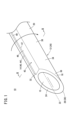
- FIG. 1 is a perspective view of a lymphangiogenesis inducing device according to the present embodiment.
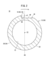
- FIG. 2 is a cross-sectional view taken along line II-II of FIG.
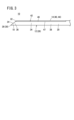
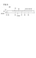
- FIG. 3 is a side view of the lymphangiogenesis induction device of FIG.
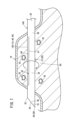
- FIG. 4 is an explanatory diagram showing a wound in a target region of biological tissue caused by the lymphangiogenesis inducing device of FIG.
- FIG. 5 is a perspective view showing a case where the rod-shaped body is solid.
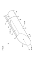
- FIG. 6 is a side view showing the first modified example.
- FIG. 7 is an explanatory diagram showing a wound in a target region of biological tissue caused by the lymphangiogenesis inducing device of FIG.
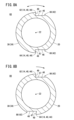
- FIG. 8A is a cross-sectional view showing a second modified example
- FIG. 8B is a cross-sectional view showing a third modified example.
- FIG. 1 is a perspective view of a lymphatic vessel neovascularization induction device 10 according to this embodiment.
- the lymphangiogenesis induction device 10 comprises a rod-shaped body 12 and a wound-inflicting portion 14.
- the rod-shaped body 12 is a rod-shaped member made of metal.
- the rod-shaped body 12 is a straight member.
- the rod-shaped body 12 is a hollow rod-shaped body. Inside the rod-shaped body 12, a hollow space 15 is formed in the axial direction of the rod-shaped body 12.
- the rod-shaped body 12 has an outer diameter large enough to advance inside the biological tissue 16 (see Figure 4).
- the rod-shaped body 12 has a tip portion 18 and a body portion 20 connected to the tip portion 18.
- the tip 18 of the rod-shaped body 12 has a sharp shape that allows it to puncture the biological tissue 16. Specifically, the tip 18 of the rod-shaped body 12 has a blade surface 24 that is cut at an angle to the central axis 22 of the rod-shaped body 12. The tip 18 of the rod-shaped body 12 is capable of puncturing the biological tissue 16. Thus, the rod-shaped body 12 is a puncture device 26.
- the body 20 of the rod-shaped body 12 extends axially along the central axis 22 of the rod-shaped body 12.
- the tip 18 of the rod-shaped body 12 is the portion from the most distal end 28 of the rod-shaped body 12 (the needle tip 30 of the puncture device 26, which is the most distal end 28 of the blade surface 24) to the base end 32 of the blade surface 24. Therefore, the blade surface 24 is not formed on the body 20.
- the outer periphery 34 of the rod-shaped body 12 includes the outer periphery 36 of the tip 18 and the outer periphery 38 of the body 20.
- the wound inflicting portion 14 is formed on the outer periphery 34 of the rod-shaped body 12.
- the wound inflicting portion 14 is an edge portion 40 formed on the outer periphery 34 of the rod-shaped body 12.
- an uneven portion 42 is formed on the outer periphery 34 of the rod-shaped body 12.
- the uneven portion 42 extends along the axial direction of the rod-shaped body 12.
- the uneven portion 42 reaches the blade surface 24.
- the uneven portion 42 is formed on the outer periphery 36 of the tip portion 18 and the outer periphery 38 of the body portion 20. As shown in FIG. 3, the uneven portion 42 is formed on the tip portion 18 and a part of the body portion 20.
- the uneven portion 42 may extend in the axial direction from the tip portion 18 to the base end of the rod-shaped body 12.
- the edge portion 40 is a corner portion 44 of the uneven portion 42.
- the uneven portion 42 is formed by recessing a portion of the outer periphery 34 of the rod-shaped body 12 toward the inside of the rod-shaped body 12.
- the uneven portion 42 has a flat portion 46 and a corner portion 44.
- the flat portion 46 is a portion recessed inward from the outer periphery 34 of the rod-shaped body 12.
- the flat portion 46 is a recessed portion of the uneven portion 42.
- the flat portion 46 is a plane perpendicular to a straight line 48 extending radially from the central axis 22.
- the uneven portion 42 is formed on the outer periphery 34 of the rod-shaped body 12 so as to straddle the straight line 48 extending radially through the central axis 22.
- the corner 44 is formed on the outer peripheral surface 38 of the body 20 and the outer peripheral surface 36 of the tip 18.
- the corner 44 is a convex portion of the uneven portion 42.
- the corner 44 is connected to the flat portion 46 and is a protruding portion (projection) that protrudes radially outward from the flat portion 46.
- the corner 44 is formed at the connection point between the outer peripheral portion 34 and a straight portion 49 that extends radially outward from the flat portion 46. Note that, as shown in FIG. 2, the straight portion 49 is parallel to the straight line 48.
- the flat portion 46 and the straight portion 49 form a groove 47.
- the uneven portion 42 is a groove 47 formed in the outer periphery 34.
- the corners 44 are formed at an acute angle in a cross-sectional view taken from the axial direction of the rod-shaped body 12.
- the corners 44 may be formed even sharper, as shown by the two-dot chain line. This allows the edge portion 40 to be formed with an even more acute angle.
- lymphatic vessel neovascularization induction device 10 The method of using the lymphatic vessel neovascularization induction device 10 according to this embodiment will be described with reference to FIG. 4.
- the user inserts the rod-shaped body 12 into the living tissue 16 by puncturing the tip 18 of the rod-shaped body 12.
- the user inserts the rod-shaped body 12 into the living tissue 16 in the axial direction, thereby inserting the wound inflicting part 14 up to the target site 50 inside the living tissue 16.
- the user rotates the rod-shaped body 12 once (360°) around the central axis 22 (see Figures 1 and 2).
- the rod-shaped body 12 is rotated once in the direction of rotation shown by the solid line.
- the acute-angled edge part 40 abuts against the target site 50.
- the user can supply a medicinal solution or a thread-like device to the target site 50 from the outside through the hollow portion 15 of the rod-shaped body 12.
- lymphatic vessel neonatogenesis induction device 10 The effects of the lymphatic vessel neonatogenesis induction device 10 according to this embodiment will be explained.
- the edge portion 40 which is the wound inflicting portion 14, is formed on the outer periphery 34 of the rod-shaped body 12, so the lymphatic vessel angiogenesis induction device 10 can be easily constructed.
- wounds 52 can be easily inflicted on the target site 50.
- wounds 52 can be inflicted over a wide area with fewer rotations.
- the lymphatic vessel angiogenesis induction device 10 has a small number of parts, so costs can be reduced.
- lymphatic vessel neogenesis induction device 10 By configuring the lymphatic vessel neogenesis induction device 10 in this manner, it is possible to insert the rod-shaped body 12 into the biological tissue 16 and create a minute wound 52 in the target site 50 without the need for complicated procedures. By creating a minute wound 52 in the target site 50, it is possible to promote the creation of lymphatic vessels during the healing process of the wound 52.
- edge portion 40 is formed at an acute angle, when the rod-shaped body 12 is rotated around the central axis 22 at the target site 50 of the biological tissue 16, a fine wound 52 can be easily created at the target site 50.
- the corners 44 of the uneven portion 42 become the edge portion 40, so that the edge portion 40 can be easily formed.
- a fine wound 52 can be easily created at the target portion 50.
- the uneven portion 42 is a groove 47
- the corners 44 of the groove 47 become the edge portion 40. This makes it easy to form the edge portion 40.
- the edge portion 40 extends along the axial direction over the entire rod-shaped body 12, so that when the rod-shaped body 12 is rotated about the central axis 22 relative to the target site 50 of the biological tissue 16, fine wounds 52 can be easily and widely created.
- the edge portion 40 since the edge portion 40 only needs to be formed straight along the axial direction of the rod-shaped body 12, the edge portion 40 can be formed easily and simply.
- the edge portion 40 (uneven portion 42) is formed on the tip 18 and body 20 of the rod-shaped body 12, when the tip 18 of the rod-shaped body 12 is inserted into the biological tissue 16 and the rod-shaped body 12 is displaced about the central axis 22 relative to a target site 50 of the biological tissue 16, a fine wound 52 can be created in the target site 50 without damaging the skin of the living body.
- the rod-shaped body 12 has a tip 18 that can be punctured into the biological tissue 16, the rod-shaped body 12 can be used as a puncture device 26.
- the length of the uneven portion 42 is preferably 1.0 cm to 15.0 cm, and more preferably 5.0 cm to 10.0 cm. This makes it easy to create the wound 52 and place the thread-like device.
- the rod-shaped body 12 is a hollow rod-shaped body, it is possible to supply a medicinal solution or a thread-like device to the target site 50 from the outside via the rod-shaped body 12.
- an uneven portion 42 is formed on the outer periphery 34 so as to straddle a straight line 48 that passes through the central axis 22 of the rod-shaped body 12 and extends radially. This makes it easy to form the edge portion 40, as the corners 44 of the uneven portion 42 become the edge portion 40.
- a fine wound 52 can be easily created at the target site 50.
- the rod-shaped body 12 may be a solid rod-shaped body. Since the rod-shaped body 12 is a solid rod-shaped body, the rod-shaped body 12 is sturdy and bending is suppressed, and the lymphatic vessel angiogenesis induction device 10 can be easily formed.
- the shape of the rod-shaped body 12 is not limited to a straight line.
- the rod-shaped body 12 may also be slightly curved.
- the rod-shaped body 12 does not have to have a blade surface 24 formed.
- the rod-shaped body 12 only needs to be capable of being inserted into the biological tissue 16. For example, during surgery on the biological tissue 16, the biological tissue 16 is incised, and therefore the rod-shaped body 12 can be inserted into the incised biological tissue 16.
- the wound 52 is created in the target area 50 by rotating the rod-shaped body 12 once (360°) around the central axis 22.
- the blade surface 24 may be cut on one side or on two sides. If it is cut on one side, an edge portion 40 (uneven portion 42) may be formed on the blade surface 24. If it is cut on two sides, the rod-shaped body 12 can be easily inserted into the biological tissue 16.
- the uneven portion 42 may be connected to the hollow portion 15.
- the uneven portion 42 may be a hole.
- the uneven portion 42 may also be a bottomed hole or depression.
- FIG. 6 is a side view of a lymphatic vessel angiogenesis induction device 140 according to a first modified example.
- FIG. 7 is an explanatory diagram showing a wound 52 in a target site 50 of biological tissue 16 by a lymphatic vessel angiogenesis induction device 140.
- an edge portion 142 is not formed at the tip 18 of the rod-shaped body 12, and an edge portion 142 is formed at the body 20.
- an edge portion 142 is formed at a location away from the tip 18 on the body 20 of the rod-shaped body 12.
- the edge portion 142 is formed in a part of the body 20.
- FIG. 7 shows a wound 52 in the target site 50 from the edge portion 142 in the first modified example.
- the user also inserts the rod-shaped body 12 into the biological tissue 16 by puncturing the tip 18 of the rod-shaped body 12 into the biological tissue 16.
- the user inserts the rod-shaped body 12 into the biological tissue 16 so that the edge portion 142 is located at the target site 50.
- the edge portion 142 is not formed on the tip portion 18, but is formed on a part of the body portion 20. Therefore, the user advances the rod-shaped body 12 into the biological tissue 16 and exposes the tip portion 18 of the rod-shaped body 12 to the outside from the biological tissue 16. In other words, the tip portion 18 of the rod-shaped body 12 penetrates the biological tissue 16. As a result, the edge portion 142 is located at the target site 50. In this case, the user also inserts the rod-shaped body 12 so that the edge portion 142 is not located on the skin of the biological tissue 16.
- the user rotates the rod-shaped body 12 once in the direction of rotation of the solid line shown in FIG. 7.
- the acute edge portion 142 comes into contact with the target area 50, and a fine wound 52 is created in the target area 50 from the edge portion 142.
- the user pulls the rod-shaped body 12 out of the biological tissue 16 by retracting the rod-shaped body 12 along the axial direction. Therefore, even in the first modified example, the creation of a fine wound 52 in the target area 50 can be promoted, which promotes the formation of new lymphatic vessels during the healing process of the wound 52.
- lymphatic vessel neoplasia induction device 140 The effects of the lymphatic vessel neoplasia induction device 140 according to the first modified example will now be described.
- an edge portion 142 is formed on the body portion 20 of the rod-shaped body 12.
- the length of the uneven portion 42 is preferably 1.0 cm to 15.0 cm, and more preferably 5.0 cm to 10.0 cm. This makes it easy to create the wound 52 and place the thread-like device.
- the length from the tip 28 to the uneven portion 42 along the axial direction and the length from the base end of the rod-shaped body 12 to the uneven portion 42 along the axial direction are preferably 0.5 cm to 13.0 cm, and more preferably 1.0 cm to 8.0 cm. This allows the edge portion 142 to be easily positioned at the target site 50. It also makes it easier for the user to operate the rod-shaped body 12.
- FIG. 8A is a cross-sectional view of a lymphangiogenesis induction device 60 according to a second modified example.
- multiple edge portions 62, 64 are formed at intervals in the circumferential direction of the outer periphery 34 of the rod-shaped body 12.
- two edge portions 62, 64 are formed on the outer periphery 34 of the rod-shaped body 12 so as to face each other across the central axis 22. That is, two uneven portions 66, 68 are formed at an interval of 180°, and the corners 44 of the two uneven portions 66, 68 are formed as two edge portions 62, 64.
- the two edge portions 62, 64 face each other along the circumferential direction.
- the upper edge portion 62 is an edge portion with an acute angle toward the rotation direction of the solid line (clockwise direction in FIG. 8A).
- the lower edge 64 is an acute-angled edge in the direction of rotation of the dashed line (counterclockwise in FIG. 8A).
- the user rotates the rod-shaped body 12 once around the central axis 22 in the direction of rotation of the solid line or the direction of rotation of the dashed line in Figure 8A.
- the upper edge portion 62 abuts against the target site 50, and the edge portion 62 inflicts a fine wound 52 on the target site 50.
- the lower edge portion 64 abuts against the target site 50, and the edge portion 64 inflicts a fine wound 52 on the target site 50. Therefore, in the second modified example, regardless of the direction in which the rod-shaped body 12 is rotated around the central axis 22, the edge portions 62, 64 can inflict a fine wound 52 on the target site 50.
- lymphatic vessel neoplasia induction device 60 The effect of the lymphatic vessel neoplasia induction device 60 according to the second modified example will now be described.
- the two edge portions 62, 64 are formed on the outer periphery 34 so that they face each other across the central axis 22, so that a minute wound 52 can be created in the target area 50 of the biological tissue 16 simply by rotating the rod-shaped body 12 180° around the central axis 22.
- FIG. 8B is a cross-sectional view of a lymphatic vessel angiogenesis induction device 80 according to a third modified example.
- two edge portions 82, 84 are formed on the outer periphery 34 of the rod-shaped body 12 so as to face each other across the central axis 22.
- the two edge portions 82, 84 are edge portions with acute angles facing the direction of rotation of the solid line.
- two uneven portions 86, 88 are formed on the outer periphery 34 of the rod-shaped body 12 so as to face each other across the central axis 22, and the corners 44 of the two uneven portions 86, 88 are formed as the two edge portions 82, 84.
- the user rotates the rod-shaped body 12 180° (half a rotation) around the central axis 22 in the direction of rotation of the solid line. This causes each of the two edge portions 82, 84 to come into contact with the target site 50, and fine wounds 52 are inflicted on the target site 50 from the edges 82, 84. Therefore, in the third modified example, by rotating the rod-shaped body 12 through a rotation angle smaller than one rotation, fine wounds 52 can be inflicted on the target site 50 from the edges 82, 84.
- the lymphatic vessel neoplasia induction device 80 according to the third modified example also provides the same effects as the second modified example.
- three or more edge portions 62, 64, 82, 84 may be formed on the outer periphery 34. This makes it possible to create minute wounds 52 in the target area 50 simply by rotating the rod-shaped body 12 through an angle of rotation smaller than the rotation angle of one rotation (360°).
- the present invention is not limited to the above disclosure, and various configurations may be adopted without departing from the gist of the present invention.
Landscapes
- Health & Medical Sciences (AREA)
- Life Sciences & Earth Sciences (AREA)
- Surgery (AREA)
- Public Health (AREA)
- Animal Behavior & Ethology (AREA)
- Engineering & Computer Science (AREA)
- Biomedical Technology (AREA)
- Heart & Thoracic Surgery (AREA)
- Veterinary Medicine (AREA)
- General Health & Medical Sciences (AREA)
- Nuclear Medicine, Radiotherapy & Molecular Imaging (AREA)
- Molecular Biology (AREA)
- Medical Informatics (AREA)
- Pathology (AREA)
- Vascular Medicine (AREA)
- Anesthesiology (AREA)
- Hematology (AREA)
- Prostheses (AREA)
- Medicines That Contain Protein Lipid Enzymes And Other Medicines (AREA)
Priority Applications (5)
| Application Number | Priority Date | Filing Date | Title |
|---|---|---|---|
| JP2025508314A JPWO2024195579A1 (cg-RX-API-DMAC7.html) | 2023-03-20 | 2024-03-08 | |
| AU2024239860A AU2024239860A1 (en) | 2023-03-20 | 2024-03-08 | Lymphangiogenesis inducing device |
| EP24774718.1A EP4623845A4 (en) | 2023-03-20 | 2024-03-08 | DEVICE FOR THE INDUCTION OF LYMPHANGIogenesis |
| CN202480012780.3A CN120693117A (zh) | 2023-03-20 | 2024-03-08 | 淋巴管新生诱导设备 |
| US19/333,679 US20260013898A1 (en) | 2023-03-20 | 2025-09-19 | Lymphangiogenesis inducing device |
Applications Claiming Priority (2)
| Application Number | Priority Date | Filing Date | Title |
|---|---|---|---|
| JP2023-043801 | 2023-03-20 | ||
| JP2023043801 | 2023-03-20 |
Related Child Applications (1)
| Application Number | Title | Priority Date | Filing Date |
|---|---|---|---|
| US19/333,679 Continuation US20260013898A1 (en) | 2023-03-20 | 2025-09-19 | Lymphangiogenesis inducing device |
Publications (1)
| Publication Number | Publication Date |
|---|---|
| WO2024195579A1 true WO2024195579A1 (ja) | 2024-09-26 |
Family
ID=92842095
Family Applications (1)
| Application Number | Title | Priority Date | Filing Date |
|---|---|---|---|
| PCT/JP2024/008922 Ceased WO2024195579A1 (ja) | 2023-03-20 | 2024-03-08 | リンパ管新生誘導デバイス |
Country Status (6)
| Country | Link |
|---|---|
| US (1) | US20260013898A1 (cg-RX-API-DMAC7.html) |
| EP (1) | EP4623845A4 (cg-RX-API-DMAC7.html) |
| JP (1) | JPWO2024195579A1 (cg-RX-API-DMAC7.html) |
| CN (1) | CN120693117A (cg-RX-API-DMAC7.html) |
| AU (1) | AU2024239860A1 (cg-RX-API-DMAC7.html) |
| WO (1) | WO2024195579A1 (cg-RX-API-DMAC7.html) |
Citations (2)
| Publication number | Priority date | Publication date | Assignee | Title |
|---|---|---|---|---|
| JP2022090253A (ja) * | 2020-12-07 | 2022-06-17 | テルモ株式会社 | リンパ管新生誘導デバイス |
| WO2023100890A1 (ja) * | 2021-11-30 | 2023-06-08 | テルモ株式会社 | リンパ管新生誘導デバイス |
Family Cites Families (4)
| Publication number | Priority date | Publication date | Assignee | Title |
|---|---|---|---|---|
| WO2002062226A1 (en) * | 2001-02-05 | 2002-08-15 | Tyco Healthcare Group Lp | Biopsy apparatus and method |
| CA2876545C (en) * | 2012-06-14 | 2021-03-30 | Sanoculis Ltd. | A medical device, assembly and method for creating a channel in soft tissue |
| US10549072B2 (en) * | 2015-10-28 | 2020-02-04 | Becton, Dickinson And Company | Integrated catheter with independent fluid paths |
| US10960147B2 (en) * | 2018-04-20 | 2021-03-30 | Flextronics Ap, Llc | Flex needle |
-
2024
- 2024-03-08 JP JP2025508314A patent/JPWO2024195579A1/ja active Pending
- 2024-03-08 EP EP24774718.1A patent/EP4623845A4/en active Pending
- 2024-03-08 CN CN202480012780.3A patent/CN120693117A/zh active Pending
- 2024-03-08 AU AU2024239860A patent/AU2024239860A1/en active Pending
- 2024-03-08 WO PCT/JP2024/008922 patent/WO2024195579A1/ja not_active Ceased
-
2025
- 2025-09-19 US US19/333,679 patent/US20260013898A1/en active Pending
Patent Citations (2)
| Publication number | Priority date | Publication date | Assignee | Title |
|---|---|---|---|---|
| JP2022090253A (ja) * | 2020-12-07 | 2022-06-17 | テルモ株式会社 | リンパ管新生誘導デバイス |
| WO2023100890A1 (ja) * | 2021-11-30 | 2023-06-08 | テルモ株式会社 | リンパ管新生誘導デバイス |
Non-Patent Citations (3)
| Title |
|---|
| KOTARO SUEHIRO, ANN VASC SURG, vol. 62, January 2020 (2020-01-01), pages 258 - 262 |
| See also references of EP4623845A1 |
| TAKUMI YAMAMOTO ET AL.: "SCIP flap transplantation for lymphedema", PEPARS, vol. 150, 2019, pages 54 - 64 |
Also Published As
| Publication number | Publication date |
|---|---|
| JPWO2024195579A1 (cg-RX-API-DMAC7.html) | 2024-09-26 |
| CN120693117A (zh) | 2025-09-23 |
| EP4623845A1 (en) | 2025-10-01 |
| AU2024239860A1 (en) | 2025-10-02 |
| EP4623845A4 (en) | 2026-03-04 |
| US20260013898A1 (en) | 2026-01-15 |
Similar Documents
| Publication | Publication Date | Title |
|---|---|---|
| US10349975B2 (en) | Tri-fluted vascular access needle | |
| EP2497430A1 (en) | Foreskin-plaster and fixator for circumcision surgery | |
| US11904152B2 (en) | Infiltration cannula with dual angle configuration | |
| CA2566490A1 (en) | Device and method for treating varicose veins | |
| CN201101549Y (zh) | 静脉切除器 | |
| JP2017535394A (ja) | 欠陥のある血管、体腔及び体管を治療するための医療デバイス | |
| JP2022090253A (ja) | リンパ管新生誘導デバイス | |
| EP4623845A1 (en) | Lymphangiogenesis induction device | |
| US20240050115A1 (en) | Method for percutaneous treatment of vessels | |
| US20240189506A1 (en) | Infiltration cannula with dual angle configuration | |
| EP3206590B1 (en) | Catheter comprising a cutting element | |
| US12508030B2 (en) | Apparatus and methods for closing vessels | |
| RU2573337C1 (ru) | Способ катетеризации внутренней яремной вены | |
| CN101438972B (zh) | 静脉切除器 | |
| CN109223116B (zh) | 一种新型微创手术切除体表皮下肿物的器械 | |
| CN113855554A (zh) | 一种用于增强穴位启动靶点刺激的针灸针及其制造方法 | |
| CN210144716U (zh) | 一种用于包皮环切的手术套件 | |
| WO2025069672A1 (ja) | リンパ管新生誘導デバイス | |
| WO2025069673A1 (ja) | リンパ管新生誘導デバイス | |
| JP2012020042A (ja) | 皮下注射針 | |
| CN217611230U (zh) | 一种治疗下肢静脉曲张的血管闭合器 | |
| CN208389086U (zh) | 一种颅骨板障静脉输液装置 | |
| JP7411673B2 (ja) | 止血器具 | |
| CN217244670U (zh) | 一种新型窄刃针刀 | |
| CN217853211U (zh) | 一种具有新月形针尖的针灸针 |
Legal Events
| Date | Code | Title | Description |
|---|---|---|---|
| 121 | Ep: the epo has been informed by wipo that ep was designated in this application |
Ref document number: 24774718 Country of ref document: EP Kind code of ref document: A1 |
|
| WWE | Wipo information: entry into national phase |
Ref document number: 2024774718 Country of ref document: EP |
|
| ENP | Entry into the national phase |
Ref document number: 2025508314 Country of ref document: JP Kind code of ref document: A |
|
| WWE | Wipo information: entry into national phase |
Ref document number: 2025508314 Country of ref document: JP |
|
| ENP | Entry into the national phase |
Ref document number: 2024774718 Country of ref document: EP Effective date: 20250627 |
|
| WWE | Wipo information: entry into national phase |
Ref document number: 202480012780.3 Country of ref document: CN |
|
| WWE | Wipo information: entry into national phase |
Ref document number: AU2024239860 Country of ref document: AU |
|
| WWP | Wipo information: published in national office |
Ref document number: 202480012780.3 Country of ref document: CN |
|
| WWP | Wipo information: published in national office |
Ref document number: 2024774718 Country of ref document: EP |
|
| ENP | Entry into the national phase |
Ref document number: 2024239860 Country of ref document: AU Date of ref document: 20240308 Kind code of ref document: A |
|
| NENP | Non-entry into the national phase |
Ref country code: DE |