WO2024195427A1 - 駆動装置 - Google Patents
駆動装置 Download PDFInfo
- Publication number
- WO2024195427A1 WO2024195427A1 PCT/JP2024/006448 JP2024006448W WO2024195427A1 WO 2024195427 A1 WO2024195427 A1 WO 2024195427A1 JP 2024006448 W JP2024006448 W JP 2024006448W WO 2024195427 A1 WO2024195427 A1 WO 2024195427A1
- Authority
- WO
- WIPO (PCT)
- Prior art keywords
- gear
- motor
- power module
- smoothing capacitor
- shaft
- Prior art date
- Legal status (The legal status is an assumption and is not a legal conclusion. Google has not performed a legal analysis and makes no representation as to the accuracy of the status listed.)
- Ceased
Links
Images



Classifications
-
- H—ELECTRICITY
- H02—GENERATION; CONVERSION OR DISTRIBUTION OF ELECTRIC POWER
- H02K—DYNAMO-ELECTRIC MACHINES
- H02K11/00—Structural association of dynamo-electric machines with electric components or with devices for shielding, monitoring or protection
- H02K11/30—Structural association with control circuits or drive circuits
- H02K11/33—Drive circuits, e.g. power electronics
-
- B—PERFORMING OPERATIONS; TRANSPORTING
- B60—VEHICLES IN GENERAL
- B60K—ARRANGEMENT OR MOUNTING OF PROPULSION UNITS OR OF TRANSMISSIONS IN VEHICLES; ARRANGEMENT OR MOUNTING OF PLURAL DIVERSE PRIME-MOVERS IN VEHICLES; AUXILIARY DRIVES FOR VEHICLES; INSTRUMENTATION OR DASHBOARDS FOR VEHICLES; ARRANGEMENTS IN CONNECTION WITH COOLING, AIR INTAKE, GAS EXHAUST OR FUEL SUPPLY OF PROPULSION UNITS IN VEHICLES
- B60K17/00—Arrangement or mounting of transmissions in vehicles
- B60K17/04—Arrangement or mounting of transmissions in vehicles characterised by arrangement, location or kind of gearing
- B60K17/12—Arrangement or mounting of transmissions in vehicles characterised by arrangement, location or kind of gearing of electric gearing
-
- B—PERFORMING OPERATIONS; TRANSPORTING
- B60—VEHICLES IN GENERAL
- B60K—ARRANGEMENT OR MOUNTING OF PROPULSION UNITS OR OF TRANSMISSIONS IN VEHICLES; ARRANGEMENT OR MOUNTING OF PLURAL DIVERSE PRIME-MOVERS IN VEHICLES; AUXILIARY DRIVES FOR VEHICLES; INSTRUMENTATION OR DASHBOARDS FOR VEHICLES; ARRANGEMENTS IN CONNECTION WITH COOLING, AIR INTAKE, GAS EXHAUST OR FUEL SUPPLY OF PROPULSION UNITS IN VEHICLES
- B60K17/00—Arrangement or mounting of transmissions in vehicles
- B60K17/04—Arrangement or mounting of transmissions in vehicles characterised by arrangement, location or kind of gearing
- B60K17/06—Arrangement or mounting of transmissions in vehicles characterised by arrangement, location or kind of gearing of change-speed gearing
-
- H—ELECTRICITY
- H02—GENERATION; CONVERSION OR DISTRIBUTION OF ELECTRIC POWER
- H02K—DYNAMO-ELECTRIC MACHINES
- H02K11/00—Structural association of dynamo-electric machines with electric components or with devices for shielding, monitoring or protection
- H02K11/30—Structural association with control circuits or drive circuits
-
- H—ELECTRICITY
- H02—GENERATION; CONVERSION OR DISTRIBUTION OF ELECTRIC POWER
- H02K—DYNAMO-ELECTRIC MACHINES
- H02K7/00—Arrangements for handling mechanical energy structurally associated with dynamo-electric machines, e.g. structural association with mechanical driving motors or auxiliary dynamo-electric machines
- H02K7/10—Structural association with clutches, brakes, gears, pulleys or mechanical starters
- H02K7/116—Structural association with clutches, brakes, gears, pulleys or mechanical starters with gears
-
- H—ELECTRICITY
- H02—GENERATION; CONVERSION OR DISTRIBUTION OF ELECTRIC POWER
- H02M—APPARATUS FOR CONVERSION BETWEEN AC AND AC, BETWEEN AC AND DC, OR BETWEEN DC AND DC, AND FOR USE WITH MAINS OR SIMILAR POWER SUPPLY SYSTEMS; CONVERSION OF DC OR AC INPUT POWER INTO SURGE OUTPUT POWER; CONTROL OR REGULATION THEREOF
- H02M7/00—Conversion of AC power input into DC power output; Conversion of DC power input into AC power output
- H02M7/003—Constructional details, e.g. physical layout, assembly, wiring or busbar connections
-
- B—PERFORMING OPERATIONS; TRANSPORTING
- B60—VEHICLES IN GENERAL
- B60Y—INDEXING SCHEME RELATING TO ASPECTS CROSS-CUTTING VEHICLE TECHNOLOGY
- B60Y2200/00—Type of vehicle
- B60Y2200/90—Vehicles comprising electric prime movers
- B60Y2200/91—Electric vehicles
-
- Y—GENERAL TAGGING OF NEW TECHNOLOGICAL DEVELOPMENTS; GENERAL TAGGING OF CROSS-SECTIONAL TECHNOLOGIES SPANNING OVER SEVERAL SECTIONS OF THE IPC; TECHNICAL SUBJECTS COVERED BY FORMER USPC CROSS-REFERENCE ART COLLECTIONS [XRACs] AND DIGESTS
- Y02—TECHNOLOGIES OR APPLICATIONS FOR MITIGATION OR ADAPTATION AGAINST CLIMATE CHANGE
- Y02T—CLIMATE CHANGE MITIGATION TECHNOLOGIES RELATED TO TRANSPORTATION
- Y02T10/00—Road transport of goods or passengers
- Y02T10/60—Other road transportation technologies with climate change mitigation effect
- Y02T10/64—Electric machine technologies in electromobility
Definitions
- the technology disclosed in this specification relates to a drive device.
- JP 2020-40578 A discloses a drive unit that includes a motor and an electric motor control device that controls the motor.
- the electric motor control device is disposed above the motor.
- Vehicles have a large number of parts that must be mounted in a limited space. There is a demand for effective use of the mounting space.
- This specification provides technology that can make effective use of space.
- the first aspect disclosed in this specification relates to a drive device.
- the drive device includes a motor having a motor shaft, a first gear that rotates around the central axis of the motor shaft, and an inverter having a plurality of components used to control the motor, and at least a portion of the inverter may overlap with the motor in the central axis direction, and at least a portion of the inverter may overlap with the first gear in the radial direction of the first gear.
- the inverter is placed in the space around the motor shaft that is created by the dimensional difference between the motor and the first gear. This allows the space around the motor shaft to be used effectively.
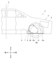
- FIG. 1 is a side view of an electric vehicle equipped with a drive device according to an embodiment of the present invention
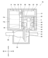
- FIG. 2 shows a side view of the drive unit with the casing removed.
- FIG. 2 shows a schematic internal configuration diagram of a drive device.
- FIG. FIG. FIG. 4 is a side view of the drive device for explaining the configuration of the busbar unit.
- FIG. FIG. A block diagram of the cooling circuit is shown.
- the multiple components may include a power module having multiple switching elements, a smoothing capacitor, and a noise filter, and may be arranged from top to bottom in the order of the power module, the smoothing capacitor, and the noise filter.
- the length of each of the power module, the smoothing capacitor, and the noise filter along the rotational direction of the first gear is longer than the length of the first gear along the radial direction, and the range from the end of the power module opposite the smoothing capacitor in the rotational direction of the first gear to the end of the noise filter opposite the smoothing capacitor may be 180° or more around the central axis.
- the longitudinal directions of the power module, smoothing capacitor, and noise filter are aligned along the direction of rotation of the first gear. This allows the space around the first gear to be used effectively.
- the second or third aspect described above may further include a second gear that meshes with the first gear, and the first gear may be disposed between the second gear and the power module.
- the power module is a relatively large component among the multiple components of the inverter. By placing the power module on the opposite side of the first gear from the second gear, the power module and the second gear can be positioned efficiently.
- the second gear may be disposed below the first gear and the power module.
- the torque of the motor is transmitted downward from the first gear to the second gear.
- This configuration allows the motor to be positioned above the drive shaft.
- the power module and second gear can be positioned efficiently, without having to significantly change the position of the motor relative to the drive shaft.
- the device in any one of the first to fifth aspects above, includes a plurality of shafts including the motor shaft and a drive shaft, and one or more gears arranged on each of the plurality of shafts, and the one or more gears arranged on the motor shaft may include the first gear.
- the torque of the motor can be transmitted to the drive shaft via multiple gears.
- the outer diameter of the first gear may be the smallest among the outer diameters of the one or more gears.
- the multiple components of the inverter are arranged around the smallest first gear among the multiple gears between the motor and the axle, making it possible to make effective use of space.
- FIG. 1 is a schematic diagram showing a front part of an electric vehicle 2 equipped with a drive device 10 of the embodiment, as seen from the side.
- the electric vehicle 2 includes a body 4, a battery pack 6, a suspension member 8, and a pair of front wheels 100.
- the electric vehicle 2 is equipped with a pair of rear wheels, a control device, and a plurality of other devices for the operation of the electric vehicle 2.
- configurations other than the drive device 10 and the suspension member 8 are shown with dashed lines.
- the outer diameter shapes of each part are shown in a simplified manner.
- the electric vehicle 2 includes vehicles that use an electric motor for at least part of the traveling, such as hybrid vehicles and fuel cell vehicles.
- vehicles that use an electric motor for at least part of the traveling such as hybrid vehicles and fuel cell vehicles.
- “upper”, “lower”, “left”, “right”, “front”, and “rear” are described based on the coordinate system in the figure.
- the drive unit 10 is located forward of a front seat (not shown) of the electric vehicle 2.
- the drive unit 10 is disposed in a compartment forward of the passenger space in which the occupants of the electric vehicle 2 are located.
- the drive unit 10 is disposed between a pair of front wheels 100 located at both ends of the electric vehicle 2 in the left-right direction.
- the drive unit 10 is located rearward of a front trunk 9 located near the front end of the electric vehicle 2.
- the front trunk 9 is separated from the passenger space and is a space in which luggage can be carried.
- the drive unit 10 is disposed forward of a vehicle center C of the electric vehicle 2 in the front-rear direction.
- the drive unit 10 is fixed to a suspension member 8.
- the suspension member 8 is configured as part of a suspension unit (not shown) that includes springs, dampers, etc. that are arranged on each of the pair of front wheels 100.
- the suspension member 8 holds the springs, dampers, etc. In this way, the suspension unit is mounted on the electric vehicle 2.
- the drive unit 10 is protected by a casing 12.
- Figure 2 shows a right side view of the inside of the casing 12 with the right side wall of the casing 12 removed.
- the drive unit 10 includes a motor 14, a gear unit 30, an inverter 20, and a drive shaft 90.
- the casing 12 houses the motor 14, the gear unit 30, the inverter 20, and the drive shaft 90.
- the casing 12 defines a housing space in which multiple parts are combined.
- the inverter 20 converts the DC power of the battery pack 6 into AC power suitable for driving the motor 14.
- the battery pack 6 is disposed below a floor panel (not shown) of the electric vehicle 2.
- the battery pack 6 supplies power to the drive unit 10. This causes the drive unit 10 to drive a pair of front wheels 100.
- the drive unit 10 also functions as a generator.
- the battery pack 6 stores the power supplied from the drive unit 10.
- the inverter 20 supplies AC power to the motor 14.
- the motor 14 is driven by the AC power from the inverter 20.
- the torque of the motor 14 is transmitted to the drive shaft 90 via the gear unit 30.
- the drive shaft 90 transmits the torque of the motor 14 to each of the pair of front wheels 100, thereby rotating the pair of front wheels 100. This drives the electric vehicle 2.
- the inverter 20 converts the AC power generated by the motor 14 into DC power and supplies it to the battery pack 6.
- the motor 14 is disposed at the upper rear of the drive unit 10.
- FIG. 3 shows the internal structure of the drive unit 10 from the perspective of the lower front to the upper rear. Note that in FIG. 3, the configuration of the inverter 20 is partially omitted in order to explain the gear unit 30.
- the motor 14 comprises a main body 14a having a rotor 14c and a stator 14d, and a motor shaft 14b extending from the rotor 14c.
- the stator 14d has a cylindrical shape. Although not shown, the stator 14d comprises a stator core having multiple teeth and coils arranged on the multiple teeth.
- the rotor 14c is disposed on the inner circumference of the stator 14d.
- the outer peripheral surface of the rotor 14c faces the inner peripheral surface of the stator 14d.
- the rotor 14c has multiple permanent magnets arranged on the outer peripheral surface of the rotor 14c such that the polarity alternates in the circumferential direction.
- the motor shaft 14b is arranged coaxially with the center of rotation of the rotor 14c.
- the motor shaft 14b extends linearly from the main body 14a to the right.
- the gear unit 30 includes a shaft gear 32, a counter gear 34, a counter gear 42, a ring gear 50, a differential gear 52, and a shaft 44.
- the shaft gear 32, the counter gear 34, the counter gear 42, and the ring gear 50 each have a cylindrical shape with a plurality of teeth arranged on the outer circumferential surface. Teeth arranged on the shaft gear 32, the counter gear 34, the counter gear 42, and the ring gear 50 are not shown.
- the shaft gear 32 is attached to the motor shaft 14b.
- the motor shaft 14b is rotatably supported with respect to the casing 12 by bearings 36 and 38 attached to the casing 12. In the drive device 10, the gear unit 30 is in direct contact with the motor 14, so that the gear unit 30 and the motor 14 can be easily mechanically connected to each other.
- the counter gear 34 meshes with the shaft gear 32 and rotates with the rotation of the shaft gear 32.
- the counter gear 34 is disposed below and in front of the shaft gear 32.
- the counter gear 34 is attached to a shaft 44.
- the shaft 44 is disposed parallel to the motor shaft 14b.
- the shaft 44 is disposed below and in front of the motor shaft 14b.
- the shaft 44 is rotatably supported relative to the casing 12 by bearings 46 and 48 attached to the casing 12.
- the counter gear 42 is attached to the shaft 44.
- the counter gear 42 is connected coaxially to the counter gear 34.
- the counter gear 42 rotates with the rotation of the counter gear 34.
- the ring gear 50 meshes with the counter gear 42 and rotates with the rotation of the counter gear 42.
- the ring gear 50 is disposed below and in front of the counter gear 42.
- the ring gear 50 rotates around the central axis Y (see FIG. 2).
- the ring gear 50 is attached to the differential gear 52.
- the differential gear 52 rotates with the rotation of the ring gear 50.
- the differential gear 52 is a gear mechanism that rotates each of the pair of front wheels 100 independently by the rotation of the ring gear 50.
- the differential gear 52 is disposed below and in front of the ring gear 50.
- the differential gear 52 drives the drive shaft 90.
- the drive shaft 90 is disposed below and in front of the shaft 44. When the rotation of the motor 14 is transmitted to the drive shaft 90, the drive shaft 90 rotates around the central axis Y, and the pair of front wheels 100 rotate around the drive shaft 90. This causes the electric vehicle 2 to run.
- the counter gear 34 is disposed in front of and below the shaft gear 32.
- the counter gear 42 is disposed coaxially with the counter gear 34, i.e., aligned in the left-right direction.
- the ring gear 50 is disposed in front of and below the counter gear 42.
- the differential gear 52 is disposed in front of and below the ring gear 50. In other words, they are aligned rearward and upward from the differential gear 52 through the ring gear 50, counter gear 42, and counter gear 34 to the shaft gear 32.
- the upper surface 12a and lower surface 12b of the casing 12 that houses the gear unit 30 are inclined upward from the front to the rear, i.e., toward the center C of the vehicle.
- the central axis X of the motor shaft 14b i.e., the central axis X of the shaft gear 32
- the central axis Y of the ring gear 50 are arranged parallel to each other.
- most of the counter gear 34 is located below a plane P that connects the central axis X of the motor shaft 14b and the central axis Y of the ring gear 50.
- the counter gear 42 is located entirely below the plane P.
- the counter gear 34 may be located entirely below the plane P.
- the outer diameter of the counter gear 34 (i.e., the diameter of a circle connecting the tips of the teeth arranged along the outer circumference of the gear) is larger than the outer diameter of the shaft gear 32.
- the outer diameter of the ring gear 50 is larger than the outer diameter of the counter gear 42.
- the shaft gear 32 has the smallest outer diameter.
- a gear that is the same as or smaller than the shaft gear 32 may be arranged in the gear unit 30.
- the inverter 20 is connected to the battery pack 6 by a power cable 7.
- the inverter 20 is a device for converting DC power of the battery pack 6 into AC power suitable for driving the motor 14.
- the inverter 20 is a high-voltage component to which high-voltage power is applied.
- “high voltage” refers to an operating voltage of more than 60V DC and less than or equal to 1500V, or more than 30V AC (effective value) and less than or equal to 1000V (effective value).
- the inverter 20 is a device for converting AC power from the motor 14 into DC power suitable for the battery pack 6. In a modified example, the inverter 20 may convert DC power into AC power, but may not convert AC power into DC power.
- the inverter 20 includes a power module 22, a smoothing capacitor 24, a noise filter 26, a connector 28, and busbar units 60 and 70 (see FIG. 6).
- the power supplied from the battery pack 6 to the inverter 20 is input from the connector 28, passes through the noise filter 26, the busbar unit 60, the smoothing capacitor 24, the noise filter 26, and the busbar unit 70 in that order, and is supplied from the busbar unit 70 to the motor 14.
- the connector 28 has a terminal (not shown) that is connected to the terminal of the power cable 7, and a cover 28a that surrounds the terminal.
- the connector 28 penetrates the casing 12 and extends from the outside to the inside of the casing 12.
- the terminal extends in the left-right direction and is connected to the power cable 7.
- the cover 28a protrudes downward and rearward from the bottom surface 12b of the casing 12.
- the cover 28a is disposed in a space located below the bottom surface 12b.
- the cover 28a is disposed below the rear end of the casing 12 and rearward of the lowest end.
- the terminals of the connector 28 extend to the noise filter 26.
- the noise filter 26 is an electromagnetic compatibility (EMC (short for Electro Magnetic Compatibility)) noise filter.
- EMC Electro Magnetic Compatibility
- the noise filter 26 has circuit components (not shown) such as a capacitor and a choke coil, and a casing 26a that houses the circuit components.
- the noise filter 26 is housed in the casing 12.
- the casing 26a is attached to the inner wall of the casing 12.
- the noise filter 26 is positioned in front of and above the connector 28.
- the noise filter 26 is connected to the smoothing capacitor 24 via the bus bar unit 60.
- the smoothing capacitor 24 has a capacitor (not shown) that absorbs voltage fluctuations, and a casing 24a that houses the capacitor.
- the smoothing capacitor 24 is housed in the casing 12.
- the casing 24a is attached to the inner wall of the casing 12.
- the smoothing capacitor 24 is disposed above the noise filter 26.
- the smoothing capacitor 24 is connected to the power module 22 via wiring.
- the power module 22 converts the DC power of the battery pack 6 into AC power.
- the power module 22 supplies the converted AC power to the motor 14.
- the power module 22 has multiple combinations of switching elements (not shown) and diodes (not shown) arranged therein to convert the DC power into three-phase AC power.
- the power module 22 has a casing 22a that houses multiple combinations of switching elements and diodes.
- the power module 22 can convert the AC power supplied by the power generation of the motor 14 into DC power.
- the power module 22 is housed in the casing 12.
- the casing 22a is attached to the inner wall of the casing 12.
- the power module 22 is arranged above and in front of the smoothing capacitor 24.
- the power module 22, the smoothing capacitor 24, and the noise filter 26 are arranged side by side along the outer periphery of the shaft gear 32.
- the power module 22, the smoothing capacitor 24, and the noise filter 26 are arranged to overlap the motor 14.
- part of the edge of the casing 22a of the power module 22, the casing 24a of the smoothing capacitor 24, and the casing 26a of the noise filter 26 do not overlap the motor 14.
- the power module 22, smoothing capacitor 24, and noise filter 26 may overlap with the motor 14 over the entire area (i.e., 100% area). At least one of the power module 22, smoothing capacitor 24, and noise filter 26 may overlap with the motor 14 over the entire area.
- 50% to 100% of the entire area of the power module 22, smoothing capacitor 24, and noise filter 26 may overlap with the motor 14.
- At least one of the following ranges should overlap with the motor 14: 60% to 100% of the power module 22, smoothing capacitor 24, and noise filter 26, 70% to 100% of the power module 22, smoothing capacitor 24, and noise filter 26, 80% to 100% of the power module 22, smoothing capacitor 24, and noise filter 26, and preferably 90% to 100% of the power module 22, smoothing capacitor 24, and noise filter 26.
- the maximum length along the rotation direction R of the shaft gear 32 is longer than the maximum length along the radial direction of the shaft gear 32.
- the smoothing capacitor 24 the maximum length along the rotation direction of the shaft gear 32 is longer than the length along the radial direction of the shaft gear 32.
- the noise filter 26 the maximum length along the rotation direction of the shaft gear 32 is longer than the maximum length along the radial direction of the shaft gear 32.
- the power module 22, the smoothing capacitor 24, and the noise filter 26 are each arranged such that the longitudinal direction is aligned with the rotation direction of the shaft gear 32 and the lateral direction is aligned with the radial direction of the shaft gear 32.
- the angle AN from the end 22b of the power module 22 opposite the smoothing capacitor 24 to the end 26b of the noise filter 26 opposite the smoothing capacitor 24 is 240 degrees or more. It is preferable that the angle AN be 180 degrees or more.
- the shortest distances from the central axis X of the power module 22, the smoothing capacitor 24, and the noise filter 26 are approximately equal.
- the smoothing capacitor 24 and the noise filter 26 are each inclined in the rotation direction R relative to the power module 22.
- the power module 22, the smoothing capacitor 24, and the noise filter 26 are arranged so that they would intersect with each other if extended in the longitudinal direction.
- Fig. 6 is a side view of the drive device 10 shown in Fig. 2 with components of the inverter 20 other than the busbar units 60, 70 omitted.
- the busbar unit 60 extends from the noise filter 26 to the smoothing capacitor 24.
- the busbar unit 60 is disposed between the motor 14 and the noise filter 26 and between the motor 14 and the smoothing capacitor 24 in the left-right direction.
- the busbar unit 60 includes two busbars 62, 64 and a cover 66.
- the busbars 62, 64 are made of a conductive material.
- the two busbars 62, 64 conduct electricity between the noise filter 26 and the smoothing capacitor 24.
- Each of the bus bars 62, 64 has a main body portion 62a, 64a that curves along the rotational direction R of the shaft gear 32, i.e., along the outer peripheral shape of the motor 14, an end portion 62b, 64b that is bent from the main body portion 62a, 64a and extends to the noise filter 26, and an end portion 62c, 64c that is bent from the main body portion 62a, 64a and extends to the smoothing capacitor 24.
- Ends 62b, 64b are electrically connected to the smoothing capacitor 24. Ends 62c, 64c are electrically connected to the noise filter 26. Body portions 62a, 64a of bus bars 62, 64 are covered by cover 66. Cover 66 is attached to the inner wall of casing 12. Cover 66 is made of insulating material such as resin.
- Figure 8 is a perspective view of cover 66 with lid portion 66c (see Figure 6) removed. Cover 66 includes covering portion 66a, wall portion 66b, and lid portion 66c.
- the covering portion 66a holds the bus bars 62, 64 by covering the main body portions 62a, 64a.
- the covering portion 66a insulates the main body portions 62a, 64a from the outside of the bus bars 62, 64.
- the covering portion 66a is curved along the rotation direction R, similar to the main body portions 62a, 64a.
- a wall portion 66b is arranged on the surface of the covering portion 66a facing the inverter 20. The wall portion 66b protrudes perpendicularly to the surface of the covering portion 66a in the direction in which the ends 62b, 64b, 62c, 64c extend from the surface of the covering portion 66a.
- the wall portion 66b goes around the outer periphery of the surface of the covering portion 66a.
- the opening at the end of the wall portion 66b opposite the covering portion 66a is closed by the lid portion 66c.
- the boundary between the wall portion 66b and the lid portion 66c is liquid-tightly sealed by a sealing member.
- a flow path 66d for the refrigerant is defined by the surface of the covering portion 66a, the wall portion 66b, and the lid portion 66c.
- the ends 62b and 64b are isolated from the flow path 66d by a partition wall 66e that protrudes from the covering portion 66a.
- the ends 62c and 64c are isolated from the flow path 66d by a partition wall 66f.
- the flow passage 66d communicates at its upper end with the inlet 66g through a through hole formed in the wall portion 66b.
- the inlet 66g is provided in the cylindrical portion 66h arranged at the upper end of the covering portion 66a.
- the inlet 66g is located at the upper end of the busbar unit 60.
- the flow passage 66d communicates at its lower end with the outlet 66j through a through hole formed in the wall portion 66b.
- the outlet 66j is provided in the cylindrical portion 66k arranged at the lower end of the covering portion 66a.
- the outlet 66j is located at the lower end of the busbar unit 60.
- the cylindrical portion 66k is connected to the communication pipe 12c arranged in the casing 12.
- the communication pipe 12c is arranged on the lower surface 12b.
- the outlet 66j communicates with the outside of the casing 12 through the communication pipe 12c.
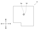
- the busbar unit 70 extends from the power module 22 to the motor 14. As shown in FIG. 7, the busbar unit 70 includes three busbars 72, 74, 76 and a cover 78.
- the busbars 72, 74, 76 are made of the same conductive material as the busbars 62, 64. Each of the busbars 72, 74, 76 extends in the left-right direction from the front of the power module 22 to the front and above the motor 14.
- the busbars 72, 74, 76 correspond to each phase of the three-phase AC.
- the busbars 72, 74, 76 conduct electricity between the power module 22 and the motor 14.
- the busbar 72 includes an end 72c that electrically contacts the power module 22, an end 72b that electrically contacts the motor 14, and a main body portion 72a between the ends 72b and 72c.
- Bus bars 74 and 76 like bus bar 72, have ends 74b and 76b, ends 74c and 76c, and body portions 74a and 76a.
- Ends 72b, 74b, 76b are electrically connected to the stator 14d of the motor 14. Ends 72c, 74c, 76c are electrically connected to the power module 22.
- the main body portions 72a, 74a, 76a are covered by a cover 78.
- the cover 78 is attached to the inner wall of the casing 12.
- the cover 78 is made of the same insulating material as the cover 66.
- the cover 78 includes a covering portion 78a and a flow path forming portion 78b.
- the covering portion 78a holds the bus bars 72, 74, 76 by covering the main body portions 72a, 74a, 76a.
- the covering portion 78a insulates the main body portions 72a, 74a, 76a from the outside of the bus bars 72, 74, 76.
- the covering portion 78a extends linearly in the left-right direction, similar to the main body portions 72a, 74a, 76a arranged in front of the inverter 20.
- the covering portion 78a has a rectangular prism shape.
- a flow path forming portion 78b is attached to the end of the covering portion 78a on the motor 14 side.
- the flow path forming portion 78b is formed integrally with the covering portion 78a.
- the flow path forming portion 78b has a flat shape extending from the end of the covering portion 78a to between the inverter 20 and the motor 14.
- the flow path forming portion 78b has an internal space indicated by a dashed line.
- the internal space of the flow path forming portion 78b is a flow path 78c through which the refrigerant flows.
- the flow path 78c extends from the end of the covering portion 78a to between the inverter 20 and the motor 14.
- the bus bars 72, 74, and 76 penetrate the internal space of the flow path forming portion 78b.
- the flow path forming portion 78b includes a partition wall 78d that surrounds the bus bars 72, 74, and 76 that penetrate the internal space.
- the bus bars 72, 74, and 76 are insulated from the flow path 78c by the partition wall 78d.
- the flow passage 78c communicates at its upper end with an inlet 78e formed in the flow passage forming portion 78b.
- the inlet 78e is provided in a cylindrical portion 78f arranged at the upper end of the flow passage forming portion 78b.
- the cylindrical portion 78f extends from the flow passage forming portion 78b in the left-right direction toward the inverter 20 side and is bent upward at the middle position.
- the cylindrical portion 78f protrudes upward from the upper surface 12a of the casing 12.
- the cylindrical portion 78f is arranged above the front end of the casing 12 and forward of the uppermost end.
- the flow passage 78c communicates below the inlet 78e with an outlet 78g formed in the flow passage forming portion 78b.
- the outlet 78g is provided in a cylindrical portion 78h arranged in the flow passage forming portion 78b.
- the cylindrical portion 78h extends from the flow passage forming portion 78b in the left-right direction toward the inverter 20 side.
- the cylindrical portion 78h is connected to the cylindrical portion 66h via a connecting pipe (not shown).
- the flow path 78c is connected from the inlet 66g to the flow path 66d via the outlet 78g.
- a cooling unit 80 is disposed above the drive device 10.
- the electric vehicle 2 is equipped with one or more cooling circuits 110 for cooling the motor 14 and the inverter 20.
- the flow of the refrigerant is indicated by thick arrows.
- FIG. 9 shows a power supply sequence 120 indicating the order of power supply between the battery pack 6 and the motor 14 via the inverter 20.
- the cooling unit 80 cools the power module 22 by the refrigerant flowing through the one or more cooling circuits 110.
- the cooling unit 80 is disposed above the power module 22.
- the refrigerant is a coolant liquid (i.e., LLC) that cools one or more devices mounted on the electric vehicle 2.
- the cooling circuit 110 includes a pipe 116 through which the refrigerant flows, a radiator 112, and a water pump 114.
- the cooling unit 80 cools the power module 22 by the refrigerant flowing through a pipe disposed around the power module 22.
- the flow paths 66d, 78c of the busbar units 60, 70 are included in a cooling circuit for cooling the inverter 20.
- the inlet 78e is connected to a pipe extending from the cooling unit 80. This causes the refrigerant from the cooling unit 80 to flow from the inlet 78e into the flow path 78c.
- the refrigerant flows downward from the inlet 78e and reaches the outlet 78g.
- the refrigerant flowing through the flow path 78c exchanges heat with the main body portions 72a, 74a, 76a of the busbars 72, 74, 76, thereby cooling the busbars 72, 74, 76.
- the refrigerant flowing out from outlet 78g flows into flow path 66d from inlet 66g.
- flow path 66d the refrigerant flows downward from inlet 66g and reaches outlet 66j.
- the refrigerant flowing through flow path 66d exchanges heat with busbars 62, 64 by flowing along main body portions 62a, 64a of busbars 62, 64. This cools busbars 62, 64.
- the refrigerant flowing out from outlet 66j flows into the piping of cooling unit 80 from communicating tube 12c.
- the busbar unit 60 allows the coolant to flow along the main body portions 62a, 64a of the busbars 62, 64. This allows the heat of the busbars 62, 64 to be efficiently released to the coolant. Similarly, the busbar unit 70 allows the heat of the busbars 72, 74, 76 to be efficiently released to the coolant.
- the refrigerant flow path 66d can be arranged integrally with the cover 66 that holds the busbars 62, 64. This eliminates the need to arrange the refrigerant flow path separately. The same applies to the busbar unit 70.
- the inlet 66g is located at the upper end of the flow path 66d, and the outlet 66j is located at the lower end of the flow path 66d.
- This configuration allows the refrigerant in the flow path 66d to flow smoothly from top to bottom. The same is true for the busbar unit 70.
- the inlet 78e of the busbar unit 70 protrudes upward from the top surface 12a of the casing 12. This makes it easier to connect the inlet 78e to the piping of the cooling unit 80 that is arranged above the drive unit 10.
- the cylindrical portion 78f that constitutes the inlet 78e is arranged above the front end of the casing 12 and forward of the top end. With this configuration, the space above the drive unit 10 can be utilized.
- the cover 66 is disposed in the gap formed between the inverter 20 and the motor 14.
- the cover 66 is curved along the rotational direction of the shaft gear 32.
- the busbars 62, 64 are curved following the shape of the cover 66.
- the cover 66 has a shape that follows the shape of the motor 14. This allows the busbar unit 60 to be disposed around the shaft gear 32. Also, as shown in FIG. 5, the busbar unit 60 overlaps with the motor 14 almost entirely in the direction of the central axis X. This allows the drive device 10 to be made smaller. This allows the space in the electric vehicle 2 to be used effectively.
- the bottom surface 12b is inclined upward from the front to the rear. With this configuration, a space can be formed below the bottom surface 12b. This makes it possible to secure space for arranging the components of the electric vehicle 2.
- the connector 28 between the battery pack 6 and the inverter 20 can be arranged below the bottom surface 12b.
- the battery pack 6 is arranged below the floor panel of the electric vehicle 2. With this configuration, the connector 28 can be arranged close to the battery pack 6. This makes it possible to shorten the power cable 7. The arrangement space for the power cable 7 can be reduced. Note that at least a portion of the battery pack 6 may be located below the drive unit 10.
- the noise filter 26, smoothing capacitor 24, and power module 22 are arranged in this order from bottom to top in the inverter 20, so that the noise filter 26 can be arranged closer to the connector 28. This makes it possible to shorten the wiring of the bus bars and the like when supplying power from the connector 28 to the noise filter 26, smoothing capacitor 24, and power module 22 in that order.
- the power module 22, smoothing capacitor 24, and noise filter 26 overlap the motor 14 in the direction of the central axis X of the motor shaft 14b.
- the inverter 20 can be placed in the space around the motor shaft 14b that is generated by the difference in size between the motor 14 and the shaft gear 32, i.e., the difference in diameter. This allows the space generated by the difference in size between the motor 14 and the shaft gear 32 to be used effectively.
- the integration rate of the inverter 20 can be improved and space can be used effectively, compared to a configuration in which the inverter 20 is placed together in the space above the motor 14, for example.
- the inverter 20, i.e., the power module 22, the smoothing capacitor 24, and the noise filter 26 are arranged to overlap with the shaft gear 32 in the radial direction of the shaft gear 32.
- the shaft gear 32 is arranged in the center of the power module 22, the smoothing capacitor 24, and the noise filter 26.
- the shaft gear 32 overlaps with at least one of the power module 22, the smoothing capacitor 24, and the noise filter 26 in the radial direction of the shaft gear 32 over the entire length in the direction of the central axis X. This allows the power module 22, the smoothing capacitor 24, and the noise filter 26 to be arranged in the space around the shaft gear 32 formed by the dimensional difference between the motor 14 and the shaft gear 32.
- At least a portion of the inverter 20, i.e., any one of the power module 22, the smoothing capacitor 24, and the noise filter 26, may be arranged to overlap with the shaft gear 32 in the radial direction of the shaft gear 32.
- at least a portion of the shaft gear 32 in the direction of the central axis X may not overlap with any of the power module 22, the smoothing capacitor 24, and the noise filter 26 in the radial direction of the shaft gear 32.
- the power module 22, smoothing capacitor 24, and noise filter 26 are arranged separately, making it possible to effectively utilize the curved space around the shaft gear 32.
- the maximum length along the rotation direction R of the shaft gear 32 is longer than the maximum length along the radial direction of the shaft gear 32.
- the smoothing capacitor 24 the maximum length along the rotation direction of the shaft gear 32 is longer than the maximum length along the radial direction of the shaft gear 32.
- the noise filter 26 the maximum length along the rotation direction of the shaft gear 32 is longer than the maximum length along the radial direction of the shaft gear 32.
- the power module 22, the smoothing capacitor 24, and the noise filter 26 are each arranged such that the longitudinal direction is aligned with the rotation direction of the shaft gear 32 and the lateral direction is aligned with the radial direction of the shaft gear 32. This makes it possible to effectively utilize the space around the shaft gear 32 while preventing the inverter 20 from expanding in the radial direction of the shaft gear 32.
- the angle AN from the end 22b of the power module 22 opposite the smoothing capacitor 24 to the end 26b of the noise filter 26 opposite the smoothing capacitor 24 with respect to the central axis X is 240 degrees or more. It is preferable that the angle AN be 180 degrees or more. With this configuration, the space around the shaft gear 32 can be effectively utilized.
- the power module 22 and the counter gear 34 are arranged with the shaft gear 32 in between.
- the counter gear 34 has a larger diameter than the shaft gear 32 to achieve the deceleration function of the motor 14.
- the power module 22 is also the largest among the components of the inverter 20. By arranging the power module 22 and the counter gear 34, which are large in size, with the shaft gear 32 in between, the power module 22 and the counter gear 34 can be arranged without interfering with each other.
- the shaft gear 32 has the smallest diameter among the multiple gears included in the gear unit 30.
- the external dimensions of the drive unit 10 can be kept small compared to a configuration in which the power module 22, the smoothing capacitor 24, and the noise filter 26 are arranged around the gears other than the shaft gear 32 among the multiple gears included in the gear unit 30.
- the shaft gear 32 is an example of a "first gear.”
- the counter gear 34 is an example of a "second gear.”
- the drive unit 10 may be disposed at the rear end of the vehicle.
- the underside 12b of the drive unit 10 may be inclined upward toward the center C in the fore-and-aft direction of the electric vehicle 2, i.e., toward the front of the electric vehicle 2.
- the connector 28 may be disposed below the front end of the drive unit 10 and forward of the lowest end.
- the inlet 78e may be disposed above the rear end and rearward of the highest end.
- the power module 22, the smoothing capacitor 24, and the noise filter 26 are arranged side by side along the rotation direction R.
- at least two of the power module 22, the smoothing capacitor 24, and the noise filter 26 may be arranged side by side in the radial direction of the shaft gear 32.
- at least two of the power module 22, the smoothing capacitor 24, and the noise filter 26 may be arranged side by side in the axial direction of the central axis X, i.e., in the left-right direction.
- the power module 22, the smoothing capacitor 24, and the noise filter 26 may be arranged together above the shaft gear 32.
- gear unit 30 There is no limit to the number of gears arranged in the gear unit 30.
- the rotation of the motor 14 is decelerated in two stages.
- the rotation of the motor 14 may be decelerated in three stages.
- at least eight gears may be arranged in the gear unit 30.
- the shaft gear 32 may have the smallest diameter of the multiple gears included in the gear unit 30.
- the refrigerant flow path may not be located in the cover 66, 78. In this case, the refrigerant flow path may be located in a position different from the cover 66, 78.
- the busbar unit 60 does not have to be curved along the rotation direction R.
- the busbar unit 60 may be formed in a straight line.
- At least one of the busbar units 60, 70 may be used in electrical equipment other than the electric vehicle 2. In particular, it may be used in a busbar that is used in at least one of high current and high temperature environments.
Landscapes
- Engineering & Computer Science (AREA)
- Power Engineering (AREA)
- Chemical & Material Sciences (AREA)
- Combustion & Propulsion (AREA)
- Transportation (AREA)
- Mechanical Engineering (AREA)
- Microelectronics & Electronic Packaging (AREA)
- Connection Of Motors, Electrical Generators, Mechanical Devices, And The Like (AREA)
- Inverter Devices (AREA)
Priority Applications (3)
| Application Number | Priority Date | Filing Date | Title |
|---|---|---|---|
| CN202480020237.8A CN120982002A (zh) | 2023-03-22 | 2024-02-22 | 驱动装置 |
| EP24774572.2A EP4686052A1 (en) | 2023-03-22 | 2024-02-22 | Drive device |
| KR1020257034860A KR20250163956A (ko) | 2023-03-22 | 2024-02-22 | 구동 장치 |
Applications Claiming Priority (2)
| Application Number | Priority Date | Filing Date | Title |
|---|---|---|---|
| JP2023-045413 | 2023-03-22 | ||
| JP2023045413A JP2024134947A (ja) | 2023-03-22 | 2023-03-22 | 駆動装置 |
Publications (1)
| Publication Number | Publication Date |
|---|---|
| WO2024195427A1 true WO2024195427A1 (ja) | 2024-09-26 |
Family
ID=92841762
Family Applications (1)
| Application Number | Title | Priority Date | Filing Date |
|---|---|---|---|
| PCT/JP2024/006448 Ceased WO2024195427A1 (ja) | 2023-03-22 | 2024-02-22 | 駆動装置 |
Country Status (5)
| Country | Link |
|---|---|
| EP (1) | EP4686052A1 (https=) |
| JP (1) | JP2024134947A (https=) |
| KR (1) | KR20250163956A (https=) |
| CN (1) | CN120982002A (https=) |
| WO (1) | WO2024195427A1 (https=) |
Cited By (1)
| Publication number | Priority date | Publication date | Assignee | Title |
|---|---|---|---|---|
| US20250055355A1 (en) * | 2023-08-07 | 2025-02-13 | c/o Garrett Transportation I Inc. | Bracket for coupling a power electronic device and a compressor assembly |
Citations (4)
| Publication number | Priority date | Publication date | Assignee | Title |
|---|---|---|---|---|
| JP2019193440A (ja) * | 2018-04-25 | 2019-10-31 | アイシン・エィ・ダブリュ株式会社 | 車両用駆動装置 |
| JP2020040578A (ja) | 2018-09-12 | 2020-03-19 | 本田技研工業株式会社 | 車両 |
| JP2020092503A (ja) * | 2018-12-04 | 2020-06-11 | トヨタ自動車株式会社 | 車両用駆動装置 |
| JP2021112116A (ja) * | 2020-01-10 | 2021-08-02 | アイシン・エィ・ダブリュ株式会社 | 車両用駆動装置 |
-
2023
- 2023-03-22 JP JP2023045413A patent/JP2024134947A/ja active Pending
-
2024
- 2024-02-22 WO PCT/JP2024/006448 patent/WO2024195427A1/ja not_active Ceased
- 2024-02-22 CN CN202480020237.8A patent/CN120982002A/zh active Pending
- 2024-02-22 EP EP24774572.2A patent/EP4686052A1/en active Pending
- 2024-02-22 KR KR1020257034860A patent/KR20250163956A/ko active Pending
Patent Citations (4)
| Publication number | Priority date | Publication date | Assignee | Title |
|---|---|---|---|---|
| JP2019193440A (ja) * | 2018-04-25 | 2019-10-31 | アイシン・エィ・ダブリュ株式会社 | 車両用駆動装置 |
| JP2020040578A (ja) | 2018-09-12 | 2020-03-19 | 本田技研工業株式会社 | 車両 |
| JP2020092503A (ja) * | 2018-12-04 | 2020-06-11 | トヨタ自動車株式会社 | 車両用駆動装置 |
| JP2021112116A (ja) * | 2020-01-10 | 2021-08-02 | アイシン・エィ・ダブリュ株式会社 | 車両用駆動装置 |
Cited By (1)
| Publication number | Priority date | Publication date | Assignee | Title |
|---|---|---|---|---|
| US20250055355A1 (en) * | 2023-08-07 | 2025-02-13 | c/o Garrett Transportation I Inc. | Bracket for coupling a power electronic device and a compressor assembly |
Also Published As
| Publication number | Publication date |
|---|---|
| KR20250163956A (ko) | 2025-11-21 |
| CN120982002A (zh) | 2025-11-18 |
| EP4686052A1 (en) | 2026-01-28 |
| JP2024134947A (ja) | 2024-10-04 |
Similar Documents
| Publication | Publication Date | Title |
|---|---|---|
| CN105102252B (zh) | 车辆用驱动装置 | |
| JP4645602B2 (ja) | 車両の駆動装置 | |
| JP7435728B2 (ja) | 車両用駆動装置 | |
| WO2009122597A1 (ja) | 駆動装置 | |
| JP2016092931A (ja) | 駆動装置及びそれを備える乗り物 | |
| JP2016092932A (ja) | 駆動装置及びそれを備える乗り物 | |
| JP2022107381A (ja) | 電力変換装置 | |
| EP4175157B1 (en) | Inverter structure | |
| EP4175158B1 (en) | Inverter structure | |
| EP4245584B1 (en) | Vehicular drive device | |
| CN109560670A (zh) | 一种新能源车用水冷电机系统 | |
| WO2024195427A1 (ja) | 駆動装置 | |
| JP2018046745A (ja) | 駆動装置及びそれを備える乗り物 | |
| EP4434783A1 (en) | Electric-powered vehicle | |
| JP2024134944A (ja) | バスバーユニット | |
| JP7816204B2 (ja) | 駆動装置 | |
| EP4175156B1 (en) | Inverter structure | |
| US11850953B2 (en) | Vehicle drive unit | |
| JP2024051566A (ja) | 駆動装置 | |
| JP2025079625A (ja) | 車両用駆動装置 |
Legal Events
| Date | Code | Title | Description |
|---|---|---|---|
| 121 | Ep: the epo has been informed by wipo that ep was designated in this application |
Ref document number: 24774572 Country of ref document: EP Kind code of ref document: A1 |
|
| WWE | Wipo information: entry into national phase |
Ref document number: 2501006215 Country of ref document: TH |
|
| WWE | Wipo information: entry into national phase |
Ref document number: CN2024800202378 Country of ref document: CN |
|
| REG | Reference to national code |
Ref country code: BR Ref legal event code: B01A Ref document number: 112025020077 Country of ref document: BR |
|
| ENP | Entry into the national phase |
Ref document number: 1020257034860 Country of ref document: KR Free format text: ST27 STATUS EVENT CODE: A-0-1-A10-A15-NAP-PA0105 (AS PROVIDED BY THE NATIONAL OFFICE) |
|
| WWE | Wipo information: entry into national phase |
Ref document number: KR1020257034860 Country of ref document: KR Ref document number: 1020257034860 Country of ref document: KR Ref document number: 202517100656 Country of ref document: IN |
|
| WWE | Wipo information: entry into national phase |
Ref document number: 2024774572 Country of ref document: EP |
|
| NENP | Non-entry into the national phase |
Ref country code: DE |
|
| ENP | Entry into the national phase |
Ref document number: 2024774572 Country of ref document: EP Effective date: 20251022 |
|
| ENP | Entry into the national phase |
Ref document number: 2024774572 Country of ref document: EP Effective date: 20251022 |
|
| ENP | Entry into the national phase |
Ref document number: 2024774572 Country of ref document: EP Effective date: 20251022 |
|
| WWP | Wipo information: published in national office |
Ref document number: 202517100656 Country of ref document: IN |
|
| ENP | Entry into the national phase |
Ref document number: 2024774572 Country of ref document: EP Effective date: 20251022 |
|
| ENP | Entry into the national phase |
Ref document number: 2024774572 Country of ref document: EP Effective date: 20251022 |
|
| ENP | Entry into the national phase |
Ref document number: 2024774572 Country of ref document: EP Effective date: 20251022 |