WO2024194990A1 - 加工情報表示装置 - Google Patents
加工情報表示装置 Download PDFInfo
- Publication number
- WO2024194990A1 WO2024194990A1 PCT/JP2023/010919 JP2023010919W WO2024194990A1 WO 2024194990 A1 WO2024194990 A1 WO 2024194990A1 JP 2023010919 W JP2023010919 W JP 2023010919W WO 2024194990 A1 WO2024194990 A1 WO 2024194990A1
- Authority
- WO
- WIPO (PCT)
- Prior art keywords
- machining
- block number
- block
- selected position
- display device
- Prior art date
- Legal status (The legal status is an assumption and is not a legal conclusion. Google has not performed a legal analysis and makes no representation as to the accuracy of the status listed.)
- Ceased
Links
Images






Classifications
-
- G—PHYSICS
- G05—CONTROLLING; REGULATING
- G05B—CONTROL OR REGULATING SYSTEMS IN GENERAL; FUNCTIONAL ELEMENTS OF SUCH SYSTEMS; MONITORING OR TESTING ARRANGEMENTS FOR SUCH SYSTEMS OR ELEMENTS
- G05B19/00—Program-control systems
- G05B19/02—Program-control systems electric
- G05B19/18—Numerical control [NC], i.e. automatically operating machines, in particular machine tools, e.g. in a manufacturing environment, so as to execute positioning, movement or co-ordinated operations by means of program data in numerical form
- G05B19/409—Numerical control [NC], i.e. automatically operating machines, in particular machine tools, e.g. in a manufacturing environment, so as to execute positioning, movement or co-ordinated operations by means of program data in numerical form characterised by using manual data input [MDI] or by using control panel, e.g. controlling functions with the panel; characterised by control panel details or by setting parameters
Definitions
- This disclosure relates to a processing information display device.
- a machining information display device that includes a display control unit that analyzes a machining program for a machine tool and displays a machining path in the machining program on a display device, a block information acquisition unit that acquires block information for each block in the machining program, a selection position acquisition unit that accepts a selection of an arbitrary position on the machining path displayed on the display device and acquires a selected position on the machining path for which a selection has been accepted, a selection coordinate identification unit that identifies the coordinates of the selected position based on the block information, and a progression direction determination unit that determines the direction of progression of machining on the machining path based on the coordinates of the selected position, the coordinates of the current position on the machining path, and the block information.
- FIG. 13 is a diagram showing the relationship between a current position and a selected position on a machining path.
- FIG. 13 is a diagram showing an example of a machining path displayed on a display unit during forward movement.
- FIG. 13 is a diagram showing an example of a machining path displayed on a display unit during forward movement.
- 13A and 13B are diagrams showing an example of a machining path displayed on the display unit during reverse movement;
- 13A and 13B are diagrams showing an example of a machining path displayed on the display unit during reverse movement;
- 13A and 13B are diagrams showing an example of a machining path displayed on the display unit during reverse movement;
- FIG. 13 is a diagram showing an example of a machining path displayed on a display unit during forward movement.
- Figure 1 is a block diagram showing the configuration of a processing information display device 1 according to one embodiment of the present disclosure.
- the machining information display device 1 is a machining information display device that displays information on the machining of a workpiece.
- the machining information display device 1 can be realized by executing an appropriate control program on one or more computer devices having a memory, a processor, an input/output interface, etc.
- the machining information display device 1 may be a numerical control device that controls a machine tool, a machining simulator that simulates the operation of a machine tool, a management computer that manages multiple machine tools, etc. to which the functions described below have been added.
- the machine tool may be, for example, a processing machine having multiple drive axes.
- the processing information display device 1 includes a control unit 11, a storage unit 12, a display unit 13, and an operation unit 14.
- the control unit 11 is composed of one or more processors such as a CPU (Central Processing Unit), and realizes various functions by executing programs stored in the storage unit 12.
- the control unit 11 also includes a display control unit 111, a block information acquisition unit 112, a selected position acquisition unit 113, a selected coordinate identification unit 114, and a traveling direction determination unit 115.
- the memory unit 12 is composed of storage devices such as a ROM (Read Only Memory), a RAM (Random Access Memory), a HDD (Hard Disk Drive), or a SSD (Solid State Drive), and stores various information.
- the memory unit 12 is provided within the processing information display device 1, but the memory unit 12 may be provided in an external electronic device or an external server, etc., outside the processing information display device 1.
- the display unit 13 displays various information based on signals transmitted from the control unit 11.
- the display unit 13 is composed of, for example, an LCD (Liquid Crystal Display), an organic EL (organic electroluminescence), a CRT (Cathode Ray Tube), etc.
- the display unit 13 is provided within the processing information display device 1, but the display unit 13 may be an external electronic device connected to the processing information display device 1, an external display device, etc.
- the operation unit 14 is composed of buttons, keys, switches, a keyboard, a mouse, a teach pendant, etc., and accepts various input operations from the user.
- the display unit 13 and the operation unit 14 may be a teach pendant having an integrated touch panel, etc.
- the teach pendant may also be composed of a tablet terminal.
- the display control unit 111 reads out a machining program for a machine tool from the storage unit 12, analyzes the machining program, and displays the machining path in the machining program on the display unit 13.
- the machining program is composed of one or more blocks.
- the block information acquisition unit 112 acquires block information for each block in the analyzed machining program.
- the block information includes at least the block number, start point, and end point of each block.
- the selected position acquisition unit 113 accepts a selection of an arbitrary position on the processing path displayed on the display unit 13, and acquires the selected position on the processing path for which the selection has been accepted.
- the selection of an arbitrary position may be performed, for example, by the user operating the operation unit 14, or, if the display unit 13 and the operation unit 14 are an integrated touch panel, may be performed by a touch operation on the touch panel.
- the selection coordinate identification unit 114 identifies the coordinates of the selection position based on the block information acquired by the block information acquisition unit 112.
- the proceeding direction determination unit 115 determines the proceeding direction of the machining on the machining path based on the coordinates of the selected position identified by the selected coordinate identification unit 114, the coordinates of the current position on the machining path, and the block information acquired by the block information acquisition unit 112.
- the direction of travel determination unit 115 determines the direction of travel of the machining along the machining path based on the current direction of travel of the machining along the machining path, the block number of the block corresponding to the selected position, the block number of the block corresponding to the current position, a first distance from the start point of the block corresponding to the selected position to the selected position, and a second distance from the start point to the current position.
- FIG. 2 is a diagram showing the relationship between the current position on the processing path and the selected position.
- the selected position acquisition unit 113 accepts a selection of an arbitrary position on the processing path L displayed on the display unit 13, and acquires the selected position M3 on the processing path L that has accepted the selection.
- the proceeding direction determination unit 115 determines the proceeding direction of the machining on the machining path based on the coordinates of the selected position M3, the coordinates of the current position M2, and the acquired block information. Specifically, the proceeding direction determination unit 115 calculates a first distance Dsl from the start point of the block corresponding to the selected position to the coordinates of the selected position.
- the first distance Dsl is calculated using the following formula:
- the traveling direction determination unit 115 calculates a second distance Dcr from the starting point M1 to the current position M2.
- the second distance D cr is calculated using the following formula:
- the coordinate vector P cr is the coordinate vector of the current position M2, and is calculated using the following formula.
- Coordinate vector P cr (coordinates of each axis at current position M2) - (coordinates of each axis at origin O)
- the direction of travel determination unit 115 determines the direction of travel of the machining along the machining path using the following conditions:
- the proceeding direction determination unit 115 determines the proceeding direction to be the reverse direction when the block number of the selected position is smaller than the block number of the current position while processing is proceeding in the forward direction (forward), or when the block number of the selected position is equal to the block number of the current position and the first distance Dsl is smaller than the second distance Dcr .
- the proceeding direction determination unit 115 determines the proceeding direction to be the forward direction.
- the proceeding direction determination unit 115 determines the proceeding direction to be the reverse direction.
- the proceeding direction determination unit 115 determines the proceeding direction to be the forward direction when the block number of the selected position is greater than the block number of the current position, or when the block number of the selected position is equal to the block number of the current position and the first distance Dsl is greater than or equal to the second distance Dcr .
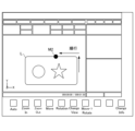
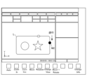
- FIGS. 3A to 3C are diagrams showing examples of the machining path displayed on the display unit 13 during forward and reverse cutting.
- the examples shown in FIGS. 3A to 3C and 4A to 4C are examples of the machining path L when cutting a thin plate.
- machining is proceeding in the forward direction on machining path L, and a current position M2 is shown.
- a selected position M3 is selected on machining path L, and the selected position acquisition unit 113 acquires the selected position M3 on the machining path L that has accepted the selection.
- the selected coordinate identification unit 114 identifies the coordinates of the selected position M3.
- the proceeding direction determination unit 115 determines the proceeding direction of the machining on the machining path L to be the reverse direction based on the coordinates of the selected position M3, the coordinates of the current position M2 on the machining path L, and the acquired block information.
- the proceeding direction of the machining is determined to be the reverse direction, the machining on the machining path L proceeds in the reverse direction, and the current position M2 moves in the reverse direction.
- FIGS. 4A to 4C are diagrams showing examples of the machining path displayed on the display unit 13 during reverse and forward movement.
- machining is proceeding in the reverse direction on machining path L, and the current position M2 is shown.
- a selection position M3 is selected on the processing path L, and the selection position acquisition unit 113 acquires the selection position M3 on the processing path L that has accepted the selection. Then, as described above, the selection coordinate identification unit 114 identifies the coordinates of the selection position M3.
- the proceeding direction determination unit 115 determines the processing proceeding direction in the processing path L to be the forward direction based on the coordinates of the selected position M3, the coordinates of the current position M2 in the processing path L, and the acquired block information.
- the processing proceeding direction is determined to be the forward direction, processing proceeds in the forward direction in the processing path L, and the current position M2 moves in the forward direction.
- the machining information display device 1 includes a display control unit 111 that reads out a machining program for a machine tool from the storage unit 12, analyzes the machining program, and displays the machining path in the machining program on the display unit 13; a block information acquisition unit 112 that acquires block information for each block in the analyzed machining program; a selection position acquisition unit 113 that accepts a selection of an arbitrary position in the machining path displayed on the display unit 13 and acquires the selected position in the machining path for which the selection has been accepted; a selection coordinate identification unit 114 that identifies the coordinates of the selected position based on the block information acquired by the block information acquisition unit 112; and a progression direction determination unit 115 that determines the progression direction of machining on the machining path based on the coordinates of the selected position selected by the selection coordinate identification unit 114, the coordinates of the current position on the machining path, and the block information acquired by the block information acquisition unit 112.
- the machining information display device 1 can indicate the location on the machining path to which the user wishes to reverse, and therefore can easily match the location to which the user wishes to reverse with the position on the workpiece. Furthermore, in conventional technology, in order to automatically switch from reverse to forward or from forward to reverse, it was necessary to perform complex sequence control using, for example, a ladder program.
- the machining information display device 1 according to this embodiment does not require complex sequence control to switch from reverse to forward or from forward to reverse, and can easily perform automatic switching from reverse to forward or from forward to reverse.
- the block information also includes at least the block number, start point, and end point of each block. This allows the processing information display device 1 to identify the coordinates of the selected position using the block information corresponding to the selected position and determine the processing direction.
- the direction of progress determination unit 115 also determines the direction of progress of processing on the processing path based on the current processing direction on the processing path, the block number of the block corresponding to the selected position, the block number of the block corresponding to the current position, a first distance from the start point of the block corresponding to the selected position to the selected position, and a second distance from the start point to the current position. This allows the processing information display device 1 to determine the processing direction as forward or backward depending on the selected position on the processing path.
- the direction of progress determination unit 115 also uses the above-mentioned conditions A to D to determine whether the direction of progress of the processing on the processing path is forward or backward. This allows the processing information display device 1 to determine an appropriate direction of progress of processing according to the current position, selected position, and block information.
- the processing information display device 1 has been exemplified by the display unit 13 as a display device for displaying the processing path, but instead, the processing path may be displayed by other methods.
- the processing information display device 1 may use projection mapping to project an image of the processing path onto the workpiece that is actually being processed.
- the processing information display device 1 may include a projector or the like as a display device for projecting the image of the processing path.
- the processing information display device 1 may use augmented reality to superimpose an image of the processing path on a captured image of the workpiece that is actually being processed.
- the processing information display device 1 may include an imaging device that acquires a captured image of the workpiece that is actually being processed, a control device that performs a process of superimposing the captured image and an image of the processing path, and a display device that displays an image in which the captured image and the image of the processing path are superimposed.
- processing information display device 1 can be realized by hardware, software, or a combination of these.
- control method performed by the processing information display device 1 can also be realized by hardware, software, or a combination of these.
- being realized by software means being realized by a computer reading and executing a program.
- Non-transitory computer readable media include various types of tangible storage media.
- Examples of non-transitory computer readable media include magnetic recording media (e.g., hard disk drives), magneto-optical recording media (e.g., magneto-optical disks), CD-ROMs (Read Only Memory), CD-Rs, CD-R/Ws, and semiconductor memories (e.g., mask ROMs, PROMs (Programmable ROMs), EPROMs (Erasable PROMs), flash ROMs, and RAMs (random access memory)).
- a display control unit (111) that analyzes a machining program for a machine tool and displays a machining path in the machining program on a display device (13);
- a block information acquisition unit (112) that acquires block information of each block in the processing program;
- a selection position acquisition unit (113) that accepts a selection of an arbitrary position on the processing path displayed on the display device (13) and acquires the selected position on the processing path that has been selected;
- a selection coordinate specification unit (114) that specifies coordinates of the selection position based on the block information;
- a progression direction determination unit (115) that determines a progression direction of machining on the machining path based on the coordinates of the selected position, the coordinates of a current position on the machining path, and the block information;
- Appendix 2 The processing information display device (1) according to appendix 1, wherein the block information includes at least a block number, a start point, and an end point of each block.
- Appendix 3 The processing information display device (1) described in Appendix 1 or 2, wherein the progress direction determination unit (115) determines the processing progress direction in the processing path based on the current processing progress direction in the processing path, the block number of the block corresponding to the selected position, the block number of the block corresponding to the current position, a first distance from a start point of the block corresponding to the selected position to the selected position, and a second distance from the start point to the current position.
- the traveling direction determination unit (Appendix 4) When the processing is proceeding in a forward direction, if the block number of the selected position is smaller than the block number of the current position, or if the block number of the selected position is equal to the block number of the current position and the first distance is smaller than the second distance, the proceeding direction is determined to be a reverse direction; When the processing is proceeding in a forward direction, if the block number of the selected position is greater than the block number of the current position, or if the block number of the selected position is equal to the block number of the current position and the first distance is equal to or greater than the second distance, the proceeding direction is determined to be a forward direction; When the machining is proceeding in the reverse direction, if the block number of the selected position is smaller than the block number of the current position, or if the block number of the selected position is equal to the block number of the current position and the first distance is smaller than the second distance, determining the proceeding direction as the reverse direction; When the machining is proceeding in the reverse direction, if the block number of the
Landscapes
- Engineering & Computer Science (AREA)
- Human Computer Interaction (AREA)
- Manufacturing & Machinery (AREA)
- Physics & Mathematics (AREA)
- General Physics & Mathematics (AREA)
- Automation & Control Theory (AREA)
- Numerical Control (AREA)
Priority Applications (2)
| Application Number | Priority Date | Filing Date | Title |
|---|---|---|---|
| PCT/JP2023/010919 WO2024194990A1 (ja) | 2023-03-20 | 2023-03-20 | 加工情報表示装置 |
| JP2025507963A JPWO2024194990A1 (https=) | 2023-03-20 | 2023-03-20 |
Applications Claiming Priority (1)
| Application Number | Priority Date | Filing Date | Title |
|---|---|---|---|
| PCT/JP2023/010919 WO2024194990A1 (ja) | 2023-03-20 | 2023-03-20 | 加工情報表示装置 |
Publications (1)
| Publication Number | Publication Date |
|---|---|
| WO2024194990A1 true WO2024194990A1 (ja) | 2024-09-26 |
Family
ID=92841133
Family Applications (1)
| Application Number | Title | Priority Date | Filing Date |
|---|---|---|---|
| PCT/JP2023/010919 Ceased WO2024194990A1 (ja) | 2023-03-20 | 2023-03-20 | 加工情報表示装置 |
Country Status (2)
| Country | Link |
|---|---|
| JP (1) | JPWO2024194990A1 (https=) |
| WO (1) | WO2024194990A1 (https=) |
Citations (6)
| Publication number | Priority date | Publication date | Assignee | Title |
|---|---|---|---|---|
| WO2018158795A1 (ja) * | 2017-02-28 | 2018-09-07 | 三菱電機株式会社 | 数値制御装置 |
| JP2019101799A (ja) * | 2017-12-04 | 2019-06-24 | Dmg森精機株式会社 | 加工プログラム解析装置およびこれを備えた工作機械、ならびに加工プログラム解析プログラムおよび加工プログラム解析方法 |
| JP2021043771A (ja) * | 2019-09-12 | 2021-03-18 | Dmg森精機株式会社 | 情報処理装置 |
| JP2021068180A (ja) * | 2019-10-23 | 2021-04-30 | ファナック株式会社 | 最適化処理装置 |
| JP2021086194A (ja) * | 2019-11-25 | 2021-06-03 | ファナック株式会社 | プログラム再開支援装置 |
| JP2021105825A (ja) * | 2019-12-26 | 2021-07-26 | ファナック株式会社 | シミュレーション装置、数値制御装置、及びシミュレーション方法 |
-
2023
- 2023-03-20 WO PCT/JP2023/010919 patent/WO2024194990A1/ja not_active Ceased
- 2023-03-20 JP JP2025507963A patent/JPWO2024194990A1/ja active Pending
Patent Citations (6)
| Publication number | Priority date | Publication date | Assignee | Title |
|---|---|---|---|---|
| WO2018158795A1 (ja) * | 2017-02-28 | 2018-09-07 | 三菱電機株式会社 | 数値制御装置 |
| JP2019101799A (ja) * | 2017-12-04 | 2019-06-24 | Dmg森精機株式会社 | 加工プログラム解析装置およびこれを備えた工作機械、ならびに加工プログラム解析プログラムおよび加工プログラム解析方法 |
| JP2021043771A (ja) * | 2019-09-12 | 2021-03-18 | Dmg森精機株式会社 | 情報処理装置 |
| JP2021068180A (ja) * | 2019-10-23 | 2021-04-30 | ファナック株式会社 | 最適化処理装置 |
| JP2021086194A (ja) * | 2019-11-25 | 2021-06-03 | ファナック株式会社 | プログラム再開支援装置 |
| JP2021105825A (ja) * | 2019-12-26 | 2021-07-26 | ファナック株式会社 | シミュレーション装置、数値制御装置、及びシミュレーション方法 |
Also Published As
| Publication number | Publication date |
|---|---|
| JPWO2024194990A1 (https=) | 2024-09-26 |
Similar Documents
| Publication | Publication Date | Title |
|---|---|---|
| CN104111812A (zh) | 显示控制方法和装置 | |
| KR20120021212A (ko) | 화상표시장치 및 화상표시 방법 | |
| WO2018185972A1 (ja) | マップデータ生成装置および方法 | |
| CN101739722A (zh) | 信息处理装置和信息处理系统 | |
| JP7009882B2 (ja) | 表示プログラム、表示方法、及び表示装置 | |
| WO2024194990A1 (ja) | 加工情報表示装置 | |
| JP4041060B2 (ja) | 画像処理装置、画像処理方法 | |
| US20250124558A1 (en) | Information processing apparatus, information processing method, and non-transitory computer-readable storage medium | |
| JP4668059B2 (ja) | 目視検査支援装置、目視検査支援プログラムおよびそのプログラムを記録した記録媒体 | |
| JP6233034B2 (ja) | 基板解析プログラム、情報処理装置及び基板解析方法 | |
| EP4475547A1 (en) | Program, information processing device, and information processing method | |
| JP2007178129A5 (https=) | ||
| JP2021060856A (ja) | 画像合成装置、画像合成装置の制御方法およびプログラム | |
| JP7846512B2 (ja) | 画像処理装置、画像処理方法及びプログラム | |
| JP2019082927A (ja) | 情報処理装置、情報処理方法、プログラム | |
| JP7066013B2 (ja) | 治具の配置を示す映像処理システム | |
| US20250200739A1 (en) | Information processing apparatus, information processing method, and non-transitory computer-readable medium | |
| US20250225644A1 (en) | Information processing apparatus, information processing method, and non-transitory computer-readable storage medium storing a computer program | |
| JP2005208886A (ja) | 画像補正装置および画像補正プログラム | |
| US20240354892A1 (en) | Information processing apparatus, information processing method, and storage medium for generating processed images different in resolution | |
| US20240211094A1 (en) | Image processing apparatus capable of operating three dimensional virtual object, control method therefor, and storage medium storing control program therefor | |
| JP7642186B2 (ja) | 情報処理装置、情報処理方法及び情報処理プログラム | |
| JP2025110277A (ja) | 画像処理装置、画像処理方法 | |
| JP2004239761A (ja) | 画像測定装置及びエッジ追跡測定プログラム生成用プログラム | |
| JP7644329B2 (ja) | 情報処理装置、情報処理方法、プログラム |
Legal Events
| Date | Code | Title | Description |
|---|---|---|---|
| 121 | Ep: the epo has been informed by wipo that ep was designated in this application |
Ref document number: 23928573 Country of ref document: EP Kind code of ref document: A1 |
|
| WWE | Wipo information: entry into national phase |
Ref document number: 2025507963 Country of ref document: JP |
|
| NENP | Non-entry into the national phase |
Ref country code: DE |
|
| 122 | Ep: pct application non-entry in european phase |
Ref document number: 23928573 Country of ref document: EP Kind code of ref document: A1 |