WO2024190854A1 - 電動シリンダ装置 - Google Patents
電動シリンダ装置 Download PDFInfo
- Publication number
- WO2024190854A1 WO2024190854A1 PCT/JP2024/009936 JP2024009936W WO2024190854A1 WO 2024190854 A1 WO2024190854 A1 WO 2024190854A1 JP 2024009936 W JP2024009936 W JP 2024009936W WO 2024190854 A1 WO2024190854 A1 WO 2024190854A1
- Authority
- WO
- WIPO (PCT)
- Prior art keywords
- piston
- electric motor
- cylinder
- control device
- rotation speed
- Prior art date
- Legal status (The legal status is an assumption and is not a legal conclusion. Google has not performed a legal analysis and makes no representation as to the accuracy of the status listed.)
- Ceased
Links
Images
Classifications
-
- B—PERFORMING OPERATIONS; TRANSPORTING
- B60—VEHICLES IN GENERAL
- B60T—VEHICLE BRAKE CONTROL SYSTEMS OR PARTS THEREOF; BRAKE CONTROL SYSTEMS OR PARTS THEREOF, IN GENERAL; ARRANGEMENT OF BRAKING ELEMENTS ON VEHICLES IN GENERAL; PORTABLE DEVICES FOR PREVENTING UNWANTED MOVEMENT OF VEHICLES; VEHICLE MODIFICATIONS TO FACILITATE COOLING OF BRAKES
- B60T13/00—Transmitting braking action from initiating means to ultimate brake actuator with power assistance or drive; Brake systems incorporating such transmitting means, e.g. air-pressure brake systems
- B60T13/74—Transmitting braking action from initiating means to ultimate brake actuator with power assistance or drive; Brake systems incorporating such transmitting means, e.g. air-pressure brake systems with electrical assistance or drive
- B60T13/745—Transmitting braking action from initiating means to ultimate brake actuator with power assistance or drive; Brake systems incorporating such transmitting means, e.g. air-pressure brake systems with electrical assistance or drive acting on a hydraulic system, e.g. a master cylinder
-
- B—PERFORMING OPERATIONS; TRANSPORTING
- B60—VEHICLES IN GENERAL
- B60T—VEHICLE BRAKE CONTROL SYSTEMS OR PARTS THEREOF; BRAKE CONTROL SYSTEMS OR PARTS THEREOF, IN GENERAL; ARRANGEMENT OF BRAKING ELEMENTS ON VEHICLES IN GENERAL; PORTABLE DEVICES FOR PREVENTING UNWANTED MOVEMENT OF VEHICLES; VEHICLE MODIFICATIONS TO FACILITATE COOLING OF BRAKES
- B60T13/00—Transmitting braking action from initiating means to ultimate brake actuator with power assistance or drive; Brake systems incorporating such transmitting means, e.g. air-pressure brake systems
- B60T13/10—Transmitting braking action from initiating means to ultimate brake actuator with power assistance or drive; Brake systems incorporating such transmitting means, e.g. air-pressure brake systems with fluid assistance, drive, or release
- B60T13/12—Transmitting braking action from initiating means to ultimate brake actuator with power assistance or drive; Brake systems incorporating such transmitting means, e.g. air-pressure brake systems with fluid assistance, drive, or release the fluid being liquid
- B60T13/14—Transmitting braking action from initiating means to ultimate brake actuator with power assistance or drive; Brake systems incorporating such transmitting means, e.g. air-pressure brake systems with fluid assistance, drive, or release the fluid being liquid using accumulators or reservoirs fed by pumps
- B60T13/142—Systems with master cylinder
- B60T13/145—Master cylinder integrated or hydraulically coupled with booster
- B60T13/146—Part of the system directly actuated by booster pressure
-
- B—PERFORMING OPERATIONS; TRANSPORTING
- B60—VEHICLES IN GENERAL
- B60T—VEHICLE BRAKE CONTROL SYSTEMS OR PARTS THEREOF; BRAKE CONTROL SYSTEMS OR PARTS THEREOF, IN GENERAL; ARRANGEMENT OF BRAKING ELEMENTS ON VEHICLES IN GENERAL; PORTABLE DEVICES FOR PREVENTING UNWANTED MOVEMENT OF VEHICLES; VEHICLE MODIFICATIONS TO FACILITATE COOLING OF BRAKES
- B60T13/00—Transmitting braking action from initiating means to ultimate brake actuator with power assistance or drive; Brake systems incorporating such transmitting means, e.g. air-pressure brake systems
- B60T13/10—Transmitting braking action from initiating means to ultimate brake actuator with power assistance or drive; Brake systems incorporating such transmitting means, e.g. air-pressure brake systems with fluid assistance, drive, or release
- B60T13/66—Electrical control in fluid-pressure brake systems
- B60T13/662—Electrical control in fluid-pressure brake systems characterised by specified functions of the control system components
-
- B—PERFORMING OPERATIONS; TRANSPORTING
- B60—VEHICLES IN GENERAL
- B60T—VEHICLE BRAKE CONTROL SYSTEMS OR PARTS THEREOF; BRAKE CONTROL SYSTEMS OR PARTS THEREOF, IN GENERAL; ARRANGEMENT OF BRAKING ELEMENTS ON VEHICLES IN GENERAL; PORTABLE DEVICES FOR PREVENTING UNWANTED MOVEMENT OF VEHICLES; VEHICLE MODIFICATIONS TO FACILITATE COOLING OF BRAKES
- B60T13/00—Transmitting braking action from initiating means to ultimate brake actuator with power assistance or drive; Brake systems incorporating such transmitting means, e.g. air-pressure brake systems
- B60T13/10—Transmitting braking action from initiating means to ultimate brake actuator with power assistance or drive; Brake systems incorporating such transmitting means, e.g. air-pressure brake systems with fluid assistance, drive, or release
- B60T13/66—Electrical control in fluid-pressure brake systems
- B60T13/68—Electrical control in fluid-pressure brake systems by electrically-controlled valves
- B60T13/686—Electrical control in fluid-pressure brake systems by electrically-controlled valves in hydraulic systems or parts thereof
-
- B—PERFORMING OPERATIONS; TRANSPORTING
- B60—VEHICLES IN GENERAL
- B60T—VEHICLE BRAKE CONTROL SYSTEMS OR PARTS THEREOF; BRAKE CONTROL SYSTEMS OR PARTS THEREOF, IN GENERAL; ARRANGEMENT OF BRAKING ELEMENTS ON VEHICLES IN GENERAL; PORTABLE DEVICES FOR PREVENTING UNWANTED MOVEMENT OF VEHICLES; VEHICLE MODIFICATIONS TO FACILITATE COOLING OF BRAKES
- B60T7/00—Brake-action initiating means
- B60T7/02—Brake-action initiating means for personal initiation
- B60T7/04—Brake-action initiating means for personal initiation foot actuated
- B60T7/042—Brake-action initiating means for personal initiation foot actuated by electrical means, e.g. using travel or force sensors
-
- B—PERFORMING OPERATIONS; TRANSPORTING
- B60—VEHICLES IN GENERAL
- B60T—VEHICLE BRAKE CONTROL SYSTEMS OR PARTS THEREOF; BRAKE CONTROL SYSTEMS OR PARTS THEREOF, IN GENERAL; ARRANGEMENT OF BRAKING ELEMENTS ON VEHICLES IN GENERAL; PORTABLE DEVICES FOR PREVENTING UNWANTED MOVEMENT OF VEHICLES; VEHICLE MODIFICATIONS TO FACILITATE COOLING OF BRAKES
- B60T8/00—Arrangements for adjusting wheel-braking force to meet varying vehicular or ground-surface conditions, e.g. limiting or varying distribution of braking force
- B60T8/32—Arrangements for adjusting wheel-braking force to meet varying vehicular or ground-surface conditions, e.g. limiting or varying distribution of braking force responsive to a speed condition, e.g. acceleration or deceleration
- B60T8/321—Arrangements for adjusting wheel-braking force to meet varying vehicular or ground-surface conditions, e.g. limiting or varying distribution of braking force responsive to a speed condition, e.g. acceleration or deceleration deceleration
- B60T8/3255—Systems in which the braking action is dependent on brake pedal data
-
- B—PERFORMING OPERATIONS; TRANSPORTING
- B60—VEHICLES IN GENERAL
- B60T—VEHICLE BRAKE CONTROL SYSTEMS OR PARTS THEREOF; BRAKE CONTROL SYSTEMS OR PARTS THEREOF, IN GENERAL; ARRANGEMENT OF BRAKING ELEMENTS ON VEHICLES IN GENERAL; PORTABLE DEVICES FOR PREVENTING UNWANTED MOVEMENT OF VEHICLES; VEHICLE MODIFICATIONS TO FACILITATE COOLING OF BRAKES
- B60T8/00—Arrangements for adjusting wheel-braking force to meet varying vehicular or ground-surface conditions, e.g. limiting or varying distribution of braking force
- B60T8/32—Arrangements for adjusting wheel-braking force to meet varying vehicular or ground-surface conditions, e.g. limiting or varying distribution of braking force responsive to a speed condition, e.g. acceleration or deceleration
- B60T8/34—Arrangements for adjusting wheel-braking force to meet varying vehicular or ground-surface conditions, e.g. limiting or varying distribution of braking force responsive to a speed condition, e.g. acceleration or deceleration having a fluid pressure regulator responsive to a speed condition
- B60T8/40—Arrangements for adjusting wheel-braking force to meet varying vehicular or ground-surface conditions, e.g. limiting or varying distribution of braking force responsive to a speed condition, e.g. acceleration or deceleration having a fluid pressure regulator responsive to a speed condition comprising an additional fluid circuit including fluid pressurising means for modifying the pressure of the braking fluid, e.g. including wheel driven pumps for detecting a speed condition, or pumps which are controlled by means independent of the braking system
- B60T8/4072—Systems in which a driver input signal is used as a control signal for the additional fluid circuit which is normally used for braking
- B60T8/4081—Systems with stroke simulating devices for driver input
-
- F—MECHANICAL ENGINEERING; LIGHTING; HEATING; WEAPONS; BLASTING
- F16—ENGINEERING ELEMENTS AND UNITS; GENERAL MEASURES FOR PRODUCING AND MAINTAINING EFFECTIVE FUNCTIONING OF MACHINES OR INSTALLATIONS; THERMAL INSULATION IN GENERAL
- F16D—COUPLINGS FOR TRANSMITTING ROTATION; CLUTCHES; BRAKES
- F16D66/00—Arrangements for monitoring working conditions, e.g. wear, temperature
- F16D66/02—Apparatus for indicating wear
- F16D66/021—Apparatus for indicating wear using electrical detection or indication means
- F16D66/022—Apparatus for indicating wear using electrical detection or indication means indicating that a lining is worn to minimum allowable thickness
- F16D66/025—Apparatus for indicating wear using electrical detection or indication means indicating that a lining is worn to minimum allowable thickness sensing the position of parts of the brake system other than the braking members, e.g. limit switches mounted on primary cylinders
-
- B—PERFORMING OPERATIONS; TRANSPORTING
- B60—VEHICLES IN GENERAL
- B60T—VEHICLE BRAKE CONTROL SYSTEMS OR PARTS THEREOF; BRAKE CONTROL SYSTEMS OR PARTS THEREOF, IN GENERAL; ARRANGEMENT OF BRAKING ELEMENTS ON VEHICLES IN GENERAL; PORTABLE DEVICES FOR PREVENTING UNWANTED MOVEMENT OF VEHICLES; VEHICLE MODIFICATIONS TO FACILITATE COOLING OF BRAKES
- B60T2220/00—Monitoring, detecting driver behaviour; Signalling thereof; Counteracting thereof
- B60T2220/04—Pedal travel sensor, stroke sensor; Sensing brake request
Definitions
- the present invention relates to an electric cylinder device.
- Patent Document 1 discloses an electric cylinder that moves a piston inside the cylinder in response to the drive of an electric motor.
- the piston In this electric cylinder, the piston is moved backward to an end position, and then the position where the piston is advanced a specified amount is set as the origin position that serves as the base point for generating hydraulic pressure.
- the end position is detected by setting the rotation angle furthest in the backward direction as the rotation angle that corresponds to the end position when the piston hits the end in the backward direction and the time displacement of the rotation angle of the electric motor converges.
- the electric cylinder device for solving the above problem comprises a reservoir tank for storing hydraulic fluid, an electric cylinder configured to supply hydraulic fluid to a supply target by moving a piston within the cylinder in response to the drive of an electric motor, and a control device for controlling the electric motor, and supplies hydraulic fluid to the supply target, the electric cylinder having a hydraulic chamber partitioned within the cylinder by the cylinder and the piston, an input port that connects the reservoir tank to the hydraulic chamber, and an output port that discharges hydraulic fluid from the hydraulic chamber toward the supply target, the direction in which the piston moves that reduces the volume of the hydraulic chamber is defined as a forward direction, and the direction in which the piston moves that is opposite to the forward direction is defined as a backward direction, and the control device drives the electric motor by using an origin position, which is a position where the piston is moved to an end position in the backward direction by a specified amount, when moving the piston, and the electric cylinder is configured to move the piston by a specified amount when moving the piston.
- the electric cylinder is configured such that the input port is open when the piston is at the origin position, and when the piston moves in the forward direction from the origin position, the input port is closed by the piston, thereby increasing the hydraulic pressure in the hydraulic chamber.
- the control device executes an end point movement process that moves the piston to the end point position to set the relative position of the piston with respect to the input port.
- the end point movement process drives the electric motor to set the rotation speed of the electric motor to a target rotation speed in order to move the piston in the backward direction, and when the current value flowing through the electric motor increases above a judgment value, it is judged that the piston has reached the end point position and the drive of the electric motor is terminated.
- the judgment value is a value that is larger than the current value flowing through the electric motor when the rotation speed of the electric motor is following the target rotation speed by an amount of increase based on the current value.
- the judgment value for judging that the piston has reached the end point position is set based on the current value flowing through the electric motor when the rotation speed of the electric motor follows the target rotation speed.
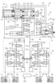
- FIG. 1 is a schematic diagram showing a braking device to which an embodiment of an electric cylinder device is applied.
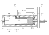
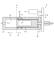
- FIG. 2 is a cross-sectional view that typically shows the structure of an electric cylinder provided in the electric cylinder device of FIG.
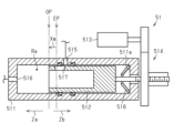
- FIG. 3 is a cross-sectional view that typically shows the structure of an electric cylinder provided in the electric cylinder device of FIG.
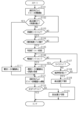
- FIG. 4 is a flowchart showing a flow of processing executed by a control device provided in the electric cylinder device of FIG.
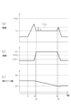
- FIG. 5 is a timing chart showing the transition of the current value when the piston is moved to the end position in the electric cylinder device of FIG.
- FIG. 6 is a cross-sectional view that typically shows the structure of an electric cylinder provided in the electric cylinder device of FIG.
- FIG 1 shows a vehicle braking device 20 as an example of application of an electric cylinder device.
- the braking device 20 includes a braking unit capable of applying a braking force to the wheels of the vehicle.
- the braking device 20 includes a control device 100 capable of controlling the braking unit.
- One example of the braking device 20 includes a first braking unit 50 and a second braking unit 23 as braking units.
- the first braking unit 50 includes an electric cylinder 51.
- the electric cylinder device is composed of the electric cylinder 51 and the control device 100.
- the electric cylinder device includes a reservoir tank 24.
- front wheels FL, FR and rear wheels RL, RR are shown as the wheels of the vehicle.
- the vehicle is equipped with a brake operating member 21.
- the brake operating member 21 can be operated by the driver of the vehicle.
- One example of the brake operating member 21 is a brake pedal.
- the control device 100 is an example of a processing circuit equipped in a vehicle.
- the vehicle may be equipped with other processing circuits, not limited to the control device 100. Some of the functions realized by the control device 100 may be realized by other processing circuits.
- the processing circuits equipped in the vehicle may be connected to each other so that they can send and receive information to each other. For example, a configuration can be adopted in which each processing circuit is connected to an in-vehicle network equipped in the vehicle.
- the processing circuits connected to the in-vehicle network can communicate with each other via the in-vehicle network.
- detection systems such as various sensors equipped in the vehicle may be connected to the in-vehicle network.
- the braking device 20 includes braking mechanisms corresponding to the wheels FL, FR, RL, and RR, respectively.
- the braking mechanisms can apply frictional braking forces to the wheels FL, FR, RL, and RR.
- the frictional braking forces applied by the braking mechanisms to the wheels FL, FR, RL, and RR can be adjusted by the braking device 20.
- Fig. 1 shows, as braking mechanisms, a front wheel braking mechanism 10A corresponding to the front wheels FL and FR, and a rear wheel braking mechanism 10B corresponding to the rear wheels RL and RR, respectively.
- the braking device 20 is a hydraulic braking device.
- the braking device 20 includes a reservoir tank 24 that stores brake fluid, and a hydraulic pressure generating device 22.
- One example of the hydraulic pressure generating device 22 is a so-called brake-by-wire type hydraulic pressure generating device.
- the hydraulic pressure generating device 22 can generate hydraulic pressure according to the amount of operation of the brake operating member 21.
- the hydraulic pressure generating device 22 is composed of a master device 30 and a first braking unit 50.
- the master device 30 can supply brake fluid to the second braking unit 23.
- the first braking unit 50 can supply brake fluid to the master device 30 and the second braking unit 23.
- the front wheel braking mechanism 10A and the rear wheel braking mechanism 10B will be described.
- the front wheel braking mechanism 10A has a wheel cylinder 11 to which brake fluid is supplied, a rotating plate 12 that rotates integrally with the wheel, and a friction material 13 that moves relative to the rotating plate 12 in the plate thickness direction of the rotating plate 12.
- the front wheel braking mechanism 10A is configured so that the higher the WC pressure Pwc, which is the hydraulic pressure in the wheel cylinder 11, the stronger the friction material 13 is pressed against the rotating plate 12.
- the rear wheel braking mechanism 10B is configured by the wheel cylinder 11, the rotating plate 12, and the friction material 13, similar to the front wheel braking mechanism 10A. According to the braking mechanism, the higher the WC pressure Pwc, the greater the frictional braking force applied to the wheels FL, FR, RL, and RR.
- An example of the master device 30 includes a master cylinder 31, a stroke simulator 32, a plurality of flow paths 331, 332, and 333 connected to the master cylinder 31, and a plurality of control valves 341 and 342 that control the flow of brake fluid.
- the stroke simulator 32 can generate a reaction force according to the amount of operation of the brake operating member 21.
- the master cylinder 31 includes a main cylinder 41 and a cover cylinder 42.
- the master cylinder 31 includes a master piston 43 and an input piston 44.
- the master cylinder 31 includes a master spring 45 that applies a force to push the master piston 43, and an input spring 46 that applies a force to push the input piston 44.
- the master piston 43 and the input piston 44 can move relative to the main cylinder 41 and the cover cylinder 42.
- the main cylinder 41 of the master cylinder 31 has a plate-shaped bottom wall 411 and a first peripheral wall 412 extending from the bottom wall 411 along the axis of the bottom wall 411.
- the main cylinder 41 further has a second peripheral wall 413 extending from the rear end of the first peripheral wall 412 along the axis of the first peripheral wall 412, and a first annular wall 414 extending from the rear end of the second peripheral wall 413 toward the axis of the second peripheral wall 413.
- Each of the first peripheral wall 412 and the second peripheral wall 413 is cylindrical.
- the first annular wall 414 has a hole into which the rear end of the master piston 43 described later is inserted.
- the inner diameter of the first peripheral wall 412 is smaller than the inner diameter of the second peripheral wall 413.
- a master chamber Rm is defined by the bottom wall 411, the first peripheral wall 412, and the master piston 43.
- the direction of movement of the master piston 43 toward the left in FIG. 1, i.e., the direction that reduces the volume of the master chamber Rm is referred to as the "forward" direction.
- the direction of movement of the master piston 43 opposite to the forward direction is referred to as the "rearward” direction.
- the rearward direction is also the direction that increases the volume of the master chamber Rm.
- a first fluid chamber R1 is defined by the second peripheral wall 413 and the master piston 43, and a servo chamber Rs is defined by the second peripheral wall 413, the first annular wall 414, and the master piston 43.
- the master chamber Rm is formed at a position toward the front end of the master cylinder 31.
- the first fluid chamber R1 is formed rearward of the master chamber Rm.
- the servo chamber Rs is formed rearward of the first fluid chamber R1.
- the master chamber Rm, the first fluid chamber R1, and the servo chamber Rs are not connected to each other.
- the cross-sectional area of the master chamber Rm and the cross-sectional area of the servo chamber Rs are equal.
- the cross-sectional area of the servo chamber Rs is the cross-sectional area of the servo chamber Rs when the master piston 43 is housed therein.
- the cover cylinder 42 of the master cylinder 31 has a cylindrical third peripheral wall 421 and a second annular wall 422 extending from the rear end of the third peripheral wall 421 toward the axis of the third peripheral wall 421.
- the third peripheral wall 421 is attached to the first annular wall 414 so that its axis coincides with that of the second peripheral wall 413 of the main cylinder 41.
- the second annular wall 422 has a hole into which the rear end of the input piston 44 described later is inserted.
- a second fluid chamber R2 is defined by the third peripheral wall 421, the second annular wall 422, and the first annular wall 414 of the main cylinder 41.
- the second fluid chamber R2 is formed rearward of the servo chamber Rs.
- the master piston 43 is accommodated in the master cylinder 31 in surface contact with the inner circumferential surface of the first peripheral wall 412, the inner circumferential surface of the second peripheral wall 413, and the inner circumferential surface of the first annular wall 414 of the main cylinder 41. Therefore, when the master piston 43 moves in the axial direction, the master piston 43 slides on the inner circumferential surface of the first peripheral wall 412, the inner circumferential surface of the second peripheral wall 413, and the inner circumferential surface of the first annular wall 414.
- the rear end of the master piston 43 protrudes rearward from the first annular wall 414 and is located in the second fluid chamber R2.
- the area of the rear end of the master piston 43 and the cross-sectional area of the first fluid chamber R1 are equal.
- the area of the rear end of the master piston 43 is the area that receives a force in the axial direction due to the fluid pressure of the second fluid chamber R2.
- the cross-sectional area of the first fluid chamber R1 is the cross-sectional area of the first fluid chamber R1 when the master piston 43 is accommodated.
- the input piston 44 is housed in the master cylinder 31 in face contact with the inner circumferential surface of the second annular wall 422 of the cover cylinder 42. Therefore, when the input piston 44 moves in the axial direction, the input piston 44 slides against the inner circumferential surface of the second annular wall 422. The rear end of the input piston 44 protrudes rearward beyond the second annular wall 422.
- the brake operating member 21 is connected to the rear end of the input piston 44. Therefore, the input piston 44 moves in a direction approaching the master piston 43 according to the amount of operation of the brake operating member 21. Furthermore, a gap is formed between the input piston 44 and the master piston 43 in the second fluid chamber R2.
- the master spring 45 is disposed in the master chamber Rm of the main cylinder 41.
- the master spring 45 applies a force to the master piston 43 that pushes the master piston 43 backward. Therefore, when the master piston 43 moves forward, the master spring 45 is elastically compressed.
- the input spring 46 is disposed in the second fluid chamber R2 of the cover cylinder 42.
- the input spring 46 applies a force to the input piston 44 that pushes the input piston 44 rearward. Therefore, when the input piston 44 moves forward, the input spring 46 is elastically compressed.
- the master chamber Rm is connected to the reservoir tank 24. More specifically, the rear end of the master chamber Rm is connected to the reservoir tank 24 via a port formed in the first peripheral wall 412 of the main cylinder 41. For this reason, when the master piston 43 moves forward from the initial position shown in FIG. 1, the master chamber Rm and the reservoir tank 24 are no longer connected. As a result, as the master piston 43 moves forward, the hydraulic pressure in the master chamber Rm increases. For example, when the hydraulic pressure in the servo chamber Rs increases, the master piston 43 moves forward due to the hydraulic pressure in the servo chamber Rs. This increases the hydraulic pressure in the master chamber Rm.
- the first flow path 331 connects the master chamber Rm to the second braking section 23.
- the first flow path 331 is a flow path that connects some of the multiple wheel cylinders 11 to the master chamber Rm.
- the first flow path 331 connects the wheel cylinders 11 for the front wheels FL and FR to the master chamber Rm.
- the second flow path 332 connects the first fluid chamber R1 to the second fluid chamber R2.
- the third flow path 333 connects the reservoir tank 24 to the second flow path 332.
- the first control valve 341 is a normally closed solenoid valve.
- the second control valve 342 is a normally open solenoid valve.
- the first control valve 341 is disposed between the connection point of the second flow path 332 with the third flow path 333 and the second fluid chamber R2.
- the second control valve 342 is provided in the third flow path 333.
- the stroke simulator 32 is disposed between the first fluid chamber R1 and the first control valve 341 in the second flow path 332.
- the stroke simulator 32 has a piston inside to which a force is applied from the back side by a spring.
- the stroke simulator 32 when brake fluid flows in from the second flow path 332 and the internal piston is displaced against the force of the spring, the stroke simulator 32 generates pressure in the brake fluid according to the displacement of the piston.
- the piston is not shown in the figure. Specifically, when the input piston 44 moves forward by the operation of the brake operating member 21 with the first control valve 341 open and the second control valve 342 closed, the volume of the second fluid chamber R2 decreases by the volume of the input piston 44 entering the second fluid chamber R2.
- the brake fluid flowing out from the second fluid chamber R2 to the second flow path 332 flows into the stroke simulator 32.
- the stroke simulator 32 generates the same pressure in the second fluid chamber R2 and the first fluid chamber R1, which are connected by the second flow path 332. If the area of the rear end of the master piston 43 protruding into the second fluid chamber R2 is equal to the cross-sectional area of the first fluid chamber R1, the master piston 43 will not be moved axially by this pressure when the same pressure is generated in the second fluid chamber R2 and the first fluid chamber R1.
- the first braking unit 50 includes an electric cylinder 51 having a first electric motor 513 as a power source.
- the first braking unit 50 can adjust the WC pressure Pwc by the electric cylinder 51 that operates according to the driving amount of the first electric motor 513. That is, the first braking unit 50 can generate braking forces on the wheels FL, FR, RL, and RR of the vehicle.
- the first braking unit 50 includes an electric cylinder 51 , a hydraulic pressure regulating valve 551 , and a check valve 552 .
- the first braking unit 50 has a fourth flow path 54 that connects the electric cylinder 51 and the reservoir tank 24.
- the first braking unit 50 has a sixth flow path 58 that connects the second braking unit 23 and the electric cylinder 51.
- the first braking unit 50 has a fifth flow path 55 that connects the servo chamber Rs of the master cylinder 31 and the sixth flow path 58.
- the hydraulic pressure adjustment valve 551 is provided in the fifth flow path 55.
- the hydraulic pressure adjustment valve 551 is an electromagnetic valve that adjusts the pressure difference between the portion of the fifth flow path 55 that is closer to the servo chamber Rs than the hydraulic pressure adjustment valve 551 and the portion of the fifth flow path 55 that is closer to the electric cylinder 51 than the hydraulic pressure adjustment valve 551. In other words, the hydraulic pressure adjustment valve 551 can adjust the amount of brake fluid supplied to the servo chamber Rs.
- the check valve 552 is provided in the fifth flow path 55 in parallel with the hydraulic pressure adjustment valve 551.
- the check valve 552 allows the flow of brake fluid through the check valve 552 from the servo chamber Rs toward the electric cylinder 51.
- the check valve 552 restricts the flow of brake fluid through the check valve 552 in the direction from the electric cylinder 51 to the servo chamber Rs.
- the electric cylinder 51 included in the first braking unit 50 is provided between the fourth flow path 54 and the sixth flow path 58.
- the fourth flow path 54 is connected to an input port 515 of the electric cylinder 51.
- the sixth flow path 58 is connected to an output port 516 of the electric cylinder 51. The input port 515 and the output port 516 will be described later.
- the configuration of the electric cylinder 51 will be described with reference to FIGS.
- the electric cylinder 51 includes a cylinder 511, a piston 512, a first electric motor 513, and a conversion mechanism 514.
- the piston 512 is provided in a state in which it can slide within the cylinder 511.
- the first electric motor 513 is a power source for the electric cylinder 51.
- the conversion mechanism 514 converts the rotational motion of the output shaft of the first electric motor 513 into the linear motion of the piston 512.
- the cylinder 511 defines a hydraulic chamber Re into which brake fluid is introduced by the peripheral wall of the cylinder 511 and the piston 512.
- the position of the piston 512 inside the cylinder 511 can be changed by driving the first electric motor 513.
- the direction in which the piston 512 moves that reduces the volume of the hydraulic chamber Re is referred to as the "forward direction Za”.
- the piston 512 moves in the opposite direction to the forward direction Za is referred to as the "reverse direction Zb”.
- the reverse direction Zb is also the direction in which the piston 512 moves that increases the volume of the hydraulic chamber Re.
- the control device 100 uses an end position EP and an origin position OP.
- Figure 2 shows the electric cylinder 51 with the piston 512 located at the end position EP.
- the end position EP is the position where the piston 512 has been moved to the end in the backward direction Zb.
- Figure 3 shows the electric cylinder 51 with the piston 512 located at the origin position OP.
- the origin position OP is the position where the piston 512 has been moved a specified amount of movement Xm in the forward direction Za from the end position EP.
- the origin position OP serves as the base point when hydraulic pressure is generated by the electric cylinder 51.
- the electric cylinder 51 is equipped with an elastic body 518.
- the elastic body 518 applies a force to the piston 512 that pushes the piston 512 in the forward direction Za when the piston 512 is located at the end position EP.
- the elastic body 518 is arranged so that the contact of the piston 512 with the elastic body 518 restricts the movement of the piston 512 in the backward direction Zb.
- the elastic body 518 is arranged so as to contact the rear inner wall 511a of the cylinder 511.
- the elastic body 518 is arranged so as to contact the end face in the backward direction Zb of the piston 512 located at the end position EP.
- the elastic body 518 is a disc spring.
- a leaf spring, a coil spring, or the like can also be used as the elastic body 518.
- An elastic member molded from an elastic material such as elastomer or rubber can also be used as the elastic body 518. Note that Figures 2, 3, and 6 show a disc spring as the elastic body 518 that can be deformed into a flat plate shape.
- the end position EP is set as a position between the position of the piston 512 where the elastic body 518 begins to deform elastically and the position of the piston 512 where the elastic body 518 deforms to its limit.
- the elastic body 518 illustrated in Figure 2 shows a state where it has begun to elastically deform, as an example.
- An input port 515 and an output port 516 are formed on the peripheral wall of the cylinder 511 as ports connecting the hydraulic chamber Re with the outside.
- a through hole 517 is formed in the piston 512.
- the through hole 517 is formed at a position that allows communication between the input port 515 and the hydraulic chamber Re when the piston 512 is located at the end position EP.
- the hydraulic chamber Re of the cylinder 511 is connected to the fourth flow path 54 via the input port 515 and the through hole 517.
- the hydraulic chamber Re of the cylinder 511 is connected to the reservoir tank 24 via the input port 515 and the through hole 517.
- the input port 515 is open when the piston 512 is located between the end position EP and the origin position OP.
- the electric cylinder 51 is configured so that when the piston 512 moves in the forward direction Za from the origin position OP, the piston 512 closes the input port 515. If the piston 512 moves further in the forward direction Za after the input port 515 is closed by the piston 512 in this way, the hydraulic pressure in the hydraulic chamber Re increases.
- the output port 516 of the cylinder 511 is connected to the second braking section 23 and the fifth flow path 55 via the sixth flow path 58.
- the output port 516 is always open, regardless of the position of the piston 512. Therefore, when the input port 515 is blocked by the piston 512, the brake fluid in the hydraulic chamber Re is discharged from the output port 516 to the outside of the cylinder 511 when the piston 512 moves in the forward direction Za.
- the electric cylinder 51 of the braking device 20 does not include a spring that applies a force to push the piston 512 in the backward direction Zb.
- the electric cylinder 51 may include a spring that applies a force to push the piston 512 in the backward direction Zb.
- the first braking unit 50 includes a release flow passage 56 and a release valve 57 disposed in the release flow passage 56.
- the release flow passage 56 is a flow passage that connects the reservoir tank 24 and the wheel cylinder 11 so as to bypass the electric cylinder 51.
- a first end of the release flow passage 56 is connected to the fourth flow passage 54, while a second end of the release flow passage 56 is connected to the sixth flow passage 58.
- the release flow passage 56 connects between the reservoir tank 24 and the input port 515 in the fourth flow passage 54, and between the output port 516 and the second braking unit 23 in the sixth flow passage 58.
- the release valve 57 is a normally closed solenoid valve. Therefore, when control to open the release valve 57 is not being performed, the release flow passage 56 is closed.
- the second braking unit 23 includes a second electric motor 64 as a power source.
- the second braking unit 23 can generate braking forces on the wheels FL, FR, RL, and RR of the vehicle according to the driving amount of the second electric motor 64.
- the second braking unit 23 is interposed between the first braking unit 50 and the wheel cylinder 11.
- the second braking unit 23 is a braking actuator capable of individually adjusting the WC pressure Pwc of each of the wheels FL, FR, RL, and RR.
- the second braking unit 23 includes pumps 631 and 632 that discharge brake fluid.
- the pumps 631 and 632 are driven by a second electric motor 64.
- the second braking section 23 can increase the WC pressure Pwc without increasing the hydraulic pressure of the brake fluid adjusted by the first braking section 50.
- the braking device 20 has a redundant configuration in which the first braking section 50 is on the upstream side and the second braking section 23 is on the downstream side.
- the second braking unit 23 has two hydraulic circuits 611, 612.
- the first hydraulic circuit 611 is connected to two wheel cylinders 11 for the front wheels FL, FR.
- the second hydraulic circuit 612 is connected to two wheel cylinders 11 for the rear wheels RL, RR.
- the first hydraulic circuit 611 is connected to the reservoir tank 24 via the first flow path 331 and the master chamber Rm.
- a first differential pressure adjustment valve 621 which is a normally open linear solenoid valve, is provided in the hydraulic path connecting the connection point with the first flow path 331 and the wheel cylinder 11.
- a check valve is provided in parallel with the first differential pressure adjustment valve 621 in the hydraulic path. The check valve allows the flow of brake fluid through the check valve from the first flow path 331 in the direction toward the wheel cylinder 11. On the other hand, the check valve restricts the flow of brake fluid through the check valve from the wheel cylinder 11 in the direction toward the first flow path 331.
- the second hydraulic circuit 612 is connected to the reservoir tank 24 via the fourth flow path 54, the electric cylinder 51, and the sixth flow path 58.
- a second differential pressure adjustment valve 622 which is a normally open linear solenoid valve, is provided in the hydraulic path connecting the connection point with the sixth flow path 58 and the wheel cylinder 11.
- a check valve is provided in parallel with the second differential pressure adjustment valve 622 in this hydraulic path. The check valve allows the flow of brake fluid through the check valve from the sixth flow path 58 in the direction toward the wheel cylinder 11. On the other hand, the check valve restricts the flow of brake fluid through the check valve from the wheel cylinder 11 in the direction toward the sixth flow path 58.
- the pump 631 is provided in the first hydraulic circuit 611.
- the pump 631 supplies brake fluid to a fluid path connecting the first differential pressure adjustment valve 621 and the wheel cylinder 11.
- a check valve is arranged in series between the pump 631 and the fluid path. This check valve allows the brake fluid to flow in the direction discharged from the pump 631. On the other hand, the check valve restricts the flow of brake fluid discharged from the pump 631 in the direction returning to the pump 631.
- the pump 632 is provided in the second hydraulic circuit 612.
- the pump 632 supplies brake fluid to a fluid path connecting the second differential pressure adjustment valve 622 and the wheel cylinder 11.
- a check valve is arranged in series between the pump 632 and the fluid path. This check valve allows the brake fluid to flow in the direction discharged from the pump 632. On the other hand, the check valve restricts the flow of brake fluid discharged from the pump 632 in the direction returning to the pump 632.
- paths 65a and 65b in the same number as the wheel cylinders 11 connected to the hydraulic circuit 611.
- paths 65c and 65d in the same number as the wheel cylinders 11 connected to the hydraulic circuit 612.
- the paths 65a to 65d are provided with a holding valve 66 that is closed when restricting an increase in hydraulic pressure in the wheel cylinder 11, and a pressure reducing valve 67 that is opened when the hydraulic pressure is reduced.
- the holding valve 66 is disposed in the hydraulic path on the wheel cylinder 11 side of the differential pressure adjustment valves 621 and 622.
- the holding valves 66 are normally open solenoid valves, and the pressure reducing valves 67 are normally closed solenoid valves.
- Each of the multiple paths 65a to 65d has a check valve provided in parallel with the retention valve 66.
- the check valve allows the flow of brake fluid through the check valve in the direction from the wheel cylinder 11 to the differential pressure adjustment valves 621, 622.
- the check valve restricts the flow of brake fluid through the check valve in the direction from the differential pressure adjustment valves 621, 622 to the wheel cylinder 11.
- the multiple hydraulic circuits 611, 612 are connected to reservoirs 681, 682 that temporarily store the brake fluid that flows out from the wheel cylinder 11 through the pressure reducing valve 67 when the pressure reducing valve 67 is open.
- the multiple reservoirs 681, 682 are connected to pumps 631, 632 via suction flow paths 691, 692.
- the reservoir 681 is connected to the fluid path connecting the first differential pressure adjustment valve 621 and the master chamber Rm via a tank-side flow path 701.
- the reservoir 682 is connected to the fluid path connecting the connection point with the sixth flow path 58 in the second hydraulic circuit 612 and the second differential pressure adjustment valve 622 via a tank-side flow path 702.
- the pumps 631, 632 can pump brake fluid from the reservoir tank 24 via the reservoirs 681, 682.
- the pumps 631, 632 discharge the pumped brake fluid into a fluid path between the differential pressure adjustment valves 621, 622 and the retention valve 66.
- the fluid path between the fluid path and the pumps 631, 632 is called the "intermediate fluid path 711, 712."
- the detection system of the braking device 20 includes a plurality of sensors. Detection signals of the sensors are input to a control device 100 of the braking device 20.
- Fig. 1 shows the plurality of sensors, which are a master hydraulic pressure sensor 351, an input hydraulic pressure sensor 352, a control pressure sensor 353, a stroke sensor SE1, a rotation angle sensor SE2, and a current sensor SE3.
- the master hydraulic pressure sensor 351 detects the hydraulic pressure in the master chamber Rm.
- the master hydraulic pressure sensor 351 is provided in the first flow path 331.
- the hydraulic pressure in the master chamber Rm based on the detection value of the master hydraulic pressure sensor 351 is called the "master pressure.”
- the input fluid pressure sensor 352 detects the fluid pressure in the second fluid chamber R2.
- the input fluid pressure sensor 352 is connected to a position in the second flow path 332 between the first control valve 341 and the second fluid chamber R2.
- the fluid pressure in the second fluid chamber R2 based on the detection value of the input fluid pressure sensor 352 is referred to as the "input fluid pressure.”
- the control pressure sensor 353 is a pressure sensor that detects the hydraulic pressure of the brake fluid supplied from the electric cylinder 51.
- the control pressure sensor 353 is provided near the output port 516 of the electric cylinder 51.
- FIG. 1 shows a configuration in which the control pressure sensor 353 is connected between the release valve 57 in the release flow passage 56 and the output port 516.
- the discharge hydraulic pressure of the electric cylinder 51 based on the detection value of the control pressure sensor 353 is referred to as "pressure P.”
- the stroke sensor SE 1 detects the amount of operation of the brake operating member 21 .
- the rotation angle sensor SE2 detects the rotation angle of the first electric motor 513 which is the power source of the electric cylinder 51.
- the rotation angle of the first electric motor 513 based on the detection value of the rotation angle sensor SE2 is referred to as the "rotation angle ⁇ .”
- the position of the piston 512 can be estimated based on the rotation angle ⁇ .
- the rotation speed S of the first electric motor 513 can be calculated based on the rotation angle ⁇ .
- the current sensor SE3 can detect the value of the current flowing through the first electric motor 513.
- the current value of the first electric motor 513 based on the detection value of the current sensor SE3 is referred to as the "current value T.”
- the control device 100 can control the various solenoid valves 341, 342, 551, 57 and the first electric motor 513 provided in the hydraulic pressure generating device 22, and the various solenoid valves 621, 622, 66, 67 and the second electric motor 64 provided in the second braking unit 23.
- the control device 100 can execute a piston position setting process.
- the piston position setting process is a process for setting the relative position of the piston 512 with respect to the input port 515 in relation to the control of the electric cylinder 51.
- the piston position setting process includes an end point movement process that moves the piston 512 to the end point position EP, and an origin movement process that moves the piston 512 from the end point position EP in the forward direction Za by a movement amount Xm.
- the origin movement process can be executed after the piston 512 has been moved to the end point position EP by the end point movement process.
- FIG. 4 shows the flow of the process executed by the control device 100.
- the control device 100 can execute this processing routine when starting the braking device 20.
- the braking device 20 starts, for example, when the start switch of the vehicle is turned from off to on.
- step S101 the control device 100 starts driving the first electric motor 513 to move the piston 512 in the backward direction Zb. At this time, the control device 100 performs feedback control so that the rotation speed S of the first electric motor 513 follows the target rotation speed ST.
- the target rotation speed ST is, for example, a constant value that is set in advance.
- step S102 the control device 100 determines whether the piston 512 has reached the end position EP.
- the control device 100 detects that the piston 512 has reached the end position EP, for example, when the current value T is greater than the second determination value Tth2 and the rotation speed S is less than the first threshold value Sth1.
- the first threshold value Sth1 is set as a threshold value for determining whether the rotation of the first electric motor 513 has stopped. For example, when the rotation speed S, which was equal to or greater than the first threshold value Sth1, becomes smaller than the first threshold value Sth1, it can be determined that the rotation of the first electric motor 513 has stopped.
- the second determination value Tth2 can be set, for example, to a value greater than the inrush current when driving of the first electric motor 513 is started.
- the control device 100 determines that the piston 512 has reached the end position EP.
- step S102 If the process in step S102 detects that the piston 512 has reached the end position EP (S102: YES), the control device 100 transitions to step S111.
- step S111 the control device 100 temporarily stops driving the first electric motor 513.
- the control device 100 may acquire the rotation angle ⁇ at the time when the driving of the first electric motor 513 is stopped as the end point rotation angle ⁇ ep.
- the end point rotation angle ⁇ ep corresponds to the rotation angle ⁇ when the piston 512 moves to the end point position EP.
- the control device 100 transitions to step S121.
- step S103 the control device 100 determines whether the rotation speed S is greater than the second threshold value Sth2.
- the second threshold value Sth2 is set as a threshold value for determining whether the first electric motor 513 has started to move.
- the second threshold value Sth2 is a value greater than the first threshold value Sth1. For example, when the rotation speed S, which was equal to or less than the second threshold value Sth2, becomes greater than the second threshold value Sth2, it can be determined that the first electric motor 513 has started to move.
- the first electric motor 513 starting to move means that the piston 512 has begun to move in the backward direction Zb.
- step S104 If the rotation speed S is equal to or less than the second threshold value Sth2 (S103: NO), the control device 100 transitions the process back to step S102. On the other hand, if the rotation speed S is greater than the second threshold value Sth2 (S103: YES), the control device 100 transitions the process to step S104.
- step S102 the process of step S102 is repeatedly executed until the rotation speed S becomes greater than the second threshold value Sth2 by the process of step S103, that is, until the first electric motor 513 starts to move.
- step S102 the rotation speed S is equal to or greater than the first threshold value Sth1
- the current value T is equal to or less than the second determination value Tth2
- step S111 the drive of the first electric motor 513 is temporarily stopped.
- the rotation speed S is equal to or greater than the first threshold value Sth1 and the current value T is greater than the second determination value Tth2. Or, the rotation speed S is smaller than the first threshold value Sth1 and the current value T is equal to or less than the second determination value Tth2. Or, the rotation speed S is equal to or greater than the first threshold value Sth1 and the current value T is equal to or less than the second determination value Tth2.
- step S104 the control device 100 determines whether the rotation speed S has reached the target rotation speed ST.
- the control device 100 shifts the process to step S104. That is, the control device 100 repeatedly determines whether the rotation speed S has reached the target rotation speed ST until the rotation speed S reaches the target rotation speed ST. During this time, the feedback control of the first electric motor 513 is continued, so that the difference between the rotation speed S and the target rotation speed ST becomes smaller as time passes.
- the control device 100 can determine whether the rotation speed S has reached the target rotation speed ST, for example, based on the rotation speed S and the target rotation speed ST.
- the determination of whether the rotation speed S has reached the target rotation speed ST can also be performed based on the duration during which the state in which the rotation speed S is greater than the second threshold value Sth2 continues. For example, when the duration during which the rotation speed S is greater than the second threshold value Sth2 is longer than a rotation speed determination time calculated in advance by an experiment or the like, it may be determined that the rotation speed S has reached the target rotation speed ST.
- step S105 the control device 100 sets a first determination value Tth1.
- the control device 100 sets the first determination value Tth1 based on the current value T flowing through the first electric motor 513 when the rotation speed S follows the target rotation speed ST after the first electric motor 513 starts moving.
- the first determination value Tth1 will be described in more detail.
- the first determination value Tth1 is a value that is set for determining that the piston 512 has moved to the end position EP.
- the control device 100 sets the first determination value Tth1 based on the current value T when the rotation speed S of the first electric motor 513 is following the target rotation speed ST.
- the first determination value Tth1 is set to a value smaller than the second determination value Tth2.
- the first judgment value Tth1 can be calculated as a value that is larger than the current value T when the rotation speed S is following the target rotation speed ST by an increase amount d.
- the increase amount d is a predetermined amount that is set based on the elasticity of the elastic body 518.
- the first judgment value Tth1 is a value that corresponds to the current value T when the piston 512 is moved to the end position EP while elastically deforming the elastic body 518.
- the increase amount d can be set to a value that is larger the more difficult it is for the elastic body 518 to elastically deform.
- step S106 the control device 100 determines whether the current value T is greater than the first determination value Tth1. If the current value T is greater than the first determination value Tth1 (S106: YES), the control device 100 proceeds to step S110. On the other hand, if the current value T is equal to or less than the first determination value Tth1 (S106: NO), the control device 100 proceeds to step S107.
- step S107 the control device 100 determines whether the rotation speed S is smaller than the first threshold value Sth1. If the rotation speed S is smaller than the first threshold value Sth1, i.e., if the first electric motor 513 has stopped rotating (S107: YES), the control device 100 proceeds to step S110. For example, if the first electric motor 513 has stopped rotating before it is detected that the current value T has become larger than the first determination value Tth1, a positive determination is made in the processing of step S107 and the processing proceeds to step S110. On the other hand, if the rotation speed S is equal to or smaller than the first threshold value Sth1, i.e., if the first electric motor 513 has not stopped rotating (S107: NO), the control device 100 proceeds to step S108.
- step S108 the control device 100 determines whether the time during which the first electric motor 513 is driven to move the piston 512 in the backward direction Zb, i.e., the backward time, is longer than the judgment time.
- the judgment time is a value calculated in advance by experiments, etc.
- the judgment time can be set as the time required to move the piston 512 from the end in the forward direction Za to the end BE in the backward direction Zb when the first electric motor 513 is driven at the target rotation speed ST, for example. In other words, the time during which the first electric motor 513 is driven is longer than the judgment time, which means that an abnormality has occurred.
- the state in which the piston has moved to the end BE in the backward direction Zb is a state in which the piston 512 cannot move further backward even if the maximum driving force is generated when the piston 512 is moved in the backward direction Zb.
- the state in which the piston has moved to the end BE in the backward direction Zb is a state in which the piston 512 cannot move further backward mechanically when the piston 512 is moved in the backward direction Zb. This will be explained using FIG. 6.
- FIG. 6 illustrates an example of the electric cylinder 51 in a state where the piston 512 has moved in the backward direction Zb from the end position EP and is abutting against the rear inner wall 511a of the cylinder 511 with the elastic body 518 sandwiched between them.
- the disc spring serving as the elastic body 518 at this time is deformed to its limit and is in the shape of a flat plate.
- the end face of the piston 512 in the backward direction Zb has moved to the end BE in the backward direction Zb.
- the state where the end face of the piston in the backward direction is in contact with the rear inner wall corresponds to the state where the piston has moved to the end in the backward direction.
- step S109 the control device 100 determines that an abnormality has occurred in the detection of the end position EP. For example, the control device 100 may store the occurrence of the abnormality as history in a storage medium such as a memory. The control device 100 then ends this processing routine.
- the control device 100 transitions the process to step S106 again.
- steps S106, S107, and S108 can be summarized as follows. That is, if either the current value T is greater than the first judgment value Tth1 or the rotation speed S is less than the first threshold value Sth1 while the reverse time is less than the judgment time, the processing of step S110 is executed. If neither the current value T is greater than the first judgment value Tth1 nor the rotation speed S is less than the first threshold value Sth1 while the reverse time is less than the judgment time, the driving of the first electric motor 513 continues.
- step S110 the control device 100 temporarily stops driving the first electric motor 513. That is, when the current value T increases above the first judgment value Tth1, the control device 100 determines that the piston 512 has reached the end position EP and ends the driving of the first electric motor 513. Alternatively, when the rotation speed S becomes smaller than the first threshold value Sth1, the control device 100 determines that the piston 512 has reached the end position EP and ends the driving of the first electric motor 513.
- step S110 the control device 100 acquires the rotation angle ⁇ at the time when the piston 512 reaches the end position EP as the end rotation angle ⁇ ep. For example, the control device 100 acquires the rotation angle ⁇ at the time when the current value T increases above the first judgment value Tth1 as the end rotation angle ⁇ ep. For example, the control device 100 acquires the rotation angle ⁇ at the time when the rotation speed S becomes smaller than the first threshold value Sth1 as the end rotation angle ⁇ ep.
- the control device 100 proceeds to the processing of step S121.
- step S121 the control device 100 starts driving the first electric motor 513 to move the piston 512 in the forward direction Za.
- the control device 100 has moved the piston 512 in the forward direction Za by a specified movement amount Xm, it ends driving the first electric motor 513.
- the movement amount Xm is the amount of movement of the piston 512 from the end position EP to the origin position OP, and is a value calculated in advance by experiments, etc.
- the control device 100 drives the first electric motor 513 to move the piston 512 in the forward direction Za based on the end rotation angle ⁇ ep and the rotation angle for moving the piston 512 by the movement amount Xm in the forward direction Za.
- the control device 100 uses the position of the piston 512 corresponding to the end rotation angle ⁇ ep as a base point and moves the piston 512 to a position that is a movement amount Xm away from the base point in the forward direction Za. Therefore, the amount that the piston 512 actually moves in the forward direction Za from the point at which driving of the first electric motor 513 begins to move the piston 512 in the forward direction Za is not necessarily equal to the movement amount Xm.
- control device 100 may execute the process of step S121 following the process of step S111.
- control device 100 may drive the first electric motor 513 so as to move the piston 512 in the forward direction Za by a movement amount Xm from the point in time when the control device 100 starts driving the first electric motor 513 to move the piston 512 in the forward direction Za.
- step S121 When the piston 512 is moved in the forward direction Za in the process of step S121, the control device 100 transitions the process to step S122.
- step S122 the control device 100 determines whether the pressure P is smaller than a blockage determination value Pth.
- the blockage determination value Pth is set to a value calculated in advance by experiments or the like as a value indicating that the input port 515 is blocked by the piston 512 when the pressure P is equal to or greater than the blockage determination value Pth. Therefore, the pressure P being smaller than the blockage determination value Pth indicates that the input port 515 is not blocked by the piston 512. In other words, this indicates that the piston 512 is positioned further in the backward direction Zb than the position where the input port 515 is blocked by the piston 512.
- the control device 100 ends this processing routine.
- the control device 100 acquires the position of the piston 512 at this time as the origin position OP.
- the control device 100 updates the origin position OP stored in a storage medium such as a memory to the newly acquired origin position OP.
- the origin position OP can be acquired, for example, as the rotation angle ⁇ of the first electric motor 513.
- step S122 the control device 100 transitions the process to step S123. If the pressure P is equal to or greater than the blockage determination value Pth, it can be inferred that the piston 512 has moved too far in the forward direction Za.
- step S123 the control device 100 determines that an abnormality has occurred in the detection of the origin position OP.
- the control device 100 may store the occurrence of the abnormality as history in a storage medium such as a memory. The control device 100 then ends this processing routine.
- steps S101 to S111 correspond to the end point movement process.
- steps S121 to S123 correspond to the origin movement process.
- the end point rotation angle ⁇ ep obtained in the processing of step S110 may be erased when the piston position setting process ends, or may be stored as the rotation angle ⁇ corresponding to the end point position EP and retained after the piston position setting process ends.
- the piston position setting process is started at time t1, or in other words, the end point movement process is started at time t1.
- the current value T starts to increase at time t1.
- an inrush current occurs temporarily.
- Fig. 5A illustrates an example of the second determination value Tth2.
- FIG. 5B illustrates an example of the first threshold value Sth1, which is a value smaller than the second threshold value Sth2.
- the rotation speed S reaches the target rotation speed ST. This causes a process to set the first judgment value Tth1 (S105).
- the period during which an inrush current occurs passes and the current value T remains at a constant value.
- the current value T at this time is shown as the reference current value Tx.
- the control device 100 sets a value that is greater than the reference current value Tx by the increase amount d as the first judgment value Tth1.
- the current value T starts to increase above the reference current value Tx.
- the rotation speed S starts to decrease. This is because the piston 512 comes into contact with the elastic body 518 at time t4. As the elastic body 518 elastically deforms, the current value T increases and the rotation speed S decreases.
- the current value T becomes greater than the first judgment value Tth1.
- the drive of the first electric motor 513 is stopped (S110).
- the control device 100 acquires the rotation angle ⁇ at this time as the end point rotation angle ⁇ ep.
- the electric cylinder device of this embodiment by setting the first judgment value Tth1 to a value that is greater than the reference current value Tx by the increase amount d, it is possible to determine that the end position EP has been reached before the current value T becomes excessively large. In other words, the current value T is unlikely to become excessively large until the piston 512 has finished moving in the backward direction Zb. Therefore, the drive of the first electric motor 513 can be stopped before the current value T becomes excessively large. This makes it possible to prevent excessive load from being placed on the electric cylinder 51.
- the elastic body 518 is provided, and therefore the rate of change of the current value T while the elastic body 518 is being elastically deformed by the movement of the piston 512 in the backward direction Zb is relatively small.
- the rate of change is gentler compared to when the piston hits an end in the backward direction in an electric cylinder device not provided with an elastic body. Therefore, when detecting the end position EP, a steep increase in the current value T can be suppressed. This makes it possible to suppress the current value T from becoming excessively large.
- the end position EP can be detected while the elastic body 518 is elastically deformed. In this way, in the electric cylinder device of this embodiment, the end position EP can be detected without the piston 512 hitting the end BE in the backward direction Zb.
- the origin movement process can be executed.
- the piston 512 moves to a position that is a movement amount Xm away in the forward direction Za from the position corresponding to the end point rotation angle ⁇ ep. This allows the control device 100 to set the origin position OP based on the end point rotation angle ⁇ ep and the movement amount Xm.
- the piston 512 When the driving of the first electric motor 513 ends at time t5, the piston 512 also stops moving in the backward direction Zb. In the example shown in FIG. 5(c), the position of the piston 512 after time t5 has moved from the position of the piston 512 at time t5.
- the piston 512 may move without being driven by the first electric motor 513.
- the piston 512 may move in the backward direction Zb due to a delayed response after the first electric motor 513 is stopped.
- the piston 512 may move when pushed in the forward direction Za by the elastic body 518. If the piston 512 moves further after it has been moved by the end position movement process, an error may occur when setting the origin position OP.
- the electric cylinder device of this embodiment is configured to obtain the rotation angle ⁇ when the end position EP is reached as the end rotation angle ⁇ ep, and drive the first electric motor 513 based on the end rotation angle ⁇ ep when moving the piston 512 in the forward direction Za. Therefore, the piston 512 can be moved accurately by the movement amount Xm from the position detected as the end position EP. This allows the origin position OP to be set with high precision.
- the dynamic friction resistance may vary when the piston 512 is moved.
- the dynamic friction resistance may vary due to expansion, contraction, aging, and the like of the components that make up the electric cylinder 51. If the dynamic friction resistance varies when the piston 512 is moved, the torque generated by the first electric motor 513 varies according to the dynamic friction resistance. For this reason, for example, the current value T flowing through the first electric motor 513 when the rotation speed S is made to follow the target rotation speed ST varies.
- the variation in dynamic friction resistance may be a factor in reducing the accuracy of determining that the end position EP has been reached.
- the electric cylinder device of this embodiment sets the first judgment value Tth1 using the current value T when the rotation speed S is following the target rotation speed ST as the reference current value Tx. For example, if the current value T when the rotation speed S is following the target rotation speed ST is relatively large, the first judgment value Tth1 is also set to be large. For example, if the current value T when the rotation speed S is following the target rotation speed ST is relatively small, the first judgment value Tth1 is also set to be small. Therefore, even if the dynamic friction resistance fluctuates as described above, it is possible to ensure accuracy in determining that the end position EP has been reached. This makes it possible to reduce variation in the estimated end position EP. By being able to accurately detect the end position EP, it is possible to accurately set the origin position OP.
- the electric cylinder device of this embodiment allows the origin position OP to be set with high precision, improving responsiveness when generating hydraulic pressure by controlling the electric cylinder 51.
- the position of the piston 512 at that point in time can be set as the end position EP (S111). This makes it possible to prevent the first electric motor 513 from continuing to be driven even though the piston 512 has moved to the end BE in the backward direction Zb.
- the processing routine is configured to end after the processing of step S109 in FIG. 4 is executed.
- the processing of step S109 may be executed and then the processing of moving the piston 512 in the forward direction Za may be executed.
- the processing may proceed to step S121 after the processing of step S109 is executed.
- the piston 512 is moved in the forward direction Za by a movement amount Xm from the position of the piston 512 at the time when the processing of step S108 was judged to be positive.
- step S102 detects that the piston 512 has reached the end position EP when the current value T is greater than the second judgment value Tth2 and the rotation speed S is less than the first threshold value Sth1.
- the process of step S102 can determine whether or not the piston 512 has reached the end position EP regardless of the rotation speed S. For example, in step S102, if the current value T is equal to or less than the second judgment value Tth2, the process may proceed to step S103, whereas if the current value T is greater than the second judgment value Tth2, the process may proceed to step S111.
- the origin moving process of steps S121 to S123 is executed by shifting the process to step S121 after step S111.
- the following retry process may be executed after step S111.
- the drive of the first electric motor 513 is stopped as the process of step S111, and then the piston 512 is moved in the forward direction Za by a predetermined retry distance. Then, the process returns to step S101, and the piston position setting process is started again.
- the process of step S111 and the retry process may be executed repeatedly.
- the origin moving process may be executed by shifting the process from step S111 to step S121, for example.
- the brake fluid exemplified in the above embodiment is an example of a hydraulic fluid.
- the wheel cylinder 11 for the rear wheels RL, RR in the above embodiment is an example of a supply target of the hydraulic fluid supplied by the electric cylinder 51.
- the master cylinder 31 is an example of a supply target of the hydraulic fluid supplied by the electric cylinder 51.
- the wheel cylinder 11 for the front wheels FL, FR is supplied with the brake fluid discharged by the electric cylinder 51 via the master cylinder 31. Therefore, the wheel cylinder 11 for the front wheels FL, FR can also be said to be an example of a supply target of the hydraulic fluid supplied by the electric cylinder 51.
- the force with which the piston 512, which has moved to the end of the cylinder 511 in the backward direction Zb, is pushed in the forward direction Za by the elastic body 518 is reduced.
- the piston 512 when the piston 512 is moved to the end position EP, as shown in FIG. 6, the piston 512 may hit the rear inner wall 511a of the cylinder 511 with the elastic body 518 sandwiched between them. Therefore, it is preferable to set the increment d so that even if the elastic body 518 sags, it is determined that the piston 512 has moved to the end position EP before the piston 512 hits the rear inner wall 511a of the cylinder 511 with the elastic body 518 sandwiched between them.
- the increment d may be a value set in consideration of the sagging that may occur in the elastic body 518. Furthermore, the increment d may be set so that the pressing force by the piston 512 when the first electric motor 513 is driven so that a current value increased by the increment d from the reference current value Tx flows is as follows. The increase amount d may be set so that a pressing force is exerted that keeps the settling of the elastic body 518 within an acceptable range, even if the deformation of the elastic body 518 caused by being pressed by the piston 512 is repeated a predetermined number of times.
- the processing circuit of the control device 100 etc. can be configured as follows.
- the processing circuit can be configured as a circuit having one or more processors that execute various processes according to a computer program.
- the processing circuit can be configured as a circuit having one or more hardware circuits that execute various processes.
- the processing circuit can be configured as a circuit that combines one or more processors that execute some of the various processes with one or more hardware circuits that execute the remaining of the various processes.
- the processor includes a processing unit such as a CPU.
- the processor includes a memory such as a RAM and a ROM.
- the memory stores program codes or instructions configured to cause the processing unit to execute a process.
- the memory i.e., storage medium, includes any available medium accessible by a general-purpose or special-purpose computer.
- the hardware circuit may include, for example, an ASIC, which is an application-specific integrated circuit. Another example of the hardware circuit is an FPGA, etc.
Landscapes
- Engineering & Computer Science (AREA)
- Mechanical Engineering (AREA)
- Transportation (AREA)
- General Engineering & Computer Science (AREA)
- Physics & Mathematics (AREA)
- Fluid Mechanics (AREA)
- Regulating Braking Force (AREA)
- Braking Systems And Boosters (AREA)
Abstract
Description
図1は、電動シリンダ装置を適用する一例として、車両の制動装置20を示す。制動装置20は、車両の車輪に制動力を付与することができる制動部を備えている。制動装置20は、制動部を制御することができる制御装置100を備えている。制動装置20の一例は、制動部として第1制動部50及び第2制動部23を備えている。第1制動部50は、電動シリンダ51を備えている。電動シリンダ装置は、電動シリンダ51と制御装置100とによって構成されている。電動シリンダ装置は、リザーバタンク24を備えている。
制動装置20は、車輪FL,FR,RL,RRのそれぞれに対応した制動機構を備えている。制動機構によって、各車輪FL,FR,RL,RRに対して摩擦制動力を付与することができる。各制動機構が車輪FL,FR,RL,RRに付与する摩擦制動力は、制動装置20によって調整することができる。図1には、制動機構として、車輪のうち前輪FL,FRに対応する前輪制動機構10Aと、車輪のうち後輪RL,RRに対応する後輪制動機構10Bと、を示す。
前輪制動機構10A及び後輪制動機構10Bについて説明する。前輪制動機構10Aは、ブレーキ液が供給されるホイールシリンダ11と、車輪と一体に回転する回転板12と、回転板12に対して回転板12の板厚方向に相対移動する摩擦材13と、を有している。前輪制動機構10Aは、ホイールシリンダ11内の液圧であるWC圧Pwcが高いほど、摩擦材13を回転板12に強く押し付けるように構成されている。後輪制動機構10Bは、前輪制動機構10Aと同様に、ホイールシリンダ11、回転板12、及び摩擦材13によって構成されている。制動機構によれば、WC圧Pwcが高いほど、車輪FL,FR,RL,RRに付与する摩擦制動力が大きくされる。
マスタ装置30の一例は、マスタシリンダ31と、ストロークシミュレータ32と、マスタシリンダ31に繋がる複数の流路331,332,333と、ブレーキ液の流れを制御する複数の制御弁341,342と、を備えている。ストロークシミュレータ32は、制動操作部材21の操作量に応じた反力を発生させることができる。
マスタシリンダ31のメインシリンダ41は、板状の底壁411と、底壁411から底壁411の軸線に沿って延びる第1周壁412と、を有している。さらにメインシリンダ41は、第1周壁412の後端から第1周壁412の軸線に沿って延びる第2周壁413と、第2周壁413の後端から第2周壁413の軸線に向かって延びる第1環状壁414と、を有している。第1周壁412及び第2周壁413の各々は筒状をなしている。第1環状壁414には、後述するマスタピストン43の後端部が挿し込まれている孔が形成されている。第1周壁412の内径は第2周壁413の内径よりも小さくなっている。
第1制動部50は、動力源としての第1電気モータ513を有する電動シリンダ51を備えている。第1制動部50は、第1電気モータ513の駆動量に応じて作動する電動シリンダ51によって、WC圧Pwcを調整することができる。すなわち、第1制動部50は、車両の車輪FL,FR,RL,RRに対して制動力を発生させることができる。
第1制動部50は、電動シリンダ51と、液圧調整弁551と、チェック弁552とを備えている。
第1制動部50が備える電動シリンダ51は、第4流路54と第6流路58との間に設けられている。第4流路54は、電動シリンダ51の入力ポート515に接続されている。第6流路58は、電動シリンダ51の出力ポート516に接続されている。入力ポート515及び出力ポート516については後述する。
電動シリンダ51は、シリンダ511と、ピストン512と、第1電気モータ513と、変換機構514と、を備えている。ピストン512は、シリンダ511内に摺動可能な状態で設けられている。第1電気モータ513は、電動シリンダ51の動力源である。変換機構514は、第1電気モータ513の出力軸の回転運動をピストン512の直線運動に変換する。
図1に示すように、第2制動部23は、動力源としての第2電気モータ64を備えている。第2制動部23は、第2電気モータ64の駆動量に応じて車両の車輪FL,FR,RL,RRに対して制動力を発生させることができる。第2制動部23は、第1制動部50とホイールシリンダ11との間に介在している。
第2制動部23は、各車輪FL,FR,RL,RRのWC圧Pwcを個別に調整することができる制動アクチュエータである。第2制動部23は、ブレーキ液を吐出するポンプ631,632を備えている。ポンプ631,632は、第2電気モータ64によって駆動される。
図1に示すように、制動装置20の検出系は複数のセンサを備えている。センサの検出信号は、制動装置20の制御装置100に入力される。図1には、複数のセンサとして、マスタ液圧センサ351、入力液圧センサ352、制御圧センサ353、ストロークセンサSE1、回転角センサSE2、及び電流センサSE3を示している。
回転角センサSE2は、電動シリンダ51の動力源である第1電気モータ513の回転角を検出する。回転角センサSE2の検出値に基づいた第1電気モータ513の回転角を「回転角θ」という。回転角θに基づいて、ピストン512の位置を推定することができる。回転角θに基づいて、第1電気モータ513の回転数Sを算出できる。
制御装置100は、液圧発生装置22が備えている各種の電磁弁341,342,551,57及び第1電気モータ513と、第2制動部23が備えている各種の電磁弁621,622,66,67及び第2電気モータ64と、を制御することができる。
制御装置100は、第1電気モータ513の回転が止まっており、且つ突入電流よりも大きな電流値Tが検出されている場合には、ピストン512が終点位置EPに到達していると判定する。
回転数Sが目標回転数STに到達していない場合には(S104:NO)、制御装置100は、処理をステップS104に移行する。すなわち、制御装置100は、回転数Sが目標回転数STに到達するまで回転数Sが目標回転数STに到達しているか否かの判定を繰り返し行う。この間、第1電気モータ513のフィードバック制御が継続されることで、時間の経過に伴って回転数Sと目標回転数STとの差が小さくなる。制御装置100は、例えば、回転数S及び目標回転数STに基づいて、回転数Sが目標回転数STに到達しているか否かを判定できる。回転数Sが目標回転数STに到達しているか否かの判定は、回転数Sが第2しきい値Sth2よりも大きい状態が継続している継続時間に基づいて行うこともできる。例えば、回転数Sが第2しきい値Sth2よりも大きい継続時間が予め実験等により算出された回転数判定時間よりも長い場合に、回転数Sが目標回転数STに到達していると判定されてもよい。
第1判定値Tth1は、ピストン512が終点位置EPまで移動したことを判定するために設定される値である。制御装置100は、第1電気モータ513の回転数Sが目標回転数STに追従している際の電流値Tを基準として第1判定値Tth1を設定する。また、第1判定値Tth1は、第2判定値Tth2よりも小さい値として設定される。
ステップS106では、制御装置100は、電流値Tが第1判定値Tth1よりも大きいか否かを判定する。電流値Tが第1判定値Tth1よりも大きい場合には(S106:YES)、制御装置100は、処理をステップS110に移行する。一方、電流値Tが第1判定値Tth1以下である場合には(S106:NO)、制御装置100は、処理をステップS107に移行する。
ステップS122では、制御装置100は、圧力Pが閉塞判定値Pthよりも小さいか否かを判定する。
本実施形態の作用及び効果について説明する。
図5を用いて、電動シリンダ装置において制御装置100がピストン位置設定処理を行う際の一例を説明する。
図5の(a)に示すように、タイミングt1において電流値Tが増加し始めている。タイミングt1以降では一時的に突入電流が発生している。なお、図5の(a)には、第2判定値Tth2を例示している。
本実施形態は、以下のように変更して実施することができる。本実施形態及び以下の変更例は、技術的に矛盾しない範囲で互いに組み合わせて実施することができる。
Claims (3)
- 作動液を貯留するリザーバタンクと、
電気モータの駆動に応じてシリンダ内でピストンを移動させることによって作動液を供給対象に供給するように構成された電動シリンダと、
前記電気モータを制御する制御装置と、を備え、前記供給対象に作動液を供給する電動シリンダ装置であって、
前記電動シリンダは、前記シリンダと前記ピストンとによって前記シリンダ内に区画されている液圧室と、前記リザーバタンクと前記液圧室とを連通させる入力ポートと、前記液圧室の作動液を前記供給対象に向けて吐出する出力ポートと、を有し、
前記ピストンの移動方向のうち前記液圧室の容積を小さくする方向を前進方向として、前記移動方向のうち前記前進方向とは反対方向を後退方向として、
前記制御装置は、前記ピストンを前記後退方向における端部に移動させた位置を終点位置として、該終点位置から前記前進方向に前記ピストンを規定の移動量だけ移動させた位置である原点位置を、前記ピストンを移動させる際に用いて、前記電気モータを駆動させるものであり、
前記電動シリンダは、前記ピストンが前記終点位置に位置する場合に前記ピストンを前記前進方向に押す力を前記ピストンに付与する弾性体を備え、
前記電動シリンダは、前記ピストンが前記原点位置に位置する場合には前記入力ポートが開放されており、且つ、前記原点位置から前記ピストンが前記前進方向に移動すると当該ピストンによって前記入力ポートが閉塞されることで前記液圧室の液圧が増大するように構成されており、
前記制御装置は、前記入力ポートに対する前記ピストンの相対位置を設定するために前記ピストンを前記終点位置まで移動させる終点移動処理を実行し、
前記終点移動処理は、前記ピストンを前記後退方向に移動させるべく前記電気モータの回転数を目標回転数にするように前記電気モータを駆動させ、前記電気モータに流れる電流値が判定値よりも増加した場合に、前記ピストンが前記終点位置に到達したと判断して前記電気モータの駆動を終了するものであり、
前記判定値は、前記電気モータの回転数が前記目標回転数に追従している際の前記電気モータに流れている電流値を基準として該電流値よりも増加量だけ大きくした値である
電動シリンダ装置。 - 前記終点移動処理では、前記制御装置は、前記電気モータが動き出してから前記判定値を設定する
請求項1に記載の電動シリンダ装置。 - 前記判定値は、第1判定値であり、
前記終点移動処理では、前記制御装置は、前記電気モータが動き出す前に該電気モータに流れる電流値が第2判定値よりも増加した場合には、前記ピストンが前記終点位置に到達したと判断して前記電気モータの駆動を終了するものであり、
前記制御装置は、前記第2判定値よりも小さい値として前記第1判定値を設定する
請求項2に記載の電動シリンダ装置。
Priority Applications (2)
| Application Number | Priority Date | Filing Date | Title |
|---|---|---|---|
| DE112024001242.6T DE112024001242T5 (de) | 2023-03-14 | 2024-03-14 | Elektrische zylindervorrichtung |
| CN202480017781.7A CN120835846A (zh) | 2023-03-14 | 2024-03-14 | 电动缸装置 |
Applications Claiming Priority (2)
| Application Number | Priority Date | Filing Date | Title |
|---|---|---|---|
| JP2023039469A JP2024130008A (ja) | 2023-03-14 | 2023-03-14 | 電動シリンダ装置 |
| JP2023-039469 | 2023-03-14 |
Publications (1)
| Publication Number | Publication Date |
|---|---|
| WO2024190854A1 true WO2024190854A1 (ja) | 2024-09-19 |
Family
ID=92755302
Family Applications (1)
| Application Number | Title | Priority Date | Filing Date |
|---|---|---|---|
| PCT/JP2024/009936 Ceased WO2024190854A1 (ja) | 2023-03-14 | 2024-03-14 | 電動シリンダ装置 |
Country Status (4)
| Country | Link |
|---|---|
| JP (1) | JP2024130008A (ja) |
| CN (1) | CN120835846A (ja) |
| DE (1) | DE112024001242T5 (ja) |
| WO (1) | WO2024190854A1 (ja) |
Citations (2)
| Publication number | Priority date | Publication date | Assignee | Title |
|---|---|---|---|---|
| JP2015013523A (ja) * | 2013-07-04 | 2015-01-22 | 本田技研工業株式会社 | 車両用制動システム |
| US20210070262A1 (en) * | 2019-09-11 | 2021-03-11 | Hyundai Mobis Co., Ltd | Braking apparatus for vehicle and method of controlling the same |
-
2023
- 2023-03-14 JP JP2023039469A patent/JP2024130008A/ja active Pending
-
2024
- 2024-03-14 DE DE112024001242.6T patent/DE112024001242T5/de active Pending
- 2024-03-14 WO PCT/JP2024/009936 patent/WO2024190854A1/ja not_active Ceased
- 2024-03-14 CN CN202480017781.7A patent/CN120835846A/zh active Pending
Patent Citations (2)
| Publication number | Priority date | Publication date | Assignee | Title |
|---|---|---|---|---|
| JP2015013523A (ja) * | 2013-07-04 | 2015-01-22 | 本田技研工業株式会社 | 車両用制動システム |
| US20210070262A1 (en) * | 2019-09-11 | 2021-03-11 | Hyundai Mobis Co., Ltd | Braking apparatus for vehicle and method of controlling the same |
Also Published As
| Publication number | Publication date |
|---|---|
| DE112024001242T5 (de) | 2026-01-22 |
| CN120835846A (zh) | 2025-10-24 |
| JP2024130008A (ja) | 2024-09-30 |
Similar Documents
| Publication | Publication Date | Title |
|---|---|---|
| CN109572659B (zh) | 电制动系统及其控制方法 | |
| CN104276154B (zh) | 液力制动系统和液压控制器 | |
| US8544965B2 (en) | Brake system | |
| KR102582454B1 (ko) | 전자식 브레이크 시스템 및 그 제어 방법 | |
| US20180354484A1 (en) | Brake system | |
| US5711582A (en) | Pressure control device wherein shut-off valves are opened and closed in timed relation with suction and delivery strokes of reciprocating pump device | |
| US10625721B2 (en) | Hydraulic pressure control device | |
| JP7206834B2 (ja) | 車両用制動装置 | |
| US12194977B2 (en) | Braking control device | |
| JP2024130008A (ja) | 電動シリンダ装置 | |
| WO2023140280A1 (ja) | 制動制御装置 | |
| US20230356703A1 (en) | Braking device for vehicle | |
| WO2024122635A1 (ja) | 制動装置 | |
| WO2024070484A1 (ja) | 制動装置 | |
| JP2024082900A (ja) | 制動装置 | |
| WO2024122633A1 (ja) | 制動装置 | |
| US11738727B2 (en) | Brake control device | |
| JP2011005899A (ja) | ブレーキ制御装置 | |
| WO2025070658A1 (ja) | 車両の制動システム | |
| US10870417B2 (en) | Vehicle braking device | |
| JP2024170913A (ja) | 制動装置 | |
| JP2025131099A (ja) | 制動装置 | |
| JP2024132400A (ja) | 制動装置 | |
| JP2010047145A (ja) | ブレーキ操作装置および液圧ブレーキシステム | |
| JP2021091249A (ja) | 電動式倍力装置の制御装置 |
Legal Events
| Date | Code | Title | Description |
|---|---|---|---|
| 121 | Ep: the epo has been informed by wipo that ep was designated in this application |
Ref document number: 24770957 Country of ref document: EP Kind code of ref document: A1 |
|
| WWE | Wipo information: entry into national phase |
Ref document number: CN2024800177817 Country of ref document: CN Ref document number: 202480017781.7 Country of ref document: CN |
|
| WWE | Wipo information: entry into national phase |
Ref document number: 112024001242 Country of ref document: DE |
|
| WWP | Wipo information: published in national office |
Ref document number: 202480017781.7 Country of ref document: CN |
|
| WWP | Wipo information: published in national office |
Ref document number: 112024001242 Country of ref document: DE |
|
| 122 | Ep: pct application non-entry in european phase |
Ref document number: 24770957 Country of ref document: EP Kind code of ref document: A1 |