WO2024190819A1 - 受信装置、送信装置、及び送受信システム - Google Patents
受信装置、送信装置、及び送受信システム Download PDFInfo
- Publication number
- WO2024190819A1 WO2024190819A1 PCT/JP2024/009737 JP2024009737W WO2024190819A1 WO 2024190819 A1 WO2024190819 A1 WO 2024190819A1 JP 2024009737 W JP2024009737 W JP 2024009737W WO 2024190819 A1 WO2024190819 A1 WO 2024190819A1
- Authority
- WO
- WIPO (PCT)
- Prior art keywords
- unit
- radio waves
- arrival
- transmitting
- receiving
- Prior art date
- Legal status (The legal status is an assumption and is not a legal conclusion. Google has not performed a legal analysis and makes no representation as to the accuracy of the status listed.)
- Ceased
Links
Images



Classifications
-
- G—PHYSICS
- G01—MEASURING; TESTING
- G01C—MEASURING DISTANCES, LEVELS OR BEARINGS; SURVEYING; NAVIGATION; GYROSCOPIC INSTRUMENTS; PHOTOGRAMMETRY OR VIDEOGRAMMETRY
- G01C15/00—Surveying instruments or accessories not provided for in groups G01C1/00 - G01C13/00
-
- G—PHYSICS
- G01—MEASURING; TESTING
- G01S—RADIO DIRECTION-FINDING; RADIO NAVIGATION; DETERMINING DISTANCE OR VELOCITY BY USE OF RADIO WAVES; LOCATING OR PRESENCE-DETECTING BY USE OF THE REFLECTION OR RERADIATION OF RADIO WAVES; ANALOGOUS ARRANGEMENTS USING OTHER WAVES
- G01S3/00—Direction-finders for determining the direction from which infrasonic, sonic, ultrasonic or electromagnetic waves, or particle emission, not having a directional significance, are being received
- G01S3/02—Direction-finders for determining the direction from which infrasonic, sonic, ultrasonic or electromagnetic waves, or particle emission, not having a directional significance, are being received using radio waves
- G01S3/14—Systems for determining direction or deviation from predetermined direction
- G01S3/46—Systems for determining direction or deviation from predetermined direction using antennas spaced apart and measuring phase or time difference between signals therefrom, i.e. path-difference systems
- G01S3/48—Systems for determining direction or deviation from predetermined direction using antennas spaced apart and measuring phase or time difference between signals therefrom, i.e. path-difference systems the waves arriving at the antennas being continuous or intermittent and the phase difference of signals derived therefrom being measured
Definitions
- This disclosure relates to a receiving device, a transmitting device, and a transmitting/receiving system.
- Bluetooth (registered trademark) direction detection technology is applied to a surveying instrument, making it possible to point the instrument toward the surveying target.
- Patent Document 1 a phenomenon occurs in which radio waves are received from directions different from the intended direction due to reflections, etc. (so-called multipath), and it may not be possible to accurately detect the direction from which the radio waves are coming.
- the objective of this disclosure is to provide a receiving device, a transmitting device, and a transmitting/receiving system that can suppress the effects of multipath and more accurately recognize the direction from which radio waves are coming.
- the receiving device of the present disclosure comprises a rotation drive unit capable of rotating the main body unit, a receiving unit that receives specific radio waves, a calculation unit that calculates the direction of arrival of each radio wave when the receiving unit receives the radio waves transmitted from a plurality of different positions and sets the direction of orientation of the main body unit from each direction of arrival, and a drive control unit that controls the rotation drive unit to orient the main body unit in the direction of orientation set by the calculation unit.
- the transmitting device disclosed herein also includes a transmitting terminal that transmits a specific radio wave, a support unit that movably supports the transmitting terminal, and a transmission control unit that moves the transmitting terminal to transmit the radio waves from multiple positions.
- the transmitting device of the present disclosure also includes a transmitting terminal that transmits a specific radio wave, a support unit in which the multiple transmitting terminals are arranged in multiple different positions, and a transmission control unit that causes each of the multiple transmitting terminals to transmit the radio wave.
- the transmission/reception system of the present disclosure includes the above-mentioned receiving device and any one of the above-mentioned transmitting devices.
- the effects of multipath can be suppressed, and the direction from which radio waves are coming can be recognized more accurately.
- FIG. 13 is an explanatory diagram showing a first modified example of a transmission unit.
- FIG. 13 is an explanatory diagram showing a second modified example of the transmission unit.
- FIG. 13 is an explanatory diagram showing a third modified example of the transmission unit.
- FIG. 13 is an explanatory diagram showing a fourth modified example of the transmission section.
- FIG. 13 is an explanatory diagram showing a first modified example of the moving direction of a beacon.
- FIG. 13 is an explanatory diagram showing a second modified example of the moving direction of the beacon.
- FIG. 13 is an explanatory diagram showing a third modified example of the moving direction of a beacon.
- FIG. 13 is an explanatory diagram showing a fourth modified example of the moving direction of a beacon.
- (Survey system configuration) 1 is a system that measures the position of a retroreflective instrument 200 installed by a worker at, for example, a construction site using a surveying device 100.
- the surveying system 1 is an embodiment of a transmitting and receiving system according to the present disclosure.
- the surveying system 1 includes a surveying device 100 and a retroreflective instrument 200.
- the surveying device 100 is, for example, a total station (TS) having a motor drive (MD), and includes a tripod 100a, a cylindrical main body 100b supported by the tripod 100a, and a receiving unit 120 provided on the upper part of the main body 100b.
- the surveying device 100 is one embodiment of the receiving device according to the present disclosure.
- the retroreflective instrument 200 is one embodiment of the transmitting device according to the present disclosure.
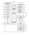
- the main body 100b of the surveying device 100 includes a main body control unit 101, a horizontal drive unit 102, a vertical drive unit 103, a horizontal direction detection unit 104, a vertical direction detection unit 105, a distance measurement unit 106, an operation unit 107, a display unit 108, a telescope unit 109, a memory unit 110, and a tracking unit 111.
- the main body control unit 101 is, for example, a CPU, and includes a survey control unit 101a and a calculation unit 101b.
- the survey control unit 101a of the main body control unit 101 is configured to be able to control the horizontal drive unit 102, the vertical drive unit 103, the horizontal direction detection unit 104, the vertical direction detection unit 105, the distance measurement unit 106, the operation unit 107, the display unit 108, the telescope unit 109, the memory unit 110, the tracking unit 111, and the calculation unit 101b.
- the horizontal drive unit 102 (rotation drive unit) is used to rotate the main body 100b of the surveying device 100 around a vertical axis, i.e., in the horizontal direction.
- the vertical drive unit 103 is used to rotate the telescope unit 109 of the surveying device 100 around a horizontal axis, i.e., in the vertical direction.
- the horizontal direction detection unit 104 is a horizontal encoder capable of detecting the horizontal angle, which is the rotation angle of the telescope unit 109 in the horizontal direction (i.e., the rotation angle from the reference direction DB around the vertical axis).
- the vertical direction detection unit 105 is a vertical encoder capable of detecting the vertical angle, which is the rotation angle of the telescope unit 109 in the vertical direction (i.e., the rotation angle from a reference direction around a horizontal axis).
- the distance measuring unit 106 includes a light transmitting unit for transmitting the distance measuring light L toward the prism 202 of the retroreflective device 200, a light receiving unit for receiving the reflected light from the prism 202, and a calculation unit for calculating the distance between the distance measuring unit 106 and the prism 202 by transmitting and receiving the light.
- the distance measuring light L is, for example, visible light, near infrared light, or ultraviolet light emitted in a linear direction.
- a calculation method for example, a pulse method or a phase difference method, which are well-known technologies, can be adopted.
- the calculation unit 101b of the main body control unit 101 is configured to be able to measure the position of the retroreflective device 200 based on the oblique distance measured by the distance measurement unit 106, the horizontal angle detected by the horizontal direction detection unit 104, and the vertical angle detected by the vertical direction detection unit 105.
- the measurement results can be output, for example, as two-dimensional coordinates (x, y) or three-dimensional coordinates (x, y, z).
- the calculation unit 101b When the calculation unit 101b outputs the measurement results in three-dimensional coordinates, it may output, for example, the position of the prism 202 of the retroreflective device 200 as is, or it may output the three-dimensional coordinates of the measurement point contact point (i.e., the three-dimensional coordinates of measurement point O shown in Figure 1) based on the offset of the prism 202 stored in the memory unit 110 (i.e., the distance between the measurement point contact point at the tip of the pole 201 and the prism 202).
- the operation unit 107 is an operation means that allows an operator to input control instructions to the survey control unit 101a, and includes any device such as a touch panel, switch, button, dial, etc.
- the display unit 108 is for displaying various information, and is configured, for example, with a liquid crystal panel.
- various information refers to any information that has been acquired or can be acquired in the surveying system 1, including surveying results such as the diagonal distance measured by the distance measuring unit 106, the horizontal angle detected by the horizontal direction detection unit 104, the vertical angle detected by the vertical direction detection unit 105, and the position coordinates of the retroreflective device 200 calculated by the calculation unit 101b.
- the display unit 108 may be configured integrally with the operation unit 107.
- the telescope unit 109 is configured so that an operator can visually check the position of the prism 202 through the telescope unit 109.
- the collimation direction of the telescope unit 109 is the same as the emission direction of the distance measurement light L by the distance measurement unit 106.
- the storage unit 110 is realized by a storage medium such as an HDD, SSD, or flash memory, and is configured to be able to store various information such as the dimensions (height, width, depth, etc.) of the surveying device 100, various programs, and surveying results.
- the storage unit 110 stores various information such as the slope distance measured by the distance measurement unit 106, the horizontal angle detected by the horizontal direction detection unit 104, the vertical angle detected by the vertical direction detection unit 105, the surveying results such as the position coordinates of the retroreflective device 200 calculated by the calculation unit 101b, and the offsets mentioned above.
- the tracking unit 111 is a part that irradiates tracking light T and receives the tracking light reflected by the prism 202.
- the survey control unit 101a realizes the tracking function of the retroreflective device 200 by controlling the horizontal drive unit 102 and the vertical drive unit 103 so as to continue to receive the reflected tracking light T.
- the tracking light T is irradiated with a certain width, and the range of this tracking light T is the range in which the prism 202 can be tracked.
- the surveying device 100 can share various information with an information terminal (not shown), and the surveying device 100 can also be controlled by the information terminal.
- information terminals include smartphones, feature phones, tablets, handheld computer devices (examples include PDAs: Personal Digital Assistants), wearable devices (examples include glasses-type devices and watch-type devices), and personal computers.
- the receiving unit 120 of the surveying device 100 is a so-called array antenna, and is equipped with multiple antenna elements 121 capable of receiving radio waves S (S1, S2) transmitted from the transmitting unit 210A of the retroreflective instrument 200.
- the receiving unit 120 has multiple antenna elements 121 arranged in the horizontal and vertical directions (three in the horizontal direction and three in the vertical direction in FIG. 1) on a substrate 122.
- the receiving unit 120 transmits each of the radio waves received by these multiple antenna elements 121 as a signal to the main body control unit 101.
- the retroreflective device 200 comprises a pole 201, a prism 202 (survey object), and a transmitter 210A.
- the end of the pole 201 is placed at measurement point O.
- the prism 202 is a retroreflective part that reflects light in the same direction as the incident light.
- the prism 202 is provided at the upper end of the pole 201, and reflects the distance measurement light L emitted from the distance measurement unit 106 of the main body 100b to the distance measurement unit 106.
- the transmitting unit 210A has a beacon 211A (transmitting terminal) that transmits Bluetooth (registered trademark) radio waves S (S1, S2), a support unit 212A that movably supports the beacon 211A, and a transmission control unit 213A that moves the beacon 211A and transmits the radio waves S (S1, S2) from multiple positions.
- the transmitting unit 210A also has a transmission operation unit (not shown), and can transmit collimation instructions to the surveying device 100 to collimate the prism 202 in response to the operator's operation.
- the transmitter 210A has a beacon 211A provided on a plate-shaped support 212A that extends in one horizontal direction.
- a drive mechanism (not shown) is mounted inside the support 212A, allowing the beacon 211A to slide in the longitudinal direction.
- the transmission control unit 213A is a computer mounted in the support unit 212A, and controls the drive mechanism and the beacon 211A.
- the transmission control unit 213A can control the speed at which the drive mechanism moves the beacon 211A, the movement position, the transmission timing of the radio waves S (S1, S2) from the beacon 211A, etc.
- the distance that the beacon 211A can move on the support part 212A is preferably 0.5 to 2 wavelengths of Bluetooth (registered trademark) radio waves (for example, one wavelength of 2.4 GHz is 12.5 cm) in order to ensure spatial diversity.
- the transmission control part 213A transmits radio waves from the beacon 211A when it is located at a distance of at least 0.5 wavelengths.
- the transmission control part 213A of this embodiment controls the beacon 211A and the support part 212A to transmit radio waves S1 from a first transmission position at one longitudinal end side of the support part 212A and radio waves S2 from a second transmission position at the other longitudinal end side of the support part 212A.
- the surveying device 100 which is the receiving side, has a calculation unit 101b that has a so-called Bluetooth (registered trademark) direction detection function.
- the calculation unit 101b calculates the direction of the transmission unit 210A relative to the receiving unit 120 (the direction of arrival of the signal) based on the phase difference between the signals received by each of the multiple antenna elements 121 of the receiving unit 120.
- This direction of arrival may be a direction in any two-dimensional plane (for example, a horizontal plane) or a direction in three-dimensional space.
- the calculation unit 101b has a function of calculating the direction of arrival of each radio wave S (S1, S2) when the receiving unit 120 receives radio waves S (S1, S2) from the transmitting unit 210A transmitted from multiple different positions.
- the calculation unit 101b is capable of calculating the direction of arrival based on spatial diversity. Then, the calculation unit 101b sets the direction of arrival DA of the main unit 100b from the calculated direction of arrival, and the survey control unit 101a controls the horizontal driving unit 102 so that the main unit 100b is directed to the direction of arrival DA set by the calculation unit 101b.
- the calculation unit 101b calculates the respective arrival directions of the radio waves S1 transmitted by the receiving unit 120 from the first transmission position and the radio waves S2 transmitted from the second transmission position, and then selects one of the arrival directions depending on the radio wave strength. Specifically, the calculation unit 101b selects the arrival direction of the first radio wave S1 or the second radio wave S2, whichever has the stronger radio wave strength, as the final arrival direction, and orients the main unit 100b based on that arrival direction.
- the pointing direction DA of the main body 100b is specifically the horizontal relative direction based on the distance measurement light emission direction of the distance measurement unit 106, i.e., the aiming direction of the telescope unit 109.
- the calculation unit 101b calculates the relative horizontal angle ⁇ from the reference direction DB to the pointing direction DA, and rotates the main body 100b by the relative horizontal angle ⁇ using the horizontal drive unit 102.
- the main body 100b can be directed toward the retroreflective device 200.
- the prism 202 enters the range of the tracking light T, the prism 202 can be aimed by the tracking function using the tracking unit 111.
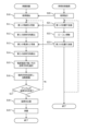
- step S20 on the retroreflective instrument 200 side the transmission control unit 213A issues a collimation instruction to the surveying device 100 based on the operator's operation.
- step S10 on the surveying device 100 side the surveying control unit 101a starts collimation control of the prism 202. Specifically, the surveying control unit 101a starts irradiating the tracking light T from the tracking unit 111.
- the transmission control unit 213A causes the beacon 211A to transmit radio waves (first radio waves S1) at a first position on the support unit 212A.
- the receiver 120 receives the first radio wave S1. Specifically, each antenna element 121 of the receiver 120 receives the first radio wave S1 and measures the radio wave intensity and phase.
- step S12 on the surveying device 100 side the calculation unit 101b calculates the direction of arrival of the first radio wave S1 (first direction of arrival) from the phase difference measured by each antenna element 121.
- the transmission control unit 213A moves the beacon 211A. Specifically, the transmission control unit 213A controls the drive mechanism in the support unit 212A to slide the beacon 211A and move it to the second position. Note that in step S22, instead of sliding the beacon 211A by controlling the drive mechanism, the beacon 211A may be manually slid by an operator.
- step S23 on the retroreflective device 200 side the transmission control unit 213A transmits radio waves (second radio waves S2) from the beacon 211A at a second position on the support unit 212A.
- the receiver 120 receives the second radio wave S2. Specifically, each antenna element 121 of the receiver 120 receives the second radio wave S2 and measures the radio wave intensity and phase.
- step S14 on the surveying device 100 side the calculation unit 101b calculates the arrival direction of the second radio wave S2 (second arrival direction) from the phase difference measured by each antenna element 121.
- step S15 on the surveying device 100 side the calculation unit 101b selects the arrival direction calculated based on the radio wave with the stronger radio wave intensity between the first radio wave S1 and the second radio wave S2 as the final arrival direction.
- step S16 on the surveying device 100 side the calculation unit 101b sets the direction of arrival selected in step S15 as the direction of orientation DA, and the surveying control unit 101a rotates the main body unit 100b using the horizontal drive unit 102. Specifically, the calculation unit 101b calculates the relative horizontal angle ⁇ from the reference direction DB to the direction of orientation DA, and the surveying control unit 101a rotates the main body unit 100b by the relative horizontal angle ⁇ .
- step S17 on the surveying device 100 side the surveying control unit 101a judges whether or not the tracking light T is reflected by the prism 202 after the rotation drive of the main body unit 100b has stopped. If step S17 is Yes, that is, if the tracking light T is reflected by the prism 202, it means that the prism 202 has entered the tracking light T, and the surveying control unit 101a proceeds to step S18. Specifically, in step S18, the surveying control unit 101a collimates the prism 202 using the reflected light of the tracking light T. On the other hand, if step S17 is No, that is, if the prism 202 does not enter the tracking light T even after the rotation drive for the relative horizontal angle ⁇ has ended, the process may return to steps S11 and S21.
- step S19 on the surveying device 100 side the surveying control unit 101a performs surveying of the prism 202. That is, the surveying control unit 101a measures the diagonal distance using the distance measurement unit 106, detects the horizontal angle using the horizontal direction detection unit 104, and detects the vertical angle using the vertical direction detection unit 105, and outputs the surveying results.
- the main body control unit 101 and the transmission control unit 213A end the routine.
- the calculation unit 101b calculates the direction of arrival of each radio wave, sets the direction of orientation DA from each direction of arrival, and rotates the main body 100b toward the direction of orientation DA.
- the main body 100b can be directed to the retroreflective instrument 200 even in a range where the tracking function of the tracking unit 111 does not reach, and by calculating the direction of arrival from the radio waves S (S1, S2) transmitted from a plurality of positions, the effect of multipath can be suppressed by utilizing spatial diversity, and the direction of arrival of the radio waves S (S1, S2) can be recognized more accurately.
- the receiving unit 120 is an array antenna having multiple antenna elements 121, and the calculation unit 101b calculates the direction of arrival from the phase difference of the radio waves received by each antenna element 121, so that it can easily recognize the direction of arrival of the radio waves S (S1, S2).
- the transmission unit 210A provided on the retroreflective device 200 has the beacon 211A movably mounted on the support unit 212A, and the transmission control unit 213A moves the beacon 211A to transmit the radio waves from multiple positions, easily achieving spatial diversity. This also makes it possible to suppress the effects of multipath and more accurately recognize the direction of arrival of the radio waves S (S1, S2).
- the surveying device 100 and the retroreflective device 200 are complementary to each other in order to realize spatial diversity, and the surveying system 1 having the surveying device 100 and the retroreflective device 200 can also suppress the effects of multipath and more accurately recognize the direction of arrival of the radio waves S (S1, S2).
- the calculation unit 101b selects the direction of arrival based on the radio wave with the stronger radio wave strength (S1 or S2) as the final direction of arrival, and sets the directional direction DA.
- This has the advantage of being able to eliminate directions of arrival based on radio waves with weaker radio wave strength (S1 or S2), i.e., radio waves (S1 or S2) that are likely to be less accurate.
- the method of calculating the final direction of arrival is not limited to this.
- the calculation unit 101b may combine radio waves (S1 and S2) transmitted from multiple positions to set the final arrival direction (i.e., the pointing direction DA). Specifically, the calculation unit 101b may average the calculated arrival angles (angles to the arrival direction with respect to the reference direction DB) of each radio wave (S1 and S2) to determine the final arrival direction. In addition to simple averaging, the calculation unit 101b may also weight the radio waves S1 and S2 according to their strength, and then average them. In other words, a combination process is performed that increases the proportion of arrival directions with high radio wave strength.
- the transmitter 210A is capable of transmitting radio waves S (S1, S2) from multiple positions by the beacon 211A sliding horizontally, but the configuration of the transmitter is not limited to this.
- the transmitter 210B of the first modified example shown in FIG. 4A has a plate-like support 212B extending along the longitudinal direction of the pole 201 of the retroreflective instrument 200.
- the beacon 211B can slide along the support 212B, i.e., along the longitudinal direction of the pole 201. Therefore, when the retroreflective instrument 200 is installed, the beacon 211B moves vertically. Being able to transmit radio waves from multiple positions in the vertical direction makes it possible to achieve spatial diversity with reduced error in relation to the horizontal angle, which is more suitable for directing the main body 100b of the surveying device 100 to the retroreflective instrument 200.
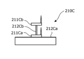
- the transmitter 210C of the second modified example shown in FIG. 4B is attached to the top end of the pole 201 as in the above embodiment, but a column 212Cb is also erected on the support 212Ca.
- a first beacon 211Ca is provided at the bottom of the column 212Cb, and a second beacon 211Cb is provided at the top of the column 212Cb.
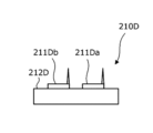
- the transmitter 210D of the third modified example shown in FIG. 4C is attached to the top end of the pole 201 in the same manner as in the above embodiment, with a first beacon 211Da provided at a first position on one end of the support 212D and a second beacon 211Db provided at a second position on the other end of the support 212D.
- radio waves can be transmitted from the first and second positions, making it possible to easily achieve spatial diversity without requiring a drive mechanism.
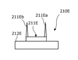
- the transmitter 210E of the fourth modified example shown in FIG. 4D is attached at the top end of the pole 201, as in the above embodiment, and a long beacon 211E is provided on and along a support 212E.
- the beacon 211E has a first transmitting antenna 211Ea at a first position on one end, and a second transmitting antenna 211Eb at a second position on the other end.
- a transmission control unit (not shown) switches between the first transmitting antenna 211Ea and the second transmitting antenna 211Eb to transmit radio waves.
- the transmitter may be configured by combining the above embodiments and each of the modified examples.
- each of the beacons in the above embodiments and the first to third modified examples may be provided with multiple antennas, as in the beacon 211E of the fourth modified example.
- a drive mechanism may be provided in the support part of the second to fourth modified examples, allowing each beacon to slide on the support part.
- the movement direction of the beacon is horizontal in the above embodiment and vertical in the first modified example, but is not limited to this as long as the angle of arrival as seen from the receiver 120 does not change significantly.
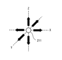
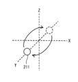
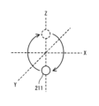
- Figs. 5A to 5D show explanatory diagrams showing the movement direction of the beacon. Note that in Fig. 5, the XY plane is the horizontal direction, the Z axis is the vertical direction, the circle indicates the position of the beacon, and the arrow indicates the movement direction.
- the beacon 211 may be freely moved linearly in multiple directions, rather than just reciprocating in one horizontal direction and one vertical direction as in the above embodiment and the first modified example. Also, the beacon 211 may be rotated around the X-axis as shown in FIG. 5B, the beacon 211 may be rotated around the Y-axis as shown in FIG. 5C, or the beacon 211 may be rotated around the Z-axis as shown in FIG. 5D.
- the relative positional relationship is not limited to the horizontal or vertical direction, but may be arranged three-dimensionally with horizontal and vertical spacing.
- arranging the beacons three-dimensionally with respect to the receiving unit 120 ensures greater diversity and allows for appropriate spatial diversity to be achieved.
- the pointing direction DA is set by the calculation unit 101b by calculating the relative horizontal angle ⁇ , but the pointing direction is not limited to the horizontal angle alone, and it is also possible to set the vertical angle alone, or both the horizontal angle and the vertical angle.
- each of the multiple receivers 120 receives radio waves S (S1, S2) transmitted from multiple positions and calculates the direction of arrival of the radio waves S.
- the calculation unit 101b recognizes the direction of arrival calculated by the receiver 120 that received the stronger radio waves S (S1, S2) among the directions of arrival calculated for each of the multiple receivers 120 as the final direction of arrival (direction of direction DA), or recognizes the direction of arrival calculated for each of the multiple receivers 120 after performing a synthesis process such as averaging, as the final direction of arrival (direction of direction DA).
- spatial diversity is also utilized on the receiving side of the radio waves S, so that the effect of multipath can be further suppressed and the direction of arrival of the radio waves S (direction of direction DA) can be recognized more accurately.
- a rotation drive unit capable of rotating the main body unit;
- a receiving unit that receives a specific radio wave;
- a calculation unit that calculates an arrival direction of each radio wave when the receiving unit receives the radio waves transmitted from a plurality of different positions, and sets a directivity direction of the main unit from each arrival direction;
- a drive control unit that controls the rotation drive unit so as to orient the main body unit in a direction set by the calculation unit;
- a receiving device comprising: [2] the receiving unit is an array antenna having a plurality of antenna elements, The receiving device according to [1] above, wherein the calculation unit calculates the direction of arrival from a phase difference of the radio waves received by each of the antenna elements.
- a transmitting terminal that transmits a specific radio wave; a support section that movably supports the transmitting terminal; a transmission control unit that moves the transmitting terminal and transmits the radio waves from a plurality of positions;
- a transmitting device comprising: [7] A transmitting terminal that transmits a specific radio wave; A support part on which the plurality of transmitting terminals are arranged at different positions; a transmission control unit that causes each of the plurality of transmitting terminals to transmit the radio waves;
- a transmitting device comprising: [8] The transmitting device according to [6] or [7] above, further comprising a retroreflection section connected to the support section and reflecting light in the same direction as the incident direction. [9] A receiving device according to the above [1], [2], [3], [4] or [5]; A transmitting device according to the above [6], [7] or [8],
- a transmitting and receiving system comprising:
- Survey system (transmitting and receiving system) 100
- Surveying equipment (receiving device) 100a: Tripod 100b: Main body 101: Main body control unit 101a: Survey control unit 101b: Calculation unit 102: Horizontal drive unit (rotation drive unit) 103 Vertical driving unit 104 Horizontal direction detection unit 105 Vertical direction detection unit 106 Distance measurement unit 107 Operation unit 108 Display unit 109 Telescope unit 110 Memory unit 111 Tracking unit 120 Receiving unit 121 Antenna element 200 Retroreflection device (transmitting device) 201 Pole 202 Prism 210A to 210E Transmitting section 211 (211A to 211E) Beacon (transmitting terminal) 212 (212A to 212E Support part DA Orientation direction DB Reference direction L Ranging light O Measurement point S (S1, S2) Radio wave T Tracking light ⁇ Relative horizontal angle
Landscapes
- Physics & Mathematics (AREA)
- Engineering & Computer Science (AREA)
- General Physics & Mathematics (AREA)
- Radar, Positioning & Navigation (AREA)
- Remote Sensing (AREA)
- Position Fixing By Use Of Radio Waves (AREA)
Abstract
測量システム1は、測量装置100と、送信部210Aが設けられた再帰反射器具200とを有し、測量装置100は、本体部100bを鉛直軸回りに回転可能な水平駆動部102と、特定の電波を受信する受信部120と、受信部が異なる複数の位置から送信された電波を受信した場合に、各電波の推定到来方向を算出して各推定到来方向から本体部の指向方向を設定する演算部101bと、演算部により設定された指向方向に本体部を指向させるよう水平駆動部を制御する測量制御部101aと、を備え、送信部210Aは、特定の電波を送信するビーコン211Aと、ビーコンを移動可能に支持する支持部212Aと、ビーコンを移動させ複数の位置から電波を送信させる送信制御部213Aと、を備える。
Description
本開示は、受信装置、送信装置、及び送受信システムに関するものである。
近年、Bluetooth(登録商標)の電波が送信された方向を認識可能な方向検知技術が普及している。例えば下記特許文献1では、Bluetooth(登録商標)の方向検知技術を測量装置に適用して、測量装置を測量対象に指向させることを可能としている。
特許文献1では、反射等の影響で本来の方向とは異なる方向からの電波も受信される現象(いわゆるマルチパス)が発生し、電波の到来方向を正確に検知できない場合がある。
そこで、本開示の目的は、マルチパスの影響を抑制し、より正確に電波の到来方向を認識できる受信装置、送信装置、及び送受信システムを提供することにある。
上記した目的を達成するために、本開示の受信装置は、本体部を回転可能な回転駆動部と、特定の電波を受信する受信部と、前記受信部が異なる複数の位置から送信された前記電波を受信した場合に、各電波の到来方向を算出して、各到来方向から前記本体部の指向方向を設定する演算部と、前記演算部により設定された指向方向に前記本体部を指向させるよう前記回転駆動部を制御する駆動制御部と、を備える。
また本開示の送信装置は、特定の電波を送信する送信端末と、前記送信端末を移動可能に支持する支持部と、前記送信端末を移動させ複数の位置から前記電波を送信させる送信制御部と、を備える。
また本開示の送信装置は、特定の電波を送信する送信端末と、複数の前記送信端末が異なる複数の位置に配設された支持部と、複数の前記送信端末からそれぞれ前記電波を送信させる送信制御部と、を備える。
本開示の送受信システムは、上記受信装置と、上記送信装置のいずれかとを備える。
上記本開示によれば、マルチパスの影響を抑制し、より正確に電波の到来方向を認識できる。
次に、図1~図5を適宜参照しつつ、本開示に係る受信装置及び送信装置を適用した測量システム(送受信システム)の一実施形態について説明する。
(測量システムの構成)
図1に示す測量システム1は、例えば建設現場において、測量装置100により、作業者が設置した再帰反射器具200の位置を測量するシステムである。測量システム1は、本開示に係る送受信システムの一実施形態である。
図1に示す測量システム1は、例えば建設現場において、測量装置100により、作業者が設置した再帰反射器具200の位置を測量するシステムである。測量システム1は、本開示に係る送受信システムの一実施形態である。
図1に示すように、測量システム1は、測量装置100と、再帰反射器具200とを備えている。測量装置100は、例えばモータドライブ(MD)を有するトータルステーション(TS)であり、三脚100aと、三脚100aに支持されている円筒状の本体部100bと、本体部100bの上部に設けられている受信部120とを備えている。測量装置100は、本開示に係る受信装置の一実施形態である。再帰反射器具200は、本開示に係る送信装置の一実施形態である。
図2に示すように、測量装置100の本体部100bは、本体制御部101と、水平駆動部102と、鉛直駆動部103と、水平方向検出部104と、鉛直方向検出部105と、測距部106と、操作部107と、表示部108と、望遠鏡部109と、記憶部110と、追尾部111とを備えている。また、本体制御部101は、例えばCPUであり、測量制御部101aと演算部101bとを備えている。
本体制御部101の測量制御部101aは、水平駆動部102と、鉛直駆動部103と、水平方向検出部104と、鉛直方向検出部105と、測距部106と、操作部107と、表示部108と、望遠鏡部109と、記憶部110と、追尾部111と、演算部101bとを制御可能に構成されている。
水平駆動部102(回転駆動部)は、測量装置100の本体部100bを鉛直軸回り、即ち水平方向に回転させるためのものである。
鉛直駆動部103は、測量装置100の望遠鏡部109を水平軸回り、即ち鉛直方向に回転させるためのものである。
水平方向検出部104は、望遠鏡部109の水平方向における回転角である水平角(すなわち、鉛直軸回りにおける基準方向DBからの回転角)を検出可能な水平エンコーダである。
鉛直方向検出部105は、望遠鏡部109の鉛直方向における回転角である鉛直角(すなわち、水平軸回りにおける基準方向からの回転角)を検出可能な鉛直エンコーダである。
測距部106は、測距光Lを再帰反射器具200のプリズム202に向かって送光するための送光部と、プリズム202からの反射光を受光するための受光部と、これら送光及び受光によって測距部106とプリズム202との距離を算出する算出部とを備えている。測距光Lは、例えば、直線方向に出射される可視光、近赤外線又は紫外線である。算出方式(測距方式)としては、例えば、周知の技術であるパルス方式又は位相差方式を採用することができる。
本体制御部101の演算部101bは、測距部106により測定された斜距離と、水平方向検出部104により検出された水平角と、鉛直方向検出部105により検出された鉛直角とに基づき、再帰反射器具200の位置を測定可能に構成されている。この測定結果としては、例えば、2次元座標(x、y)又は3次元座標(x、y、z)として出力することができる。
演算部101bは、この測定結果を3次元座標で出力する場合、例えば、再帰反射器具200のプリズム202の位置をそのまま出力してもよく、記憶部110において記憶されているプリズム202のオフセット(つまり、ポール201の先端の測点接触箇所とプリズム202との距離)に基づいて、この測点接触箇所の3次元座標(つまり図1に示す測点Оの3次元座標)を出力してもよい。
操作部107は、作業者が測量制御部101aに制御指示を与える入力を実施可能な操作手段であり、例えば、タッチパネル、スイッチ、ボタン、ダイアル等の任意のデバイスを含んでいる。
表示部108は、各種情報を表示するためのものであり、例えば液晶パネルにより構成されている。本明細書において、各種情報とは、測距部106により測定された斜距離、水平方向検出部104により検出された水平角、鉛直方向検出部105により検出された鉛直角、演算部101bにより算出された再帰反射器具200の位置座標等の測量結果を含む、測量システム1において取得済み又は取得可能なあらゆる情報である。表示部108は、操作部107と一体に構成されていてもよい。
望遠鏡部109は、作業者が望遠鏡部109を介してプリズム202の位置を視認可能なように構成されている。望遠鏡部109の視準方向は、測距部106による測距光Lの出射方向と同一方向になっている。
記憶部110は、例えば、HDD、SSD又はフラッシュメモリ等の記憶媒体により実現され、測量装置100の寸法(高さ、幅、奥行きなど)、各種プログラム、測量結果等の各種情報を記憶可能に構成されている。例えば、記憶部110は、測距部106により測定された斜距離、水平方向検出部104により検出された水平角、鉛直方向検出部105により検出された鉛直角、演算部101bにより算出された再帰反射器具200の位置座標等の測量結果、上記オフセット等の各種情報を記憶している。
追尾部111は、追尾光Tを照射し、プリズム202により反射された追尾光を受光する部分である。測量制御部101aは、反射された追尾光Tを受光し続けるよう水平駆動部102及び鉛直駆動部103を制御することで再帰反射器具200の追尾機能を実現している。なお図1に示すように追尾光Tはある程度幅を有して照射され、この追尾光Tの範囲がプリズム202を追尾可能な範囲となる。
また図示しないが、測量装置100は、図示しない情報端末との間で各種情報を共有可能であり、情報端末により測量装置100を制御することも可能である。情報端末としては、例えば、スマートフォン、フィーチャーフォン、タブレット、ハンドヘルドコンピュータデバイス(一例として、PDA:Personal Digital Assistant)、ウェアラブル端末(一例として、メガネ型デバイス、時計型デバイス)、パーソナルコンピュータ等がある。
測量装置100の受信部120は、いわゆるアレイアンテナであり、再帰反射器具200の送信部210Aから送信される電波S(S1、S2)を受信可能な複数のアンテナ素子121を備えている。具体的には、図1に示すように受信部120は基板122上にアンテナ素子121が水平方向及び鉛直方向にそれぞれ複数(図1では水平方向3つずつ、鉛直方向3つずつ)配設されている。受信部120はこれら複数のアンテナ素子121で受信した各電波を信号として本体制御部101に送信する。
再帰反射器具200は、ポール201と、プリズム202(測量対象)と、送信部210Aとを備えている。測量時には、ポール201の端部が測点Оに設置される。プリズム202は、入射した光と同じ方向に光を反射する再帰反射部である。プリズム202は、ポール201の上端に設けられており、本体部100bの測距部106から出射される測距光Lを測距部106に反射させる。
送信部210Aは、Bluetooth(登録商標)の電波S(S1、S2)を送信するビーコン211A(送信端末)と、当該ビーコン211Aを移動可能に支持する支持部212Aと、ビーコン211Aを移動させ複数の位置から電波S(S1、S2)を送信させる送信制御部213Aと、を有している。また送信部210Aは、図示しない送信操作部を有しており、作業者の操作に応じて測量装置100に対して、プリズム202を視準させる視準指示を送信することも可能である。
詳しくは、図1に示すように、送信部210Aは、水平方向の一方向の延びた板状の支持部212A上に、ビーコン211Aが設けられている。支持部212A内には図示しない駆動機構が搭載され、ビーコン211Aを長手方向に摺動可能である。
送信制御部213Aは、支持部212A内に搭載されたコンピュータであり、駆動機構の制御及びビーコン211Aの制御を行う。例えば、送信制御部213Aは、駆動機構によるビーコン211Aの移動速度や、移動位置、ビーコン211Aからの電波S(S1、S2)の送信タイミング等を制御可能である。
なお、ビーコン211Aが支持部212A上で移動可能な距離、即ち支持部212Aの長手方向長さは、空間ダイバーシティを確保するため、Bluetooth(登録商標)の電波の0.5波長から2波長分の長さ(例えば2.4GHzの1波長12.5cm)が好ましい。送信制御部213Aは、少なくとも0.5波長分離れた位置にあるときにビーコン211Aからの電波送信を行う。例えば本実施形態の送信制御部213Aは、ビーコン211A及び支持部212Aを制御して、支持部212Aの長手方向一端側の第1の送信位置からの電波S1と、支持部212Aの長手方向他端側の第2の送信位置からの電波S2と、を送信させる。
一方、受信側である測量装置100は、演算部101bがいわゆるBluetooth(登録商標)の方向検出機能を有する。具体的には、演算部101bは受信部120の複数のアンテナ素子121それぞれが受信した信号間の位相差に基づき、受信部120に対する送信部210Aの方向(信号の到来方向)を算出する。この到来方向は、任意の2次元平面における方向(例えば水平面)であっても3次元空間における方向であってもよい。
さらに演算部101bは、受信部120が異なる複数の位置から送信された送信部210Aからの電波S(S1、S2)を受信した場合に、各電波S(S1、S2)の到来方向を算出する機能を有する。つまり、演算部101bは、空間ダイバーシティに基づく到来方向の算出が可能である。そして、演算部101bは、算出した到来方向から本体部100bの指向方向DAを設定し、測量制御部101aが演算部101bにより設定された指向方向DAに本体部100bを指向させるよう水平駆動部102を制御する。
例えば、演算部101bは、受信部120によって第1の送信位置から送信された電波S1と、第2の送信位置から送信された電波S2のそれぞれの到来方向を算出した後、電波強度に応じていずれかの到来方向を選択する。具体的には、演算部101bは、第1の電波S1と第2の電波S2のうち電波強度の強い方の到来方向を最終的な到来方向として選択し、当該到来方向に基づいて本体部100bを指向させる。
本体部100bの指向方向DAは、具体的には測距部106の測距光出射方向、即ち望遠鏡部109の視準方向を基準とした水平方向の相対向きである。演算部101bは基準方向DBから指向方向DAまでの相対水平角θを算出して、当該相対水平角θ分、水平駆動部102により本体部100bを回転させる。このように本体部100bを指向方向DAに指向させることで、本体部100bを再帰反射器具200に向かせることができる。そして、プリズム202が追尾光Tの範囲内に入った際には、追尾部111を用いた追尾機能によりプリズム202を視準できる。
(測量方法の手順)
次に、本実施形態の測量システム1を用いた測量方法について、図3のフローチャートに沿って説明する。なお、本フローチャートは、前提として作業者が再帰反射器具200を測点Oに設置しており、且つプリズム202が追尾光Tの範囲外にある場合の測量制御を示している。
次に、本実施形態の測量システム1を用いた測量方法について、図3のフローチャートに沿って説明する。なお、本フローチャートは、前提として作業者が再帰反射器具200を測点Oに設置しており、且つプリズム202が追尾光Tの範囲外にある場合の測量制御を示している。
まず、再帰反射器具200側のステップS20において、送信制御部213Aは、作業者の操作に基づき測量装置100に対して視準指示する。
測量装置100側のステップS10において、測量制御部101aは、プリズム202の視準制御を開始する。具体的には、測量制御部101aは、追尾部111から追尾光Tの照射を開始する。
次に再帰反射器具200側のステップS21において、送信制御部213Aは、支持部212A上の第1の位置にてビーコン211Aから電波(第1の電波S1)を送信させる。
測量装置100側のステップS11において、受信部120が第1の電波S1を受信する。具体的には受信部120の各アンテナ素子121がそれぞれ第1の電波S1を受信し、電波強度や位相を測定する。
続いて、測量装置100側のステップS12において、演算部101bは、各アンテナ素子121が測定した位相差から第1の電波S1の到来方向(第1の到来方向)を算出する。
一方、再帰反射器具200側のステップS22において、送信制御部213Aは、ビーコン211Aを移動させる。具体的には、送信制御部213Aは、支持部212A内の駆動機構を制御してビーコン211Aを摺動させて第2の位置まで移動させる。なお、ステップS22においては、駆動機構の制御によりビーコン211Aを摺動させることに代えて、作業者の手動によりビーコン211Aを摺動させてもよい。
再帰反射器具200側のステップS23において、送信制御部213Aは、支持部212A上の第2の位置にてビーコン211Aから電波(第2の電波S2)を送信する。
測量装置100側のステップS13において、受信部120が第2の電波S2を受信する。具体的には受信部120の各アンテナ素子121がそれぞれ第2の電波S2を受信し、電波強度や位相を測定する。
続いて、測量装置100側のステップS14において、演算部101bは、各アンテナ素子121が測定した位相の差から第2の電波S2の到来方向(第2の到来方向)を算出する。
測量装置100側のステップS15において、演算部101bは、第1の電波S1及び第2の電波S2のうち、電波強度の強い方の電波に基づき算出された到来方向を、最終的な到来方向として選択する。
測量装置100側のステップS16において、演算部101bがステップS15にて選択した到来方向を指向方向DAとして設定し、測量制御部101aが水平駆動部102により本体部100bを回転駆動させる。具体的には、演算部101bは、基準方向DBから指向方向DAまでの相対水平角θを算出して、測量制御部101aが当該相対水平角θ分、本体部100bを回転駆動させる。
測量装置100側のステップS17において、測量制御部101aは、本体部100bの回転駆動停止後に、追尾光Tがプリズム202により反射されているか否かを判断する。ステップS17がYesである場合、すなわち、追尾光Tがプリズム202により反射された場合、プリズム202が追尾光T内に入ったことを意味し、測量制御部101aはステップS18に処理を進める。具体的には、ステップS18において、測量制御部101aは、追尾光Tの反射光を用いてプリズム202を視準する。一方、ステップS17がNoである場合、すなわち、相対水平角θ分の回転駆動が終了してもプリズム202が追尾光T内に入らない場合には、上記ステップS11及びステップS21に戻ってもよい。
ステップS18の実施後、測量装置100側のステップS19において、測量制御部101aはプリズム202の測量を実行する。つまり、測量制御部101aは、測距部106による斜距離の測定、水平方向検出部104による水平角の検出、鉛直方向検出部105による鉛直角の検出を行い、測量結果を出力する。測量結果の出力が完了すると、本体制御部101及び送信制御部213Aは当該ルーチンを終了する。
(本実施形態の効果)
上記実施形態に係る測量システム1及び測量方法によれば、測量装置100は、受信部120が異なる複数の位置から送信された電波を受信した場合に、演算部101bが各電波の到来方向を算出し、各到来方向から指向方向DAを設定し、指向方向DAに向けて本体部100bを回転駆動させている。このように電波による位置検出技術を用いて、送信部210Aが設けられた再帰反射器具200の位置を特定することで、追尾部111による追尾機能が及ばない範囲でも、本体部100bを再帰反射器具200に指向させることができ、且つ複数の位置から送信された電波S(S1、S2)から到来方向を算出することで、空間ダイバーシティを利用してマルチパスの影響を抑制し、より正確に電波S(S1、S2)の到来方向を認識できる。
上記実施形態に係る測量システム1及び測量方法によれば、測量装置100は、受信部120が異なる複数の位置から送信された電波を受信した場合に、演算部101bが各電波の到来方向を算出し、各到来方向から指向方向DAを設定し、指向方向DAに向けて本体部100bを回転駆動させている。このように電波による位置検出技術を用いて、送信部210Aが設けられた再帰反射器具200の位置を特定することで、追尾部111による追尾機能が及ばない範囲でも、本体部100bを再帰反射器具200に指向させることができ、且つ複数の位置から送信された電波S(S1、S2)から到来方向を算出することで、空間ダイバーシティを利用してマルチパスの影響を抑制し、より正確に電波S(S1、S2)の到来方向を認識できる。
特に受信部120は複数のアンテナ素子121を有するアレイアンテナであり、演算部101bは、各アンテナ素子121で受信した電波の位相差から到来方向を算出することから、容易に電波S(S1、S2)の到来方向を認識することができる。
また、再帰反射器具200に設けられた送信部210Aは、ビーコン211Aが移動可能に支持部212Aに設けられ、送信制御部213Aがビーコン211Aを移動させ複数の位置から前記電波を送信させることで、容易に空間ダイバーシティを実現させることができる。これによっても、マルチパスの影響を抑制し、より正確に電波S(S1、S2)の到来方向を認識させることできる。
測量装置100と再帰反射器具200は、空間ダイバーシティを実現するために相補的に関連しており、これら測量装置100と再帰反射器具200を有する測量システム1としても、マルチパスの影響を抑制し、より正確に電波S(S1、S2)の到来方向を認識させることできる。
(その他の実施形態)
以上で本開示の一実施形態の説明を終えるが、本開示の態様はこの実施形態に限定されるものではない。
以上で本開示の一実施形態の説明を終えるが、本開示の態様はこの実施形態に限定されるものではない。
上記実施形態では、演算部101bは電波強度の強い方の電波(S1又はS2)に基づく到来方向を最終的な到来方向として選択し、指向方向DAを設定している。これにより電波強度が弱い電波(S1又はS2)、つまり精度が低い可能性が高い電波(S1又はS2)に基づく到来方向を排除することができるという利点がある。一方、最終的な到来方向の算出方法はこれに限られるものではない。
例えば、演算部101bは、複数の位置から送信された電波(S1及びS2)を合成して、最終的な到来方向(つまり指向方向DA)を設定してもよい。具体的には、演算部101bは、算出した各電波(S1及びS2)の到来角(基準方向DBに対する到来方向までの角度)を平均化して最終的な到来方向としてもよい。単純な平均化だけでなく、例えば各電波S1、S2の強度に応じて重みづけした上で平均化をしてもよい。つまり電波強度の高い到来方向に寄る割合が高くなる合成処理を行う。
このように、算出した各到来方向を合成処理して指向方向DAを設定すれば、極端に精度を落とすことなく、電波S(S1、S2)の到来方向を認識させることできる。
また、上記実施形態では、送信部210Aは、ビーコン211Aが水平方向に摺動することで、複数の位置から電波S(S1、S2)を送信可能としているが、送信部の構成はこれに限られるものではない。
ここで図4A~図4Dを参照すると、送信部の変形例を示す説明図が示されており、以下同図に基づき送信部の変形例について説明する。なお、各変形例において、支持部内に設けられている送信制御部は図示を省略している。
図4Aに示す第1変形例の送信部210Bは、支持部212Bが再帰反射器具200のポール201の長手方向に沿って延びた板状をなしている。ビーコン211Bは当該支持部212Bに沿って、即ちポール201の長手方向に沿って摺動可能である。したがって、再帰反射器具200を設置すると、ビーコン211Bは鉛直方向に移動することとなる。鉛直方向の複数位置から電波を送信できることで、水平角に対する誤差を抑えた空間ダイバーシティを実現することが可能となり、測量装置100の本体部100bを再帰反射器具200に指向させるのに、より好適である。
図4Bに示す第2変形例の送信部210Cは、取付位置は上記実施形態と同じようにポール201の上端であるが、支持部212Ca上にさらに柱部212Cbが立設している。そして、柱部212Cb下部に第1ビーコン211Caが設けられ、柱部212Cb上部に第2ビーコン211Cbが設けられている。このような構成によっても、鉛直方向の複数位置から電波を送信できる。したがって、第1変形例と同様に、水平角に対する誤差を抑えた空間ダイバーシティを実現することが可能となり、測量装置100の本体部100bを再帰反射器具200に指向させるのに、より好適である。
図4Cに示す第3変形例の送信部210Dは、取付位置は上記実施形態と同じようにポール201の上端であり、支持部212Dの一端側の第1の位置に第1ビーコン211Daが設けられ、支持部212Dの他端側の第2の位置に第2ビーコン211Dbが設けられている。このような構成によっても第1の位置及び第2の位置から電波を送信でき、駆動機構を要さずに容易に空間ダイバーシティを実現することができる。
図4Dに示す第4変形例の送信部210Eは、取付位置は上記実施形態と同じようにポール201の上端であり、支持部212E上に、当該支持部212Eに沿って長いビーコン211Eが設けられている。当該ビーコン211Eは、一端側の第1の位置に第1送信アンテナ211Eaを有し、他端側の第2の位置に第2送信アンテナ211Ebを有している。図示しない送信制御部は、第1送信アンテナ211Ea及び第2送信アンテナ211Ebを切り替えて電波を送信する。このような構成によっても第1の位置及び第2の位置から電波を送信でき、駆動機構を要さずに容易に空間ダイバーシティを実現することができる。
なお、送信部は上記実施形態及び各変形例を組み合わせた構成としてもよい。例えば、上記実施形態及び第1~第3変形例の各ビーコンに、第4変形例のビーコン211Eのように複数のアンテナを設けてもよい。また、第2~第4変形例の支持部に駆動機構を設けて各ビーコンを支持部上にて摺動可能としてもよい。
また、ビーコンの移動方向は、上記実施形態では水平方向、第1変形例では鉛直方向であるが、受信部120から見た到来角が大きく変化しない範囲であれば、これに限られるものではない。例えば、図5A~図5Dにはビーコンの移動方向を示す説明図が示されている。なお図5ではXY平面を水平方向とし、Z軸を鉛直方向として、丸印がビーコンの位置を示し、矢印により移動方向を示している。
図5Aに示すように、上記実施形態や第1変形例のような水平方向の一方向、鉛直方向一方向に往復運動させるだけでなく、ビーコン211を直線的に多方向に自由に移動させてもよい。また、図5Bに示すようにビーコン211をX軸線周りに回転移動させたり、図5Cに示すようようにビーコン211をY軸線回りに回転移動させたり、図5Dに示すようにビーコン211をZ軸線周りに回転移動させたり、してもよい。
また、図示しないが、第2変形例や第3変形例のように複数のビーコンを配置する場合も、相対的な位置関係は水平方向や鉛直方向に限られず、水平方向且つ鉛直方向に離間した三次元的な配置にしてもよい。特に受信部120に対して三次元的に位置をずらして配置するとより多様性が確保され、適切な空間ダイバーシティを実現することができる。
また、上記実施形態における演算部101bによる指向方向DAの設定は、相対水平角θを算出することで行っているが、指向方向は水平角のみに限られず、鉛直角のみ、又は水平角及び鉛直角の両方を設定してもよい。
上記実施形態では測量装置100に対して単数の受信部120のみが設けられているが、測量装置100に対して複数の受信部120が設けられていてもよい。この場合、複数の受信部120のそれぞれが、複数の位置から送信された電波S(S1、S2)を受信して電波Sの到来方向を算出する。 演算部101bは、例えば、複数の受信部120ごとに算出した上記到来方向のうち、より強い電波S(S1、S2)を受信した受信部120により算出した上記到来方向を最終的な到来方向(指向方向DA)として認識するか、または、複数の受信部120ごとに算出した上記到来方向に平均化等の合成処理を行った上記到来方向を最終的な到来方向(指向方向DA)として認識する。これにより、電波Sの受信側においても空間ダイバーシティを利用するため、マルチパスの影響をさらに抑制することができ、より正確に電波Sの到来方向(指向方向DA)を認識することができる。
本開示に係る発明の技術的特徴を抽出すると例えば以下のようになる。
[1]
本体部を回転可能な回転駆動部と、
特定の電波を受信する受信部と、
前記受信部が異なる複数の位置から送信された前記電波を受信した場合に、各電波の到来方向を算出して、各到来方向から前記本体部の指向方向を設定する演算部と、
前記演算部により設定された指向方向に前記本体部を指向させるよう前記回転駆動部を制御する駆動制御部と、
を備える受信装置。
[2]
前記受信部は複数のアンテナ素子を有するアレイアンテナであり、
前記演算部は、前記各アンテナ素子で受信した前記電波の位相差から前記到来方向を算出する、上記[1]に記載の受信装置。
[3]
前記演算部は、前記複数の位置から送信された電波のうち、強度の強い電波から推定された到来方向を前記指向方向に設定する、上記[1]又は[2]に記載の受信装置。
[4]
前記演算部は、前記複数の位置から送信された電波を合成処理して前記指向方向を設定する、上記[1]、[2]又は[3]に記載の受信装置。
[5]
前記本体部は、測量対象を測量するための測距部をさらに備える、上記[1]、[2]、[3]又は[4]に記載の受信装置。
[6]
特定の電波を送信する送信端末と、
前記送信端末を移動可能に支持する支持部と、
前記送信端末を移動させ複数の位置から前記電波を送信させる送信制御部と、
を備える送信装置。
[7]
特定の電波を送信する送信端末と、
複数の前記送信端末が異なる複数の位置に配設された支持部と、
複数の前記送信端末からそれぞれ前記電波を送信させる送信制御部と、
を備える送信装置。
[8]
前記支持部と連結され、入射方向と同じ方向に光を反射する再帰反射部をさらに備える、上記[6]又は[7]に記載の送信装置。
[9]
上記[1]、[2]、[3]、[4]又は[5]に記載の受信装置と、
上記[6]、[7]又は[8]に記載の送信装置と、
を備える送受信システム。
[1]
本体部を回転可能な回転駆動部と、
特定の電波を受信する受信部と、
前記受信部が異なる複数の位置から送信された前記電波を受信した場合に、各電波の到来方向を算出して、各到来方向から前記本体部の指向方向を設定する演算部と、
前記演算部により設定された指向方向に前記本体部を指向させるよう前記回転駆動部を制御する駆動制御部と、
を備える受信装置。
[2]
前記受信部は複数のアンテナ素子を有するアレイアンテナであり、
前記演算部は、前記各アンテナ素子で受信した前記電波の位相差から前記到来方向を算出する、上記[1]に記載の受信装置。
[3]
前記演算部は、前記複数の位置から送信された電波のうち、強度の強い電波から推定された到来方向を前記指向方向に設定する、上記[1]又は[2]に記載の受信装置。
[4]
前記演算部は、前記複数の位置から送信された電波を合成処理して前記指向方向を設定する、上記[1]、[2]又は[3]に記載の受信装置。
[5]
前記本体部は、測量対象を測量するための測距部をさらに備える、上記[1]、[2]、[3]又は[4]に記載の受信装置。
[6]
特定の電波を送信する送信端末と、
前記送信端末を移動可能に支持する支持部と、
前記送信端末を移動させ複数の位置から前記電波を送信させる送信制御部と、
を備える送信装置。
[7]
特定の電波を送信する送信端末と、
複数の前記送信端末が異なる複数の位置に配設された支持部と、
複数の前記送信端末からそれぞれ前記電波を送信させる送信制御部と、
を備える送信装置。
[8]
前記支持部と連結され、入射方向と同じ方向に光を反射する再帰反射部をさらに備える、上記[6]又は[7]に記載の送信装置。
[9]
上記[1]、[2]、[3]、[4]又は[5]に記載の受信装置と、
上記[6]、[7]又は[8]に記載の送信装置と、
を備える送受信システム。
1 測量システム(送受信システム)
100 測量装置(受信装置)
100a 三脚
100b 本体部
101 本体制御部
101a 測量制御部
101b 演算部
102 水平駆動部(回転駆動部)
103 鉛直駆動部
104 水平方向検出部
105 鉛直方向検出部
106 測距部
107 操作部
108 表示部
109 望遠鏡部
110 記憶部
111 追尾部
120 受信部
121 アンテナ素子
200 再帰反射器具(送信装置)
201 ポール
202 プリズム
210A~210E 送信部
211(211A~211E) ビーコン(送信端末)
212(212A~212E 支持部
DA 指向方向
DB 基準方向
L 測距光
O 測点
S(S1、S2) 電波
T 追尾光
θ 相対水平角
100 測量装置(受信装置)
100a 三脚
100b 本体部
101 本体制御部
101a 測量制御部
101b 演算部
102 水平駆動部(回転駆動部)
103 鉛直駆動部
104 水平方向検出部
105 鉛直方向検出部
106 測距部
107 操作部
108 表示部
109 望遠鏡部
110 記憶部
111 追尾部
120 受信部
121 アンテナ素子
200 再帰反射器具(送信装置)
201 ポール
202 プリズム
210A~210E 送信部
211(211A~211E) ビーコン(送信端末)
212(212A~212E 支持部
DA 指向方向
DB 基準方向
L 測距光
O 測点
S(S1、S2) 電波
T 追尾光
θ 相対水平角
Claims (9)
- 本体部を回転可能な回転駆動部と、
特定の電波を受信する受信部と、
前記受信部が異なる複数の位置から送信された前記電波を受信した場合に、各電波の到来方向を算出して、各到来方向から前記本体部の指向方向を設定する演算部と、
前記演算部により設定された指向方向に前記本体部を指向させるよう前記回転駆動部を制御する駆動制御部と、
を備える受信装置。 - 前記受信部は複数のアンテナ素子を有するアレイアンテナであり、
前記演算部は、前記各アンテナ素子で受信した前記電波の位相差から前記到来方向を算出する請求項1に記載の受信装置。 - 前記演算部は、前記複数の位置から送信された電波のうち、強度の強い電波から推定された到来方向を前記指向方向に設定する請求項1に記載の受信装置。
- 前記演算部は、前記複数の位置から送信された電波を合成処理して前記指向方向を設定する請求項1に記載の受信装置。
- 前記本体部は、測量対象を測量するための測距部をさらに備える請求項1に記載の受信装置。
- 特定の電波を送信する送信端末と、
前記送信端末を移動可能に支持する支持部と、
前記送信端末を移動させ複数の位置から前記電波を送信させる送信制御部と、
を備える送信装置。 - 特定の電波を送信する送信端末と、
複数の前記送信端末が異なる複数の位置に配設された支持部と、
複数の前記送信端末からそれぞれ前記電波を送信させる送信制御部と、
を備える送信装置。 - 前記支持部と連結され、入射方向と同じ方向に光を反射する再帰反射部をさらに備える請求項6又は7に記載の送信装置。
- 請求項1に記載の受信装置と、
請求項6又は7に記載の送信装置と、
を備える送受信システム。
Applications Claiming Priority (2)
| Application Number | Priority Date | Filing Date | Title |
|---|---|---|---|
| JP2023-040477 | 2023-03-15 | ||
| JP2023040477A JP2024130637A (ja) | 2023-03-15 | 2023-03-15 | 受信装置、送信装置、及び送受信システム |
Publications (1)
| Publication Number | Publication Date |
|---|---|
| WO2024190819A1 true WO2024190819A1 (ja) | 2024-09-19 |
Family
ID=92755230
Family Applications (1)
| Application Number | Title | Priority Date | Filing Date |
|---|---|---|---|
| PCT/JP2024/009737 Ceased WO2024190819A1 (ja) | 2023-03-15 | 2024-03-13 | 受信装置、送信装置、及び送受信システム |
Country Status (2)
| Country | Link |
|---|---|
| JP (1) | JP2024130637A (ja) |
| WO (1) | WO2024190819A1 (ja) |
Citations (5)
| Publication number | Priority date | Publication date | Assignee | Title |
|---|---|---|---|---|
| JP2000221032A (ja) * | 1999-02-02 | 2000-08-11 | Sokkia Co Ltd | 測量装置 |
| JP2006522920A (ja) * | 2003-03-31 | 2006-10-05 | ロケイタ コーポレイション | クラスタ化測位信号を使用するマルチパス低減用システムおよび方法 |
| WO2011142394A1 (ja) * | 2010-05-13 | 2011-11-17 | 測位衛星技術株式会社 | ナビゲーション信号送信装置、ナビゲーション信号送信方法および位置情報提供装置 |
| JP2023011957A (ja) * | 2019-12-17 | 2023-01-25 | アルプスアルパイン株式会社 | 自動駐車支援システム、自動駐車支援プログラム、及び自動駐車支援方法 |
| JP2023022898A (ja) * | 2021-08-04 | 2023-02-16 | ローム株式会社 | 発信素子撮像装置及び発信素子撮像方法 |
-
2023
- 2023-03-15 JP JP2023040477A patent/JP2024130637A/ja active Pending
-
2024
- 2024-03-13 WO PCT/JP2024/009737 patent/WO2024190819A1/ja not_active Ceased
Patent Citations (5)
| Publication number | Priority date | Publication date | Assignee | Title |
|---|---|---|---|---|
| JP2000221032A (ja) * | 1999-02-02 | 2000-08-11 | Sokkia Co Ltd | 測量装置 |
| JP2006522920A (ja) * | 2003-03-31 | 2006-10-05 | ロケイタ コーポレイション | クラスタ化測位信号を使用するマルチパス低減用システムおよび方法 |
| WO2011142394A1 (ja) * | 2010-05-13 | 2011-11-17 | 測位衛星技術株式会社 | ナビゲーション信号送信装置、ナビゲーション信号送信方法および位置情報提供装置 |
| JP2023011957A (ja) * | 2019-12-17 | 2023-01-25 | アルプスアルパイン株式会社 | 自動駐車支援システム、自動駐車支援プログラム、及び自動駐車支援方法 |
| JP2023022898A (ja) * | 2021-08-04 | 2023-02-16 | ローム株式会社 | 発信素子撮像装置及び発信素子撮像方法 |
Also Published As
| Publication number | Publication date |
|---|---|
| JP2024130637A (ja) | 2024-09-30 |
Similar Documents
| Publication | Publication Date | Title |
|---|---|---|
| US7474256B2 (en) | Position detecting system, and transmitting and receiving apparatuses for the position detecting system | |
| US8798959B2 (en) | Small form-factor distance sensor | |
| US10801843B2 (en) | Indoor mobile robot position and posture measurement system based on photoelectric scanning and measurement method | |
| US8264409B2 (en) | Electromagnetic radiation source locating system | |
| JP2578422B2 (ja) | アンテナの走査軸の仰角および方位角の校正装置 | |
| WO2007013069A1 (en) | A system and method for positioning a transponder | |
| Makynen et al. | Tracking laser radar for 3-D shape measurements of large industrial objects based on time-of-flight laser rangefinding and position-sensitive detection techniques | |
| CN115993584B (zh) | 一种大俯仰角度雷达散射截面数据测量系统及其测量方法 | |
| WO2005088766A1 (en) | Satellite tracking antenna system and method therefor | |
| CN112788533A (zh) | 一种融合5g通信和uwb的室内定位方法、装置和系统 | |
| JP2024130637A (ja) | 受信装置、送信装置、及び送受信システム | |
| KR101322416B1 (ko) | 안테나 정렬 장치 | |
| Qin et al. | Indoor visible light high precision three-dimensional positioning algorithm based on single LED lamp | |
| JP2000221032A (ja) | 測量装置 | |
| RU2008149718A (ru) | Способ измерения координат цели мобильной рлс и устройство для его осуществления | |
| KR101030237B1 (ko) | 추적 안테나의 추적 제어 방법 및 장치 | |
| KR101073826B1 (ko) | 인크리멘탈 엔코더를 사용하는 slr의 홈잉방법 | |
| WO2015051855A1 (en) | A transmitter device and a corresponding receiver | |
| RU2406066C1 (ru) | Юстировочная вышка | |
| KR101604321B1 (ko) | 배열 안테나의 지상 정렬 장치 및 그의 제어방법 | |
| RU2274875C2 (ru) | Способ радиолокационного обзора пространства для построения многофункционального радиолокатора | |
| RU2474841C2 (ru) | Способ радиолокационного обзора пространства и устройство для осуществления этого способа | |
| CN114397632A (zh) | 面向非共轴微波随动打击系统的标校方法、应用和设备 | |
| RU2714450C1 (ru) | Наземный радиолокационный обнаружитель | |
| RU2263930C1 (ru) | Лазерно-радиолокационная станция |
Legal Events
| Date | Code | Title | Description |
|---|---|---|---|
| 121 | Ep: the epo has been informed by wipo that ep was designated in this application |
Ref document number: 24770924 Country of ref document: EP Kind code of ref document: A1 |
|
| NENP | Non-entry into the national phase |
Ref country code: DE |
|
| 122 | Ep: pct application non-entry in european phase |
Ref document number: 24770924 Country of ref document: EP Kind code of ref document: A1 |