US7474256B2 - Position detecting system, and transmitting and receiving apparatuses for the position detecting system - Google Patents
Position detecting system, and transmitting and receiving apparatuses for the position detecting system Download PDFInfo
- Publication number
- US7474256B2 US7474256B2 US10/918,018 US91801804A US7474256B2 US 7474256 B2 US7474256 B2 US 7474256B2 US 91801804 A US91801804 A US 91801804A US 7474256 B2 US7474256 B2 US 7474256B2
- Authority
- US
- United States
- Prior art keywords
- wave
- receiving
- transmitting
- detecting system
- position detecting
- Prior art date
- Legal status (The legal status is an assumption and is not a legal conclusion. Google has not performed a legal analysis and makes no representation as to the accuracy of the status listed.)
- Expired - Fee Related, expires
Links
Images


Classifications
-
- G—PHYSICS
- G01—MEASURING; TESTING
- G01S—RADIO DIRECTION-FINDING; RADIO NAVIGATION; DETERMINING DISTANCE OR VELOCITY BY USE OF RADIO WAVES; LOCATING OR PRESENCE-DETECTING BY USE OF THE REFLECTION OR RERADIATION OF RADIO WAVES; ANALOGOUS ARRANGEMENTS USING OTHER WAVES
- G01S17/00—Systems using the reflection or reradiation of electromagnetic waves other than radio waves, e.g. lidar systems
- G01S17/02—Systems using the reflection of electromagnetic waves other than radio waves
- G01S17/06—Systems determining position data of a target
- G01S17/46—Indirect determination of position data
- G01S17/48—Active triangulation systems, i.e. using the transmission and reflection of electromagnetic waves other than radio waves
-
- G—PHYSICS
- G01—MEASURING; TESTING
- G01S—RADIO DIRECTION-FINDING; RADIO NAVIGATION; DETERMINING DISTANCE OR VELOCITY BY USE OF RADIO WAVES; LOCATING OR PRESENCE-DETECTING BY USE OF THE REFLECTION OR RERADIATION OF RADIO WAVES; ANALOGOUS ARRANGEMENTS USING OTHER WAVES
- G01S17/00—Systems using the reflection or reradiation of electromagnetic waves other than radio waves, e.g. lidar systems
- G01S17/003—Bistatic lidar systems; Multistatic lidar systems
Definitions
- the present invention relates to a position detecting system and to transmitting and receiving apparatuses for the position detecting system. More specifically, the present invention relates to a position detecting system for detecting a position of a moving body including a reflector reflecting a wave propagated through a space, and to transmitting and receiving apparatuses for the position detecting system.
- a position measuring apparatus for measuring a position of a moving body and a distance measuring apparatus for measuring a distance from a moving body have been known.
- light such as a laser beam is directed to the moving body, and the position of or distance to the moving body is measured using an incident angle of light reflected from a reflector provided on the moving body.
- Japanese Patent Laying-Open No. 06-059016 discloses a position measuring device for a moving body that attains highly accurate measurement without requiring a preliminary measuring of the position of the reflector and registering the position in a circuit.
- a light beam is emitted in rotary scanning manner from a moving body, light reflected from at least three optical reflectors arranged separately from the moving body is detected by the moving body, and based on the positions of respective optical reflectors and open-angle between each of the optical reflectors, the present position of the moving body is measured.
- the device includes: an optical detecting portion detecting an incident angle ⁇ ( 1 ) of the light reflected from each of the reflectors on the moving body in a state that the moving body is placed on a first reference position and detecting an incident angle ⁇ ( 2 ) of the light reflected from each of the reflectors on the moving body in a state that the moving body is placed on a second reference position away from the first reference position; and a calculating portion calculating the position of each of the reflectors based on an interval a between the first and second reference positions and on the incident angles ⁇ ( 1 ) and ⁇ ( 2 ) from each of the reflectors at both reference positions.
- At least three optical reflectors are installed at arbitrary positions on a plane on which the moving body moves.
- the moving body is placed on the first reference position, and in this state, the moving body emits a light beam in rotary scanning manner, and receives light reflected from each of the reflectors.
- the incident angle ⁇ ( 1 ) of the reflected light on the moving body at the first reference position from each reflector is detected.
- the moving body is placed on the second reference position, and in this state, the moving body emits a light beam in rotary scanning manner and receives light reflected from each of the reflectors.
- the incident angle ⁇ ( 2 ) of the reflected light on the moving body at the second reference position from each reflector is detected.
- the interval a between the first and second reference positions can be set sufficiently smaller than the distance between each of the optical reflectors, and the interval can be measured with high accuracy by a well-known distance measuring means such as a rotary encoder provided on the moving body.
- position of each optical reflector is calculated.
- the position of an arbitrary one of the optical reflectors is defined by the interval a between the two reference positions and two incident angles ⁇ ( 1 ) and ⁇ ( 2 ), and therefore, X-Y coordinates of the optical reflector can be calculated based on these data.
- position measurement of the moving body starts, in which light reflected from each of the reflectors is detected while rotary scanning of light beam takes place, and based on the position (X-Y coordinates) of each reflector and on the open-angle between each of the reflectors, the present position of the moving body is calculated.
- the position of each reflector is measured with high accuracy by optical measurement, and the position of moving body is calculated based on the measurement data. Therefore, a highly accurate result of measurement can be obtained. Further, it is unnecessary to measure and register the position of optical reflectors.
- Japanese Patent Laying-Open No. 06-317670 discloses an inter-vehicle distance measuring device having simple structure and capable of computing inter-vehicle distance in a short period of time, without requiring any human intervention such as visual estimation.
- the inter-vehicle distance measuring device described in this laid-open application includes an inter-vehicle distance calculating portion, which includes two sets of the following components: a laser beam transmitting portion transmitting a laser beam in a direction forward of the vehicle; a sweeping portion sweeping the laser beam; a laser beam receiving portion receiving the laser beam that has been transmitted from the laser beam transmitting portion and reflected by a reflector attached to the rear end of a vehicle in front; and an angle detecting portion detecting an angle at which the reflector exists, from the direction of arrival of the signal received by the laser beam receiving portion.
- the inter-vehicle distance calculating portion as such calculates the distance from the preceding vehicle from the angles detected by the two angle detecting portions respectively and an interval between the two laser beam transmitting portions stored in
- a beam such as a laser beam is directed to a reflector at a rear end of a preceding vehicle, the direction where the reflector exists is detected, and based on this angle and the interval from the reflector, the inter-vehicle distance is measured. Therefore, different from the conventional measurement of inter-vehicle distance based on visual estimation, the inter-vehicle distance can be calculated with far higher accuracy. Further, two laser beam transmitting portions are provided on the vehicle, which are used independently to find the angle at which the reflector of a preceding vehicle exists. Therefore, even a distance from a preceding vehicle having only one reflector such as a motorcycle can accurately be calculated.
- the position measuring device described in Japanese Patent Laying-Open No. 06-059016 however, the light reflected from the reflector is detected on the moving body, and therefore, it is necessary to install the reflectors in advance. Accordingly, the position of the moving body can be measured only in a limited space, and the position of a moving body moving in an arbitrary place cannot be measured.
- An object of the present invention is to detect a position of a moving body moving in an arbitrary place with a small error.
- Another object of the present invention is to constantly detect the position of the moving body.
- a further object of the present invention is to quickly detect the position of the moving body.
- a still further object of the present invention is to search for the moving body when the position of the moving body is not detected.
- a still further object of the present invention is to calculate an amount of movement of the moving body.
- a still further object of the present invention is to detect rotary movement of the moving body.
- the present invention provides a position detecting system including a transmitting apparatus, a receiving apparatus, and a moving body of which position is detected by using these apparatuses.
- the moving body includes a reflector that reflects a wave propagating through a space.
- the transmitting apparatus includes a transmitting portion transmitting the wave, and a detecting portion detecting the direction of transmission of the wave.
- the receiving apparatus includes a receiving portion receiving the reflected wave, that is, the wave reflected by the reflector, and a direction detecting portion detecting the direction of reception of the reflected wave.
- the transmitting apparatus and the receiving apparatus are provided apart from each other. At least one of the transmitting apparatus, receiving apparatus and the moving body detects the position of the moving body, based on the direction of wave transmission, direction of reflected wave reception and the distance between the transmitting and receiving apparatuses.
- the transmitting apparatus transmits the wave, and detects the direction of wave transmission.
- the receiving apparatus receives the reflected wave, that is, the wave reflected by the reflector, and detects the direction of reflected wave reception.
- the transmitting apparatus and the receiving apparatus are provided apart from each other, and at least one of the transmitting apparatus, receiving apparatus and the moving body detects the position of the moving body, based on the direction of wave transmission, direction of reflected wave reception and the distance between the transmitting and receiving apparatuses. Therefore, the direction of wave transmission, that is, the direction of the moving body relative to the transmitting apparatus, can be detected without receiving the wave. Further, the direction of receiving the reflected wave, that is, the direction of the moving body relative to the receiving apparatus is detected by receiving the wave.
- the wave has to be received only once to detect the direction of the moving body, and the error results from the wave only once in detecting the portion of the moving body.
- the reflector moves together with the moving body.
- the transmitting apparatus and the receiving apparatus are provided spaced apart by a predetermined distance from each other.
- the transmitting apparatus and the receiving apparatus are provided spaced apart by a predetermined distance from each other, the distance between the transmitting and receiving apparatuses does not change. Thus, it becomes unnecessary to measure the distance between the transmitting and receiving apparatuses by, for example, a separate sensor. Thus, error in distance between the transmitting and receiving apparatuses can be avoided in detecting the position of the moving body.
- At least one of the transmitting apparatus and the receiving apparatus further includes a moving portion, and at least one of the position and orientation of the moving portion may be changed.
- At least one of the transmitting apparatus and the receiving apparatus may have at least one of its position and orientation changed. Therefore, even if the receiving apparatus fails to receive the reflected wave as the amount of movement of the moving body is too large or the moving body, transmitting apparatus and the receiving apparatus happen to be positioned on a line, it is possible to have the position or orientation of the transmitting apparatus or the receiving apparatus changed, so that the receiving apparatus can receive the reflected wave. As a result, the position of the moving body can always be detected.
- the moving portion is a three-dimensional moving portion that can move in a space three-dimensionally.
- At least one of the transmitting apparatus and the receiving apparatus can move three-dimensionally. Therefore, no matter how the moving body moves in the space, it is possible to track three-dimensionally and to detect the position of the moving body.
- the moving portion includes a first moving portion that changes at least one of the position and orientation of the transmitting apparatus, and a second moving portion that changes at least one of the position and orientation of the receiving apparatus.
- Each of the transmitting and receiving apparatuses includes a transmitting and receiving portion for transmitting and receiving information related to the result of detection to and from each other.
- each of the transmitting and receiving apparatuses can move, and the information related to the result of detection can be transmitted and received to and from each other. Accordingly, it is possible, for example, to move based on the result of detection by the other apparatus. Thus, no matter how the moving body moves, it can surely be tracked and the position of the moving body can be detected.
- each of the transmitting and receiving apparatuses further includes a position detecting portion detecting the position of itself, and a transmitting and receiving portion transmitting and receiving position information to and from each other.
- the transmitting and receiving apparatuses are capable of detecting the positions of themselves and of transmitting and receiving positional information to and from each other. Accordingly, it is possible, for example, to calculate the distance between the transmitting apparatus and the receiving apparatus from the positions of the transmitting and receiving apparatuses. Therefore, even when the transmitting apparatus and the receiving apparatus move arbitrarily, the position of the moving body can surely be detected. In addition, it is possible to move the transmitting and receiving apparatuses such that the positions do not overlap with each other.
- the transmitting portion includes a directional wave transmitting portion transmitting a directional wave.
- the receiving portion includes a directional wave receiving portion receiving the directional wave.
- the direction detecting portion includes a directional wave direction detecting portion detecting the direction of receiving the reflected wave of the directional wave.
- the wave has directivity, and proceeds linearly. Therefore, it is possible to accurately detect the direction of the moving body relative to the transmitting apparatus and the direction of the moving body relative to the receiving apparatus.
- the receiving apparatus further includes a non-directional wave transmitting portion transmitting a non-directional wave.
- the transmitting apparatus further includes a non-directional wave receiving portion receiving the reflected non-directional wave reflected by the reflector, and a non-directional wave direction detecting portion detecting the direction of receiving the reflected non-directional wave.
- the receiving apparatus transmits a non-directional wave
- the transmitting apparatus receives the reflected non-directional wave reflected by the reflector and detects its direction. Accordingly, when the position of the moving body is not detected, for example, it is possible to transmit a non-directional wave and to detect the direction of receiving the reflected wave thereof, so as to detect the direction of the moving body relative to the transmitting apparatus.
- the position of the moving body can quickly be searched.
- transmitting a directional wave in the same direction as the direction of receiving the reflected non-directional wave accurate position of the moving body can be detected. As a result, the position of the moving body can accurately and quickly be detected.
- the directional wave direction detecting portion includes a first receiving direction detecting portion detecting the direction of receiving the reflected directional wave by each of the directional wave receiving portions, and a first average direction detecting portion detecting a first average direction as an average of the directions at which the reflected directional wave is received by the directional wave receiving portions.
- the non-directional wave direction detecting portion includes a second receiving direction detecting portion detecting the direction of receiving the reflected non-directional wave by each of the non-directional wave receiving portions, and a second average direction detecting portion detecting a second average direction as an average of the directions at which the reflected non-directional wave is received by each of the non-directional wave receiving portions.
- Each of the non-directional wave receiving portions is arranged such that the second average direction matches the direction of the reflector relative to the directional wave transmitting portion.
- Each of the directional wave receiving portions is arranged such that the first average direction matches the direction of the reflector relative to the non-directional wave transmitting portion.
- the directional wave direction detecting portion detects the direction of receiving the reflected directional wave by each of the directional wave receiving portions, and the first average direction as an average of these directions.
- the non-directional wave direction detecting portion detects the direction of receiving the reflected non-directional wave by each of the non-directional wave receiving portions, and the second average direction as an average of these directions.
- Each non-directional wave receiving portion is arranged such that the second average direction matches the direction of the reflector relative to the directional wave transmitting portion.
- Each directional wave receiving portion is arranged such that the first average direction matches the direction of the reflector relative to the directional wave transmitting portion. Accordingly, it is possible to detect the direction of the reflector relative to the directional wave transmitting portion, as the second average direction.
- the directional wave transmitting portion and the non-directional wave receiving portion are arranged at the same position. Further, the direction of the reflector relative to the directional wave transmitting portion can be detected as the first average direction. Therefore, when the direction of receiving the reflected directional wave is to be detected, it is possible to consider that the directional wave receiving portion and the non-directional wave transmitting portion are arranged at the same position.
- the transmitting portion transmits the wave in a predetermined scope.
- the wave is transmitted to the predetermined scope. Therefore, when the position of the moving body is not detected and it is impossible to transmit the wave accurately to the moving body, the wave may be transmitted in the predetermined scope to search for the moving body.
- the receiving apparatus includes a preventing portion preventing direct reception of the wave transmitted from the transmitting apparatus.
- the present invention direct reception of the wave transmitted from the transmitting apparatus is prevented, and only the reflected wave can be received. Therefore, erroneous detection of the position of the moving body relative to the receiving apparatus caused by the direct reception of the wave can be prevented. Thus, the position of the moving body can accurately be detected.
- the present invention includes a determining portion determining whether the wave is a reflected wave or not.
- the present invention it is possible to determine whether the received wave is a direct wave or a reflected wave. Therefore, erroneous detection of the position of the moving body relative to the receiving apparatus caused by the direct reception of the wave can be prevented. Thus, the position of the moving body can accurately be detected.
- the receiving apparatus further includes a moving amount detecting portion detecting the amount of movement of the reflected wave.
- At least one of the transmitting apparatus, receiving apparatus and the moving body further includes a calculating portion calculating the amount of movement of the moving body from the amount of movement of the reflected wave.
- the amount of movement of the moving body can be calculated from the amount of movement of the reflected wave.
- the transmitting apparatus further includes a changing portion changing the direction of transmitting the wave.
- the direction of transmitting the wave can be changed. Therefore, even when the position of the moving body changes, it is possible to detect the position of the moving body by changing the direction of wave transmission.
- the moving body is provided with a plurality of reflectors.
- the transmitting portion transmits the wave separately to each of the reflectors.
- the receiving portion receives separately the reflected wave reflected by each of the reflectors.
- the moving body is provided with a plurality of reflectors, the wave is transmitted separately to each of the reflectors, and the reflected wave reflected by each of the reflectors is received separately. Accordingly, when the position of the moving body is not changed but the moving body rotates, the rotation of the moving body can be detected as a change in position of the reflector, as at least one of the reflectors has its position changed.
- the reflector has a curvature.
- the reflector has a curvature, and therefore, the amount of movement of the reflected wave resulting from the movement of the moving body is enlarged than the amount of movement of the moving body. Therefore, even when the moving body moves slightly and the amount of slight movement cannot directly be detected, the movement of the moving body can be detected by detecting the amount of movement of the reflected wave. As a result, the amount of movement of the moving body can be detected with high precision. Further, even when the moving body moves parallel to the reflecting surface of the reflector, the direction of the reflected wave changes, and therefore, the movement of the moving body can surely be detected.
- the reflector has a spherical shape.
- the wave can be reflected no matter from which direction the wave is transmitted.
- the reflector has a cylindrical shape.
- the wave can be reflected no matter from which direction on a plane the wave is transmitted.
- the reflector is a part of a spherical surface.
- the reflector is a part of a spherical surface, and therefore, the reflector may have any radius of curvature without changing the diameter of the reflector.
- the ratio of enlarging the amount of movement of the reflector with respect to the amount of movement of the moving body can be set arbitrarily.
- the reflector is a part of a cylindrical surface.
- reflector may have any radius of curvature without changing the diameter of the reflector.
- the ratio of enlarging the amount of movement of the reflector with respect to the amount of movement of the moving body can be set arbitrarily.
- the radius of curvature of the reflector changes portion to portion.
- the radius of curvature of the reflecting body changes portion to portion, and therefore, when the amount of movement of the moving body is constant, it is possible to detect at which portion of the reflector the wave is reflected, from the change in the amount of movement of the reflected wave detected by the receiving apparatus.
- the position of which relative position to the reflector has been known such as the position of the center of the moving body, can accurately be detected.
- the surface of the reflector has a parabolic shape.
- the curvature of the reflector changes portion to portion. Therefore, when the amount of movement of the moving body is constant, at which portion of the reflector the wave is reflected can be found from the variation in the amount of movement of the reflected wave detected by the receiving apparatus. As a result, the position of which relative position to the reflector has been known, such as the central position of the moving body, can accurately be detected.
- the reflector has a shape of an elliptical cylinder.
- the curvature of the reflector changes portion to portion. Therefore, when the amount of movement of the moving body is constant, at which portion of the reflector the wave is reflected can be found from the variation in the amount of movement of the reflected wave detected by the receiving apparatus. As a result, the position of which relative position to the reflector has been known, such as the central position of the moving body, can accurately be detected.
- the transmitting apparatus of the present invention is a transmitting apparatus in a position detecting system.
- a transmitting apparatus for a position detecting system that can detect a position of a moving body moving in an arbitrary space with a small error can be provided.
- the receiving apparatus of the present invention is a receiving apparatus in a position detecting system.
- a receiving apparatus for a position detecting system that can detect a position of a moving body moving in an arbitrary space with a small error can be provided.
- FIG. 1 represents a position detecting system and a moving body in accordance with a first embodiment of the present invention.
- FIG. 2 is a control block diagram of transmitting and receiving apparatuses of the position detecting system in accordance with the first embodiment of the present invention.
- FIGS. 3A and 3B represent positional relation between a laser transmitter and halogen receivers provided on a transmitting apparatus, and positional relation between a halogen transmitter and laser receivers provided on a receiving apparatus.
- FIGS. 4A and 4B represent inner configurations of a laser transmitting portion of the laser transmitter and a laser receiving portion of the laser receiver.
- FIGS. 5A and 5B are a side view and a plan view of the moving body.
- FIG. 6 is a flow chart representing a control structure of a program executed by the transmitting apparatus and the receiving apparatus of the position detecting system in accordance with the first embodiment of the present invention.
- FIGS. 7 and 8 represent how a position detecting system in accordance with a second embodiment of the present invention tracks a moving body.
- FIG. 9 is a flow chart representing a control structure of a program executed by the transmitting apparatus and the receiving apparatus of the position detecting system in accordance with the second embodiment of the present invention.
- FIG. 10 represents a position detecting system and a moving body in accordance with a third embodiment of the present invention.
- FIG. 11 represents a position detecting system and a moving body in accordance with a fourth embodiment of the present invention.
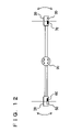
- FIG. 12 represents a position detecting system in accordance with a fifth embodiment of the present invention.
- FIGS. 13A and 13B represent a position detecting system in accordance with a sixth embodiment of the present invention.
- FIGS. 14A and 14B represent a position detecting system in accordance with a seventh embodiment of the present invention.
- FIG. 15 represents a position detecting system in accordance with an eighth embodiment of the present invention.
- FIGS. 16A , 16 B, 16 C and 16 D represent moving bodies of which positions are detected by the position detecting system in accordance with other embodiments of the present invention.
- the position detecting system in accordance with the first embodiment of the present invention includes a transmitting apparatus 20 transmitting a laser beam, and a receiving apparatus 30 provided separate from transmitting apparatus 20 .
- the position detecting system detects the position of a moving body 40 having a reflector 42 , using transmitting apparatus 20 and receiving apparatus 30 . Specifically, an azimuth ⁇ between transmitting apparatus 20 and moving body 40 (reflector 42 ), and an azimuth ⁇ between receiving apparatus 30 and moving body 40 (reflector 42 ) are detected.
- a distance L(l) between transmitting apparatus 20 and moving body 40 (reflector 42 ) and a distance L( 2 ) between receiving apparatus 30 and moving body 40 (reflector 42 ) are calculated.
- Transmitting apparatus 20 includes a shielding plate 22 , a laser transmitter 50 , and a halogen light receiver 60 .
- Laser transmitter 50 transmits a laser beam, which is a directional wave, to reflector 42 of moving body 40 .
- Halogen light receiver 60 receives reflected light of halogen, which is a non-directional wave.
- Shielding plate 22 shields direct halogen light so that halogen light receiver 60 receives only the reflected halogen light.
- Receiving apparatus 30 includes a shielding plate 32 , a laser receiver 70 , and a halogen light transmitter 80 .
- Laser receiver 70 receives the laser beam reflected from reflector 42 of moving body 40 .
- Halogen light transmitter 80 transmits non-directional halogen light.
- Shielding plate 32 shields a direct laser beam so that laser receiver 70 receives only the reflected laser beam.
- the non-directional halogen light is transmitted from halogen light transmitter 80 .
- the reflected light thereof is detected by halogen light receiver 60 .
- an azimuth ⁇ (X) at which the halogen light is received is detected.
- laser transmitter 50 transmits a laser beam at an angle that is the same as azimuth ⁇ (X).
- an azimuth ⁇ (Y) of transmitting a laser beam is detected.
- the reflected laser beam is detected by laser receiver 70 .
- an azimuth ⁇ of receiving the laser beam is detected.
- azimuth ⁇ (X) between transmitting apparatus 20 and moving body 40 can be detected, even when the position of moving body 40 is uncertain.
- the detected azimuth ⁇ (X) involves an error inherently generated as the halogen light proceeds through a space, as the azimuth is detected by receiving a reflected light. Therefore, as the secondary detection, a laser beam is transmitted, and an azimuth ⁇ (Y) of laser transmission and an azimuth ⁇ of laser reception are detected.
- the azimuth ⁇ is detected by receiving the reflected beam, and therefore, it involves an error generated when the laser beam that has been propagated through a space is received.
- the azimuth ⁇ (Y) is detected not by receiving the laser, and hence, it is free of any error generated when the laser beam that has been propagated through a space is received.
- the azimuth ⁇ (Y) is used for detecting the position of moving body 40 .
- a laser beam is used as a directional wave, while halogen light is used as non-directional wave.
- other waves such as an acoustic wave, ultrasonic wave and electromagnetic wave may be used.
- a general fluorescent lamp or an electric lamp may be used for generating non-directional wave.
- Transmitting apparatus 20 includes a control portion 24 , a memory 26 , a power supply portion 28 , and a transmitting and receiving portion 29 .
- Control portion 24 is connected to laser transmitter 50 and halogen light receiver 60 and controls operations thereof
- Memory 26 stores a program to be executed by transmitting apparatus 20 , distance D between transmitting apparatus 20 and receiving apparatus 30 , and so on.
- Transmitting and receiving portion 29 transmits and receives information related to the result of detection and result of calculation with respect to moving body 40 , to and from receiving apparatus 30 .
- Receiving apparatus 30 includes a control portion 34 , a memory 36 , a power supply portion 38 and a transmitting and receiving portion 39 .
- Control portion 34 is connected to laser receiver 70 and halogen light transmitter 80 and controls operations thereof.
- Memory 36 stores a program to be executed by receiving apparatus 30 , distance D between transmitting apparatus 20 and receiving apparatus 30 , and so on.
- Transmitting and receiving portion 39 transmits and receives information related to the result of detection and result of calculation with respect to moving body 40 , to and from transmitting apparatus 20 .
- the transmitting apparatus 20 includes a laser transmitting portion 52 for transmitting a laser beam.
- the halogen light receiver includes four halogen light receiving portions 62 A, 62 B, 62 C and 62 D that receive the halogen light.
- the halogen light receiving portions are arranged in an array (lattice) surrounding laser transmitting portion 52 such that an average azimuth of azimuths at which reflected halogen light is received by the respective halogen light receiving portions match the azimuth ⁇ between laser transmitting portion 52 (transmitting apparatus 20 ) and moving body 40 (see FIG. 1 ).
- Arrangement of respective halogen light receiving portions may be in point-symmetry or line-symmetry with laser transmitting portion 52 being the center.
- the receiving apparatus 30 includes four laser beam receiving portions 72 A, 72 B, 72 C and 72 D receiving the reflected laser beam.
- the halogen light transmitter includes a halogen light transmitting portion 82 transmitting the halogen light.
- the laser beam receiving portions are arranged in an array (lattice) surrounding halogen light transmitting portion 82 such that an average azimuth of azimuths at which reflected laser beam is received by the respective laser receiving portions match the azimuth ⁇ between halogen light transmitting portion 82 (receiving apparatus 30 ) and moving body 40 (see FIG. 1 ).
- Arrangement of respective laser receiving portions may be in point-symmetry or line-symmetry with halogen light transmitting portion 82 being the center.
- the azimuth as an average of azimuths at which the reflected halogen light is received by respective halogen light receiving portions is used as the azimuth ⁇ (X) to be detected by the primary detection described above. Further, the azimuth as an average of azimuths at which the reflected laser beam is received by respective laser receiving portions is used as the azimuth ⁇ to be detected by the secondary detection described above.
- the halogen light transmitted from halogen light transmitting portion 82 in the primary detection is reflected by reflector 42 , and enters laser transmitting portion 52 and respective halogen light receiving portions.
- azimuth ⁇ (X) at which the reflected halogen light is incident on laser transmitting portion 52 can be detected as an average of azimuths at which reflected halogen light is received by the respective halogen light receiving portions.
- the laser beam is transmitted with the same azimuth as ⁇ (X)
- the laser beam proceeds along the same optical path as the halogen light, reflected by reflector 42 and the reflected laser beam enters halogen light transmitting portion 82 and the respective laser receiving portions.
- azimuth ⁇ at which the reflected laser beam is incident on halogen light transmitting portion 82 can be detected as an average of azimuths at which reflected laser beam is received by respective laser receiving portions.
- laser transmitter 52 and laser receiving portion 72 A will be described in detail.
- the laser receiving portions other than laser receiving portion 72 A and the halogen light receiving portions all have the same structure as laser receiving portion 72 A, and therefore, detailed description thereof will not be repeated.
- laser transmitting portion 52 is supported rotatable about a rotation axis 53 .
- Laser transmitter 52 is rotated by a motor 54 to transmit the laser beam in a desired direction.
- the angle of laser transmitter 50 is detected by an angle sensor 56 .
- the angle detected by sensor 56 will be the azimuth ⁇ (Y) between transmitting apparatus 20 and moving body 40 .
- laser receiving portion 72 A is supported rotatable about a rotation axis 73 .
- Laser receiving portion 72 A is rotated by motor 74 to receive the laser beam reflected by reflector 42 .
- the angle of laser receiver 72 is detected by an angle sensor 76 .
- An average angle of angles detected by angle sensors for the respective laser receiving portions will be the azimuth ⁇ between receiving apparatus 30 and moving body 40 .
- the average angle of angles detected by the respective halogen light receiving portions will be the azimuth ⁇ (X) between transmitting apparatus 20 and moving body 40 .
- FIG. 5A is a side view of moving body 40 viewed from one side.
- FIG. 5B is a plan view of moving body 40 viewed from above.
- Moving body 40 includes five reflectors reflecting the laser beam and the halogen light. The reflectors are provided on front and rear surfaces, on opposing side surfaces and on an upper surface of moving body 40 . Each reflector is formed of a part of a spherical surface, and has a prescribed radius of curvature.
- Moving body 40 has wheels 44 at is lower surface. Moving body 40 moves to an arbitrary location by the wheels 44 .
- step 100 transmitting apparatus 20 determines whether the reflected halogen light is being received or not. If the reflected halogen light is being received, the process proceeds to S 102 . Otherwise, the process returns to S 100 , and S 100 is repeated until reflected halogen light is received.
- transmitting apparatus 20 detects azimuth ⁇ (X) at which the reflected halogen light is received.
- transmitting apparatus 20 emits a laser beam at the same angle as the azimuth ⁇ (X) at which the reflected halogen light is received.
- transmitting apparatus 20 detects the azimuth ⁇ (Y) at which the laser beam is emitted.
- transmitting apparatus 20 determines whether receiving apparatus 30 has received information related to azimuth ⁇ at which the reflected laser beam is received. If the information related to azimuth ⁇ has been received, the process proceeds to S 110 . Otherwise, the process is returned to S 108 , and S 108 is repeated until the information related to azimuth ⁇ is received.
- transmitting apparatus 20 transmits information related to azimuth ⁇ (Y) at which the laser beam is transmitted, to receiving apparatus 30 .
- transmitting apparatus 20 calculates the distance L( 1 ) between transmitting apparatus 20 and moving body 40 , from azimuth ⁇ (Y), azimuth ⁇ and the distance D between transmitting apparatus 20 and receiving apparatus 30 .
- receiving apparatus 30 determines whether the reflected laser beam is being received. If the reflected laser beam is being received, the process proceeds to S 208 . Otherwise, the process proceeds to S 202 .
- receiving apparatus 30 emits the halogen light.
- receiving apparatus 30 determines whether the reflected laser beam is being received. If the reflected laser beam is being received, the process proceeds to S 206 . Otherwise, the process is returned to S 204 , and S 204 is repeated until the reflected laser beam is received.
- receiving apparatus 30 stops emission of the halogen light.
- receiving apparatus 30 detects azimuth ⁇ at which the reflected laser beam is received.
- receiving apparatus 30 transmits information related to azimuth ⁇ to transmitting apparatus 20 .
- receiving apparatus 30 determines whether information related to azimuth ⁇ (Y) at which the laser beam is emitted from transmitting apparatus 20 has been received or not. If the information related to azimuth ⁇ (Y) has been received, the process proceeds to S 214 . Otherwise, the process is returned to S 212 , and S 212 is repeated until information related to azimuth ⁇ (Y) is received.
- receiving apparatus 30 calculates the distance L( 2 ) between receiving apparatus 30 and moving body 40 , from azimuth ⁇ (Y), azimuth ⁇ and the distance D between transmitting apparatus 20 and receiving apparatus 30 .
- receiving apparatus 30 is not receiving any reflected laser beam and the position of moving body 40 is not known at present. As the reflected laser beam is not received (NO in S 200 ), receiving apparatus 30 emits halogen light for primary detection (S 202 ).
- transmitting apparatus 20 detects the azimuth ⁇ (X) at which the reflected halogen light is received (S 102 ), transmits a laser beam at the same angle as the azimuth ⁇ (X) (S 104 ), and detects the azimuth ⁇ (Y) at which the laser beam is transmitted (S 106 ).
- receiving apparatus 30 stops emission of the halogen light (S 206 ), detects the azimuth ⁇ at which the reflected laser beam is received (S 208 ), and transmits information related to azimuth ⁇ to transmitting apparatus 30 (S 210 ).
- transmitting apparatus 20 transmits information related to azimuth ⁇ (Y) to receiving apparatus 30 ( 5110 ). Further, transmitting apparatus 20 calculates the distance L( 1 ) between transmitting apparatus 20 and moving body 40 , from the azimuth ⁇ (Y), azimuth ⁇ and the distance D between transmitting apparatus 20 and receiving apparatus 30 (S 112 ).
- receiving apparatus 30 calculates the distance L( 2 ) between transmitting apparatus 30 and moving body 40 , from the azimuth ⁇ (Y), azimuth ⁇ and the distance D between transmitting apparatus 20 and receiving apparatus 30 .
- non-directional halogen light is transmitted and the reflection thereof is received to detect the azimuth between the transmitting apparatus and the receiving apparatus, as the primary detection.
- a laser beam is transmitted at the same angle as the azimuth detected in the primary detection, the azimuth between the transmitting apparatus and the moving body is detected from the angle of laser transmission, and the azimuth between the receiving apparatus and the moving body is detected from the angle of laser reception.
- the azimuth between the transmitting apparatus and the moving body can be detected by the primary detection.
- the secondary detection the azimuth between the transmitting apparatus and the moving body, and the azimuth between the receiving apparatus and the moving body can be detected, and respective distances can be calculated.
- the azimuth between the transmitting apparatus and the moving body is detected from the angle of laser emission. Therefore, the azimuth between the transmitting apparatus and the moving body detected by the secondary detection is free of any error generated when the laser beam that has propagated through a space is received.
- the position of the moving body can be detected with high accuracy.
- the position detecting system in accordance with the second embodiment of the present invention has, in addition to the function of the position detecting system in accordance with the first embodiment, the function of changing the direction of laser emission along with the movement of moving body 40 and of tracking and detecting the position of moving body 40 .
- Other hardware configuration and process flow are the same as those of the position detecting system in accordance with the first embodiment described above. Therefore, detailed description thereof will not be repeated here.
- FIGS. 7 and 8 the method of tracking moving body 40 will be described. Assume that moving body 40 moves and reflector 42 moves by ⁇ (X) in the direction of the arrow, as shown in FIG. 7 . As a result of this movement, the position at which the reflected laser beam is incident on laser receiver 70 moves from R( 1 ) to R( 2 ), by ⁇ (Y). When we represent the amount of change in the incident angle of the laser beam to reflector 42 as ⁇ , the angle at which the reflected laser beam proceeds to laser receiver 70 changes by 2 ⁇ (the amount of change of azimuth ⁇ becomes 2 ⁇ ). As to the detection of distance ⁇ (Y), a plurality of laser receiving portions may be arranged in an array (lattice) as shown in FIG.
- a laser receiving portion to which the reflected laser beam enters among the laser receiving portions may be detected, and the distance ⁇ (Y) may be detected from the distance between the laser receiving portion that has received the laser beam before movement and the laser receiving portion that receives the laser beam after movement.
- change in the amount of light received by the plurality of receiving portions may be compared to find the amount of movement.
- Other common techniques may be used. Therefore, detailed description thereof will not be given here.
- FIG. 8 is an enlarged view of a surface of reflector 42 .
- the laser beam transmitted from laser transmitter 50 before movement is incident on the surface Q( 1 ) of reflector 42 from the direction P, at an incident angle of ⁇ (X), and is reflected in a direction R( 1 ) where laser receiver 70 exists.
- reflector 42 moves by ⁇ (X)
- the laser beam transmitted from laser transmitter 50 is incident on the surface Q( 2 ) of reflector 42 from the direction P, at an incident angle of ⁇ (Y), and is reflected in a direction R( 2 ).
- receiving apparatus 30 detects ⁇ (Y), and from the detected ⁇ (Y), ⁇ is calculated.
- the information of the calculated ⁇ is transmitted to transmitting apparatus 20 , and transmitting apparatus 20 corrects the angle of laser emission by ⁇ .
- ⁇ (Y) is ⁇ (X) multiplied by L/r, and generally L>>r. Therefore, it is possible to perceive the amount of movement ⁇ (Y) of the reflected beam using larger amount of movement, than directly measuring the amount of movement of moving body 40 . This means that even a slight movement of moving body 40 can be recognized, and therefore, tracking of the moving body with higher accuracy is possible.
- the ratio (L/r) of enlargement of ⁇ (Y) with respect to ⁇ (X) may be set arbitrarily by setting the radius of curvature r of the reflector.
- the reflector by forming the reflector to have a partial spherical surface or a partial cylindrical shape, it becomes possible to have an arbitrary radius of curvature without changing the dimension of the reflector such as the diameter or entire length, and hence, the ratio of enlargement (L/r) can be set arbitrarily.
- transmitting apparatus 20 determines whether the distance L( 1 ) between transmitting apparatus 20 and moving body 40 has been calculated or not. If the distance L( 1 ) has been calculated, the process proceeds to S 302 . Otherwise, the process is terminated.
- transmitting apparatus 20 determines whether information related to ⁇ has been received from receiving apparatus 30 or not. If the information related to ⁇ has been received, the process proceeds to S 304 . Otherwise, the process is returned to S 302 , and S 302 is repeated until the information related to ⁇ is received.
- transmitting apparatus 20 corrects the direction of laser emission by ⁇ .
- transmitting apparatus 20 detects the azimuth ⁇ (Y) of laser emission.
- transmitting apparatus 20 determines whether the information related to azimuth ⁇ of receiving the reflected laser beam has been received from receiving apparatus 30 or not. If the information related to azimuth ⁇ has been received, the process proceeds to S 310 . Otherwise, the process returns to S 308 , and S 308 is repeated until the information related to azimuth ⁇ is received.
- transmitting apparatus 20 transmits the azimuth ⁇ (Y) of laser emission to receiving apparatus 30 .
- transmitting apparatus 20 calculates the distance L( 1 ) between transmitting apparatus 20 and moving body 40 , from the azimuth ⁇ (Y), azimuth ⁇ and the distance between transmitting apparatus 20 and receiving apparatus 30 .
- receiving apparatus 30 determines whether the distance L( 2 ) between receiving apparatus 30 and moving body 40 has been calculated or not. If the distance L( 2 ) has been calculated, the process proceeds to S 402 . Otherwise, the process is terminated.
- receiving-apparatus 30 determines whether the amount of movement ⁇ (Y) of the reflected laser beam has been detected or not. If the amount ⁇ (Y) has been detected, the process proceeds to S 404 . Otherwise, the process returns to S 402 , and S 402 is repeated until the value ⁇ (Y) is detected.
- receiving apparatus 30 calculates ⁇ .
- receiving apparatus 30 transmits information related to ⁇ to transmitting apparatus 20 .
- receiving apparatus 30 detects the azimuth ⁇ at which the reflected laser beam is received.
- receiving apparatus 30 transmits the azimuth ⁇ of the reflected laser beam to transmitting apparatus 20 .
- receiving apparatus 30 determines whether the azimuth ⁇ (Y) at which the laser is transmitted has been received from transmitting apparatus 20 or not. If the azimuth ⁇ (Y) has been received, the process proceeds to S 414 . Otherwise, the process returns to S 412 , and S 412 is repeated until the azimuth ⁇ (Y) is received.
- receiving apparatus 30 calculates the distance L( 2 ) between receiving apparatus 30 and moving body 40 , from the azimuth ⁇ (Y), azimuth ⁇ and the distance D between transmitting apparatus 20 and receiving apparatus 30 .
- receiving apparatus 30 determines whether the amount of movement ⁇ (Y) of reflected laser beam has been detected or not (S 402 ). When the amount of movement ⁇ (Y) is detected (YES in S 402 ), it calculates ⁇ (S 404 ), and transmits information related to ⁇ to transmitting apparatus 20 (S 406 ).
- transmitting apparatus 20 corrects the direction of laser emission by ⁇ (S 304 ), and detects the azimuth ⁇ (Y) at which the laser is transmitted (S 306 ).
- Receiving apparatus 30 detects the azimuth ⁇ at which the reflected laser beam is received (S 408 ), and transmits information related to the azimuth ⁇ of reflected laser beam to transmitting apparatus 20 (S 410 ).
- transmitting apparatus 20 transmits information related to the azimuth ⁇ (Y) at which the laser is transmitted to receiving apparatus 30 (S 310 ).
- Transmitting apparatus 20 calculates the distance L( 1 ) between transmitting apparatus 20 and moving body 40 , from the azimuth ⁇ (Y), azimuth ⁇ and the distance D between the transmitting apparatus 20 and receiving apparatus 30 (S 312 ).
- receiving apparatus 30 calculates the distance L( 2 ) between receiving apparatus 30 and moving body 40 , from the azimuth ⁇ (Y), azimuth ⁇ and the distance D between transmitting apparatus 20 and receiving apparatus 30 (S 414 ).
- the direction of laser transmission is changed as the moving body moves. Therefore, even when the position of the moving body changes, it is possible to track the moving body and to detect its position, by changing the direction of transmitting the wave.
- transmitting apparatus 20 and receiving apparatus 30 include polarization filters 24 and 34 , respectively, in place of the shielding plate.
- Other hardware configuration and process flow are the same as those of the position detecting system in accordance with the first or second embodiment described above. Therefore, detailed description thereof will not be repeated here.
- Reflected light has higher ratio of polarized light that is vertical to the reflecting surface. Therefore, a direct laser beam and a reflected laser beam have different angles of linear polarization. Direct halogen light generally has no polarization, while reflected light is transmitted with polarization. Therefore, when the laser beam or halogen light is received through polarization filters 24 and 34 , it becomes possible to determine whether the received light is direct light or reflected light.
- transmitting apparatus 20 in accordance with the position detecting system in accordance with the fourth embodiment of the present invention includes a first laser transmitter 50 A and a second laser transmitter 50 B.
- Transmitting apparatus 30 includes a first laser receiver 70 A and a second laser receiver 70 B.
- Moving body 40 is provided with first and second reflectors 42 F and 42 G.
- the first laser transmitter 50 A transmits a laser beam to the first reflector 42 F, and the reflected beam therefrom is received by the first laser receiver 70 A.
- the second laser transmitter 50 B transmits a laser beam to the second reflector 42 G, and the reflected beam therefrom is received by the second laser receiver 70 B.
- Transmitting apparatus 20 and receiving apparatus 30 detect positions of the reflectors in the similar manner as in the first or second embodiment.
- laser beams are transmitted separately to respective ones of a plurality of reflectors, and the reflected beams from respective reflectors are received separately. Therefore, even when the moving body does not move but rotates at the same position, the rotation of the moving body can be detected, as the positions of respective reflectors change.
- the position detecting system in accordance with the fifth embodiment of the present invention includes a rotating apparatus 90 rotatably provided and coupling transmitting apparatus 20 with receiving apparatus 30 .
- Other hardware configuration and process flow are the same as those of the position detecting system in accordance with the first or second embodiment described above. Therefore, detailed description thereof will not be repeated here.
- rotating apparatus 90 can change the position and orientation of transmitting apparatus 20 and receiving apparatus 30 . Therefore, even when the moving body moves significantly or when the moving body, the transmitting apparatus and the receiving apparatus happen to be aligned on one line, it is possible to detect the position of the moving body by changing the position and orientation of the transmitting apparatus and the receiving apparatus.
- transmitting apparatus 20 is mounted on a first moving apparatus 100 .
- receiving apparatus 30 is mounted on a second moving apparatus 110 .
- transmitting apparatus 20 includes a GPS (Global Positioning System) apparatus 26 .
- Receiving apparatus 30 includes a GPS apparatus 36 .
- Transmitting apparatus 20 detects, by GPS apparatus 26 , the position of itself, and transmits information related to the position of itself to receiving apparatus 30 .
- receiving apparatus 30 detects, by GPS apparatus 36 , the position of itself, and transmits information related to the position of itself to transmitting apparatus 20 .
- transmitting apparatus 20 calculates the distance between transmitting apparatus 20 and receiving apparatus 30 from the positions of the transmitting apparatus 20 and receiving apparatus 30 .
- receiving apparatus 30 calculates the distance between receiving apparatus 30 and transmitting apparatus 20 from the positions of receiving apparatus 30 and transmitting apparatus 20 .
- the first moving apparatus 100 can move to an arbitrary position by wheels 102 .
- the second moving apparatus 110 can move to an arbitrary position by wheels 112 .
- the transmitting apparatus and the receiving apparatus are mounted on the first and second moving apparatuses, respectively. Therefore, it is possible to track and detect the position of the moving body, no matter how the moving body moves.
- transmitting apparatus 20 and receiving apparatus 30 are mounted on a first flapping robot 120 and a second flapping robot 130 , respectively.
- the first flapping robot 120 includes wing portions 122 and actuators 124 .
- the first flapping robot 120 can move in a space three-dimensionally, as wing portions 122 are moved up and down by actuators 124 .
- the second flapping robot 130 includes wing portions 132 and actuators 134 .
- the second flapping robot 130 can move in a space three-dimensionally, as wing portions 132 are moved up and down by actuators 134 .
- transmitting apparatus 20 and receiving apparatus 30 are mounted on the first and second flapping robots 120 and 130 , respectively. Therefore, three dimensional movement and tracking is possible no matter to what position the moving body moves.
- transmitting apparatus 20 does not have any halogen light receiver, and a laser beam from laser transmitter 50 sweeps from S( 1 ) to S( 2 ).
- Receiving apparatus 30 does not have a halogen light transmitter.
- Other hardware configuration is the same as that of the first or second embodiment described above.
- the process flow is the same as that of the first or second embodiment, except for the flow related to the transmission and reception of halogen light. Therefore, detailed description thereof will not be repeated here.
- the laser beam from the transmitting apparatus sweeps a predetermined scope. Therefore, a moving body of which position is uncertain can be searched.
- FIGS. 16A , 16 B, 16 C and 16 D other embodiments will be described.
- the shape of the reflectors provided on moving body 40 is different from that of the reflectors provided on moving body 40 in accordance with any of the first to seventh embodiments described above.
- Other hardware configuration and process flow are the same as those of the position detecting system in accordance with the first to seventh embodiments described above. Therefore, detailed description thereof will not be repeated here.
- the moving body of which position is detected by the position detecting system in accordance with the present embodiment includes a spherical reflector 45 A to 45 E. Therefore, the laser beam or halogen light can be reflected the same way no matter from which direction it comes, unless shielded by the moving body itself.
- the moving body 40 of which position is detected by the position detecting system in accordance with the present embodiment includes a reflector 46 A having a cylindrical surface and reflectors 46 B to 46 E having partial cylindrical convex surfaces. This allows simplification of the reflector structure, for such an application in that the moving body moves on a plane only.
- the reflector may be formed by using a partial cylindrical convex surface.
- the moving body 40 of which position is detected by the position detecting system in accordance with the present embodiment includes a reflector 47 having a convex parabolic surface.
- a position of a portion of which relative position to the reflector has been known, such as the central position of the moving body can be detected.
- the reflector may be formed by using a part of a convex or concave parabolic surface.
- the moving body 40 of which position is detected by the position detecting system in accordance with the present embodiment includes a reflector 48 A having a shape of an elliptical cylinder and reflectors 48 B to 48 E having a convex surface of partial elliptical cylinder.
- a position of a portion of which relative position to the reflector has been known, such as the central position of the moving body can be detected.
- the reflector may be formed by using a part of a concave surface of an elliptical cylinder.
Landscapes
- Physics & Mathematics (AREA)
- Electromagnetism (AREA)
- Engineering & Computer Science (AREA)
- Computer Networks & Wireless Communication (AREA)
- General Physics & Mathematics (AREA)
- Radar, Positioning & Navigation (AREA)
- Remote Sensing (AREA)
- Optical Radar Systems And Details Thereof (AREA)
- Radar Systems Or Details Thereof (AREA)
Abstract
Description
Claims (50)
Applications Claiming Priority (2)
| Application Number | Priority Date | Filing Date | Title |
|---|---|---|---|
| JP2003-297714 | 2003-08-21 | ||
| JP2003297714A JP3977303B2 (en) | 2003-08-21 | 2003-08-21 | Position detection system, transmitter and receiver in position detection system |
Publications (2)
| Publication Number | Publication Date |
|---|---|
| US20050043039A1 US20050043039A1 (en) | 2005-02-24 |
| US7474256B2 true US7474256B2 (en) | 2009-01-06 |
Family
ID=34191189
Family Applications (1)
| Application Number | Title | Priority Date | Filing Date |
|---|---|---|---|
| US10/918,018 Expired - Fee Related US7474256B2 (en) | 2003-08-21 | 2004-08-12 | Position detecting system, and transmitting and receiving apparatuses for the position detecting system |
Country Status (2)
| Country | Link |
|---|---|
| US (1) | US7474256B2 (en) |
| JP (1) | JP3977303B2 (en) |
Cited By (31)
| Publication number | Priority date | Publication date | Assignee | Title |
|---|---|---|---|---|
| US20090183125A1 (en) * | 2008-01-14 | 2009-07-16 | Prime Sense Ltd. | Three-dimensional user interface |
| US20110211754A1 (en) * | 2010-03-01 | 2011-09-01 | Primesense Ltd. | Tracking body parts by combined color image and depth processing |
| US20120013885A1 (en) * | 2010-07-14 | 2012-01-19 | Pixart Imaging Inc. | Distance measuring device and method for measuring distance |
| US20120097837A1 (en) * | 2010-10-22 | 2012-04-26 | New Japan Radio Co., Ltd. | Position detecting device using reflection type photosensors |
| US20120196541A1 (en) * | 2009-06-19 | 2012-08-02 | Cohda Wireless Pty. Ltd. | Environment estimation in a wireless communication system |
| US20140047381A1 (en) * | 2012-08-10 | 2014-02-13 | Microsoft Corporation | 3d data environment navigation tool |
| US8872762B2 (en) | 2010-12-08 | 2014-10-28 | Primesense Ltd. | Three dimensional user interface cursor control |
| US8881051B2 (en) | 2011-07-05 | 2014-11-04 | Primesense Ltd | Zoom-based gesture user interface |
| US20140330436A1 (en) * | 2007-04-24 | 2014-11-06 | Yale Security Inc. | Door closer assembly |
| US8933876B2 (en) | 2010-12-13 | 2015-01-13 | Apple Inc. | Three dimensional user interface session control |
| US8959013B2 (en) | 2010-09-27 | 2015-02-17 | Apple Inc. | Virtual keyboard for a non-tactile three dimensional user interface |
| US9030498B2 (en) | 2011-08-15 | 2015-05-12 | Apple Inc. | Combining explicit select gestures and timeclick in a non-tactile three dimensional user interface |
| US9035876B2 (en) | 2008-01-14 | 2015-05-19 | Apple Inc. | Three-dimensional user interface session control |
| US9122311B2 (en) | 2011-08-24 | 2015-09-01 | Apple Inc. | Visual feedback for tactile and non-tactile user interfaces |
| US9158375B2 (en) | 2010-07-20 | 2015-10-13 | Apple Inc. | Interactive reality augmentation for natural interaction |
| US9201501B2 (en) | 2010-07-20 | 2015-12-01 | Apple Inc. | Adaptive projector |
| US20150346319A1 (en) * | 2012-12-20 | 2015-12-03 | Hilti Aktiengesellschaft | Method and Device for Determining the Position Coordinates of a Target Object |
| US9218063B2 (en) | 2011-08-24 | 2015-12-22 | Apple Inc. | Sessionless pointing user interface |
| US9229534B2 (en) | 2012-02-28 | 2016-01-05 | Apple Inc. | Asymmetric mapping for tactile and non-tactile user interfaces |
| US9285874B2 (en) | 2011-02-09 | 2016-03-15 | Apple Inc. | Gaze detection in a 3D mapping environment |
| US9377863B2 (en) | 2012-03-26 | 2016-06-28 | Apple Inc. | Gaze-enhanced virtual touchscreen |
| US9377865B2 (en) | 2011-07-05 | 2016-06-28 | Apple Inc. | Zoom-based gesture user interface |
| US9459758B2 (en) | 2011-07-05 | 2016-10-04 | Apple Inc. | Gesture-based interface with enhanced features |
| US10209357B2 (en) * | 2016-04-28 | 2019-02-19 | Fluke Corporation | RF in-wall image registration using position indicating markers |
| US10254398B2 (en) | 2016-04-28 | 2019-04-09 | Fluke Corporation | Manipulation of 3-D RF imagery and on-wall marking of detected structure |
| US10302793B2 (en) | 2016-08-04 | 2019-05-28 | Fluke Corporation | Blending and display of RF in wall imagery with data from other sensors |
| US10444344B2 (en) | 2016-12-19 | 2019-10-15 | Fluke Corporation | Optical sensor-based position sensing of a radio frequency imaging device |
| US10473759B2 (en) * | 2017-03-28 | 2019-11-12 | GM Global Technology Operations LLC | Tool for automatic multiple radar calibration |
| US10564116B2 (en) | 2016-04-28 | 2020-02-18 | Fluke Corporation | Optical image capture with position registration and RF in-wall composite image |
| US10571591B2 (en) | 2016-04-28 | 2020-02-25 | Fluke Corporation | RF in-wall image registration using optically-sensed markers |
| US10585203B2 (en) | 2016-04-28 | 2020-03-10 | Fluke Corporation | RF in-wall image visualization |
Families Citing this family (4)
| Publication number | Priority date | Publication date | Assignee | Title |
|---|---|---|---|---|
| US8260316B2 (en) * | 2009-04-13 | 2012-09-04 | Colopl, Inc. | Movement distance falsification preventing system and method |
| CN104655161B (en) | 2013-11-21 | 2017-05-10 | 科沃斯机器人股份有限公司 | Distance measuring device and method of distance measuring device to find distance measuring initial point |
| KR101936152B1 (en) * | 2018-08-28 | 2019-01-08 | 한화시스템 주식회사 | Dirctional linear array sensor and signal processing method thereof |
| CN115183962B (en) * | 2022-07-11 | 2023-03-10 | 深圳大学 | Laser measurement method and system for bridge deflection |
Citations (69)
| Publication number | Priority date | Publication date | Assignee | Title |
|---|---|---|---|---|
| US1981884A (en) * | 1933-06-13 | 1934-11-27 | Albert H Taylor | System for detecting objects by radio |
| US2085798A (en) * | 1935-06-08 | 1937-07-06 | Telefunken Gmbh | Radio system for locating objects |
| US2411518A (en) * | 1942-05-27 | 1946-11-26 | Int Standard Electric Corp | Electromagnetic wave transmission system |
| US2650359A (en) * | 1950-03-20 | 1953-08-25 | William W Brockway | Radio navigation system |
| US2982859A (en) * | 1959-02-04 | 1961-05-02 | Engelhard Hanovia Inc | Light communication alinement system |
| US3067281A (en) * | 1945-10-01 | 1962-12-04 | Gen Electric | Underwater object locator and viewer |
| US3400363A (en) * | 1965-12-09 | 1968-09-03 | Pan American Petroleum Corp | Wavelet reconstruction process for sonic, seismic, and radar exploration |
| US3705261A (en) * | 1970-04-09 | 1972-12-05 | Symbionics Inc | Scanning system for yielding a three-dimensional display |
| US3846026A (en) * | 1971-11-01 | 1974-11-05 | Continental Oil Co | Rotating beam surveying method and apparatus |
| US4184767A (en) * | 1975-07-21 | 1980-01-22 | The United States Of America As Represented By The Secretary Of The Navy | Frequency agile optical radar |
| US4245220A (en) * | 1978-04-14 | 1981-01-13 | Plessey Handel Und Investments Ag | Target location systems |
| US4253166A (en) * | 1978-04-14 | 1981-02-24 | Plessey Handel Und Investments Ag | Target location systems |
| JPS5912370A (en) | 1982-07-12 | 1984-01-23 | Kubota Ltd | Detection of position of moving object |
| JPS60211308A (en) | 1984-04-06 | 1985-10-23 | Hitachi Ltd | Space coordinate orientation device for moving body |
| US4550250A (en) * | 1983-11-14 | 1985-10-29 | Hei, Inc. | Cordless digital graphics input device |
| US4560270A (en) * | 1981-08-07 | 1985-12-24 | Geotronics Ab | Device included in a distance meter system |
| US4568182A (en) * | 1981-12-22 | 1986-02-04 | Summagraphics Corporation | Optical system for determining the position of a cursor |
| US4621267A (en) * | 1984-09-28 | 1986-11-04 | The Boeing Company | Bearing intersection deghosting by altitude comparison system and methods |
| US4688933A (en) * | 1985-05-10 | 1987-08-25 | The Laitram Corporation | Electro-optical position determining system |
| US4712915A (en) * | 1984-05-21 | 1987-12-15 | Geotronics Ab | Arrangement for holding an instrument in alignment with a moving reflector |
| US4729660A (en) * | 1985-03-22 | 1988-03-08 | Toshihiro Tsumura | Position measuring apparatus of moving vehicle |
| US4820041A (en) * | 1986-11-12 | 1989-04-11 | Agtek Development Co., Inc. | Position sensing system for surveying and grading |
| US4912643A (en) * | 1986-10-30 | 1990-03-27 | Institute For Industrial Research And Standards | Position sensing apparatus |
| US5026153A (en) * | 1989-03-01 | 1991-06-25 | Mitsubishi Denki K.K. | Vehicle tracking control for continuously detecting the distance and direction to a preceding vehicle irrespective of background dark/light distribution |
| US5039217A (en) * | 1989-03-27 | 1991-08-13 | Mitsubishi Denki Kabushiki Kaisha | Optical transceiver apparatus for detecting distance between two cars |
| JPH03242518A (en) | 1990-02-20 | 1991-10-29 | Nec Corp | Observing apparatus for vibration of sinking part of outside plate of hull |
| JPH03295487A (en) | 1990-04-13 | 1991-12-26 | Mitsubishi Electric Corp | Detecting method for space floating body |
| US5164732A (en) * | 1980-02-13 | 1992-11-17 | Eid Electronic Identification Systems Ltd. | Highway vehicle identification system with high gain antenna |
| US5166668A (en) * | 1991-04-10 | 1992-11-24 | Data Stream Corporation | Wireless pen-type input device for use with a computer |
| JPH0527036A (en) | 1991-07-23 | 1993-02-05 | Fujitsu Ltd | Azimuth measuring device position determining device and position determinating method |
| US5243397A (en) * | 1992-11-25 | 1993-09-07 | Elop-Electrooptics Industries Ltd. | Distance measuring system |
| US5264855A (en) * | 1993-02-09 | 1993-11-23 | The United States Of America As Represented By The Secretary Of The Air Force | Technique for stationary radar target discrimination |
| JPH0618260A (en) | 1992-07-02 | 1994-01-25 | Omron Corp | Object observing apparatus |
| JPH0659016A (en) | 1992-08-07 | 1994-03-04 | Sanyo Electric Co Ltd | Position measuring device for moving body |
| JPH06317670A (en) | 1991-03-13 | 1994-11-15 | Matsushita Electric Ind Co Ltd | Inter-vehicle distance measuring device |
| US5457394A (en) * | 1993-04-12 | 1995-10-10 | The Regents Of The University Of California | Impulse radar studfinder |
| US5465094A (en) * | 1994-01-14 | 1995-11-07 | The Regents Of The University Of California | Two terminal micropower radar sensor |
| US5534868A (en) * | 1992-03-26 | 1996-07-09 | Susar A/S | Method and system for the detection and measurement of air phenomena and transmitter and receiver for use in the system |
| US5576627A (en) * | 1994-09-06 | 1996-11-19 | The Regents Of The University Of California | Narrow field electromagnetic sensor system and method |
| US5583638A (en) * | 1993-07-21 | 1996-12-10 | Hewlett-Packard Company | Angular michelson interferometer and optical wavemeter based on a rotating periscope |
| US5594413A (en) * | 1993-12-27 | 1997-01-14 | Hyundai Electronics Industries Co., Ltd. | Car collision prevention apparatus and method using dual processor and automatic sensor switching function |
| JPH0926474A (en) | 1995-07-13 | 1997-01-28 | Toshiba Corp | Radar system |
| US5926305A (en) * | 1992-10-27 | 1999-07-20 | Topcon Corporation | Marking apparatus having feedback-controlled rotational laser beam |
| US5974348A (en) * | 1996-12-13 | 1999-10-26 | Rocks; James K. | System and method for performing mobile robotic work operations |
| US5976038A (en) * | 1997-12-10 | 1999-11-02 | Toy Builders | Apparatus for detecting moving ball |
| JP2000131059A (en) | 1998-10-28 | 2000-05-12 | Omron Corp | Distance measurement method and device therefor, and start/stop control device of vehicle |
| US6137436A (en) * | 1997-06-12 | 2000-10-24 | Diehl Stiftung & Co. | Alarm sensor, in particular for a target tracking apparatus |
| US6177903B1 (en) * | 1999-06-14 | 2001-01-23 | Time Domain Corporation | System and method for intrusion detection using a time domain radar array |
| US20010004288A1 (en) * | 1999-12-16 | 2001-06-21 | Junichi Tsuji | Image reading device |
| US6278399B1 (en) * | 1999-02-22 | 2001-08-21 | Honda Giken Kogyo Kabushiki Kaisha | Radar apparatus and method for detecting malfunction of radar apparatus |
| US6381055B1 (en) * | 1998-04-16 | 2002-04-30 | At&T Corp. | Transceiver positioning in free-space optical networks |
| JP2002181925A (en) | 2000-12-18 | 2002-06-26 | Mitsubishi Electric Corp | Passive radar apparatus |
| US20020096637A1 (en) * | 1999-06-23 | 2002-07-25 | Toomey Patrick J. | Methods of distinguishing between water and water vapor in a structure |
| US20020097400A1 (en) * | 1996-01-02 | 2002-07-25 | Jung Wayne D. | Apparatus and method for measuring optical characteristics of an object |
| US6459492B1 (en) * | 1997-03-14 | 2002-10-01 | Agilent Technologies, Inc. | Non-contact position sensor |
| US6492937B1 (en) * | 2001-11-02 | 2002-12-10 | Itt Manufacturing Enterprises, Inc. | High precision range measurement technique |
| US20020196176A1 (en) * | 1986-06-03 | 2002-12-26 | Fullerton Larry W. | Time domain radio transmission system |
| US20030117810A1 (en) * | 2001-12-25 | 2003-06-26 | Koito Manufacturing Co., Ltd. | Reflector movable type headlamp for vehicle |
| US20030156420A1 (en) * | 2002-02-18 | 2003-08-21 | Masashi Tatsukawa | Vehicle lamp |
| US6650425B2 (en) * | 2000-03-24 | 2003-11-18 | Koito Manufacturing Co., Ltd. | Position measuring laser apparatus |
| US6653972B1 (en) * | 2002-05-09 | 2003-11-25 | Raytheon Company | All weather precision guidance of distributed projectiles |
| US6667724B2 (en) * | 2001-02-26 | 2003-12-23 | Time Domain Corporation | Impulse radar antenna array and method |
| US6693714B1 (en) * | 1999-03-29 | 2004-02-17 | Ando Electric Co., Ltd. | Position sensor for movable body and optical interferometer |
| US20040090626A1 (en) * | 2000-05-10 | 2004-05-13 | Uwe Wielsch | Ellipsometer |
| US6822604B2 (en) * | 2000-09-14 | 2004-11-23 | Time Domain Corp. | System and method for detecting an intruder using impulse radio technology |
| US6906639B2 (en) * | 1993-08-11 | 2005-06-14 | Dorothy Lemelson | Motor vehicle warning and control system and method |
| US6914554B1 (en) * | 2003-10-17 | 2005-07-05 | The United States Of America As Represented By The Secretary Of The Army | Radar beam steering with remote reflectors/refractors |
| US20060169876A1 (en) * | 2004-07-22 | 2006-08-03 | B.E.A. S.A. | Laser scanning and sensing device for detection around automatic doors |
| US7138938B1 (en) * | 2005-05-06 | 2006-11-21 | Ford Global Technologies, Llc | System and method for preemptively sensing an object and selectively operating both a collision countermeasure system and a parking assistance system aboard an automotive vehicle |
-
2003
- 2003-08-21 JP JP2003297714A patent/JP3977303B2/en not_active Expired - Fee Related
-
2004
- 2004-08-12 US US10/918,018 patent/US7474256B2/en not_active Expired - Fee Related
Patent Citations (69)
| Publication number | Priority date | Publication date | Assignee | Title |
|---|---|---|---|---|
| US1981884A (en) * | 1933-06-13 | 1934-11-27 | Albert H Taylor | System for detecting objects by radio |
| US2085798A (en) * | 1935-06-08 | 1937-07-06 | Telefunken Gmbh | Radio system for locating objects |
| US2411518A (en) * | 1942-05-27 | 1946-11-26 | Int Standard Electric Corp | Electromagnetic wave transmission system |
| US3067281A (en) * | 1945-10-01 | 1962-12-04 | Gen Electric | Underwater object locator and viewer |
| US2650359A (en) * | 1950-03-20 | 1953-08-25 | William W Brockway | Radio navigation system |
| US2982859A (en) * | 1959-02-04 | 1961-05-02 | Engelhard Hanovia Inc | Light communication alinement system |
| US3400363A (en) * | 1965-12-09 | 1968-09-03 | Pan American Petroleum Corp | Wavelet reconstruction process for sonic, seismic, and radar exploration |
| US3705261A (en) * | 1970-04-09 | 1972-12-05 | Symbionics Inc | Scanning system for yielding a three-dimensional display |
| US3846026A (en) * | 1971-11-01 | 1974-11-05 | Continental Oil Co | Rotating beam surveying method and apparatus |
| US4184767A (en) * | 1975-07-21 | 1980-01-22 | The United States Of America As Represented By The Secretary Of The Navy | Frequency agile optical radar |
| US4245220A (en) * | 1978-04-14 | 1981-01-13 | Plessey Handel Und Investments Ag | Target location systems |
| US4253166A (en) * | 1978-04-14 | 1981-02-24 | Plessey Handel Und Investments Ag | Target location systems |
| US5164732A (en) * | 1980-02-13 | 1992-11-17 | Eid Electronic Identification Systems Ltd. | Highway vehicle identification system with high gain antenna |
| US4560270A (en) * | 1981-08-07 | 1985-12-24 | Geotronics Ab | Device included in a distance meter system |
| US4568182A (en) * | 1981-12-22 | 1986-02-04 | Summagraphics Corporation | Optical system for determining the position of a cursor |
| JPS5912370A (en) | 1982-07-12 | 1984-01-23 | Kubota Ltd | Detection of position of moving object |
| US4550250A (en) * | 1983-11-14 | 1985-10-29 | Hei, Inc. | Cordless digital graphics input device |
| JPS60211308A (en) | 1984-04-06 | 1985-10-23 | Hitachi Ltd | Space coordinate orientation device for moving body |
| US4712915A (en) * | 1984-05-21 | 1987-12-15 | Geotronics Ab | Arrangement for holding an instrument in alignment with a moving reflector |
| US4621267A (en) * | 1984-09-28 | 1986-11-04 | The Boeing Company | Bearing intersection deghosting by altitude comparison system and methods |
| US4729660A (en) * | 1985-03-22 | 1988-03-08 | Toshihiro Tsumura | Position measuring apparatus of moving vehicle |
| US4688933A (en) * | 1985-05-10 | 1987-08-25 | The Laitram Corporation | Electro-optical position determining system |
| US20020196176A1 (en) * | 1986-06-03 | 2002-12-26 | Fullerton Larry W. | Time domain radio transmission system |
| US4912643A (en) * | 1986-10-30 | 1990-03-27 | Institute For Industrial Research And Standards | Position sensing apparatus |
| US4820041A (en) * | 1986-11-12 | 1989-04-11 | Agtek Development Co., Inc. | Position sensing system for surveying and grading |
| US5026153A (en) * | 1989-03-01 | 1991-06-25 | Mitsubishi Denki K.K. | Vehicle tracking control for continuously detecting the distance and direction to a preceding vehicle irrespective of background dark/light distribution |
| US5039217A (en) * | 1989-03-27 | 1991-08-13 | Mitsubishi Denki Kabushiki Kaisha | Optical transceiver apparatus for detecting distance between two cars |
| JPH03242518A (en) | 1990-02-20 | 1991-10-29 | Nec Corp | Observing apparatus for vibration of sinking part of outside plate of hull |
| JPH03295487A (en) | 1990-04-13 | 1991-12-26 | Mitsubishi Electric Corp | Detecting method for space floating body |
| JPH06317670A (en) | 1991-03-13 | 1994-11-15 | Matsushita Electric Ind Co Ltd | Inter-vehicle distance measuring device |
| US5166668A (en) * | 1991-04-10 | 1992-11-24 | Data Stream Corporation | Wireless pen-type input device for use with a computer |
| JPH0527036A (en) | 1991-07-23 | 1993-02-05 | Fujitsu Ltd | Azimuth measuring device position determining device and position determinating method |
| US5534868A (en) * | 1992-03-26 | 1996-07-09 | Susar A/S | Method and system for the detection and measurement of air phenomena and transmitter and receiver for use in the system |
| JPH0618260A (en) | 1992-07-02 | 1994-01-25 | Omron Corp | Object observing apparatus |
| JPH0659016A (en) | 1992-08-07 | 1994-03-04 | Sanyo Electric Co Ltd | Position measuring device for moving body |
| US5926305A (en) * | 1992-10-27 | 1999-07-20 | Topcon Corporation | Marking apparatus having feedback-controlled rotational laser beam |
| US5243397A (en) * | 1992-11-25 | 1993-09-07 | Elop-Electrooptics Industries Ltd. | Distance measuring system |
| US5264855A (en) * | 1993-02-09 | 1993-11-23 | The United States Of America As Represented By The Secretary Of The Air Force | Technique for stationary radar target discrimination |
| US5457394A (en) * | 1993-04-12 | 1995-10-10 | The Regents Of The University Of California | Impulse radar studfinder |
| US5583638A (en) * | 1993-07-21 | 1996-12-10 | Hewlett-Packard Company | Angular michelson interferometer and optical wavemeter based on a rotating periscope |
| US6906639B2 (en) * | 1993-08-11 | 2005-06-14 | Dorothy Lemelson | Motor vehicle warning and control system and method |
| US5594413A (en) * | 1993-12-27 | 1997-01-14 | Hyundai Electronics Industries Co., Ltd. | Car collision prevention apparatus and method using dual processor and automatic sensor switching function |
| US5465094A (en) * | 1994-01-14 | 1995-11-07 | The Regents Of The University Of California | Two terminal micropower radar sensor |
| US5576627A (en) * | 1994-09-06 | 1996-11-19 | The Regents Of The University Of California | Narrow field electromagnetic sensor system and method |
| JPH0926474A (en) | 1995-07-13 | 1997-01-28 | Toshiba Corp | Radar system |
| US20020097400A1 (en) * | 1996-01-02 | 2002-07-25 | Jung Wayne D. | Apparatus and method for measuring optical characteristics of an object |
| US5974348A (en) * | 1996-12-13 | 1999-10-26 | Rocks; James K. | System and method for performing mobile robotic work operations |
| US6459492B1 (en) * | 1997-03-14 | 2002-10-01 | Agilent Technologies, Inc. | Non-contact position sensor |
| US6137436A (en) * | 1997-06-12 | 2000-10-24 | Diehl Stiftung & Co. | Alarm sensor, in particular for a target tracking apparatus |
| US5976038A (en) * | 1997-12-10 | 1999-11-02 | Toy Builders | Apparatus for detecting moving ball |
| US6381055B1 (en) * | 1998-04-16 | 2002-04-30 | At&T Corp. | Transceiver positioning in free-space optical networks |
| JP2000131059A (en) | 1998-10-28 | 2000-05-12 | Omron Corp | Distance measurement method and device therefor, and start/stop control device of vehicle |
| US6278399B1 (en) * | 1999-02-22 | 2001-08-21 | Honda Giken Kogyo Kabushiki Kaisha | Radar apparatus and method for detecting malfunction of radar apparatus |
| US6693714B1 (en) * | 1999-03-29 | 2004-02-17 | Ando Electric Co., Ltd. | Position sensor for movable body and optical interferometer |
| US6177903B1 (en) * | 1999-06-14 | 2001-01-23 | Time Domain Corporation | System and method for intrusion detection using a time domain radar array |
| US20020096637A1 (en) * | 1999-06-23 | 2002-07-25 | Toomey Patrick J. | Methods of distinguishing between water and water vapor in a structure |
| US20010004288A1 (en) * | 1999-12-16 | 2001-06-21 | Junichi Tsuji | Image reading device |
| US6650425B2 (en) * | 2000-03-24 | 2003-11-18 | Koito Manufacturing Co., Ltd. | Position measuring laser apparatus |
| US20040090626A1 (en) * | 2000-05-10 | 2004-05-13 | Uwe Wielsch | Ellipsometer |
| US6822604B2 (en) * | 2000-09-14 | 2004-11-23 | Time Domain Corp. | System and method for detecting an intruder using impulse radio technology |
| JP2002181925A (en) | 2000-12-18 | 2002-06-26 | Mitsubishi Electric Corp | Passive radar apparatus |
| US6667724B2 (en) * | 2001-02-26 | 2003-12-23 | Time Domain Corporation | Impulse radar antenna array and method |
| US6492937B1 (en) * | 2001-11-02 | 2002-12-10 | Itt Manufacturing Enterprises, Inc. | High precision range measurement technique |
| US20030117810A1 (en) * | 2001-12-25 | 2003-06-26 | Koito Manufacturing Co., Ltd. | Reflector movable type headlamp for vehicle |
| US20030156420A1 (en) * | 2002-02-18 | 2003-08-21 | Masashi Tatsukawa | Vehicle lamp |
| US6653972B1 (en) * | 2002-05-09 | 2003-11-25 | Raytheon Company | All weather precision guidance of distributed projectiles |
| US6914554B1 (en) * | 2003-10-17 | 2005-07-05 | The United States Of America As Represented By The Secretary Of The Army | Radar beam steering with remote reflectors/refractors |
| US20060169876A1 (en) * | 2004-07-22 | 2006-08-03 | B.E.A. S.A. | Laser scanning and sensing device for detection around automatic doors |
| US7138938B1 (en) * | 2005-05-06 | 2006-11-21 | Ford Global Technologies, Llc | System and method for preemptively sensing an object and selectively operating both a collision countermeasure system and a parking assistance system aboard an automotive vehicle |
Non-Patent Citations (1)
| Title |
|---|
| Japanese Office Action and translation thereof. |
Cited By (47)
| Publication number | Priority date | Publication date | Assignee | Title |
|---|---|---|---|---|
| US20140330436A1 (en) * | 2007-04-24 | 2014-11-06 | Yale Security Inc. | Door closer assembly |
| US9399884B2 (en) * | 2007-04-24 | 2016-07-26 | Yale Security Inc. | Door closer assembly |
| US20090183125A1 (en) * | 2008-01-14 | 2009-07-16 | Prime Sense Ltd. | Three-dimensional user interface |
| US8166421B2 (en) * | 2008-01-14 | 2012-04-24 | Primesense Ltd. | Three-dimensional user interface |
| US9035876B2 (en) | 2008-01-14 | 2015-05-19 | Apple Inc. | Three-dimensional user interface session control |
| US9008584B2 (en) * | 2009-06-19 | 2015-04-14 | Cohda Wireless Pty. Ltd. | Environment estimation in a wireless communication system |
| US20120196541A1 (en) * | 2009-06-19 | 2012-08-02 | Cohda Wireless Pty. Ltd. | Environment estimation in a wireless communication system |
| US20110211754A1 (en) * | 2010-03-01 | 2011-09-01 | Primesense Ltd. | Tracking body parts by combined color image and depth processing |
| US8787663B2 (en) | 2010-03-01 | 2014-07-22 | Primesense Ltd. | Tracking body parts by combined color image and depth processing |
| US8605258B2 (en) * | 2010-07-14 | 2013-12-10 | Pixart Imaging Inc. | Distance measuring device and method for measuring distance |
| US20120013885A1 (en) * | 2010-07-14 | 2012-01-19 | Pixart Imaging Inc. | Distance measuring device and method for measuring distance |
| US9158375B2 (en) | 2010-07-20 | 2015-10-13 | Apple Inc. | Interactive reality augmentation for natural interaction |
| US9201501B2 (en) | 2010-07-20 | 2015-12-01 | Apple Inc. | Adaptive projector |
| US8959013B2 (en) | 2010-09-27 | 2015-02-17 | Apple Inc. | Virtual keyboard for a non-tactile three dimensional user interface |
| US20120097837A1 (en) * | 2010-10-22 | 2012-04-26 | New Japan Radio Co., Ltd. | Position detecting device using reflection type photosensors |
| US8907263B2 (en) * | 2010-10-22 | 2014-12-09 | New Japan Radio Co., Ltd. | Position detecting device using reflection type photosensors |
| TWI461649B (en) * | 2010-10-22 | 2014-11-21 | New Japan Radio Co Ltd | Position detecting device using reflection type photosensors |
| US8872762B2 (en) | 2010-12-08 | 2014-10-28 | Primesense Ltd. | Three dimensional user interface cursor control |
| US8933876B2 (en) | 2010-12-13 | 2015-01-13 | Apple Inc. | Three dimensional user interface session control |
| US9454225B2 (en) | 2011-02-09 | 2016-09-27 | Apple Inc. | Gaze-based display control |
| US9285874B2 (en) | 2011-02-09 | 2016-03-15 | Apple Inc. | Gaze detection in a 3D mapping environment |
| US9342146B2 (en) | 2011-02-09 | 2016-05-17 | Apple Inc. | Pointing-based display interaction |
| US8881051B2 (en) | 2011-07-05 | 2014-11-04 | Primesense Ltd | Zoom-based gesture user interface |
| US9459758B2 (en) | 2011-07-05 | 2016-10-04 | Apple Inc. | Gesture-based interface with enhanced features |
| US9377865B2 (en) | 2011-07-05 | 2016-06-28 | Apple Inc. | Zoom-based gesture user interface |
| US9030498B2 (en) | 2011-08-15 | 2015-05-12 | Apple Inc. | Combining explicit select gestures and timeclick in a non-tactile three dimensional user interface |
| US9122311B2 (en) | 2011-08-24 | 2015-09-01 | Apple Inc. | Visual feedback for tactile and non-tactile user interfaces |
| US9218063B2 (en) | 2011-08-24 | 2015-12-22 | Apple Inc. | Sessionless pointing user interface |
| US9229534B2 (en) | 2012-02-28 | 2016-01-05 | Apple Inc. | Asymmetric mapping for tactile and non-tactile user interfaces |
| US9377863B2 (en) | 2012-03-26 | 2016-06-28 | Apple Inc. | Gaze-enhanced virtual touchscreen |
| US11169611B2 (en) | 2012-03-26 | 2021-11-09 | Apple Inc. | Enhanced virtual touchpad |
| US9881396B2 (en) | 2012-08-10 | 2018-01-30 | Microsoft Technology Licensing, Llc | Displaying temporal information in a spreadsheet application |
| US9317963B2 (en) | 2012-08-10 | 2016-04-19 | Microsoft Technology Licensing, Llc | Generating scenes and tours in a spreadsheet application |
| US9996953B2 (en) | 2012-08-10 | 2018-06-12 | Microsoft Technology Licensing, Llc | Three-dimensional annotation facing |
| US10008015B2 (en) | 2012-08-10 | 2018-06-26 | Microsoft Technology Licensing, Llc | Generating scenes and tours in a spreadsheet application |
| US20140047381A1 (en) * | 2012-08-10 | 2014-02-13 | Microsoft Corporation | 3d data environment navigation tool |
| US20150346319A1 (en) * | 2012-12-20 | 2015-12-03 | Hilti Aktiengesellschaft | Method and Device for Determining the Position Coordinates of a Target Object |
| US10564116B2 (en) | 2016-04-28 | 2020-02-18 | Fluke Corporation | Optical image capture with position registration and RF in-wall composite image |
| US10254398B2 (en) | 2016-04-28 | 2019-04-09 | Fluke Corporation | Manipulation of 3-D RF imagery and on-wall marking of detected structure |
| US10571591B2 (en) | 2016-04-28 | 2020-02-25 | Fluke Corporation | RF in-wall image registration using optically-sensed markers |
| US10585203B2 (en) | 2016-04-28 | 2020-03-10 | Fluke Corporation | RF in-wall image visualization |
| US10830884B2 (en) | 2016-04-28 | 2020-11-10 | Fluke Corporation | Manipulation of 3-D RF imagery and on-wall marking of detected structure |
| US10209357B2 (en) * | 2016-04-28 | 2019-02-19 | Fluke Corporation | RF in-wall image registration using position indicating markers |
| US11635509B2 (en) | 2016-04-28 | 2023-04-25 | Fluke Corporation | Manipulation of 3-D RF imagery and on-wall marking of detected structure |
| US10302793B2 (en) | 2016-08-04 | 2019-05-28 | Fluke Corporation | Blending and display of RF in wall imagery with data from other sensors |
| US10444344B2 (en) | 2016-12-19 | 2019-10-15 | Fluke Corporation | Optical sensor-based position sensing of a radio frequency imaging device |
| US10473759B2 (en) * | 2017-03-28 | 2019-11-12 | GM Global Technology Operations LLC | Tool for automatic multiple radar calibration |
Also Published As
| Publication number | Publication date |
|---|---|
| JP2005069772A (en) | 2005-03-17 |
| US20050043039A1 (en) | 2005-02-24 |
| JP3977303B2 (en) | 2007-09-19 |
Similar Documents
| Publication | Publication Date | Title |
|---|---|---|
| US7474256B2 (en) | Position detecting system, and transmitting and receiving apparatuses for the position detecting system | |
| US7876457B2 (en) | Laser metrology system and method | |
| JP6781265B2 (en) | Radar installation judgment using unstructured data | |
| JP4350385B2 (en) | Method for automatically searching for target marks, device for automatically searching for target marks, receiving unit, geodometer and geodetic system | |
| US10698094B2 (en) | 3D-position determination method and device | |
| EP1334465B1 (en) | Remote attitude and position indicating system | |
| US20150346319A1 (en) | Method and Device for Determining the Position Coordinates of a Target Object | |
| JP7120723B2 (en) | laser scanner system | |
| JPH05240940A (en) | Optical measuring system | |
| JP4862300B2 (en) | Laser distance measuring device | |
| JPH11271448A (en) | Calibration device for laser range finder and laser distance measuring apparatus equipped with it | |
| JP3690260B2 (en) | Vehicle distance measurement method | |
| JP2007248058A (en) | Optical axis adjustment method of radar device | |
| JP2015031648A (en) | Laser tracker | |
| JP2000329848A (en) | Probing method and device thereof | |
| JPH11183174A (en) | Position measuring apparatus for mobile | |
| JP2008122127A (en) | Target position locating apparatus | |
| JP2001074458A (en) | Position detecting facility for moving object | |
| JPH02102481A (en) | Ultrasonic guidance device | |
| JPS5870181A (en) | Radar system | |
| JP7082853B2 (en) | Rangefinder, distance measurement method, thickness gauge device and thickness measurement method | |
| EP4253994A1 (en) | Sensor calibration based on strings of detections | |
| JP7050342B2 (en) | Calibration method of optical comb coordinate measuring device, automatic tracking device, automatic tracking optical comb positioning device, and optical comb coordinate measuring device | |
| WO2023013171A1 (en) | Distance estimation device, antena device, power feeding system, power feeding apparatus, and power feeding method | |
| JP2000081487A (en) | Surveying method and device |
Legal Events
| Date | Code | Title | Description |
|---|---|---|---|
| AS | Assignment |
Owner name: SHARP KABUSHIKI KAISHA, JAPAN Free format text: ASSIGNMENT OF ASSIGNORS INTEREST;ASSIGNORS:OHTA, YOSHIJI;HARA, KEITA;HAMAMOTO, MASAKI;REEL/FRAME:015690/0635 Effective date: 20040721 |
|
| STCF | Information on status: patent grant |
Free format text: PATENTED CASE |
|
| FEPP | Fee payment procedure |
Free format text: PAYOR NUMBER ASSIGNED (ORIGINAL EVENT CODE: ASPN); ENTITY STATUS OF PATENT OWNER: LARGE ENTITY |
|
| FPAY | Fee payment |
Year of fee payment: 4 |
|
| FEPP | Fee payment procedure |
Free format text: PAYER NUMBER DE-ASSIGNED (ORIGINAL EVENT CODE: RMPN); ENTITY STATUS OF PATENT OWNER: LARGE ENTITY Free format text: PAYOR NUMBER ASSIGNED (ORIGINAL EVENT CODE: ASPN); ENTITY STATUS OF PATENT OWNER: LARGE ENTITY |
|
| FPAY | Fee payment |
Year of fee payment: 8 |
|
| FEPP | Fee payment procedure |
Free format text: MAINTENANCE FEE REMINDER MAILED (ORIGINAL EVENT CODE: REM.); ENTITY STATUS OF PATENT OWNER: LARGE ENTITY |
|
| LAPS | Lapse for failure to pay maintenance fees |
Free format text: PATENT EXPIRED FOR FAILURE TO PAY MAINTENANCE FEES (ORIGINAL EVENT CODE: EXP.); ENTITY STATUS OF PATENT OWNER: LARGE ENTITY |
|
| STCH | Information on status: patent discontinuation |
Free format text: PATENT EXPIRED DUE TO NONPAYMENT OF MAINTENANCE FEES UNDER 37 CFR 1.362 |
|
| FP | Lapsed due to failure to pay maintenance fee |
Effective date: 20210106 |