WO2024190338A1 - 密封装置 - Google Patents
密封装置 Download PDFInfo
- Publication number
- WO2024190338A1 WO2024190338A1 PCT/JP2024/006313 JP2024006313W WO2024190338A1 WO 2024190338 A1 WO2024190338 A1 WO 2024190338A1 JP 2024006313 W JP2024006313 W JP 2024006313W WO 2024190338 A1 WO2024190338 A1 WO 2024190338A1
- Authority
- WO
- WIPO (PCT)
- Prior art keywords
- lip
- sealing device
- seal body
- conductive
- inward
- Prior art date
- Legal status (The legal status is an assumption and is not a legal conclusion. Google has not performed a legal analysis and makes no representation as to the accuracy of the status listed.)
- Ceased
Links
Images


Classifications
-
- F—MECHANICAL ENGINEERING; LIGHTING; HEATING; WEAPONS; BLASTING
- F16—ENGINEERING ELEMENTS AND UNITS; GENERAL MEASURES FOR PRODUCING AND MAINTAINING EFFECTIVE FUNCTIONING OF MACHINES OR INSTALLATIONS; THERMAL INSULATION IN GENERAL
- F16J—PISTONS; CYLINDERS; SEALINGS
- F16J15/00—Sealings
- F16J15/16—Sealings between relatively-moving surfaces
- F16J15/32—Sealings between relatively-moving surfaces with elastic sealings, e.g. O-rings
- F16J15/3204—Sealings between relatively-moving surfaces with elastic sealings, e.g. O-rings with at least one lip
- F16J15/3216—Sealings between relatively-moving surfaces with elastic sealings, e.g. O-rings with at least one lip supported in a direction parallel to the surfaces
-
- F—MECHANICAL ENGINEERING; LIGHTING; HEATING; WEAPONS; BLASTING
- F16—ENGINEERING ELEMENTS AND UNITS; GENERAL MEASURES FOR PRODUCING AND MAINTAINING EFFECTIVE FUNCTIONING OF MACHINES OR INSTALLATIONS; THERMAL INSULATION IN GENERAL
- F16J—PISTONS; CYLINDERS; SEALINGS
- F16J15/00—Sealings
- F16J15/16—Sealings between relatively-moving surfaces
- F16J15/32—Sealings between relatively-moving surfaces with elastic sealings, e.g. O-rings
- F16J15/3248—Sealings between relatively-moving surfaces with elastic sealings, e.g. O-rings provided with casings or supports
- F16J15/3252—Sealings between relatively-moving surfaces with elastic sealings, e.g. O-rings provided with casings or supports with rigid casings or supports
-
- F—MECHANICAL ENGINEERING; LIGHTING; HEATING; WEAPONS; BLASTING
- F16—ENGINEERING ELEMENTS AND UNITS; GENERAL MEASURES FOR PRODUCING AND MAINTAINING EFFECTIVE FUNCTIONING OF MACHINES OR INSTALLATIONS; THERMAL INSULATION IN GENERAL
- F16J—PISTONS; CYLINDERS; SEALINGS
- F16J15/00—Sealings
- F16J15/16—Sealings between relatively-moving surfaces
- F16J15/32—Sealings between relatively-moving surfaces with elastic sealings, e.g. O-rings
- F16J15/3268—Mounting of sealing rings
- F16J15/3276—Mounting of sealing rings with additional static sealing between the sealing, or its casing or support, and the surface on which it is mounted
-
- F—MECHANICAL ENGINEERING; LIGHTING; HEATING; WEAPONS; BLASTING
- F16—ENGINEERING ELEMENTS AND UNITS; GENERAL MEASURES FOR PRODUCING AND MAINTAINING EFFECTIVE FUNCTIONING OF MACHINES OR INSTALLATIONS; THERMAL INSULATION IN GENERAL
- F16J—PISTONS; CYLINDERS; SEALINGS
- F16J15/00—Sealings
- F16J15/16—Sealings between relatively-moving surfaces
- F16J15/32—Sealings between relatively-moving surfaces with elastic sealings, e.g. O-rings
- F16J15/3284—Sealings between relatively-moving surfaces with elastic sealings, e.g. O-rings characterised by their structure; Selection of materials
Definitions
- the present invention relates to a sealing device.
- a sealing device is known that is disposed in the gap between the outer peripheral surface of a rotating shaft and the inner peripheral surface of a shaft hole in a housing having a shaft hole into which the rotating shaft is inserted.
- the sealing device can be incorporated into a reduction gear 1900 of an electric vehicle (EV) or a fuel cell vehicle (FCV), for example.
- the reducer 1900 includes a housing 1300, a first rotating shaft 1201, a second rotating shaft 1202, and a third rotating shaft 1203 provided in the housing 1300, and a plurality of bearings 1400 provided in the housing 1300 and supporting the first rotating shaft 1201, the second rotating shaft 1202, and the third rotating shaft 1203, respectively.
- Electric power from the battery 1500 is supplied to the electric motor 1700 via the inverter 1600, and the electric motor 1700 is driven to rotate the first rotating shaft 1201, which is the output shaft of the electric motor 1700.
- the first rotating shaft 1201, the second rotating shaft 1202, and the third rotating shaft 1203 are connected in this order via a gear 1220.
- the rotation of the first rotating shaft 1201 is transmitted from the first rotating shaft 1201 to the second rotating shaft 1202, and is further transmitted from the second rotating shaft 1202 to the third rotating shaft 1203.
- the rotation of the first rotating shaft 1201 is transmitted to the third rotating shaft 1203 at a desired reduction ratio.
- the third rotating shaft 1203 is provided with a wheel 1800 .
- induced currents generated in the electric motor 1700 can cause AM radio electromagnetic noise from the rotating shafts, or sparks can occur at the bearings 1400, causing electrolytic corrosion in the bearings 1400.
- One existing technology for this purpose is earth brushes, but these have problems such as the need to secure a dedicated space and the generation of brush wear powder.
- the sealing device of Patent Document 1 (the seal ring of the same document) comprises a seal body having a lip portion (the seal lip of the same document), and a conductive lip (the front seal of the same document) provided on the atmospheric side surface of the seal body.
- Patent Document 1 leaves room for improvement in terms of the integrity of the conductive lip and the seal body.
- the present invention was made in consideration of the above problems, and provides a sealing device with a structure that can achieve good integration between the conductive lip and the seal body.
- a sealing device that is disposed in a gap between an outer circumferential surface of a rotating shaft and an inner circumferential surface of a shaft hole in a housing having a shaft hole into which the rotating shaft is inserted, and seals the gap, comprising:
- the seal body comprises a core metal made of a metal material and a seal body component made of an elastic body and integrated with the core metal.
- the seal body component comprises a seal body including a lip portion, a conductive lip and a conductive guard ring attached to the seal body; Equipped with the protective ring has a contact portion that contacts the housing and an inward extending portion that extends radially inward from the contact portion, The conductive lip is sandwiched between the inward extension and the seal body, thereby providing a sealing device that is integrated with the seal body.
- the present invention makes it possible to achieve good integration between the conductive lip and the seal body.
- FIG. 1 is a diagram showing a sealing device according to a first embodiment, illustrating a cross-sectional end surface along the axis of a rotating shaft.
- FIG. 2 is a partially enlarged view of FIG. 1 is a diagram showing a sealing device according to a first modified example of the first embodiment, showing a cross-sectional end surface along the axis of a rotating shaft.
- FIG. 13 is a diagram showing a sealing device according to a second modified example of the first embodiment, showing a cross-sectional end surface along the axis of a rotating shaft.
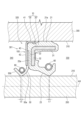
- FIG. 13 is a diagram showing a sealing device according to a third modified example of the first embodiment, showing a cross-sectional end surface along the axis of a rotating shaft.
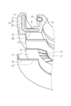
- FIG. 11 is an exploded perspective view of a sealing device according to a third modified example of the first embodiment.
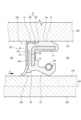
- 13 is a diagram showing a sealing device according to a fourth modified example of the first embodiment, showing a cross-sectional end surface along the axis of a rotating shaft.
- FIG. 13 is a diagram showing a sealing device according to a fifth modified example of the first embodiment, showing a cross-sectional end surface along the axis of a rotating shaft.
- FIG. 13 is a diagram showing a sealing device according to a second embodiment, showing a cross-sectional end surface along the axis of a rotating shaft.
- FIG. 1 is a schematic diagram for explaining a problem with a general sealing device.
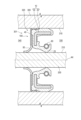
- the sealing device 100 of this embodiment is disposed in a gap 320 between an outer peripheral surface 210 of a rotating shaft 200 and an inner peripheral surface 310 of an axial hole 301 in a housing 300 having an axial hole 301 into which the rotating shaft 200 is inserted, and seals the gap 320.
- the sealing device 100 includes a seal body 10 , and a conductive lip 50 and a conductive protective ring 40 attached to the seal body 10 .
- the seal body 10 is configured to include a core 30 made of a metallic material, and a seal body constituent member 20 made of an elastic body and integrated with the core 30.
- the seal body constituent member 20 includes a lip portion 23.
- the protective ring 40 has a contact portion 41 that contacts the housing 300 and an inward extending portion 42 that extends radially inward from the contact portion 41 .
- the conductive lip 50 is integrated with the seal body 10 by being sandwiched between the inward extension portion 42 and the seal body 10 .
- the sealing device 100 is disposed in the gap 320 so that the central axis AX of the sealing device 100 coincides with the axis of the rotating shaft 200 .
- a direction perpendicular to the central axis AX will be referred to as a radial direction.
- a direction going away from the central axis AX is referred to as the radially outer direction, and a direction going toward the central axis AX is referred to as the radially inner direction.
- the direction going around the central axis AX is referred to as the circumferential direction.
- the direction along the central axis AX may simply be referred to as the axial direction.
- one side (the right side in Figs. 1 and 2) in the direction along the central axis AX is the inner side (inside the machine) of the mechanism in which the sealing device 100 is provided, and this direction is referred to as the inner side 330.
- the other side (the left side in Figs. 1 and 2) in the direction along the central axis AX is the outer side (atmosphere side) of the mechanism in which the sealing device 100 is provided, and this direction is referred to as the outer side 340.
- the sealing device 100 of this embodiment when the sealing device 100 is assembled to the housing 300 and the gap 320 of the axial hole 301 of the housing 300 is sealed, the protective ring 40 and the conductive lip 50 each form a part of a conductive path between the housing 300 and the rotating shaft 200. This ensures electrical continuity between the rotating shaft 200 and the housing 300 through the protective ring 40 and the conductive lip 50, that is, the rotating shaft can be earthed to the housing 300. This makes it possible to suppress the generation of electromagnetic noise from AM radio from the rotating shaft and the occurrence of electrolytic corrosion in the bearings.
- the conductive lip 50 is integrated with the seal body 10 by being clamped between the inward extension portion 42 and the seal body 10, thereby achieving good integration between the conductive lip 50 and the seal body 10. Since the sealing device 100 can be replaced with an existing sealing device, a space dedicated to an earth brush is not required, and the generation of brush wear powder can be prevented. Furthermore, unlike the technology that ensures electrical conductivity between the rotating shaft 200 and the housing 300 using the conductive lip alone, this is ensured by the conductive lip 50 and the protective ring 40, which is a metal component, so that the electrical resistance of the conductive path from the rotating shaft 200 to the housing 300 can also be reduced.
- the lip portion 23 may be an oil lip or a dust lip.
- the lip portion 23 is an oil lip. That is, the seal body 10 constitutes an oil seal body.
- the sealing device 100 combines a seal body 10 having a lip portion 23 which is an oil lip, and a conductive lip 50, thereby achieving both oil sealing performance and conductivity while reducing the number of parts and installation space. By locating the conductive lip 50 on the outer side 340 (atmosphere side) of the contact point between the lip portion 23, which is the oil lip, and the rotating shaft 200, conductivity can be imparted without impairing the oil seal performance.
- the sealing device 100 prevents foreign matter from entering from the outer side 340 to the inner side 330 by the lip portion 23 and the conductive lip 50, and prevents leakage of lubricant from the inner side 330 to the outer side 340 by the lip portion 23.
- An example of a mechanism in which the sealing device 100 is disposed (attached) is a reduction gear for an electric vehicle (EV) or a fuel cell vehicle (FCV), and includes a housing 300 made of a metal material.
- the housing 300 has a shaft hole 301 into which the rotating shaft 200 is inserted.
- the sealing device 100 and the rotating shaft 200 the sealing device 100 is inserted and fixed into the shaft hole 301 first, and then the rotating shaft 200 is inserted.
- the seal body constituent member 20 is formed in an annular shape centered on the central axis AX.
- the seal body constituent member 20 has, for example, a body abutting portion 21 formed in a cylindrical shape concentric with the central axis AX, a body inward extending portion 22 extending radially inward like an inner flange from one end (end on the outer side 340) of the body abutting portion 21 in the axial direction, and a lip portion 23 extending in the axial direction (toward the inner side 330) from the radially inner end of the body inward extending portion 22.
- the lip portion 23 also has a shape that can be said to be cylindrical and concentric with the central axis AX.
- the lip portion 23 is disposed inside the main body abutment portion 21 and spaced apart from the main body abutment portion 21, and the main body abutment portion 21 and the lip portion 23 face each other in the radial direction.
- the seal body constituent member 20 is formed in a three-dimensional shape that corresponds to the movement trajectory of the cut end surface shape of the seal body constituent member 20 shown in Figure 2 when the cut end surface shape is rotated once around the central axis AX.
- a portion of the outer circumferential surface of the main body abutment portion 21 serves as a contact surface 21 a that is pressed circumferentially against the inner circumferential surface 310 of the shaft hole 301 .
- the lip portion 23 is pressed circumferentially against an outer circumferential surface 210 of the rotating shaft 200, and slides against the outer circumferential surface 210 when the rotating shaft 200 rotates. Sealing performance is ensured by the pressure contact points between the contact surface 21 a and the inner circumferential surface 310 and the pressure contact points between the lip portion 23 and the outer circumferential surface 210 .
- the pressure contact area between the contact surface 21a and the inner peripheral surface 310 and the pressure contact area between the lip portion 23 and the outer peripheral surface 210 will be collectively referred to as a sealed area.
- the lip portion 23 is an oil lip, and a region on the inner side 330 of the sealed portion is filled with a lubricant such as lubricating oil.
- the material of the seal body component 20 can be a general sealing rubber material.
- elastic materials include synthetic rubbers such as nitrile rubber (NBR), hydrogenated nitrile rubber (H-NBR), acrylic rubber (ACM), and fluororubber (FKM).
- the seal body component 20 is formed as a single unit. More specifically, the seal body component 20 is integrally formed with the core metal 30 .
- the core bar 30 (and, if necessary, the garter spring 60 described below) can be placed in a molding die not shown, uncrosslinked rubber material can be injected, and then the rubber material can be crosslinked by heating and pressurizing the cavity of the molding die, thereby obtaining a seal body 10 in which the seal body constituent member 20 and the core bar 30 are molded as a single unit.
- Examples of the metal material constituting the core bar 30 include stainless steel (SUS) and cold rolled steel (SPCC).
- the core bar 30 can be formed by pressing or forging.
- the core wire 30 has, for example, a tubular portion 31 formed in a cylindrical shape concentric with the central axis AX, and a core wire inward extension portion 32 extending radially inward in the form of an inner flange from one end (the end on the outer side 340) of the tubular portion 31 in the axial direction.
- the core metal inward extending portion 32 is formed in a flat plate shape perpendicular to the central axis AX and in a doughnut shape.
- the core bar 30 is formed into a three-dimensional shape that corresponds to the movement locus of the cut end surface shape of the core bar 30 shown in FIG. 2 when the cut end surface shape is rotated once around the central axis AX.
- the core metal 30 is entirely embedded in the seal body constituent member 20 and is not exposed from the seal body constituent member 20 .
- the tubular portion 31 is disposed, for example, from the inside of the main body abutment portion 21 to the inside of the boundary between the main body abutment portion 21 and the main body inward extending portion 22.
- the core metal inward extending portion 32 is disposed from the inside of the boundary between the main body abutment portion 21 and the main body inward extending portion 22 to the inside of the main body inward extending portion 22.
- the inner peripheral edge of the core metal inward extending portion 32 is located in the vicinity of the boundary between the main body inward extending portion 22 and the lip portion 23.
- the material of the protective ring 40 is preferably a metallic material, for example, stainless steel (SUS) or cold rolled steel (SPCC).
- the protection ring 40 can be formed by pressing or forging.
- the conductive lip 50 is formed in a donut shape centered on the central axis AX.
- a portion (a radially outer portion) of the conductive lip 50 is disposed along a surface facing the outer side 340 in the main body inward extending portion 22 of the seal body constituent member 20 .
- the radially inner portion of the conductive lip 50 extends radially inward further than the inward extension portion 42.
- the radially inner portion of the conductive lip 50 protrudes radially inward from the radially inner end portion of the main body inward extension portion 22.
- the portion of the conductive lip 50 that extends radially inward beyond the inward extension 42 is bent toward the outer side 340 (the left side in FIG. 2 ).
- the conductive lip 50 is formed in a three-dimensional shape that corresponds to the movement trajectory of the cut end surface shape of the conductive lip 50 shown in FIG. 2 when the cut end surface shape is rotated once around the central axis AX.
- the tip portion (the radially inner end portion) of the conductive lip 50 contacts the outer peripheral surface 210 of the rotating shaft 200 in a circumferential manner, thereby ensuring electrical conductivity between the rotating shaft 200 and the conductive lip 50.
- the tip of the conductive lip 50 slides against the outer circumferential surface 210 when the rotating shaft 200 rotates.
- the conductive lip 50 is not required to have sealing properties.
- the material of the conductive lip 50 can be a material that is specialized for conductivity, such as conductive rubber or conductive resin.
- a preferred example of the material of the conductive lip 50 is conductive PTFE (fluororesin: PolyTetraFluoroEthylene).
- the garter spring 60 is made of a coil spring, both ends of which are connected to each other, and the axial center of the coil spring is looped in an annular shape.
- the axial center of the coil spring goes around the central axis AX once.
- the garter spring 60 is formed in an annular shape along the circumferential direction.
- the garter spring 60 is a tension-type coil spring that exerts a biasing force in a direction that shortens its axial length. Because the garter spring 60 has an annular loop shape, the garter spring 60 exerts a biasing force in a direction that shortens the radius of the loop.
- the portion of the lip portion 23 that is pressed against the outer peripheral surface 210 is a portion that is separated (toward the inner side 330) from the boundary between the main body inward extension portion 22 and the lip portion 23.
- the portion of the lip portion 23 that is closer to the main body inward extension portion 22 than the portion that is pressed against the outer peripheral surface 210, and the boundary between the lip portion 23 and the main body inward extension portion 22 are not in contact with the outer peripheral surface 210, and a gap is created between these portions and the outer peripheral surface 210.
- the seal body component 20 and the inwardly extending portion 42 of the protective ring 40 sandwich the conductive lip 50 . More specifically, of the core metal 30 and the seal body constituent member 20, only the seal body constituent member 20 clamps the conductive lip 50 (the radially outer portion of the conductive lip 50) together with the inward extension portion 42, and the core metal 30 does not clamp the conductive lip 50.
- the inward extension portion 42 is disposed along the surface of the outer side 340 (the left side in FIG. 2 ) of the main body inward extension portion 22 , and the conductive lip 50 is sandwiched between the main body inward extension portion 22 and the inward extension portion 42 .
- the seal body component 20 has a recess 22a in which a portion of the conductive lip 50 (the radially outer portion of the conductive lip 50) is disposed. Therefore, during and after assembly of the sealing device 100, the conductive lip 50 can be more stably positioned and fixed to the seal body component 20, and ultimately to the seal body 10. In other words, the sealing device 100 is easy to manufacture and has excellent structural stability.
- the recess 22a is formed on the surface of the outer side 340 (the left side in FIG. 2 ) of the main body inward extension portion 22.
- the depth of the recess 22a (the dimension in the direction along the central axis AX) is less than the thickness dimension of the conductive lip 50 before being assembled to the seal body 10, and the conductive lip 50 is sandwiched in a compressed state between the inward extension portion 42 and the bottom surface of the recess 22a.
- the outer periphery of the conductive lip 50 is positioned by the outer periphery of the recess 22a. Thus, the conductive lip 50 fits against the seal body component 20 .
- the distance from the inner peripheral edge to the outer peripheral edge of the conductive lip 50 i.e., ⁇ (outer diameter of the conductive lip 50)-(inner diameter of the conductive lip 50) ⁇ /2, is shorter than the distance from the outer peripheral surface 210 of the rotating shaft 200 to the inner peripheral surface 310 of the housing 300, i.e., ⁇ (inner diameter of the shaft hole 301)-(outer diameter of the rotating shaft 200) ⁇ /2.
- the outer peripheral edge of the conductive lip 50 is located radially inward from the contact surface 21a of the seal body constituent member 20.
- the outer peripheral edge of the conductive lip 50 is located radially inward from the inner peripheral surface (of the abutment portion 41) of the protective ring 40. For this reason, a structure in which the conductive lip 50 is fitted into the recess 22a can be easily realized. Because the conductive lip 50 is formed to such dimensions, the outer peripheral edge of the conductive lip 50 does not reach the inner peripheral surface 310 (is spaced apart from the inner peripheral surface 310) (unlike the conductive lip of Patent Document 1 (the front seal in the same document)).
- the protective ring 40 is fixed to the seal body component 20 . More specifically, the abutment portion 41 of the protective ring 40 is fixed by crimping to the outer circumferential surface of the end portion of the outer side 340 of the seal body constituent member 20 . In the axial direction, the range in which the abutment portion 41 is located roughly overlaps with the range in which the main body inward extension portion 22 of the seal main body component 20 is located, and the abutment portion 41 is crimped and fixed to the outer peripheral surface of the boundary between the main body abutment portion 21 and the main body inward extension portion 22.
- the sealing device 100 is configured as described above.
- the assembly work of the conductive lip 50 and the protective ring 40 to the seal body 10 can be performed, for example, by first aligning the conductive lip 50 with respect to the seal body 10, and then fitting the protective ring 40 to the seal body 10. That is, after placing a portion (the radially outer portion) of the conductive lip 50 in the recess 22a of the main body inward extension portion 22, the abutment portion 41 of the protective ring 40 is fitted externally to the seal body constituent member 20, whereby the conductive lip 50 and the protective ring 40 can be assembled to the seal body 10.
- the conductive lip 50 may be flat as a whole, or the conductive lip 50 may be bent as shown in Figure 2 from the state before the conductive lip 50 is assembled to the seal body 10.
- the conductive lip 50 is flat (donut-shaped) before being assembled to the seal body 10
- the conductive lip 50 is assembled to the seal body 10, and the radially outer portion of the conductive lip 50 is sandwiched and compressed between the inward extension portion 42 and the main body inward extension portion 22, causing distortion in the conductive lip 50.
- the portion of the conductive lip 50 that extends radially inward beyond the inward extension portion 42 is bent toward the inward extension portion 42 side (left side in FIG. 2). This is because the inner peripheral end of the inward extension portion 42 is located radially outward from the inner peripheral end of the portion of the main body inward extension portion 22 that is disposed along the conductive lip 50.
- the sealing device 100 is fixed to the housing 300. That is, the sealing device 100 is inserted into the axial hole 301 so that the contact surface 21a and the abutment portion 41 are pressed against and fixed to the inner circumferential surface 310, thereby fixing the sealing device 100 to the housing 300.
- the inner diameter of the conductive lip 50 is smaller than the inner diameter of the lip portion 23 .
- the contact area between the rotating shaft 200 and the conductive lip 50 is larger than the contact area between the rotating shaft 200 and the lip portion 23 after the rotating shaft 200 is inserted into the sealing device 100. That is, it is possible to realize a structure in which the distance L2 is longer than the distance L1 shown in Fig. 2. This makes it possible to more reliably ensure electrical continuity by the conductive lip 50.
- the lip portion 23 has higher rigidity than the conductive lip 50, and even if the contact area between the rotating shaft 200 and the lip portion 23 is smaller than the contact area between the rotating shaft 200 and the conductive lip 50, the sealing performance of the lip portion 23 can be sufficiently ensured.
- the sealing device 100 of this modified example differs from the sealing device 100 of the first embodiment described above in the points described below, but in other respects is configured in the same manner as the sealing device 100 of the first embodiment described above.
- the radially inner end (edge) of the inward extending portion 42 of the protective ring 40 is bent toward the conductive lip 50 to form a bent portion 42 b.
- the bent portion 42b presses the conductive lip 50, so that the tip of the conductive lip 50 can always maintain a state of contact with the outer circumferential surface 210 of the rotating shaft 200. Therefore, it is possible to suppress a decrease in the adhesion of the conductive lip 50 to the rotating shaft 200 caused by aging deterioration of the conductive lip 50, and electrical conduction between the rotating shaft 200 and the housing 300 can be maintained.
- the bent portion 42b is bent toward one side (the inner side 330: the right side in FIG. 3 ) based on the portion other than the bent portion 42b of the inward extending portion 42.
- the bent portion 42b is bent in the direction opposite to the bending direction of the conductive lip 50 (the left side in FIG. 3 ), and presses the conductive lip 50 in that direction. This enables the bent portion 42b to press the conductive lip 50 against the rotating shaft 200, and prevents the conductive lip 50 from deforming in a direction away from the rotating shaft 200 (radially outward) even if the conductive lip 50 deteriorates over time.
- the sealing device 100 of this modified example differs from the sealing device 100 of the first embodiment described above in the points described below, but in other respects is configured in the same manner as the sealing device 100 of the first embodiment described above.
- the core metal 30 and the inwardly extending portion 42 of the protective ring 40 sandwich the conductive lip 50 . Since the core metal 30 is a metal member having higher rigidity than the seal body constituent member 20 , the conductive lip 50 can be more stably sandwiched between the inward extension portion 42 and the seal body 10 .
- the radially outer portion of the conductive lip 50 is clamped between the inward extension portion 42 and the core wire 30, and the radially outer portion of the conductive lip 50, particularly the radially inner portion, is clamped between the inward extension portion 42 and the seal body component member 20.
- the present invention is not limited to this example, and in the seal body 10, the portion that sandwiches the radially outer portion of the conductive lip 50 together with the inward extending portion 42 may be only the core metal 30.
- the core metal inward extending portion 32 is formed, for example, in a flat plate shape perpendicular to the central axis AX, except for a radially inner end (edge) (bent portion 32b described below), and the radially inner end forms a bent portion 32b bent in a crank shape toward the inner side 330 (the right side in FIG. 4 ).
- a portion formed in a flat plate shape perpendicular to the central axis AX and a boundary portion between the core metal inward extending portion 32 and the tubular portion 31 are exposed on the outer surface (the surface of the outer side 340) of the seal body 10.
- a portion of the surface facing the outer side 340 serves as a contact surface 32 a that comes into surface contact with the conductive lip 50 .
- the protective ring 40 is fixed to the core metal 30.
- the protective ring 40 is fixed to the core metal 30, which is a metal member, the retention of the protective ring 40 relative to the seal body 10 can be improved.
- a portion of the outer surface of the portion from the tubular portion 31 of the core wire 30 to the boundary between the tubular portion 31 and the core wire inward extension portion 32 is exposed to the outer surface of the seal body 10, and this exposed portion has a contact surface 31a that is in face contact with the inner surface of the abutment portion 41 of the protective ring 40.
- the abutment portion 41 is directly crimped and fixed to the contact surface 31 a. More specifically, the contact surface 31 a is exposed in a portion including an end portion of the outer circumferential surface of the seal body 10 on the outer side 340 .
- the conductive path from the rotating shaft 200 to the housing 300 includes a path that passes through the conductive lip 50, the core metal 30, and the protective ring 40, in addition to the path that passes through the conductive lip 50 and the protective ring 40. This also makes it possible to reduce the electrical resistance of the conductive path from the rotating shaft 200 to the housing 300.
- the seal body component 20 does not have a recess 22a.
- the sealing device 100 of this modified example differs from the sealing device 100 of the first embodiment described above in the points described below, but in other respects is configured in the same manner as the sealing device 100 of the first embodiment described above.
- the sealing device 100 further includes a disc spring 70 interposed between the inward extension portion 42 of the protective ring 40 and the conductive lip 50, and the disc spring 70 presses the portion of the conductive lip 50 that extends radially inward more than the inward extension portion 42 toward the side opposite the inward extension portion 42 (i.e., the inner side 330).
- This allows the tip of the conductive lip 50 to maintain contact with the outer circumferential surface 210 of the rotating shaft 200.
- This makes it possible to prevent the adhesion of the conductive lip 50 to the rotating shaft 200 from decreasing due to deterioration of the conductive lip 50 over time, and allows electrical conduction between the rotating shaft 200 and the housing 300 to be maintained.
- the shape of the disc spring 70 is not particularly limited, but as an example, the disc spring 70 has a flat, donut-shaped main body 71 perpendicular to the central axis AX, and a plurality of blades 72 protruding radially inward from the inner peripheral edge of the main body 71.
- the blades 72 are arranged side by side (e.g., at equal intervals) along the circumferential direction of the main body 71.
- a plurality of slits 73 extending radially are formed in the blades 72.
- the blades 72 are bent toward the outer side 340 with the main body 71 as a reference.
- the disc spring 70 may have an inner peripheral portion (not shown) formed in a shape corresponding to the outer peripheral surface of a truncated cone (frustum cone) centered on the central axis AX.
- the disc spring 70 is preferably made of a metallic material.
- the entire conductive lip 50 is flat as shown in FIG. 6, and the conductive lip 50 is sandwiched and compressed between the inward extension portion 42, the disc spring 70, and the main body inward extension portion 22, causing the conductive lip 50 to bend as shown in FIG. 5.
- the present invention is not limited to this example, and the conductive lip 50 may be bent as shown in FIG. 5 before the conductive lip 50 is sandwiched and compressed between the inward extension portion 42, the disc spring 70, and the main body inward extension portion 22.
- the sealing device 100 of this modified example differs from the sealing device 100 of the first embodiment described above in the points described below, but in other respects is configured in the same manner as the sealing device 100 of the first embodiment described above.
- the portion of the conductive lip 50 that extends radially inward beyond the inward extension 42 has a base 50a extending radially inward from the inward extension 42, and a tip 50b that is folded back radially outward from a radially inner end of the base 50a.
- the sealing device 100 further includes a garter spring 80 that is disposed at the boundary between the base 50a and the tip 50b and that restrains the portion of the conductive lip 50 that extends radially inward beyond the inward extension 42 against the rotating shaft 200.
- the garter spring 80 is similar to the garter spring 60 and is formed in an annular loop shape along the circumferential direction.
- the garter spring 80 is disposed in a circumferential manner on a surface facing radially outward at the boundary between the base portion 50a and the tip portion 50b of the conductive lip 50. As a result, the garter spring 80 presses the conductive lip 50 radially inward. Therefore, according to this modification, the adhesion of the conductive lip 50 to the rotating shaft 200 can be improved.
- the portion of the conductive lip 50 that comes into circumferential contact and slides against the outer circumferential surface 210 of the rotating shaft 200 is the portion facing radially inward at the boundary between the base portion 50a and the tip portion 50b.
- the portion of the conductive lip 50 that extends radially inward beyond the inward extension 42 is preferably formed to be thicker than the radially outer portion of the conductive lip 50, and by doing so, excessive deformation of the conductive lip 50 due to the biasing force of the garter spring 80 can be suppressed.
- the sealing device 100 of this modified example differs from the sealing device 100 of the first embodiment described above in the points described below, but in other respects is configured in the same manner as the sealing device 100 of the first embodiment described above.
- a portion disposed along the conductive lip 50 has a backup portion 22b that locally protrudes radially inward.
- the portion of the seal body 10 that is disposed along the conductive lip 50 (and the backup portion 22 b ) is a part of the seal body constituent member 20 .
- the sealing device 100 of this embodiment differs from the sealing device 100 of the first embodiment described above in the points described below, but in other respects is configured in the same manner as the sealing device 100 of the first embodiment described above.
- the lip portion 23 of the seal body 10 is a dust lip.
- the sealing device 100 combines a seal body 10 having a lip portion 23 which is a dust lip, and a conductive lip 50, thereby achieving both dust sealing performance and conductivity while reducing the number of parts and installation space.
- the conductive lip 50 By disposing the conductive lip 50 on the inner side 330 of the contact point between the lip portion 23, which is the dust lip, and the rotating shaft 200, it is possible to impart conductivity without impairing the dust seal performance. In particular, even in water-soaked environments where it was difficult to use earth brushes, electrical conductivity can be ensured with a small number of parts.
- the sealing device 100 prevents foreign matter from entering from the outer side 340 to the inner side 330 by means of the lip portion 23 and the conductive lip 50 .
- a separate oil seal (having an oil lip) may be disposed on the inner side 330 of the conductive lip 50 .
- the portion of the seal body component 20 arranged along the inner surface 310 was described as including the main body abutment portion 21 and the boundary portion between the main body abutment portion 21 and the main body inward extension portion 22.
- the entire portion of the seal body constituent member 20 that is disposed along the inner circumferential surface 310 is the body abutment portion 21 . Therefore, in this embodiment, the main body contact portion 21 of the seal main body constituent member 20 is common to the first embodiment in that it has a shape that can be described as cylindrical.
- a portion of the main body abutment portion 21 (a portion on the inner side 330) extends like an eave from the radially outer end of the main body inward extension portion 22 toward the inner side 330 (the right side in FIG. 9).
- the lip portion 23 extends obliquely from the radially inner end of the main body inward extension portion 22 radially inward and toward the outer side 340 (the left side in FIG. 9 ).
- the seal body component 20 further includes an outward extension portion 25 extending toward the outer side 340 from a surface of the outer side 340 of the body inward extension portion 22.
- the outward extension portion 25 is disposed radially outward from the lip portion 23.
- a slinger 90 is fixed to the rotating shaft 200.
- the slinger 90 rotates in conjunction with the rotation of the rotating shaft 200.
- the slinger 90 is formed, for example, in a stepped flange shape that shifts in stages toward the inner side 330 in the radially outward direction.
- the outward extension portion 25 extends toward the inside of the gap between the slinger 90 and the outer circumferential surface 210 of the rotating shaft 200 .
- the recess 22 a is formed on the surface of the main body inward extending portion 22 facing the inner side 330 .
- the conductive lip 50 is disposed in the recess 22a in the same manner as in the first embodiment, and is assembled to the seal body constituent member 20. However, the conductive lip 50 is bent toward the inner side 330 (the right side in FIG. 9 ).
- the cylindrical portion 31 of the core metal 30 is embedded in the main body abutment portion 21. However, a portion of the cylindrical portion 31 may be exposed from the main body abutment portion 21 (from the seal main body constituent member 20).
- the core metal inward extending portion 32 is embedded from inside the boundary between the main body abutment portion 21 and the main body inward extending portion 22 to inside the main body inward extending portion 22.
- the core metal inward extending portion 32 may be formed in a flat flange shape, or may be partially bent to fit the shape of the seal main body constituent member 20.
- the contact portion 41 of the protective ring 40 is formed in a cylindrical shape with an extremely short axial dimension, and is fixed by crimping to the tip of the portion of the main body contact portion 21 that extends like an eave as described above (the tip of the inner side 330).
- the inward extending portion 42 of the protective ring 40 includes an outer flange portion 421 , an intermediate cylindrical portion 422 , and an inner flange portion 423 .
- the outer flange portion 421 extends radially inward like an inner flange from the end of the inner side 330 of the abutment portion 41.
- the outer flange portion 421 is disposed along the tip surface (the end surface of the inner side 330) of the portion of the main body abutment portion 21 extending like an eave as described above.
- the intermediate cylindrical portion 422 is formed in a cylindrical shape coaxial with the central axis AX.
- the intermediate cylindrical portion 422 extends from a radially inner end of the outer flange portion 421 toward the outer side 340.
- the intermediate cylindrical portion 422 is disposed along the inner circumferential surface of the portion of the main body abutment portion 21 that extends in an eave-like manner as described above.
- the inner flange portion 423 extends radially inwardly like an inner flange from the end portion of the intermediate cylindrical portion 422 on the outer side 340 side.
- the inner flange portion 423 is disposed along the surface of the main body inward extending portion 22 facing the inner side 330.
- the portion of the protective ring 40 that sandwiches the conductive lip 50 together with the main body inward extending portion 22 is the inner flange portion 423 .
- a sealing device that is disposed in a gap between an outer circumferential surface of a rotating shaft and an inner circumferential surface of a shaft hole in a housing having a shaft hole into which the rotating shaft is inserted, and seals the gap
- the seal body comprises a core metal made of a metal material and a seal body component made of an elastic body and integrated with the core metal.
- the seal body component comprises a seal body including a lip portion, a conductive lip and a conductive guard ring attached to the seal body; Equipped with the protective ring has a contact portion that contacts the housing and an inward extending portion that extends radially inward from the contact portion, A sealing device in which the conductive lip is integrated with the seal body by being sandwiched between the inward extension portion and the seal body.
- the seal body component has a recess in which a portion of the conductive lip is disposed.
- a sealing device according to any one of (1) to (3), wherein the core metal, together with the inwardly extending portion, sandwiches the conductive lip.
- the sealing device according to any one of (1) to (4), wherein the protective ring is fixed to the seal body constituent member.
- the sealing device according to any one of (1) to (5), wherein the protection ring is fixed to the core metal.
- the connector further includes a disc spring interposed between the inward extension and the conductive lip, A sealing device described in any one of (1) to (6), wherein the disc spring presses a portion of the conductive lip that extends radially inward from the inward extension portion toward the opposite side to the inward extension portion.
- a sealing device according to any one of (1) to (9), wherein the lip portion is an oil lip.
- a sealing device according to any one of (1) to (9), wherein the lip portion is a dust lip.
- Seal body 20 Seal body constituent member 21 Body abutment portion 21a Contact surface 22 Body inner extension portion 22a Recess 22b Backup portion 23 Lip portion 25 Outer extension portion 30 Core metal 31 Cylindrical portion 31a Contact surface 32 Core metal inward extension portion 32a Contact surface 32b Bending portion 40 Protective ring 41 Abutment portion 42 Inward extension portion 42b Bending portion 50 Conductive lip 50a Base portion 50b Tip portion 60 Garter spring 70 Disc spring 71 Body portion 72 Wing portion 73 Slit 80 Garter spring 90 Slinger 100 Sealing device 200 Rotating shaft 210 Outer peripheral surface 300 Housing 301 Shaft hole 310 Inner peripheral surface 320 Gap 330 Inner side 340 Outer side 421 Outer flange portion 422 Intermediate cylindrical portion 423 Inner flange portion 1000 Sealing device 1201 First rotating shaft 1202 Second rotating shaft 1203 Third rotating shaft 1220 Gear 1300 Housing 1400 Bearing 1500 Battery 1600 Inverter 1700 Electric motor 1800 Wheel 1900 Speed reducer
Landscapes
- Engineering & Computer Science (AREA)
- General Engineering & Computer Science (AREA)
- Mechanical Engineering (AREA)
- Sealing With Elastic Sealing Lips (AREA)
Priority Applications (4)
| Application Number | Priority Date | Filing Date | Title |
|---|---|---|---|
| EP24770451.3A EP4678952A1 (en) | 2023-03-10 | 2024-02-21 | Sealing device |
| KR1020257029446A KR20250144431A (ko) | 2023-03-10 | 2024-02-21 | 밀봉 장치 |
| CN202480015328.2A CN120813792A (zh) | 2023-03-10 | 2024-02-21 | 密封装置 |
| JP2025506641A JPWO2024190338A1 (https=) | 2023-03-10 | 2024-02-21 |
Applications Claiming Priority (2)
| Application Number | Priority Date | Filing Date | Title |
|---|---|---|---|
| JP2023037276 | 2023-03-10 | ||
| JP2023-037276 | 2023-03-10 |
Publications (1)
| Publication Number | Publication Date |
|---|---|
| WO2024190338A1 true WO2024190338A1 (ja) | 2024-09-19 |
Family
ID=92755397
Family Applications (1)
| Application Number | Title | Priority Date | Filing Date |
|---|---|---|---|
| PCT/JP2024/006313 Ceased WO2024190338A1 (ja) | 2023-03-10 | 2024-02-21 | 密封装置 |
Country Status (5)
| Country | Link |
|---|---|
| EP (1) | EP4678952A1 (https=) |
| JP (1) | JPWO2024190338A1 (https=) |
| KR (1) | KR20250144431A (https=) |
| CN (1) | CN120813792A (https=) |
| WO (1) | WO2024190338A1 (https=) |
Citations (5)
| Publication number | Priority date | Publication date | Assignee | Title |
|---|---|---|---|---|
| JP2014142065A (ja) | 2013-01-22 | 2014-08-07 | Carl Freudenberg Kg | シールリング及び該シールリングを備えるシール装置 |
| CN112984116A (zh) * | 2021-03-29 | 2021-06-18 | 烟台润蚨祥油封有限公司 | 一种油气密封件 |
| US11073210B2 (en) * | 2018-10-01 | 2021-07-27 | Carl Freudenberg Kg | Sealing element |
| CN214404686U (zh) * | 2021-02-07 | 2021-10-15 | 青岛众力诚达智能科技有限公司 | 一种反向唇口密封带压密封介质加载的密封结构 |
| JP2023037276A (ja) | 2021-09-03 | 2023-03-15 | キヤノン株式会社 | 光学系、撮像装置、車載システム、および移動装置 |
Family Cites Families (1)
| Publication number | Priority date | Publication date | Assignee | Title |
|---|---|---|---|---|
| KR101542570B1 (ko) | 2013-06-03 | 2015-08-06 | 다주건설 (주) | 수평 착정 장치 |
-
2024
- 2024-02-21 CN CN202480015328.2A patent/CN120813792A/zh active Pending
- 2024-02-21 WO PCT/JP2024/006313 patent/WO2024190338A1/ja not_active Ceased
- 2024-02-21 KR KR1020257029446A patent/KR20250144431A/ko active Pending
- 2024-02-21 JP JP2025506641A patent/JPWO2024190338A1/ja active Pending
- 2024-02-21 EP EP24770451.3A patent/EP4678952A1/en active Pending
Patent Citations (5)
| Publication number | Priority date | Publication date | Assignee | Title |
|---|---|---|---|---|
| JP2014142065A (ja) | 2013-01-22 | 2014-08-07 | Carl Freudenberg Kg | シールリング及び該シールリングを備えるシール装置 |
| US11073210B2 (en) * | 2018-10-01 | 2021-07-27 | Carl Freudenberg Kg | Sealing element |
| CN214404686U (zh) * | 2021-02-07 | 2021-10-15 | 青岛众力诚达智能科技有限公司 | 一种反向唇口密封带压密封介质加载的密封结构 |
| CN112984116A (zh) * | 2021-03-29 | 2021-06-18 | 烟台润蚨祥油封有限公司 | 一种油气密封件 |
| JP2023037276A (ja) | 2021-09-03 | 2023-03-15 | キヤノン株式会社 | 光学系、撮像装置、車載システム、および移動装置 |
Non-Patent Citations (1)
| Title |
|---|
| See also references of EP4678952A1 |
Also Published As
| Publication number | Publication date |
|---|---|
| EP4678952A1 (en) | 2026-01-14 |
| CN120813792A (zh) | 2025-10-17 |
| JPWO2024190338A1 (https=) | 2024-09-19 |
| KR20250144431A (ko) | 2025-10-10 |
Similar Documents
| Publication | Publication Date | Title |
|---|---|---|
| JP7214807B2 (ja) | 密封装置 | |
| JP7664978B2 (ja) | 導電構造、導電経路形成方法、及び、密封装置の通電方法 | |
| JP2023138842A5 (ja) | 導電構造、導電経路形成方法、及び、密封装置の通電方法 | |
| US11428322B2 (en) | Sealing apparatus | |
| US20260058529A1 (en) | Electrically conductive structure and electrically conductive sealing device | |
| JP2024175009A (ja) | 導電性密封装置 | |
| JP2018035855A (ja) | 密封装置 | |
| CN108343675A (zh) | 旋转机械的密封构造、旋转机械以及密封构件 | |
| WO2024190338A1 (ja) | 密封装置 | |
| JP7760092B2 (ja) | 密封装置 | |
| JP7752273B1 (ja) | 導電構造体及び導電方法 | |
| JP6674229B2 (ja) | 密封装置 | |
| WO2025210892A1 (ja) | 密封装置 | |
| US20260078825A1 (en) | Conductive sliding member, sealing device, and manufacturing method of sealing device | |
| JP7686894B1 (ja) | 導電構造体及び導電密封装置 | |
| JP7720738B2 (ja) | 密封装置 | |
| WO2026074896A1 (ja) | 導電性樹脂組成物、導電摺動体、及び導電構造体 | |
| WO2024262362A1 (ja) | 密封装置 | |
| JP2014109283A (ja) | 密封装置 |
Legal Events
| Date | Code | Title | Description |
|---|---|---|---|
| 121 | Ep: the epo has been informed by wipo that ep was designated in this application |
Ref document number: 24770451 Country of ref document: EP Kind code of ref document: A1 |
|
| ENP | Entry into the national phase |
Ref document number: 2025506641 Country of ref document: JP Kind code of ref document: A |
|
| WWE | Wipo information: entry into national phase |
Ref document number: 2025506641 Country of ref document: JP Ref document number: 202480015328.2 Country of ref document: CN |
|
| ENP | Entry into the national phase |
Ref document number: 1020257029446 Country of ref document: KR Free format text: ST27 STATUS EVENT CODE: A-0-1-A10-A15-NAP-PA0105 (AS PROVIDED BY THE NATIONAL OFFICE) |
|
| WWE | Wipo information: entry into national phase |
Ref document number: 2024770451 Country of ref document: EP |
|
| WWP | Wipo information: published in national office |
Ref document number: 1020257029446 Country of ref document: KR |
|
| NENP | Non-entry into the national phase |
Ref country code: DE |
|
| WWP | Wipo information: published in national office |
Ref document number: 202480015328.2 Country of ref document: CN |
|
| ENP | Entry into the national phase |
Ref document number: 2024770451 Country of ref document: EP Effective date: 20251010 |
|
| ENP | Entry into the national phase |
Ref document number: 2024770451 Country of ref document: EP Effective date: 20251010 |
|
| ENP | Entry into the national phase |
Ref document number: 2024770451 Country of ref document: EP Effective date: 20251010 |
|
| ENP | Entry into the national phase |
Ref document number: 2024770451 Country of ref document: EP Effective date: 20251010 |
|
| WWP | Wipo information: published in national office |
Ref document number: 2024770451 Country of ref document: EP |