WO2024190293A1 - コネクタ - Google Patents
コネクタ Download PDFInfo
- Publication number
- WO2024190293A1 WO2024190293A1 PCT/JP2024/005730 JP2024005730W WO2024190293A1 WO 2024190293 A1 WO2024190293 A1 WO 2024190293A1 JP 2024005730 W JP2024005730 W JP 2024005730W WO 2024190293 A1 WO2024190293 A1 WO 2024190293A1
- Authority
- WO
- WIPO (PCT)
- Prior art keywords
- housing
- outer conductor
- elastic contact
- contact portion
- connection member
- Prior art date
- Legal status (The legal status is an assumption and is not a legal conclusion. Google has not performed a legal analysis and makes no representation as to the accuracy of the status listed.)
- Ceased
Links
Images




Classifications
-
- H—ELECTRICITY
- H01—ELECTRIC ELEMENTS
- H01R—ELECTRICALLY-CONDUCTIVE CONNECTIONS; STRUCTURAL ASSOCIATIONS OF A PLURALITY OF MUTUALLY-INSULATED ELECTRICAL CONNECTING ELEMENTS; COUPLING DEVICES; CURRENT COLLECTORS
- H01R12/00—Structural associations of a plurality of mutually-insulated electrical connecting elements, specially adapted for printed circuits, e.g. printed circuit boards [PCB], flat or ribbon cables, or like generally planar structures, e.g. terminal strips, terminal blocks; Coupling devices specially adapted for printed circuits, flat or ribbon cables, or like generally planar structures; Terminals specially adapted for contact with, or insertion into, printed circuits, flat or ribbon cables, or like generally planar structures
- H01R12/70—Coupling devices
- H01R12/71—Coupling devices for rigid printing circuits or like structures
-
- H—ELECTRICITY
- H01—ELECTRIC ELEMENTS
- H01R—ELECTRICALLY-CONDUCTIVE CONNECTIONS; STRUCTURAL ASSOCIATIONS OF A PLURALITY OF MUTUALLY-INSULATED ELECTRICAL CONNECTING ELEMENTS; COUPLING DEVICES; CURRENT COLLECTORS
- H01R24/00—Two-part coupling devices, or either of their cooperating parts, characterised by their overall structure
- H01R24/38—Two-part coupling devices, or either of their cooperating parts, characterised by their overall structure having concentrically or coaxially arranged contacts
- H01R24/40—Two-part coupling devices, or either of their cooperating parts, characterised by their overall structure having concentrically or coaxially arranged contacts specially adapted for high frequency
- H01R24/50—Two-part coupling devices, or either of their cooperating parts, characterised by their overall structure having concentrically or coaxially arranged contacts specially adapted for high frequency mounted on a PCB [Printed Circuit Board]
Definitions
- This disclosure relates to connectors.
- the connector disclosed in Patent Document 1 comprises an insulating housing, a conductive shell covering the outer surface of the housing, and a conductive ground member connected to the shell.
- the shell has a housing connection part that is connected to the housing.
- the housing connection part is formed by bending and raising the inner part of a cut made in the upper plate part of the shell.
- An opening is formed in the upper plate of the shell when the housing connection is bent up. This raises concerns that noise may enter the connector through the opening, potentially resulting in a loss of shielding performance for the connector.
- the present disclosure therefore aims to provide a connector that can improve shielding performance.
- the connector of the present disclosure is a connector comprising an insulating housing, a conductive outer conductor held in the housing and including a portion exposed to the rear of the housing, and a plate-shaped conductive connecting member disposed between the outer surfaces of the housing and the outer conductor, the connecting member having a first elastic contact portion that contacts the outer surface of the outer conductor and an outer elastic contact portion that protrudes outward away from the outer surface of the housing.
- This disclosure makes it possible to provide a connector that can improve shielding performance.
- FIG. 1 is a perspective view of a connector according to a first embodiment of the present disclosure.
- FIG. 2 is a front view of the connector shown in FIG.
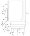
- FIG. 3 is a side view of the connector shown in FIG.
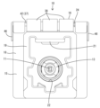
- FIG. 4 is a rear view of the connector shown in FIG.
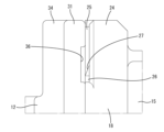
- FIG. 5 is a cross-sectional view taken along line AA of FIG. 6 is an enlarged cross-sectional side view of a portion where the second elastic contact portion contacts the opposing surface of the outer conductor in the connector shown in FIG. 1.
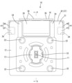
- FIG. FIG. 7 is a rear view of the housing shown in FIG. 8 is an enlarged plan view showing an insertion groove formed between the opposing surfaces of the outer conductor and the housing and its surrounding structure in the connector shown in FIG.
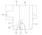
- FIG. 9 is an enlarged side view showing an insertion groove formed between the opposing surfaces of the outer conductor and the housing and its surrounding structure in the connector shown in FIG.
- FIG. 10 is a perspective view of the outer conductor shown in FIG.
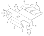
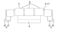
- FIG. 11 is a perspective view of the connection member shown in FIG. 12 is a front view of the connection member shown in FIG. 1.
- FIG. 10 is a perspective view of the outer conductor shown in FIG.
- the connector of the present disclosure comprises: (1) An electrical connector comprising an insulating housing, a conductive outer conductor held in the housing and including a portion exposed to the rear of the housing, and a plate-shaped conductive connecting member disposed between the outer surfaces of the housing and the outer conductor, the connecting member having a first elastic contact portion in contact with the outer surface of the outer conductor and an outer elastic contact portion protruding outward away from the outer surface of the housing.
- the outer conductor is electrically connected to the external conductor via the connection member. Since the outer conductor and the connection member are separate, there is no need to provide an opening due to the connection member in the outer conductor. In other words, the outer conductor can be electrically connected to the external conductor via the connection member without providing a contact portion on the outer conductor for electrically connecting to the external conductor by contacting the external conductor. Therefore, it is not necessary to form a housing connection portion on the outer conductor, which is formed by cutting and raising the upper plate portion of the shell as in the conventional case, and therefore an opening due to the provision of the housing connection portion is not formed in the outer conductor.
- the above configuration can further suppress the intrusion of noise into the inside of the connector by the outer conductor, thereby improving the shielding performance.
- the shape of the external elastic contact portion can be designed without being restricted by the shape of the outer conductor or the housing, so that the needs of users can be met.
- connection member is a plate-like member that is disposed between the outer surfaces of the housing and the outer conductor.
- the first elastic contact portion contacts the outer surface of the outer conductor, and the outer elastic contact portion merely protrudes outward from the outer surface of the housing. This means that the mounting structure of the connection member between the housing and the outer conductor does not become particularly complicated.
- the housing and the outer conductor each have opposing surfaces that face each other in the front-to-rear direction
- the connecting member has a second elastic contact portion that is interposed between the opposing surfaces of the housing and the outer conductor and contacts the opposing surfaces of the outer conductor in a non-removable state.
- the second elastic contact portion contacts the outer conductor separately from the first elastic contact portion. This increases the reliability of the electrical connection between the connection member and the outer conductor.
- the second elastic contact portion also has the function of preventing the connection member from slipping out from between the opposing surfaces of the outer conductor and the housing. This simplifies the structure of the connection member compared to when the connection member is provided with a contact function and a slip-out prevention function separately.
- the outer conductor has a main body and a flange protruding outward from the main body, the housing has an opposing wall facing the flange, the connection member has a base supported in a positioned state by the opposing wall, and the first elastic contact portion extends from the base and contacts the rear surface of the flange.
- the base is supported by the opposing wall, and the first elastic contact portion is in contact with the rear surface of the flange portion, so that the mounting structure for the connection member can be efficiently formed by utilizing the flange portion of the outer conductor and the opposing wall of the housing.
- the connector 10 is a shielded connector.
- the connector 10 includes a conductive inner conductor 11, a conductive outer conductor 12 surrounding the outer periphery of the inner conductor 11, an insulating dielectric 13 interposed between the inner conductor 11 and the outer conductor 12, an insulating housing 15 holding the outer conductor 12, and a conductive connecting member 16 arranged between the outer conductor 12 and the housing 15.
- the housing 15 is capable of being fitted to a mating connector (not shown).
- the front side of the front-rear direction is the side where the housing 15 is fitted to the mating connector.
- the arrow X in FIG. 1 is the front side.
- the left-right direction is based on the left-right direction in FIG. 2.
- the left-right direction is synonymous with the width direction.
- the arrow Y in FIG. 1 is the left side.
- the up-down direction is based on the up-down direction in FIG. 1.
- the up-down direction is synonymous with the height direction.
- the arrow Z in FIG. 1 is the upper side.
- the inner conductor 11 is made of metal, has a tab or pin shape, and is elongated in the front-rear direction.
- the dielectric 13 is made of synthetic resin, and has a housing chamber 17 extending in the front-rear direction.
- the inner conductor 11 is inserted into the housing chamber 17 from the rear and is housed therein and held by the dielectric 13.
- the front end of the inner conductor 11 protrudes forward of the dielectric 13 and is electrically connected to a mating inner conductor (not shown).
- the rear end of the inner conductor 11 protrudes rearward of the dielectric 13 and is inserted into a through hole 101 of the circuit board 100 and is soldered to a conductive path of the circuit board 100 for electrical connection.
- the housing 15 is made of synthetic resin, and as shown in Figures 2 and 5, has an end wall portion 18 and a hood portion 19 that protrudes forward from the end wall portion 18.
- a mating connector (not shown) is fitted into the inside of the hood portion 19.
- the hood portion 19 has a locking portion 21 that locks the mating connector in a fitted state.
- the locking portion 21 is claw-shaped and protrudes inward from an upper wall of the hood portion 19.
- the end wall portion 18 has an insertion hole 22 that penetrates in the front-rear direction.
- a tube portion 29, which will be described later, is inserted into the insertion hole 22.
- the end wall portion 18 has a plurality of press-fit recesses 23 that open to the rear surface of the end wall portion 18.
- Each press-fit recess 23 communicates with the insertion hole 22 and is spaced apart in the circumferential direction of the insertion hole 22.
- a press-fit protrusion 35 of the outer conductor 12 which will be described later, is pressed into each press-fit recess 23.
- the end wall portion 18 is taller than the hood portion 19, and has an opposing wall 24 at its upper end that is connected in a stepped manner to the upper surface of the hood portion 19.
- the rear surface 24a of the opposing wall 24 is disposed vertically in the up-down direction, and is configured as an opposing surface that faces the flange portion 31 of the outer conductor 12, which will be described later.
- the end wall portion 18 has a rectangular outer shape when viewed from the rear.
- the end wall portion 18 has a pair of insertion grooves 25 that open to the rear surface of the end wall portion 18 at both the left and right ends of the opposing wall 24.
- a second elastic contact portion 41 of the connecting member 16, which will be described later, is inserted into each insertion groove 25.
- Each insertion groove 25 is open upward and to the left and right sides of the end wall portion 18.
- the inner surface (surface facing rearward) of each insertion groove 25 is arranged vertically along the up-down direction.
- the end wall portion 18 has a pair of guide portions 26 that protrude from the lower end side of the inner surface of each insertion groove 25.
- Each guide portion 26 has, on the upper side, a guide slope 27 that slopes rearward from the upper end downward.
- the guide slope 27 has a semicircular shape in a plan view (see FIG. 8) and a triangular shape in a rear view (see FIG. 7).
- the second elastic contact portion 41 is elastically deformed rearward by sliding along the guide slope 27 of the guide portion 26 during the assembly process of the connection member 16.
- the outer conductor 12 electrically shields the inner conductor 11 and is formed, for example, as a conductive rigid body made by die casting. As shown in Fig. 5, the outer conductor 12 has a main body 28, a tubular portion 29 protruding forward from the main body 28, and a flange portion 31 protruding outward from the main body 28 (to the side perpendicular to the front-rear direction).
- the main body 28 has a rectangular outer shape when viewed from behind, and is disposed opposite the plate surface of the circuit board 100, as shown in FIG. 5.
- the outer conductor 12 has legs 32 that protrude from each of the four corners of the rear surface of the main body 28. As shown in FIG. 5, each leg 32 is inserted into a corresponding fixing hole 102 of the circuit board 100, and is fixed to the circuit board 100 by soldering or the like.
- the tube portion 29 is cylindrical and electrically connected to a mating outer conductor (not shown). Inside the tube portion 29, an insertion hole 33 is formed that extends continuously from the main body portion 28 and penetrates the outer conductor 12 in the front-rear direction. The dielectric 13 is inserted from the rear into the insertion hole 33 of the outer conductor 12 and accommodated therein.
- the flange portion 31 is plate-shaped and disposed with the plate surface facing the front-rear direction.
- a front surface 31a of the flange portion 31 is disposed vertically in the up-down direction and configured as an opposing surface opposing the opposing wall 24.
- the flange portion 31 has a rectangular outer shape in front and rear views.
- the flange portion 31 is disposed between the main body portion 28 and the tube portion 29 in the front-rear direction. 1 and 4, the outer conductor 12 has a pair of protective walls 34 at positions spaced apart in the left-right direction on the rear surface of the flange portion 31.
- the protective walls 34 are rib-shaped and are formed to extend parallel to each other in the up-down direction.
- a first elastic contact portion 39 (described later) of the connection member 16 is disposed between the protective walls 34.
- the outer conductor 12 has a number of press-fit protrusions 35 that protrude forward from the front surface of the flange portion 31.
- Each press-fit protrusion 35 is arranged at a distance in the circumferential direction of the tubular portion 29 at a position corresponding to each press-fit recess 23.
- Each press-fit protrusion 35 is connected to the tubular portion 29 in the front-to-rear direction.
- the front end of each press-fit protrusion 35 has a shape that expands outward, and as shown in FIG. 5, it comes into contact with the inner surface of each press-fit recess 23 so as to bite into it.
- the outer conductor 12 has a pair of recesses 36 at the left and right ends of the upper end side on the front surface of the flange portion 31.
- Each recess 36 has a rectangular shape when viewed from the front, and is recessed shallowly into the front surface of the flange portion 31.
- Each recess 36 is open to the left and right sides of the flange portion 31.
- each recess 36 faces each induction portion 26 and is configured as an escape space that allows the entry of each second elastic contact portion 41 of the connection member 16.
- the connecting member 16 is a metal plate material, and as shown in FIG. 11 , has a wide base 37, an external elastic contact portion 38 connected to the front end of the base 37, a first elastic contact portion 39 connected to the rear end of the base 37, and second elastic contact portions 41 connected to the left and right ends of the base 37.
- the base 37 has an installation section 42 at its rear end that is bent in a crank shape (step shape) to correspond to the cross-sectional shape of the opposing wall 24.
- the installation section 42 is supported in a positioned state on the opposing wall 24.
- the installation section 42 is supported in a positioned state relative to the opposing wall 24 in the front-rear and left-right directions, for example, by contacting the outer surface of the opposing wall 24.
- the portion of the base 37 forward of the installation section 42 is configured as a flat plate section 43 that is flat in the front-rear and left-right directions.
- the width of the flat plate section 43 in the left-right direction is equal to, for example, the width of the upper surface of the hood section 19 in the left-right direction.
- the external elastic contact portions 38 are arranged in three rows in the left-right direction on the front edge of the flat plate portion 43. Each external elastic contact portion 38 is curved backward from the front edge of the flat plate portion 43 and folded back, slanting upward toward the apex 49 on the rear end side. Each external elastic contact portion 38 is elastically deformable in the up-down direction with the folded end side connected to the flat plate portion 43 as a fulcrum. Each external elastic contact portion 38 elastically deforms independently, and as shown in FIG. 5, the apex 49 comes into contact with the housing 90, which is an external conductor, and is electrically connected to the housing 90.
- the first elastic contact portion 39 is connected to the rear edge of the installation portion 42 at the center in the left-right direction with a shape that is wide in the left-right direction.
- the first elastic contact portion 39 has an extension portion 44 that extends continuously rearward from the rear edge of the installation portion 42, extends diagonally downward and forward from the extension portion 44 toward the bent portion 45, and further extends diagonally downward and rearward from the bent portion 45.
- the first elastic contact portion 39 is S-shaped as a whole in a side view, and is elastically deformable in the front-rear direction with the portion on the extension portion 44 side as a fulcrum. As shown in FIG. 5, the first elastic contact portion 39 contacts the upper end side of the rear surface of the flange portion 31 and is electrically connected to the outer conductor 12.
- each second elastic contact portion 41 is connected in pairs to the left and right edges of the installation portion 42.
- Each second elastic contact portion 41 has a creeping portion 46 that bends and extends downward from the left and right edges of the installation portion 42, and an insertion portion 47 that bends and extends inward from the lower side of the creeping portion 46, which are closer to each other.
- the creeping portion 46 of each second elastic contact portion 41 is arranged along the left and right end faces of the opposing wall 24 of the housing 15, with the plate surface facing left and right. As shown in FIG.
- the insertion portion 47 of the second elastic contact portion 41 is inserted from above into each insertion groove 25 of the housing 15, with the plate surface facing the front-rear direction, and is sandwiched between each recess 36 and each induction portion 26 of the outer conductor 12 in the front-rear direction (see FIG. 6).
- the surface portion 46 of each second elastic contact portion 41 has a slit-shaped recessed portion 48 that continues to the upper edge of the insertion portion 47.
- the insertion portion 47 of each second elastic contact portion 41 is elastically deformable in the front-rear direction with the portion on the surface portion 46 side as a fulcrum.
- connection member 16 With the outer conductor 12 held in the housing 15, the connection member 16 is assembled from above to the housing 15 and the outer conductor 12.
- the front wall portion of the installation portion 42 slides over the front surface of the opposing wall 24, the creeping portions 46 of each second elastic contact portion 41 slide over the left and right end surfaces of the opposing wall 24, and the bent portion 45 of the first elastic contact portion 39 slides over the rear surface of the flange portion 31.
- the first elastic contact portion 39 is elastically deformed backward by contacting the rear surface of the flange portion 31.
- each second elastic contact portion 41 is inserted into each insertion groove 25 from above and descends along the inner surface (surface facing rearward) of each insertion groove 25.
- the insertion portion 47 of each second elastic contact portion 41 is displaced along the guide slope 27 of the guide portion 26, and elastically deforms rearward to enter the recess 36.
- connection member 16 In the assembled state, the connection member 16 is arranged so as to straddle the outer surfaces (upper surfaces) of the housing 15 and the outer conductor 12. The connection member 16 is also arranged so as to cover a part of the outer surface of the housing 15 and a part of the outer surface of the outer conductor 12.
- the front wall portion of the installation portion 42 maintains a state of contact with the front surface of the opposing wall 24. Furthermore, the bent portion 45 of the first elastic contact portion 39 maintains a state of contact with the rear surface of the flange portion 31.
- connection member 16 sandwiches the upper end region of the flange portion 31 and the opposing wall 24 from both sides in the front-rear direction by the first elastic contact portion 39 and the installation portion 42.
- the creeping surface portion 46 of each second elastic contact portion 41 maintains contact with the left and right end faces of the opposing wall 24.
- the insertion portion 47 of each second elastic contact portion 41 is pressed backward by the lower side of the guide portion 26 and tightly contacts the inner surface of the opposing recess 36 in a pressed state. This keeps the connection member 16 in a state where it is restricted from slipping out upward from the outer conductor 12.
- the connector 10 is incorporated into a housing 90 as an external conductor.
- Each external elastic contact portion 38 of the connection member 16 contacts the housing 90 in an elastically deformed state.
- the flat plate portion 43 is supported on the upper surface of the housing 15, and receives the reaction force caused by the elastic deformation of each external elastic contact portion 38.
- each external elastic contact portion 38 contacts the housing 90, and the first elastic contact portion 39 and each second elastic contact portion 41 contact the flange portion 31, and the outer conductor 12 is electrically grounded to the housing 90 via the connection member 16.
- the outer conductor 12 and the connection member 16 are constructed separately from each other.
- the outer conductor 12 does not have any openings that could become a route for noise intrusion.
- the connection member 16 is not subject to structural constraints from the outer conductor 12 and the housing 15, and each external elastic contact portion 38 can be designed relatively freely. Therefore, in this embodiment 1, as described above, it is possible to provide the connection member 16 with multiple external elastic contact portions 38 that span the entire width of the housing 15. As a result, the shielding performance of the connector 10 can be improved.
- connection member 16 is a plate-like member that is disposed between the upper surfaces of the housing 15 and the outer conductor 12.
- the first elastic contact portion 39 contacts the upper surface of the outer conductor 12, and the outer elastic contact portion 38 merely protrudes upward from the upper surface of the housing 15. Therefore, the attachment structure of the connection member 16 to the housing 15 and the outer conductor 12 is not particularly complicated.
- the second elastic contact portion 41 contacts the flange portion 31 of the outer conductor 12 separately from the first elastic contact portion 39.
- the second elastic contact portion 41 is not simply a contact point, but also has the function of preventing the connection member 16 from slipping out by contacting the rear surface of the flange portion 31 in a pressing state. This simplifies the structure of the connection member 16 compared to when it has a contact function and a slip-out prevention function separately.
- connection member 16 by utilizing the existing flange portion 31 on the outer conductor 12 and the existing opposing wall 24 on the housing 15, the mounting structure for the connection member 16 can be efficiently formed. Moreover, the connection member 16 can be held on the flange portion 31 with the first elastic contact portion 39 and the second elastic contact portion 41 sandwiching the flange portion 31 in the front-rear direction.
- first embodiment disclosed herein should be considered as illustrative in all respects and not restrictive.
- a plurality of external resilient contact portions are provided in a line on the connection member, whereas in another embodiment, only one external resilient contact portion may be provided on the connection member.
- the first elastic contact portion and the second elastic contact portion are in contact with the flange portion of the outer conductor.
- one of the first elastic contact portion and the second elastic contact portion may be in contact with a portion of the outer conductor other than the flange portion.
- the rear surface of the outer conductor is disposed opposite the plate surface of the circuit board.
- the lower surface of the outer conductor may be disposed opposite the plate surface of the circuit board.
- the inner conductor may have a horizontal portion extending in the front-rear direction and a vertical portion extending in the up-down direction, forming an L shape in a side view, and the lower end side of the vertical portion may be electrically connected to the conductive path of the circuit board.
- the outer conductor is made of die-cast material.
- the outer conductor may be formed by cutting a metal block member.
Landscapes
- Coupling Device And Connection With Printed Circuit (AREA)
- Details Of Connecting Devices For Male And Female Coupling (AREA)
Abstract
コネクタ(10)は、絶縁性のハウジング(15)と、ハウジング(15)に保持され、ハウジング(15)の後方に露出する部分を含む導電性の外導体(12)と、ハウジング(15)と外導体(12)の各々の外面間にわたって配置される板状をなす導電性の接続部材(16)と、を備える。接続部材(16)は、外導体(12)の外面に接触する第1弾性接触部(39)と、ハウジング(15)の外面から離れる外側に突出する外部弾性接触部(38)と、を有している。
Description
本開示は、コネクタに関する。
特許文献1に開示されたコネクタは、絶縁性のハウジングと、ハウジングの外面を覆う導電性のシェルと、シェルに接続される導電性のグランド部材と、を備えている。シェルは、筐体に接続される筐体接続部を有している。筐体接続部は、シェルの上板部に形成された切り込みの内側部分を曲げ起こして形成される。
シェルの上板部には、筐体接続部の曲げ起こしに伴って開口部が形成される。このため、開口部からコネクタの内部にノイズが侵入する懸念があり、コネクタのシールド性能を確保できないおそれがある。
そこで、本開示は、シールド性能の向上を図ることが可能なコネクタを提供することを目的とする。
本開示のコネクタは、絶縁性のハウジングと、前記ハウジングに保持され、前記ハウジングの後方に露出する部分を含む導電性の外導体と、前記ハウジングと前記外導体の各々の外面間にわたって配置される板状をなす導電性の接続部材と、を備え、前記接続部材は、前記外導体の外面に接触する第1弾性接触部と、前記ハウジングの外面から離れる外側に突出する外部弾性接触部と、を有している、コネクタである。
本開示によれば、シールド性能の向上を図ることが可能なコネクタを提供することができる。
[本開示の実施形態の説明]
最初に本開示の実施態様を列記して説明する。
本開示のコネクタは、
(1)絶縁性のハウジングと、前記ハウジングに保持され、前記ハウジングの後方に露出する部分を含む導電性の外導体と、前記ハウジングと前記外導体の各々の外面間にわたって配置される板状をなす導電性の接続部材と、を備え、前記接続部材は、前記外導体の外面に接触する第1弾性接触部と、前記ハウジングの外面から離れる外側に突出する外部弾性接触部と、を有している。
最初に本開示の実施態様を列記して説明する。
本開示のコネクタは、
(1)絶縁性のハウジングと、前記ハウジングに保持され、前記ハウジングの後方に露出する部分を含む導電性の外導体と、前記ハウジングと前記外導体の各々の外面間にわたって配置される板状をなす導電性の接続部材と、を備え、前記接続部材は、前記外導体の外面に接触する第1弾性接触部と、前記ハウジングの外面から離れる外側に突出する外部弾性接触部と、を有している。
外導体は、接続部材を介して、外部導体に電気的にグランド接続される。外導体と接続部材は別体であるため、外導体には接続部材に起因する開口部を設ける必要がない。すなわち、外部導体に接触させることにより当該外部導体に電気的に接続するための接触部を外導体に設けなくとも、接続部材を介して外導体を外部導体に電気的に接続することができる。そのため、従来のようなシェルの上板部を切り起こして形成される筐体接続部を外導体に形成しなくてもよいことから、筐体接続部を設けることに起因する開口部が外導体に形成されない。このため、上記構成は、外導体によってコネクタの内部にノイズが侵入することをより抑制できるため、シールド性能の向上を図ることができる。また、外部弾性接触部の形状を、外導体やハウジングの形状から制約を受けずに設計できるので、ユーザのニーズに応えることができる。
接続部材は、ハウジングと外導体の各々の外面間にわたって配置される板状の部材である。第1弾性接触部は、外導体の外面に接触し、外部弾性接触部は、ハウジングの外面から外側に突出するに過ぎない。このため、ハウジングと外導体における接続部材の取り付け構造が格別複雑になることがない。
(2)上記(1)に記載のコネクタにおいて、前記ハウジングと前記外導体は、それぞれ前後方向で互いに対向する対向面を有し、前記接続部材は、前記ハウジングと前記外導体の各々の前記対向面の間に介在し、前記外導体の前記対向面に抜け止め状態で接触する第2弾性接触部を有していることが好ましい。
第2弾性接触部は、第1弾性接触部とは別に外導体に接触する。このため、接続部材と外導体との電気的な接続信頼性が高められる。また、第2弾性接触部は、接点機能に加え、外導体とハウジングの各々の対向面間から接続部材の抜け出しを阻止する機能を兼ね備えている。このため、接続部材に接点機能と抜け止め機能が別々に設けられる場合と比べ、接続部材の構造を簡素化できる。
(3)上記(1)または(2)に記載のコネクタにおいて、前記外導体は、本体部と、前記本体部から外側に突出するフランジ部と、を有し、前記ハウジングは、前記フランジ部に対向する対向壁を有し、前記接続部材は、前記対向壁に位置決め状態で支持される基部を有し、前記第1弾性接触部は、前記基部から延びて前記フランジ部の後面に接触していることが好ましい。
基部が対向壁に支持され、第1弾性接触部がフランジ部の後面に接触しているため、外導体のフランジ部とハウジングの対向壁を利用することで、接続部材の取り付け構造を効率よく形成することができる。
[本開示の実施形態の詳細]
本開示の具体例を、以下に図面を参照しつつ説明する。なお、本発明はこれらの例示に限定されるものではなく、請求の範囲によって示され、請求の範囲と均等の意味および範囲内でのすべての変更が含まれることが意図される。
本開示の具体例を、以下に図面を参照しつつ説明する。なお、本発明はこれらの例示に限定されるものではなく、請求の範囲によって示され、請求の範囲と均等の意味および範囲内でのすべての変更が含まれることが意図される。
<実施形態1>
実施形態1に係るコネクタ10は、シールドコネクタを例示している。図5に示すように、コネクタ10は、導電性の内導体11と、内導体11の外周を包囲する導電性の外導体12と、内導体11と外導体12との間に介在する絶縁性の誘電体13と、外導体12を保持する絶縁性のハウジング15と、外導体12とハウジング15とにわたって配置される導電性の接続部材16と、を備えている。ハウジング15は、図示しない相手コネクタに嵌合可能とされている。なお、以下の説明において、前後方向については、ハウジング15が相手コネクタと嵌合する側を前側とする。図1の矢印Xが前側になる。左右方向は、図2の左右方向を基準とする。左右方向は、幅方向と同義である。図1の矢印Yが左側になる。上下方向は、図1の上下方向を基準とする。上下方向は、高さ方向と同義である。図1の矢印Zが上側になる。これら方向の基準は、便宜的なものである。例えば、下側は、コネクタ10が図示しない車両等に搭載された状態における重力方向下側とは必ずしも一致しない。
実施形態1に係るコネクタ10は、シールドコネクタを例示している。図5に示すように、コネクタ10は、導電性の内導体11と、内導体11の外周を包囲する導電性の外導体12と、内導体11と外導体12との間に介在する絶縁性の誘電体13と、外導体12を保持する絶縁性のハウジング15と、外導体12とハウジング15とにわたって配置される導電性の接続部材16と、を備えている。ハウジング15は、図示しない相手コネクタに嵌合可能とされている。なお、以下の説明において、前後方向については、ハウジング15が相手コネクタと嵌合する側を前側とする。図1の矢印Xが前側になる。左右方向は、図2の左右方向を基準とする。左右方向は、幅方向と同義である。図1の矢印Yが左側になる。上下方向は、図1の上下方向を基準とする。上下方向は、高さ方向と同義である。図1の矢印Zが上側になる。これら方向の基準は、便宜的なものである。例えば、下側は、コネクタ10が図示しない車両等に搭載された状態における重力方向下側とは必ずしも一致しない。
(内導体11、誘電体13)
図5に示すように、内導体11は金属製であってタブ状またはピン状をなし、前後方向に長く延びる形状をなしている。誘電体13は合成樹脂製であって、前後方向に延びる収容室17を有している。内導体11は、後方から収容室17に挿入されて収容され、誘電体13に保持される。内導体11の前端部は、誘電体13の前方に突出し、図示しない相手内導体に電気的に接続される。内導体11の後端部は、誘電体13の後方に突出し、回路基板100のスルーホール101に挿入され、回路基板100の導電路に半田付けして電気的に接続される。
図5に示すように、内導体11は金属製であってタブ状またはピン状をなし、前後方向に長く延びる形状をなしている。誘電体13は合成樹脂製であって、前後方向に延びる収容室17を有している。内導体11は、後方から収容室17に挿入されて収容され、誘電体13に保持される。内導体11の前端部は、誘電体13の前方に突出し、図示しない相手内導体に電気的に接続される。内導体11の後端部は、誘電体13の後方に突出し、回路基板100のスルーホール101に挿入され、回路基板100の導電路に半田付けして電気的に接続される。
(ハウジング15)
ハウジング15は合成樹脂製であって、図2および図5に示すように、端壁部18と、端壁部18から前方に突出するフード部19と、を有している。図示しない相手コネクタは、フード部19の内部に嵌合される。フード部19は、相手コネクタを嵌合状態に係止するロック部21を有している。ロック部21は、爪状をなし、フード部19の上壁から内部に突出している。端壁部18は、前後方向に貫通する挿通孔22を有している。挿通孔22には、後述する筒部29が挿通される。
ハウジング15は合成樹脂製であって、図2および図5に示すように、端壁部18と、端壁部18から前方に突出するフード部19と、を有している。図示しない相手コネクタは、フード部19の内部に嵌合される。フード部19は、相手コネクタを嵌合状態に係止するロック部21を有している。ロック部21は、爪状をなし、フード部19の上壁から内部に突出している。端壁部18は、前後方向に貫通する挿通孔22を有している。挿通孔22には、後述する筒部29が挿通される。
図7に示すように、端壁部18は、端壁部18の後面に開口する複数の圧入凹部23を有している。各圧入凹部23は、挿通孔22と連通し、挿通孔22の周方向に間隔を置いて配置されている。図5に示すように、各圧入凹部23には、外導体12の後述する圧入突起35が圧入される。
図3に示すように、端壁部18は、フード部19よりも高背であって、上端側に、フード部19の上面に段付き状に連なる対向壁24を有している。対向壁24の後面24aは、上下方向に垂直に配置され、外導体12の後述するフランジ部31に対向する対向面として構成される。
図7に示すように、端壁部18は、背面視において矩形の外形形状を呈している。端壁部18は、対向壁24の左右両側の端部に、端壁部18の後面に開口する一対の挿通溝25を有している。各挿通溝25には、接続部材16の後述する第2弾性接触部41が挿通される。
各挿通溝25は、端壁部18の上方および左右側方に開放されている。各挿通溝25の奥面(後方を向く面)は、上下方向に沿って垂直に配置されている。端壁部18は、各挿通溝25の奥面の下端側に突設される一対の誘導部26を有している。各誘導部26は、上部側に、上端から下方へ向けて後方に傾斜する誘導斜面27を有している。誘導斜面27は、平面視では半円形状をなし(図8を参照)、背面視では三角形状をなしている(図7を参照)。第2弾性接触部41は、接続部材16の組付過程で誘導部26の誘導斜面27を摺動して後方に弾性変形させられる。
(外導体12)
外導体12は、内導体11を電気的にシールドするものであって、例えば、ダイキャスト製の導電性剛体として構成される。図5に示すように、外導体12は、本体部28と、本体部28から前方に突出する筒部29と、本体部28から外側(前後方向と直交する側)に張り出すフランジ部31と、を有している。
外導体12は、内導体11を電気的にシールドするものであって、例えば、ダイキャスト製の導電性剛体として構成される。図5に示すように、外導体12は、本体部28と、本体部28から前方に突出する筒部29と、本体部28から外側(前後方向と直交する側)に張り出すフランジ部31と、を有している。
本体部28は、背面視矩形の外形形状をなし、図5に示すように、回路基板100の板面と対向して配置される。図1および図4に示すように、外導体12は、本体部28の後面の四隅部からそれぞれ突出する脚部32を有している。図5に示すように、各脚部32は、回路基板100の各固定孔102に挿入され、回路基板100に半田付け等して固定される。
図10に示すように、筒部29は、円筒状をなし、図示しない相手外導体に電気的に接続される。筒部29の内部には、本体部28から連続して延び、外導体12を前後方向に貫通する挿入孔33が形成されている。外導体12の挿入孔33には、後方から誘電体13が挿入されて収容される。
フランジ部31は、板状をなし、板面を前後方向に向けて配置される。フランジ部31の前面31aは、上下方向に垂直に配置され、対向壁24に対向する対向面として構成される。フランジ部31は、正面視および背面視で矩形の外形形状を有している。フランジ部31は、前後方向において本体部28と筒部29との間に配置されている。
図1および図4に示すように、外導体12は、フランジ部31の後面における左右方向に間隔を置いた位置に、一対の保護壁34を有している。各保護壁34は、リブ状をなし、上下方向に互いに平行に延びるように形成されている。各保護壁34間には、接続部材16の後述する第1弾性接触部39が配置される。
図1および図4に示すように、外導体12は、フランジ部31の後面における左右方向に間隔を置いた位置に、一対の保護壁34を有している。各保護壁34は、リブ状をなし、上下方向に互いに平行に延びるように形成されている。各保護壁34間には、接続部材16の後述する第1弾性接触部39が配置される。
図10に示すように、外導体12は、フランジ部31の前面から前方に突出する複数の圧入突起35を有している。各圧入突起35は、各圧入凹部23と対応する位置に、筒部29の周方向に間隔を置いて配置されている。各圧入突起35は、前後方向に沿って筒部29に連結されている。各圧入突起35の前端部は、外側に拡張する形状をなし、図5に示すように、各圧入凹部23の内面に食い込むように接触する。
図10に示すように、外導体12は、フランジ部31の前面における上端側の左右端部に、一対の凹部36を有している。各凹部36は、正面視矩形状をなし、フランジ部31の前面に浅底に凹設されている。各凹部36は、フランジ部31の左右側方に開放されている。
各凹部36は、図6および図9に示すように、ハウジング15に対する外導体12の組付状態において、各誘導部26と対向し、接続部材16の各第2弾性接触部41の進入を許容する逃がし空間として構成される。
(接続部材16)
接続部材16は、金属製の板材であって、図11に示すように、幅広の基部37と、基部37の前端部に連なる外部弾性接触部38と、基部37の後端部に連なる第1弾性接触部39と、基部37の左右端部に連なる第2弾性接触部41と、を有している。
接続部材16は、金属製の板材であって、図11に示すように、幅広の基部37と、基部37の前端部に連なる外部弾性接触部38と、基部37の後端部に連なる第1弾性接触部39と、基部37の左右端部に連なる第2弾性接触部41と、を有している。
図5に示すように、基部37は、後端側に、対向壁24の断面形状に対応してクランク状(段差状)に屈曲する設置部42を有している。設置部42は、対向壁24に位置決め状態に支持される。設置部42は、例えば、対向壁24の外面に接触することにより、対向壁24に対して前後方向及び左右方向に位置決めされた状態で支持される。基部37における設置部42よりも前方の部分は、前後方向および左右方向に沿って平坦な平板部43として構成される。図1および図11に示すように、左右方向における平板部43の幅は、例えば、左右方向におけるフード部19の上面の幅と等しい。
外部弾性接触部38は、平板部43の前縁に、左右方向に3つ並んで連設されている。各外部弾性接触部38は、平板部43の前縁から後方に湾曲して折り返され、後端側の頂部49に向けて上傾する形状になっている。各外部弾性接触部38は、平板部43に連なる折り返し端側を支点として上下方向に弾性変形可能とされている。各外部弾性接触部38は、それぞれ独立して弾性変形し、図5に示すように、頂部49を外部導体である筐体90に接触させ、筐体90に電気的に接続される。
図11に示すように、第1弾性接触部39は、設置部42の後縁における左右方向の中央側に、左右方向に幅広の形状をもって連設されている。第1弾性接触部39は、設置部42の後縁から後方に連続して延びる延在部44を有し、延在部44から屈曲部45に向けて斜め下前方に延び、さらに屈曲部45から斜め下後方に延びる形状になっている。第1弾性接触部39は、全体として側面視S字形状をなし、延在部44側の部位を支点として前後方向に弾性変形可能とされている。図5に示すように、第1弾性接触部39は、フランジ部31の後面の上端側に接触し、外導体12に電気的に接続される。
図12に示すように、第2弾性接触部41は、設置部42の左右端縁の各々に対をなして連設されている。各第2弾性接触部41は、設置部42の左右端縁から屈曲して下方に延びる沿面部46と、沿面部46の下部側から互いに近づく側である内側に屈曲して延びる挿入部47と、を有している。図2に示すように、各第2弾性接触部41の沿面部46は、板面を左右方向に向け、ハウジング15の対向壁24の左右端面に沿って配置される。第2弾性接触部41の挿入部47は、図4に示すように、板面を前後方向に向け、ハウジング15の各挿通溝25に上方から挿通され、外導体12の各凹部36と各誘導部26との間に前後方向に挟み込まれる(図6を参照)。図11に示すように、各第2弾性接触部41の沿面部46は、挿入部47の上縁に連続してスリット状に凹む切込部48を有している。各第2弾性接触部41の挿入部47は、沿面部46側の部位を支点として前後方向に弾性変形可能とされている。
(コネクタ10の作用)
外導体12がハウジング15に保持されると、図3,図8および図9に示すように、対向壁24の後面24a(対向面)とフランジ部31の前面31a(対向面)が互いに対向して接触する。挿通溝25の上部後方は、フランジ部31の前面で閉塞され、挿通溝25の下部後方は、凹部36の奥面(前方を向く面)で閉塞される。
外導体12がハウジング15に保持されると、図3,図8および図9に示すように、対向壁24の後面24a(対向面)とフランジ部31の前面31a(対向面)が互いに対向して接触する。挿通溝25の上部後方は、フランジ部31の前面で閉塞され、挿通溝25の下部後方は、凹部36の奥面(前方を向く面)で閉塞される。
外導体12がハウジング15に保持された状態で、接続部材16がハウジング15と外導体12の各々に対して上方から組み付けられる。接続部材16の組付過程において、設置部42の前壁部分が対向壁24の前面を摺動するとともに、各第2弾性接触部41の沿面部46が対向壁24の左右端面を摺動し、且つ第1弾性接触部39の屈曲部45がフランジ部31の後面を摺動する。これにより、接続部材16の組付動作がガイドされる。第1弾性接触部39はフランジ部31の後面に接触することで後方に弾性変形させられる。
各第2弾性接触部41の挿入部47は、各挿通溝25に上方から挿入され、各挿通溝25の奥面(後方を向く面)に沿って下降する。接続部材16の組付動作の終盤で、各第2弾性接触部41の挿入部47は、誘導部26の誘導斜面27に沿って変位し、後方に弾性変形して凹部36に進入する。
その後、図3に示すように、平板部43がハウジング15の上面に載せられ、設置部42が対向壁24の上面に載せられて支持されることにより、接続部材16の組付動作が停止される。接続部材16は、組付状態において、ハウジング15と外導体12の各々の外面(上面)にわたって跨るように配置される。また、接続部材16は、ハウジング15の外面の一部及び外導体12の外面の一部を覆うように配置される。また、接続部材16の組付状態においては、設置部42の前壁部分が対向壁24の前面に接触する状態を維持する。更に、第1弾性接触部39の屈曲部45は、フランジ部31の後面に接触する状態を維持する。そして、接続部材16は、例えば、フランジ部31の上端領域と対向壁24とを、第1弾性接触部39及び設置部42によって前後方向の両側から挟み込む。また、接続部材16の組付状態においては、各第2弾性接触部41の沿面部46が対向壁24の左右端面に接触する状態を維持する。各第2弾性接触部41の挿入部47は、図6に示すように、誘導部26の下部側によって後方に押圧され、対向する凹部36の奥面に押圧状態で緊密に接触する。これにより、接続部材16は、外導体12に対し上方への抜け出しを規制された状態に保持される。
コネクタ10は、図5に示すように、外部導体としての筐体90に組み込まれる。接続部材16の各外部弾性接触部38は、弾性変形した状態で筐体90に接触する。平板部43は、ハウジング15の上面に支持されることで、各外部弾性接触部38の弾性変形に伴う反力を受け止める。このように、各外部弾性接触部38が筐体90に接触し、第1弾性接触部39と各第2弾性接触部41がそれぞれフランジ部31に接触することにより、外導体12が接続部材16を介して筐体90に電気的にグランド接続される。
本実施形態1によれば、外導体12と接続部材16が互いに別体に構成されている。外導体12には、ノイズ侵入経路になり得る開口部が設けられていない。接続部材16は、外導体12とハウジング15から構造上の制約を受けず、比較的自由に各外部弾性接触部38を設計できる。このため、本実施形態1は、上記のように、接続部材16に、ハウジング15の全幅に亘る外部弾性接触部38を複数設けることが可能となる。その結果、コネクタ10のシールド性能を高めることができる。
また、接続部材16は、ハウジング15と外導体12の各々の上面間にわたって配置される板状の部材である。第1弾性接触部39は、外導体12の上面に接触し、外部弾性接触部38は、ハウジング15の上面から上方に突出しているに過ぎない。このため、ハウジング15および外導体12に対する接続部材16の取り付け構造が格別複雑になることもない。
第2弾性接触部41は、第1弾性接触部39とは別に外導体12のフランジ部31に接触する。第2弾性接触部41は、単なる接点ではなく、フランジ部31の後面に押圧状態で接触して、接続部材16の抜け出しを阻止する機能を兼ね備えている。このため、接続部材16は、接点機能と抜け止め機能を別々に備える場合と比べ、構造を簡素化できる。
また、本実施形態1においては、外導体12に既存のフランジ部31とハウジング15に既存の対向壁24を利用することにより、接続部材16の取り付け構造を効率よく形成することができる。しかも、第1弾性接触部39と第2弾性接触部41がフランジ部31を前後方向に挟み込んだ状態で、接続部材16をフランジ部31に保持させることができる。
[本開示の他の実施形態]
今回開示された上記実施形態1はすべての点で例示であって制限的なものではないと考えるべきである。
上記実施形態1の場合、外部弾性接触部は、接続部材に複数並んで設けられていた。これに対し、他の実施形態によれば、外部弾性接触部は、接続部材に1つ設けられるだけでも良い。
上記実施形態1の場合、第1弾性接触部と第2弾性接触部は、外導体のフランジ部に接触していた。これに対し、他の実施形態によれば、第1弾性接触部と第2弾性接触部のうちの一方は、外導体におけるフランジ部以外の部分に接触していても良い。
上記実施形態1の場合、外導体の後面が回路基板の板面と対向して配置されていた。これに対し、他の実施形態によれば、外導体の下面が回路基板の板面と対向して配置されていても良い。外導体の下面が回路基板の板面と対向して配置される場合、内導体は、前後方向に延びる水平部と上下方向に延びる垂直部とで側面視L字形をなし、垂直部の下端側を回路基板の導電路に電気的に接続させる構造であると良い。
上記実施形態1の場合、外導体はダイキャスト製であった。これに対し、他の実施形態によれば、外導体は金属製のブロック部材を切削加工して形成されても良い。
今回開示された上記実施形態1はすべての点で例示であって制限的なものではないと考えるべきである。
上記実施形態1の場合、外部弾性接触部は、接続部材に複数並んで設けられていた。これに対し、他の実施形態によれば、外部弾性接触部は、接続部材に1つ設けられるだけでも良い。
上記実施形態1の場合、第1弾性接触部と第2弾性接触部は、外導体のフランジ部に接触していた。これに対し、他の実施形態によれば、第1弾性接触部と第2弾性接触部のうちの一方は、外導体におけるフランジ部以外の部分に接触していても良い。
上記実施形態1の場合、外導体の後面が回路基板の板面と対向して配置されていた。これに対し、他の実施形態によれば、外導体の下面が回路基板の板面と対向して配置されていても良い。外導体の下面が回路基板の板面と対向して配置される場合、内導体は、前後方向に延びる水平部と上下方向に延びる垂直部とで側面視L字形をなし、垂直部の下端側を回路基板の導電路に電気的に接続させる構造であると良い。
上記実施形態1の場合、外導体はダイキャスト製であった。これに対し、他の実施形態によれば、外導体は金属製のブロック部材を切削加工して形成されても良い。
10…コネクタ
11…内導体
12…外導体
13…誘電体
15…ハウジング
16…接続部材
17…収容室
18…端壁部
19…フード部
21…ロック部
22…挿通孔
23…圧入凹部
24…対向壁
24a…後面(対向面)
25…挿通溝
26…誘導部
27…誘導斜面
28…本体部
29…筒部
31…フランジ部
31a…前面(対向面)
32…脚部
33…挿入孔
34…保護壁
35…圧入突起
36…凹部
37…基部
38…外部弾性接触部
39…第1弾性接触部
41…第2弾性接触部
42…設置部
43…平板部
44…延在部
45…屈曲部
46…沿面部
47…挿入部
48…切込部
49…頂部
90…筐体
100…回路基板
101…スルーホール
102…固定孔
11…内導体
12…外導体
13…誘電体
15…ハウジング
16…接続部材
17…収容室
18…端壁部
19…フード部
21…ロック部
22…挿通孔
23…圧入凹部
24…対向壁
24a…後面(対向面)
25…挿通溝
26…誘導部
27…誘導斜面
28…本体部
29…筒部
31…フランジ部
31a…前面(対向面)
32…脚部
33…挿入孔
34…保護壁
35…圧入突起
36…凹部
37…基部
38…外部弾性接触部
39…第1弾性接触部
41…第2弾性接触部
42…設置部
43…平板部
44…延在部
45…屈曲部
46…沿面部
47…挿入部
48…切込部
49…頂部
90…筐体
100…回路基板
101…スルーホール
102…固定孔
Claims (3)
- 絶縁性のハウジングと、
前記ハウジングに保持され、前記ハウジングの後方に露出する部分を含む導電性の外導体と、
前記ハウジングと前記外導体の各々の外面間にわたって配置される板状をなす導電性の接続部材と、を備え、
前記接続部材は、前記外導体の外面に接触する第1弾性接触部と、前記ハウジングの外面から離れる外側に突出する外部弾性接触部と、を有している、コネクタ。 - 前記ハウジングと前記外導体は、それぞれ前後方向で互いに対向する対向面を有し、
前記接続部材は、前記ハウジングと前記外導体の各々の前記対向面の間に介在し、前記外導体の前記対向面に抜け止め状態で接触する第2弾性接触部を有している、請求項1に記載のコネクタ。 - 前記外導体は、本体部と、前記本体部から外側に突出するフランジ部と、を有し、
前記ハウジングは、前記フランジ部に対向する対向壁を有し、
前記接続部材は、前記対向壁に位置決め状態で支持される基部を有し、
前記第1弾性接触部は、前記基部から延びて前記フランジ部の後面に接触している、請求項1または請求項2に記載のコネクタ。
Applications Claiming Priority (2)
| Application Number | Priority Date | Filing Date | Title |
|---|---|---|---|
| JP2023037103A JP2024128235A (ja) | 2023-03-10 | 2023-03-10 | コネクタ |
| JP2023-037103 | 2023-03-10 |
Publications (1)
| Publication Number | Publication Date |
|---|---|
| WO2024190293A1 true WO2024190293A1 (ja) | 2024-09-19 |
Family
ID=92755465
Family Applications (1)
| Application Number | Title | Priority Date | Filing Date |
|---|---|---|---|
| PCT/JP2024/005730 Ceased WO2024190293A1 (ja) | 2023-03-10 | 2024-02-19 | コネクタ |
Country Status (2)
| Country | Link |
|---|---|
| JP (1) | JP2024128235A (ja) |
| WO (1) | WO2024190293A1 (ja) |
Citations (1)
| Publication number | Priority date | Publication date | Assignee | Title |
|---|---|---|---|---|
| JP2023013438A (ja) * | 2021-07-16 | 2023-01-26 | 株式会社オートネットワーク技術研究所 | 基板用コネクタおよび機器 |
-
2023
- 2023-03-10 JP JP2023037103A patent/JP2024128235A/ja active Pending
-
2024
- 2024-02-19 WO PCT/JP2024/005730 patent/WO2024190293A1/ja not_active Ceased
Patent Citations (1)
| Publication number | Priority date | Publication date | Assignee | Title |
|---|---|---|---|---|
| JP2023013438A (ja) * | 2021-07-16 | 2023-01-26 | 株式会社オートネットワーク技術研究所 | 基板用コネクタおよび機器 |
Also Published As
| Publication number | Publication date |
|---|---|
| JP2024128235A (ja) | 2024-09-24 |
Similar Documents
| Publication | Publication Date | Title |
|---|---|---|
| CN112385095B (zh) | 屏蔽连接器及外导体端子 | |
| US6629859B2 (en) | Shielded connector assembly | |
| JP7563325B2 (ja) | コネクタ | |
| JP7322717B2 (ja) | シールドコネクタ | |
| US12592522B2 (en) | Connector assembly | |
| JP7112062B2 (ja) | 電気コネクタ | |
| US7438595B2 (en) | Small-sized electrical connector easily improved in EMI characteristics | |
| JP2025002270A (ja) | コネクタ | |
| WO2024190293A1 (ja) | コネクタ | |
| JP2024128241A (ja) | コネクタ | |
| JP2024128240A (ja) | コネクタ | |
| JP7454001B2 (ja) | シールドコネクタ | |
| JP7444908B2 (ja) | シールドコネクタ | |
| JP7746930B2 (ja) | コネクタ | |
| JP7486536B2 (ja) | シールドコネクタ | |
| JP7795722B2 (ja) | コネクタ | |
| JP7461394B2 (ja) | シールドコネクタ | |
| JP7679849B2 (ja) | シールドコネクタ | |
| US20260018822A1 (en) | Connector Shielding Shell, Connector and Connector Assembly | |
| CN114731016B (zh) | 连接器 | |
| JP2012195250A (ja) | コネクタおよびコネクタ装置 | |
| JP2026025388A (ja) | シールドコネクタ | |
| JP2024167671A (ja) | コネクタ装置 | |
| JP2024033887A (ja) | コネクタ | |
| JP2025162191A (ja) | 回路基板用電気コネクタ |
Legal Events
| Date | Code | Title | Description |
|---|---|---|---|
| 121 | Ep: the epo has been informed by wipo that ep was designated in this application |
Ref document number: 24770408 Country of ref document: EP Kind code of ref document: A1 |
|
| NENP | Non-entry into the national phase |
Ref country code: DE |
|
| 122 | Ep: pct application non-entry in european phase |
Ref document number: 24770408 Country of ref document: EP Kind code of ref document: A1 |