WO2024190232A1 - 推進システム、制御プログラムおよび制御方法 - Google Patents
推進システム、制御プログラムおよび制御方法 Download PDFInfo
- Publication number
- WO2024190232A1 WO2024190232A1 PCT/JP2024/004872 JP2024004872W WO2024190232A1 WO 2024190232 A1 WO2024190232 A1 WO 2024190232A1 JP 2024004872 W JP2024004872 W JP 2024004872W WO 2024190232 A1 WO2024190232 A1 WO 2024190232A1
- Authority
- WO
- WIPO (PCT)
- Prior art keywords
- liquefied gas
- engine
- amount
- ship
- command value
- Prior art date
- Legal status (The legal status is an assumption and is not a legal conclusion. Google has not performed a legal analysis and makes no representation as to the accuracy of the status listed.)
- Ceased
Links
Images


Classifications
-
- B—PERFORMING OPERATIONS; TRANSPORTING
- B63—SHIPS OR OTHER WATERBORNE VESSELS; RELATED EQUIPMENT
- B63H—MARINE PROPULSION OR STEERING
- B63H21/00—Use of propulsion power plant or units on vessels
- B63H21/38—Apparatus or methods specially adapted for use on marine vessels, for handling power plant or unit liquids, e.g. lubricants, coolants, fuels or the like
-
- B—PERFORMING OPERATIONS; TRANSPORTING
- B63—SHIPS OR OTHER WATERBORNE VESSELS; RELATED EQUIPMENT
- B63B—SHIPS OR OTHER WATERBORNE VESSELS; EQUIPMENT FOR SHIPPING
- B63B17/00—Vessels parts, details, or accessories, not otherwise provided for
- B63B17/0027—Tanks for fuel or the like ; Accessories therefor, e.g. tank filler caps
-
- B—PERFORMING OPERATIONS; TRANSPORTING
- B63—SHIPS OR OTHER WATERBORNE VESSELS; RELATED EQUIPMENT
- B63B—SHIPS OR OTHER WATERBORNE VESSELS; EQUIPMENT FOR SHIPPING
- B63B25/00—Load-accommodating arrangements, e.g. stowing, trimming; Vessels characterised thereby
- B63B25/02—Load-accommodating arrangements, e.g. stowing, trimming; Vessels characterised thereby for bulk goods
- B63B25/08—Load-accommodating arrangements, e.g. stowing, trimming; Vessels characterised thereby for bulk goods fluid
- B63B25/12—Load-accommodating arrangements, e.g. stowing, trimming; Vessels characterised thereby for bulk goods fluid closed
- B63B25/16—Load-accommodating arrangements, e.g. stowing, trimming; Vessels characterised thereby for bulk goods fluid closed heat-insulated
-
- B—PERFORMING OPERATIONS; TRANSPORTING
- B63—SHIPS OR OTHER WATERBORNE VESSELS; RELATED EQUIPMENT
- B63H—MARINE PROPULSION OR STEERING
- B63H21/00—Use of propulsion power plant or units on vessels
- B63H21/21—Control means for engine or transmission, specially adapted for use on marine vessels
-
- B—PERFORMING OPERATIONS; TRANSPORTING
- B63—SHIPS OR OTHER WATERBORNE VESSELS; RELATED EQUIPMENT
- B63H—MARINE PROPULSION OR STEERING
- B63H3/00—Propeller-blade pitch changing
- B63H3/10—Propeller-blade pitch changing characterised by having pitch control conjoint with propulsion plant control
-
- B—PERFORMING OPERATIONS; TRANSPORTING
- B63—SHIPS OR OTHER WATERBORNE VESSELS; RELATED EQUIPMENT
- B63J—AUXILIARIES ON VESSELS
- B63J3/00—Driving of auxiliaries
- B63J3/02—Driving of auxiliaries from propulsion power plant
-
- B—PERFORMING OPERATIONS; TRANSPORTING
- B63—SHIPS OR OTHER WATERBORNE VESSELS; RELATED EQUIPMENT
- B63H—MARINE PROPULSION OR STEERING
- B63H25/00—Steering; Slowing-down otherwise than by use of propulsive elements; Dynamic anchoring, i.e. positioning vessels by means of main or auxiliary propulsive elements
- B63H25/06—Steering by rudders
- B63H2025/066—Arrangements of two or more rudders; Steering gear therefor
-
- B—PERFORMING OPERATIONS; TRANSPORTING
- B63—SHIPS OR OTHER WATERBORNE VESSELS; RELATED EQUIPMENT
- B63J—AUXILIARIES ON VESSELS
- B63J3/00—Driving of auxiliaries
- B63J2003/001—Driving of auxiliaries characterised by type of power supply, or power transmission, e.g. by using electric power or steam
- B63J2003/002—Driving of auxiliaries characterised by type of power supply, or power transmission, e.g. by using electric power or steam by using electric power
-
- Y—GENERAL TAGGING OF NEW TECHNOLOGICAL DEVELOPMENTS; GENERAL TAGGING OF CROSS-SECTIONAL TECHNOLOGIES SPANNING OVER SEVERAL SECTIONS OF THE IPC; TECHNICAL SUBJECTS COVERED BY FORMER USPC CROSS-REFERENCE ART COLLECTIONS [XRACs] AND DIGESTS
- Y02—TECHNOLOGIES OR APPLICATIONS FOR MITIGATION OR ADAPTATION AGAINST CLIMATE CHANGE
- Y02T—CLIMATE CHANGE MITIGATION TECHNOLOGIES RELATED TO TRANSPORTATION
- Y02T70/00—Maritime or waterways transport
- Y02T70/50—Measures to reduce greenhouse gas emissions related to the propulsion system
- Y02T70/5218—Less carbon-intensive fuels, e.g. natural gas, biofuels
Definitions
- This disclosure relates to a ship propulsion system, a control program, and a control method.
- Patent Document 1 describes a dual fuel engine that can use both natural gas and fuel oil as fuel at the same time.
- Patent Document 1 shows a configuration that can switch between a gas mode in which natural gas is used as fuel, a fuel oil mode in which fuel oil is used as fuel, and a fuel distribution mode in which natural gas and fuel oil are used simultaneously as fuel.
- Patent Document 1 does not disclose how to efficiently consume natural gas when sailing to dock, and there is room for improvement in this regard.
- the present disclosure has been made in consideration of the above, and aims to provide a ship propulsion system, control program, and control method that can efficiently consume liquefied gas when sailing to dock in a ship equipped with an engine that uses liquefied gas as fuel.
- a propulsion system is a ship propulsion system including a tank for storing liquefied gas, an engine driven by fuel containing fuel gas produced by vaporizing the liquefied gas and whose rotation speed is controlled according to a rotation speed command value, a generator mechanically connected to the engine and capable of generating electricity using the driving force of the engine, a power converter electrically connected to the generator, and a controller for controlling the engine and the power converter, the controller including a processing circuit, and the processing circuit controls the distance from the position of the ship to the dock where the ship is to be docked, the speed of the ship, and the amount of liquefied gas remaining in the tank.
- the data is acquired, and the required amount of liquefied gas indicating the amount of liquefied gas required for the ship to navigate to the dock using the engine is estimated using the distance and the speed, the amount of surplus liquefied gas is calculated by subtracting the required amount of liquefied gas from the remaining amount of liquefied gas, and a rotation speed command value is generated for the engine such that the remaining amount of liquefied gas becomes equal to or less than a predetermined threshold value at a predetermined time before arriving at the dock, and a power converter command value is generated for controlling the power that the power converter receives from the generator so that the generator generates power using the driving force of the engine corresponding to the amount of surplus liquefied gas.
- a control program is a control program for a ship including a tank for storing liquefied gas, an engine driven by fuel containing fuel gas produced by vaporizing the liquefied gas and whose rotation speed is controlled according to a rotation speed command value, a generator mechanically connected to the engine and capable of generating electricity using the driving force of the engine, a power converter electrically connected to the generator, and a controller for controlling the engine and the power converter, the control program instructing the controller to obtain data regarding the distance from the position of the ship to the dock where the ship is to be docked, the speed of the ship, and the amount of liquefied gas remaining in the tank.
- a control method is a method for controlling a ship including a tank for storing liquefied gas, an engine driven by fuel containing fuel gas produced by vaporizing the liquefied gas and whose rotation speed is controlled according to a rotation speed command value, a generator mechanically connected to the engine and capable of generating electricity using the driving force of the engine, a power converter electrically connected to the generator, and a controller for controlling the engine and the power converter, the method comprising the steps of: acquiring data on the distance from the position of the ship to the dock where the ship is to be docked, the speed of the ship, and the amount of liquefied gas remaining in the tank; Using the distance and the speed, a required amount of liquefied gas indicating the amount of liquefied gas required for the ship to navigate to the dock using the engine is estimated, an amount of surplus liquefied gas is calculated by subtracting the required amount of liquefied gas from the remaining amount of liquefied gas, a rotation speed command value is generated for
- a ship using an engine that uses liquefied gas as fuel can consume liquefied gas efficiently when sailing to dock.
- FIG. 1 is a block diagram showing a schematic configuration of a marine vessel propulsion system according to an embodiment of the present disclosure.
- FIG. 2 is a graph showing the change over time in the remaining amount of liquefied gas during navigation in this embodiment.
- FIG. 3 is a graph showing the change over time of the rotation speed command value accompanying the change over time of the remaining amount of liquefied gas shown in FIG.
- FIG. 4 is a graph showing the change over time in the remaining amount of liquefied gas during navigation in a modified example of this embodiment.
- FIG. 5 is a graph showing the change over time of the rotation speed command value accompanying the change over time of the remaining amount of liquefied gas shown in FIG.
- FIG. 1 is a block diagram showing a schematic configuration of a ship propulsion system according to one embodiment of the present disclosure.
- the ship is a hybrid propulsion ship in which an engine 3 and a motor generator 4 can be used as a source of driving force for a propulsion propeller 2.
- the propulsion system 1 in this embodiment includes a propulsion propeller 2, an engine 3, a tank 30, a motor generator 4, and a power conversion system 20.
- the propulsion propeller 2 is a variable pitch propeller configured so that the blade angle can be changed according to a blade angle command value.
- the tank 30 stores liquefied gas such as liquefied natural gas.
- the engine 3 is a gas engine that generates driving force using fuel including fuel gas obtained by vaporizing the liquefied gas stored in the tank 30.
- the engine 3 may be a gas-only engine that burns only fuel gas obtained by vaporizing liquefied gas, or a dual-fuel engine that can switch between fuel gas and liquid fuel such as heavy oil.
- the fuel gas may include, for example, natural gas, hydrogen gas, ammonia gas, etc.
- the engine 3 and the motor generator 4 are mechanically connected to the propulsion propeller 2 via the reduction gear 5.
- the motor generator 4 is electrically connected to the power conversion system 20.
- the power conversion system 20 includes a DC wiring 6 and a first power converter 7.
- the first power converter 7 is interposed between the DC wiring 6 and the motor generator 4.
- the motor generator 4 can transmit power to the propulsion propeller 2 by generating power from the power supplied through the DC wiring 6.
- the first power converter 7 converts the DC voltage in the DC wiring 6 to an AC voltage and outputs it to the motor generator 4.
- the motor generator 4 generates power using the driving force of the engine 3 and also functions as a generator that supplies power to the DC wiring 6.
- the first power converter 7 converts the AC voltage generated by the power generation by the motor generator 4 to a DC voltage and outputs it to the DC wiring 6.
- the power conversion system 20 further includes a second power converter 8 and a third power converter 10.
- a storage battery 9 is connected to the DC wiring 6 via the second power converter 8.
- the storage battery 9 is a secondary battery, a capacitor, or the like.
- the second power converter 8 is a DC-DC converter that converts the DC voltage of the DC wiring 6 to a predetermined DC voltage.
- an AC wiring 11 is connected to the DC wiring 6 via the third power converter 10.
- the third power converter 10 converts the DC voltage of the DC wiring 6 to an AC voltage and outputs it to the AC wiring 11, and converts the AC voltage of the AC wiring 11 to a DC voltage and outputs it to the DC wiring 6.
- a generator 12 and an AC onboard load 13 can be connected to the AC wiring 11.
- a DC onboard load can be connected to the DC wiring 6.
- the engine 3 which is the mechanical propulsion unit
- the motor generator 4 which is the electrical propulsion unit
- the propulsion system 1 surplus propulsive force generated by the engine 3 can be recovered as electricity by the motor generator 4, and this electricity can be supplied to the onboard loads 13 or stored in the battery 9.
- the propulsion system 1 is equipped with a pair of left and right rudders 31.
- the pair of left and right rudders 31 are arranged behind the propulsion propeller 2.
- the pair of left and right rudders 31 may be arranged on both sides of the propulsion propeller 2.
- the propulsion system 1 includes a controller 14.
- the controller 14 includes a processing circuit 15 that performs various types of signal processing.
- the processing circuit 15 includes a computer such as a microcontroller, a personal computer, or a PLC (Programmable Logic Controller). More specifically, the processing circuit 15 includes a processor, a memory, and peripheral circuits.
- the processor includes a CPU or an MPU, for example.
- the memory includes a ROM, a RAM, a register, a non-volatile storage, and the like.
- the peripheral circuits include an input/output interface, and the like.
- the controller 14 is connected to an operation input device 16 that operates the ship.
- the controller 14 may be connected to a monitor that displays a control state or a speaker that outputs audio, and the like.
- circuits or processing circuits including general purpose processors, special purpose processors, integrated circuits, ASICs (Application Specific Integrated Circuits), conventional circuits, and/or combinations thereof configured or programmed to perform the disclosed functions.
- Processors are considered processing circuits or circuits because they include transistors and other circuitry.
- a circuit, unit, means, or part is hardware that performs the recited functions or hardware that is programmed to perform the recited functions.
- the hardware may be hardware disclosed herein or other known hardware that is programmed or configured to perform the recited functions. Where the hardware is a processor, which is considered a type of circuit, the circuit, unit, or means is a combination of hardware and software, and the software is used to configure the hardware and/or the processor.
- the controller 14 stores a control program for controlling the controlled objects in its memory.
- the controller 14 controls the controlled objects based on the control program.
- the controlled objects of the controller 14 include the propulsion propeller 2, the engine 3, and the first power converter 7.
- the controller 14 may be configured as one controller that controls these components 2, 3, and 7, or may be configured with two or more controllers.
- the controller 14 may also be configured to be capable of controlling the other power converters 8 and 10, the generator 12, the pair of left and right rudders 31, or the onboard loads 13.
- the controller 14 controls the blade angle of the propulsion propeller 2, which is a variable pitch propeller, based on the blade angle command value.
- the blade angle command value is input from the operation input device 16.
- the operation input device 16 may include, for example, an operation lever or an operation handle for adjusting the speed of the vessel and switching between forward and reverse.
- the operation lever is configured so that the position where it is operated the maximum amount in a first direction corresponds to the maximum vessel speed on the forward side, the position where it is operated the maximum amount in a second direction opposite to the first direction corresponds to the maximum vessel speed on the reverse side, and the neutral position corresponds to a vessel speed of 0.
- the operation input device 16 generates a blade angle command value such that the blade angle increases as the vessel speed corresponding to the operation position of the operation lever increases. For example, when the operation lever is in a position in the first direction, a blade angle command value that results in a positive blade angle is generated, and when the operation lever is in a position in the second direction, a blade angle command value that results in a negative blade angle is generated.
- the propulsion system 1 is equipped with a blade angle sensor 17 that detects the blade angle of the propulsion propeller 2.
- the controller 14 acquires the value detected by the blade angle sensor 17 and performs feedback control so that the blade angle of the propulsion propeller 2 becomes the blade angle command value.
- the controller 14 controls the rotation speed of the engine 3 according to the rotation speed command value.
- the rotation speed command value may be set as a fixed value depending on the control mode, may be set to a value that can be changed by the operation input device 16, or may be generated by the controller 14 as described below.
- the controller 14 controls the engine 3 so that the rotation speed of the engine 3 is maintained at a rotation speed that corresponds to the rotation speed command value.
- the controller 14 controls the first power converter 7 according to the power conversion command value.
- the controller 14 controls the motor generator 4 to generate a predetermined amount of power and supply it to the DC wiring 6.
- the control mode for the first power converter 7 during normal navigation is referred to as the first control mode.
- the motor generator 4 In the first control mode, the motor generator 4 generates power at all times. For this reason, the rotation speed command value for the engine 3 is set to a rotation speed that generates an output greater than the output generated by the propulsion propeller 2.
- the power supplied from the first power converter 7 to the DC wiring 6 is supplied to the AC wiring 11 via the third power converter 10 and supplied to the onboard loads 13.
- the surplus power is supplied to the storage battery 9 via the second power converter 8 and stored in the storage battery 9.
- the amount of power generated by the motor generator 4 in the first control mode is determined based on the sum of the amounts of power used in these DC wirings 6 and the amount of power generated by the generator 12. In other words, the power generated by the motor generator 4 is supplied to the DC wiring 6 to make up for any power shortage in the DC wiring 6.
- the controller 14 can control the second power converter 8 to supply the power stored in the storage battery 9 to the onboard loads 13 or the motor generator 4. In this case, the controller 14 reduces the power supplied from the motor generator 4 to the DC wiring 6 compared to the first control mode, or controls the power supplied from the DC wiring 6 to the motor generator 4.
- the control mode for the first power converter 7 when the storage battery 9 is being discharged is referred to as the second control mode.
- the second control mode is a hybrid mode in which propulsion force is generated by the driving force of the engine 3 and the driving force of the motor generator 4.
- Ships need to be docked periodically at a pre-designated dock for maintenance and the like.
- the tank 30 that stores liquefied gas must be emptied, or in other words, made gas-free, when docking.
- ships equipped with gas engines that generate driving force using fuels including fuel gas are equipped with gas combustion devices that burn liquefied gas.
- gas combustion devices are limited in the amount of gas that can be incinerated per hour, and if a large amount of liquefied gas remains in the tank 30, a certain amount of processing time is required after arrival at the dock, which is a problem.
- control mode for the first power converter 7 includes, in addition to the first and second control modes, a third control mode that is used when the ship is sailing to dock.
- the operation input device 16 includes an input operator such as a switch button for starting execution of the third control mode. Execution of the third control mode may be started before or at the time of departure for the dock, or may be during sailing.
- the processing circuit 15 of the controller 14 starts executing the third control mode when it receives a command to execute the third control mode by operating the operation input device 16. First, the processing circuit 15 acquires data on the distance from the ship's position to the dock where the ship is to be accommodated, the ship's speed, and the remaining amount Qt of liquefied gas in the tank 30.
- the ship's position is obtained from ship position information using a Global Navigation Satellite System (GNSS) such as GPS.
- GNSS Global Navigation Satellite System
- the ship's position does not have to be the ship's current position.
- a position specified by the user using the operation input device 16 may be set as the ship's position.
- the ship's speed is obtained from ship speed information using a water speed indicator, a compass, a wind vane and anemometer, etc.
- the ship's speed does not have to be the ship's current speed.
- an estimated value of the expected sailing speed of the ship may be used as the ship's speed.
- the estimated value of the sailing speed may be stored in a memory device in advance, or may be input by the user using the operation input device 16.
- the remaining amount of liquefied gas Qt is obtained from the detection value detected by the level sensor 32 installed in the tank 30.
- the position of the dock to be docked is stored in advance in a memory device. Map data in which the positions of multiple docks are stored may be stored in advance in a memory device, and the user may select which dock to dock by inputting an operation using the operation input device 16.
- the remaining amount of liquefied gas Qt does not have to be the current remaining amount of liquefied gas stored in the tank 30.
- the amount specified by the user using the operation input device 16 may be set as the remaining amount of liquefied gas Qt.
- the processing circuit 15 calculates the distance between the position of the ship and the position of the dock where the ship will dock. Hereinafter, the calculated distance will be referred to as the reach distance. Using the reach distance and the ship's speed, the processing circuit 15 estimates the required liquefied gas amount Qi, which indicates the amount of liquefied gas required for the ship to navigate to the dock using the engine 3.
- the required amount of liquefied gas Qi may be calculated as the fuel gas consumption per unit distance at the acquired ship speed multiplied by the reach distance.
- the reach distance may be divided into a first distance for a section where the ship travels at a constant speed and a second distance for a section where the ship decelerates, and the required amount of liquefied gas Qi may be calculated by multiplying the fuel gas consumption per unit distance at the acquired ship speed by the first distance plus the fuel gas consumption required for deceleration in the second distance.
- the required amount of liquefied gas Qi may also be calculated taking into account the navigation conditions on the planned route.
- the navigation conditions may include the speed limit, weather, wave height, etc. when passing through a specific section such as a strait.
- the processing circuit 15 calculates the amount of surplus liquefied gas Qs by subtracting the amount of required liquefied gas Qi from the remaining amount of liquefied gas Qt.
- the calculated amount of surplus liquefied gas Qs means the amount of liquefied gas that must be consumed in addition to the liquefied gas consumed as the ship's propulsion power until it enters the dock.
- the processing circuit 15 generates a rotation speed command value Rt for the engine 3 such that the remaining amount of liquefied gas Qt is equal to or less than a predetermined threshold value Th1 when the ship arrives at the dock.
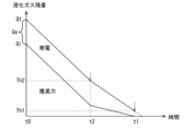
- FIG. 2 is a graph showing the change over time in the remaining amount of liquefied gas during navigation in this embodiment.
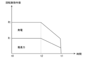
- FIG. 3 is a graph showing the change over time in the rotation speed command value accompanying the change over time in the remaining amount of liquefied gas shown in FIG. 2.
- time t0 indicates the position of the ship, i.e., the start time of the third control mode
- time t1 indicates the time of arrival at the dock.
- the ship maintains its current speed, and then decelerates from time t2.
- the propulsion system 1 is equipped with a controllable pitch propeller as the propulsion propeller 2.
- the propulsion force while the ship is sailing is changed by changing the blade angle of the propulsion propeller 2. Therefore, if the motor generator 4 is not operated and the driving force of the engine 3 is used only for the propulsion force of the ship, the rotation speed command value Ri of the engine 3 is set to a constant value during the constant speed sailing period from time t0 to time t2, as shown in FIG. 3.
- the provisional rotation speed command value Ri gradually decreases.
- the provisional rotation speed command value Ri may decrease in a stepwise manner. Also, when the ship decelerates until it stops by changing only the blade angle of the propulsion propeller 2, it is possible to control the provisional rotation speed command value Ri so that it does not change from the value at time t2.
- the required amount of liquefied gas Qi decreases over time. That is, since the amount of liquefied gas consumed per unit time is constant during the constant speed navigation period from time t0 to time t2, the required amount of liquefied gas Qi decreases linearly. During the deceleration period from time t2, the tentative rotation speed command value Ri decreases, thereby decreasing the amount of liquefied gas consumed per unit time, and therefore the decrease in the required amount of liquefied gas Qi becomes more gradual compared to the constant speed navigation period.
- the processing circuit 15 If the remaining amount of liquefied gas Qt at time t0 is greater than the required amount of liquefied gas Qi, the surplus amount of liquefied gas Qs, calculated by subtracting the required amount of liquefied gas Qi from the remaining amount of liquefied gas Qt, must be consumed by time t1 separately from the propulsive force of the ship. Therefore, the processing circuit 15 generates a rotation speed command value Rt for the engine 3 such that the remaining amount of liquefied gas Qt is equal to or less than a predetermined threshold value Th1 when the ship arrives at the dock.
- the actual rotation speed command value Rt in the third control mode will be greater than the provisional rotation speed command value Ri for generating the propulsive force of the ship, as shown in FIG. 3.
- the speed command value Rt during the constant speed navigation period is set to a constant value, similar to the provisional speed command value Ri.
- the speed command value Rt is set so that the remaining liquefied gas amount Qt becomes equal to or less than the threshold value Th1 by time t1.
- the speed command value Rt is set to monotonically decrease, but the speed command value Rt during the deceleration period may be set to a constant value, or may be set to a value that is increased from the constant speed navigation period.
- the rotation speed command value Rt may be set so that the amount of surplus liquefied gas Qs becomes equal to or less than the threshold value Th1 or becomes zero before time t1 is reached.
- the remaining amount of liquefied gas Qt may match the amount of required liquefied gas Qi between time t0 and time t1.
- the setting of the rotation speed command value Rt that may cause the liquefied gas to run out before arriving at the dock can be adopted in the case of a propulsion system 1 equipped with other thrust generating means such as a motor generator 4.
- the driving force of the engine 3 based on the rotation speed command value Rt set in this way is distributed between the propulsion force of the ship and the driving force for power generation.
- the processing circuit 15 generates a power converter command value for controlling the power that the first power converter 7 receives from the motor-generator 4 so that the motor-generator 4 generates electricity using the driving force of the engine 3 corresponding to the amount of surplus liquefied gas Qs.
- the amount of surplus liquefied gas Qs is converted into electricity by the engine 3 and the motor generator 4.
- the first power converter 7 converts the electricity supplied from the motor generator 4 into DC.
- the electricity generated using the amount of surplus liquefied gas Qs is charged to the battery 9 by the second power converter 8, which is connected to the DC wiring 6 via the second power converter 8.
- the electricity stored in the battery 9 is used, for example, as an onboard power source after the ship is docked.
- the electricity generated using the surplus liquefied gas amount Qs may be supplied to the AC wiring 11 connected to the DC wiring 6 via the third power converter 10, and consumed by the operation of the onboard load 13 connected to the AC wiring 11.
- the controller 14 may control the generator 12 connected to the AC wiring 11 to reduce the amount of power generated or to stop it.
- the onboard load 13 includes, for example, an electric boiler that generates steam used to vaporize the liquefied gas.
- electricity may be consumed by rotating the controllable pitch propeller with the blade angle of the controllable pitch propeller in the neutral position.
- the engine speed command value is controlled so that the remaining amount of liquefied gas will be depleted by the time the ship reaches the dock, and liquefied gas is consumed by the engine 3 taking into account the remaining amount of liquefied gas Qt.
- the surplus driving force excluding the driving force used to propel the ship is used to generate power by the motor generator 4.
- the amount of liquefied gas consumed per unit time is increased. This makes it possible to efficiently consume liquefied gas while generating power while sailing to the dock.
- the actual remaining liquefied gas amount Qt is not necessarily 0 immediately before docking, i.e., immediately before time t1.
- the threshold value Th1 of the remaining liquefied gas amount Qt may be set to a value greater than 0, so that the ship will navigate using the driving force of the engine 3 until it arrives at the dock.
- the required liquefied gas amount Qi is an estimated value, the amount of liquefied gas required to generate propulsive force for the ship until it actually arrives at the dock may change depending on the actual navigation environment, etc.
- the required liquefied gas amount Qi itself may be set to a value that includes a certain amount of margin.
- the processing circuit 15 before docking, for example when the ship enters a bay in a port where a dock is located, if the required amount of liquefied gas Qi remains in the tank 30, the processing circuit 15 generates a control command to consume the liquefied gas by driving the engine 3 while keeping the ship stationary.
- the processing circuit 15 may generate a control command to consume liquefied gas by rotating the propulsion propeller 2 using the driving force of the engine 3.
- the processing circuit 15 drives the engine 3 and controls the propulsion propeller 2, which is a variable pitch propeller, to alternate between a forward small angle and a reverse small angle. This allows at least a portion of the surplus liquefied gas amount Qs to be consumed by the driving force generated by the engine 3 while maintaining the ship stopped.
- the processing circuit 15 controls the engine 3 to be driven and the propulsion propeller 2 to rotate with the pair of left and right rudders 31 in the ship stopping position. This also allows at least a portion of the surplus liquefied gas amount Qs to be consumed by the driving force generated by the engine 3 while maintaining the ship stopped.
- the processing circuit 15 may drive the engine 3 while the ship is stopped, and control the direction of the rotation axis of the multiple slewing thrusters in a direction that maintains the ship's stopped state.
- the multiple slewing thrusters operate to cancel each other's thrust, so that the ship is maintained at a stop while the propulsion propeller 2 is driven. This also makes it possible to consume at least a portion of the surplus liquefied gas amount Qs by the driving force generated by the engine 3 while maintaining the ship at a stop.
- the engine 3 is driven based on a rotation speed command value that takes into account the remaining liquefied gas amount Qt during navigation, so that the liquefied gas is consumed efficiently, thereby shortening the amount of liquefied gas consumed while the ship is stopped and the time it takes to reduce the remaining liquefied gas amount Qt to zero. This makes it possible to realize a ship with a low environmental impact.
- the processing circuit 15 may correct the rotation speed command value Rt according to the degree of decrease in the actual remaining amount Qt of liquefied gas at a specified ship position after the rotation speed command value Rt was generated according to the above embodiment.
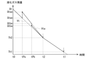
- FIG. 4 is a graph showing the change over time in the remaining amount of liquefied gas during navigation in a modified version of this embodiment.
- FIG. 5 is a graph showing the change over time in the rotation speed command value accompanying the change over time in the remaining amount of liquefied gas shown in FIG. 4.
- the rotation speed command value Rt is generated at time t0, and the third control mode is initiated.
- the processing circuit 15 acquires data on the remaining amount of liquefied gas Qtaa at a specified ship position Pa after time t0, which is the time when the rotation speed command value Rt is generated.
- the specified ship position Pa may be determined by the elapsed time from time t0, or by the distance from the ship's position at time t0, or may be a waypoint set on the route from the ship's position at time t0 to the dock. In Figures 4 and 5, the time when the ship reaches the ship position Pa is shown as tPa.
- the processing circuit 15 calculates the estimated remaining amount of liquefied gas Qtae at the ship's position Pa, which is estimated based on the rotation speed command value Rt.
- the estimated remaining amount of liquefied gas Qtae is calculated based on a function indicating an estimated value of the time change in the remaining amount of liquefied gas Qt when the rotation speed command value is Rt, and the time from time t0 to reaching the ship's position Pa.
- the remaining amount of liquefied gas at time tPa in the graph Vt in Figure 4 is the estimated remaining amount of liquefied gas Qtae.
- the processing circuit 15 calculates the difference between the actual liquefied gas remaining amount Qtaa and the estimated liquefied gas remaining amount Qtae at the ship position Pa.
- the actual liquefied gas remaining amount Qtaa is greater than the estimated liquefied gas remaining amount Qtae. In other words, it is determined that more liquefied gas remains at the ship position Pa than expected.
- the processing circuit 15 can correct the rotation speed command value Qt based on the difference between the actual liquefied gas remaining amount Qtaa and the estimated liquefied gas remaining amount Qtae at the ship position Pa. As shown in FIG.
- the processing circuit 15 corrects the rotation speed command value Rta to a value higher than the original rotation speed command value Rt in order to increase the liquefied gas consumption per unit time. Furthermore, the processing circuit 15 corrects the power converter command value based on the corrected rotation speed command value Rta.
- the processing circuit 15 corrects the rotation speed command value by multiplying the original rotation speed command value Rt by a predetermined coefficient, or by calculating the rotation speed command value Rta again as shown in the above embodiment.
- Multiple predetermined ship positions may be set.
- the rotation speed command value Rt is reviewed at the first ship position Pa and the second ship position Pb, which are defined as two ship positions.
- the processing circuit 15 also acquires data on the remaining amount of liquefied gas Qtba at the second ship position Pb, in the same way as at the first ship position Pa.
- the processing circuit 15 also calculates the estimated remaining amount of liquefied gas Qtbe at the second ship position Pb, which is estimated based on the rotation speed command value Rta.
- the estimated liquefied gas remaining amount Qtbe is calculated based on a function indicating an estimated value of the time change in the liquefied gas remaining amount Qt when the rotation speed command value is Rta, and the time from time tPa at the first ship position Pa to the time tPb when the second ship position Pb is reached. That is, the liquefied gas remaining amount at time tPb in the graph Vta in FIG. 4 becomes the estimated liquefied gas remaining amount Qtbe.
- the processing circuit 15 can correct the rotation speed command value Qta based on the difference between the actual liquefied gas remaining amount Qtba and the estimated liquefied gas remaining amount Qtbe at the second ship position Pb.
- the processing circuit 15 corrects the original rotation speed command value Rta to a lower rotation speed command value Rtb in order to reduce the amount of liquefied gas consumed per unit time. Furthermore, the processing circuit 15 corrects the power converter command value based on the corrected rotation speed command value Rtb.
- the rotation speed command value Rt is corrected according to the rate at which the actual remaining amount of liquefied gas Qt decreases after the rotation speed command value Rt is generated. This makes it possible to achieve consumption of liquefied gas that is neither excessive nor insufficient even if the actual operating conditions of the ship change after the rotation speed command value Rt is generated.
- the processing circuit 15 may correct the rotation speed command value Rt when the magnitude of the difference between the actual liquefied gas remaining amount Qtaa, Qtba and the estimated liquefied gas remaining amount Qtae, Qtbe at the ship positions Pa, Pb is equal to or greater than a predetermined reference value, and may not correct the rotation speed command value Rt when the magnitude of the difference is less than the predetermined reference value.
- the rotation speed command value Rt is corrected at the ship positions Pa, Pb during the constant speed navigation period from time t0 to time t2, but the rotation speed command value Rt may be corrected during the deceleration period from time t2 to time t1.
- a hybrid propulsion ship in which the engine 3 and the electric motor generator 4 can be used as driving force for the propulsion propeller 2 has been exemplified as the ship, but the present disclosure is not limited to this.
- the aspects of the present disclosure are applicable to a propulsion system 1 equipped with an engine that is driven by a fuel containing a fuel gas produced by vaporizing a liquefied gas as the engine 3. Therefore, the propulsion system does not need to be equipped with an electric motor generator 4 that generates driving force for the propulsion propeller 2. In this case, the propulsion system only needs to be equipped with a generator that can generate electricity using the driving force of the engine 3.
- the controller 14 in the ship is provided with a processing circuit 15 that performs various calculations in the third control mode, but the processing circuit 15 may be configured outside the ship.
- a management device installed on land may be configured to be able to communicate with the ship, and the management device may be provided with a processing circuit 15 that performs various calculations in the third control mode as part of the controller 14 that configures the ship's propulsion system 1.
- the threshold value of the remaining amount of liquefied gas Qt which is the reference for generating the rotation speed command value of the engine 3, is set as the value of the remaining amount of liquefied gas Qt immediately before arrival at the dock, i.e., as the threshold value Th1 at time t1.
- the time at which the amount of liquefied gas should be reduced to below the threshold value may be any time as long as it is a predetermined time before arrival at the dock.
- the time at which the amount of liquefied gas should be reduced to below the threshold value may be set to time t2, which is the end time of the constant speed navigation period.
- the processing circuit 15 may generate a rotation speed command value for the engine 3 such that the remaining amount of liquefied gas Qt is equal to or less than the threshold value Th2 at time t2.
- the user may be able to input the position coordinates at which the threshold value Th1 is set, the distance to the dock, or the time based on arrival at the dock, using the operation input device 16, and the time at which the amount of liquefied gas should be reduced to below the threshold value Th1 may be set based on the input content.
- the time when the threshold value Th1 should be set to be equal to or less than the threshold value Th1 is set to a specified time before the ship arrives at the dock, it is desirable that the ship have navigation capabilities other than navigation by consuming liquefied gas between the position at the time when the threshold value Th1 should be set to be equal to or less than the dock position. That is, in the case of a hybrid propulsion ship equipped with an electric motor generator 4 or an engine 3 that is a dual fuel engine, the time when the threshold value Th1 should be set to be equal to or less than the threshold value Th1 may be set to a specified time before the ship arrives at the dock.
- the time when the threshold value Th1 should be set to be equal to or less than the threshold value Th1 can also be set to a time before the ship arrives at the dock for ships that do not have navigation capabilities other than navigation by consuming liquefied gas.
- a hybrid propulsion vessel is illustrated with an engine 3 and a motor generator 4 connected in parallel to the propulsion propeller 2 via a reduction gear 5, but the mechanism for transmitting the driving force of the engine 3 and the motor generator 4 to the propulsion propeller 2 may be of any configuration as long as the motor generator 4 is capable of generating electricity using the driving force of the engine 3.
- control program in the above embodiment may be configured as a program product that is provided by downloading from an external computer, or recorded on a non-transitory computer-readable recording medium, or may be configured as a computer product with the control program pre-installed.
- a propulsion system is a ship propulsion system including a tank for storing liquefied gas, an engine driven by fuel containing fuel gas formed by vaporizing the liquefied gas and whose rotation speed is controlled according to a rotation speed command value, a generator mechanically connected to the engine and capable of generating electricity using the driving force of the engine, a power converter electrically connected to the generator, and a controller for controlling the engine and the power converter, the controller including a processing circuit, and the processing circuit is configured to receive and store information on a distance from a position of the ship to a dock where the ship will be docked, the speed of the ship, and the amount of liquefied gas remaining in the tank.
- a required amount of liquefied gas indicating the amount of liquefied gas necessary for the ship to navigate to the dock using the engine using the distance and the speed
- calculate an amount of surplus liquefied gas by subtracting the required amount of liquefied gas from the remaining amount of liquefied gas
- generate the rotation speed command value for the engine such that the remaining amount of liquefied gas becomes equal to or less than a predetermined threshold value at a predetermined time before arriving at the dock
- a power converter command value for controlling the power that the power converter receives from the generator so that the generator generates power using the driving force of the engine corresponding to the amount of surplus liquefied gas.
- the engine speed command value is controlled so that there is no remaining liquefied gas by the time the ship reaches the dock, and the liquefied gas is consumed by the engine.
- the surplus driving force generated by the engine excluding the driving force used to propel the ship, is used to generate electricity by the generator. This makes it possible to efficiently consume liquefied gas while generating electricity during the ship's sailing to the dock.
- the processing circuit may obtain data on the remaining amount of liquefied gas at a predetermined ship position after the time when the rotation speed command value is generated, calculate an estimated remaining amount of liquefied gas at the ship position estimated based on the rotation speed command value, and correct the rotation speed command value based on a difference between the remaining amount of liquefied gas at the ship position and the estimated remaining amount of liquefied gas. According to this, the rotation speed command value is corrected according to the actual decrease in the remaining amount of liquefied gas after the rotation speed command value is generated. Therefore, it is possible to realize consumption of liquefied gas without excess or deficiency even if the actual operating state of the ship changes after the rotation speed command value is generated.
- the propulsion system of item 1 or 2 may further include a capacitor electrically connected to the power converter, the capacitor being charged by the power received from the generator.
- the propulsion system of any one of items 1 to 3 may further include an onboard load electrically connected to the power converter, the onboard load being operated by the power received from the generator.
- the propulsion system may include a propulsion propeller mechanically connected to the engine, the propulsion propeller including a controllable pitch propeller mechanically connected to the engine and capable of changing a blade angle according to a blade angle command value, and the processing circuit may drive the engine while the ship is stopped, and control the controllable pitch propeller to alternately change between a forward small angle and a reverse small angle, thereby consuming at least a portion of the surplus liquefied gas by the driving force generated by the engine while maintaining the ship stopped. In this way, even if there is a remaining amount of liquefied gas when the ship approaches a dock, the liquefied gas can be quickly consumed while the ship is stopped.
- the propulsion system according to any one of items 1 to 5, further comprising: a propulsion propeller mechanically connected to the engine; and a pair of left and right rudders arranged rearward or to the sides of the propulsion propeller;
- the processing circuit may drive the engine when the ship is stopped, and control the propulsion propellers to rotate with the pair of left and right rudders in the stopped position, thereby consuming at least a portion of the excess liquefied gas by the driving force generated by the engine while maintaining the ship stopped.
- Any of the propulsion systems of items 1 to 4 may include a propulsion propeller mechanically connected to the engine, the propulsion propeller including a plurality of slewing thrusters capable of changing the direction of the propeller's rotational axis, and the processing circuit may drive the engine when the ship is stopped, and control the direction of the rotational axes of the plurality of slewing thrusters in a direction that maintains the ship's stopped state, thereby consuming at least a portion of the excess liquefied gas by the driving force generated by the engine while maintaining the ship's stopped state.
- a control program is a control program for a ship including a tank for storing liquefied gas, an engine driven by fuel including fuel gas obtained by vaporizing the liquefied gas and whose rotation speed is controlled according to a rotation speed command value, a generator mechanically connected to the engine and capable of generating electricity by using the driving force of the engine, a power converter electrically connected to the generator, and a controller for controlling the engine and the power converter, the control program instructing the controller to obtain a distance from a position of the ship to a dock where the ship is to be docked, a speed of the ship, and an amount of liquefied gas remaining in the tank, and using the speed, estimate a required amount of liquefied gas indicating the amount of liquefied gas necessary for the ship to navigate to the dock using the engine; calculate an amount of surplus liquefied gas by subtracting the required amount of liquefied gas from the remaining amount of liquefied gas; generate the rotation speed command value for the
- a control method is a control method for a ship including a tank for storing liquefied gas, an engine driven by fuel including fuel gas obtained by vaporizing the liquefied gas and whose rotation speed is controlled in accordance with a rotation speed command value, a generator mechanically connected to the engine and capable of generating electricity using the driving force of the engine, a power converter electrically connected to the generator, and a controller for controlling the engine and the power converter, the control method comprising the steps of: acquiring a distance from a position of the ship to a dock where the ship is to be docked, the speed of the ship, and a remaining amount of liquefied gas in the tank; estimating a required amount of liquefied gas indicating an amount of liquefied gas required for the ship to navigate to the dock using the engine, using the distance and the speed; calculating an amount of surplus liquefied gas by subtracting the required amount of liquefied gas from the remaining amount of liquefied gas;
Landscapes
- Engineering & Computer Science (AREA)
- Chemical & Material Sciences (AREA)
- Combustion & Propulsion (AREA)
- Mechanical Engineering (AREA)
- Ocean & Marine Engineering (AREA)
- Aviation & Aerospace Engineering (AREA)
- Filling Or Discharging Of Gas Storage Vessels (AREA)
- Control Of Vehicle Engines Or Engines For Specific Uses (AREA)
Abstract
Description
り具体的には、処理回路15は、プロセッサ、記憶器および周辺回路を含む。プロセッサは、例えば、CPUまたはMPU等を含む。記憶器は、ROM、RAM、レジスタ、不揮発性のストレージ等を含む。周辺回路は、入出力インターフェイス等を含む。制御器14は、船舶を操作する操作入力器16に接続される。制御器14は、制御状態を表示するモニタまたは音声出力を行うスピーカ等に接続されてもよい。
例えば、処理回路15は、上記実施の形態に従って回転数指令値Rtを生成した時点以後の所定の船舶位置における実際の液化ガス残量Qtの減り具合に応じて回転数指令値Rtを補正してもよい。
[項目1]
本開示の一態様に係る推進システムは、液化ガスを貯留するタンクと、前記液化ガスを気化した燃料ガスを含む燃料で駆動し、回転数指令値に従って回転数が制御されるエンジンと、前記エンジンに機械的に接続され、前記エンジンの駆動力を利用して発電可能な発電機と、前記発電機に電気的に接続される電力変換器と、前記エンジンおよび前記電力変換器を制御する制御器と、を備えた船舶の推進システムであって、前記制御器は、処理回路を含み、前記処理回路は、前記船舶の位置から入渠先のドックまでの距離、前記船舶の速度、および前記タンク内の液化ガス残量を取得し、前記距離および前記速度を用いて、前記船舶が前記ドックまで前記エンジンで航行するために必要な液化ガスの量を示す必要液化ガス量を推定し、前記液化ガス残量から前記必要液化ガス量を差し引いた余剰液化ガス量を算出し、前記ドックに到着する前の所定の時点で前記液化ガス残量が所定のしきい値以下になるような前記エンジンに対する前記回転数指令値を生成し、前記発電機が前記余剰液化ガス量に対応する前記エンジンの駆動力を用いて発電するように、前記電力変換器が前記発電機から受け取る電力を制御するための電力変換器指令値を生成する。
項目1の推進システムにおいて、前記処理回路は、前記回転数指令値を生成した時点以後の所定の船舶位置における前記液化ガス残量のデータを取得し、前記回転数指令値に基づいて推定される前記船舶位置での推定液化ガス残量を算出し、前記船舶位置における前記液化ガス残量と前記推定液化ガス残量との差分に基づいて、前記回転数指令値を補正してもよい。これによれば、回転数指令値生成後において実際の液化ガス残量の減り具合に応じて回転数指令値が補正される。このため、回転数指令値生成後の船舶の実際の運航状態が変化しても過不足のない液化ガスの消費を実現することができる。
項目1または2の推進システムは、前記電力変換器に電気的に接続される蓄電器を備え、前記蓄電器は、前記発電機から受け取った電力により充電されてもよい。
項目1から3の何れかの推進システムは、前記電力変換器に電気的に接続される船内負荷を備え、前記船内負荷は、前記発電機から受け取った電力により動作してもよい。
項目1から4の何れかの推進システムは、前記エンジンに機械的に接続された推進プロペラを備え、前記推進プロペラは、前記エンジンに機械的に接続され、翼角指令値に従って翼角を変更可能な可変ピッチプロペラを含み、前記処理回路は、停船状態において、前記エンジンを駆動し、かつ、前記可変ピッチプロペラを前進側微小角および後進側微小角の間で交互に変化させるように制御することにより、前記停船状態を保持しつつ前記余剰液化ガス量の少なくとも一部を前記エンジンで生じる駆動力により消費させてもよい。これによれば、ドックに近づいた段階で液化ガス残量が残っていても船舶を停止した状態で液化ガスを迅速に消費することができる。
項目1から5の何れかの推進システムは、前記エンジンに機械的に接続された推進プロペラと、前記推進プロペラの後方または側方に配置された左右一対の舵と、を備え、
前記処理回路は、停船状態において、前記エンジンを駆動し、かつ、前記左右一対の舵を停船位置とした状態で前記推進プロペラを回転させるように制御することにより、前記停船状態を保持しつつ前記余剰液化ガス量の少なくとも一部を前記エンジンで生じる駆動力により消費させてもよい。
項目1から4の何れかの推進システムは、前記エンジンに機械的に接続された推進プロペラを備え、前記推進プロペラは、プロペラの回転軸方向を変更可能な複数の旋回式スラスタを含み、前記処理回路は、停船状態において、前記エンジンを駆動し、かつ、前記複数の旋回式スラスタの回転軸方向を停船状態を保持する方向に制御することにより、前記停船状態を保持しつつ前記余剰液化ガス量の少なくとも一部を前記エンジンで生じる駆動力により消費させてもよい。
本開示の他の態様に係る制御プログラムは、液化ガスを貯留するタンクと、前記液化ガスを気化した燃料ガスを含む燃料で駆動し、回転数指令値に従って回転数が制御されるエンジンと、前記エンジンに機械的に接続され、前記エンジンの駆動力を利用して発電可能な発電機と、前記発電機に電気的に接続される電力変換器と、前記エンジンおよび前記電力変換器を制御する制御器と、を備えた船舶の制御プログラムであって、前記制御プログラムは、前記制御器に、前記船舶の位置から入渠先のドックまでの距離、前記船舶の速度、および前記タンク内の液化ガス残量を取得すること、前記距離および前記速度を用いて、前記船舶が前記ドックまで前記エンジンで航行するために必要な液化ガスの量を示す必要液化ガス量を推定すること、前記液化ガス残量から前記必要液化ガス量を差し引いた余剰液化ガス量を算出すること、前記ドックに到着する前の所定の時点で前記液化ガス残量が所定のしきい値以下になるような前記エンジンに対する前記回転数指令値を生成すること、および前記発電機が前記余剰液化ガス量に対応する前記エンジンの駆動力を用いて発電するように、前記電力変換器が前記発電機から受け取る電力を制御するための電力変換器指令値を生成することを行わせる。
本開示の他の態様に係る制御方法は、液化ガスを貯留するタンクと、前記液化ガスを気化した燃料ガスを含む燃料で駆動し、回転数指令値に従って回転数が制御されるエンジンと、前記エンジンに機械的に接続され、前記エンジンの駆動力を利用して発電可能な発電機と、前記発電機に電気的に接続される電力変換器と、前記エンジンおよび前記電力変換器を制御する制御器と、を備えた船舶の制御方法であって、前記船舶の位置から入渠先のドックまでの距離、前記船舶の速度、および前記タンク内の液化ガス残量を取得し、前記距離および前記速度を用いて、前記船舶が前記ドックまで前記エンジンで航行するために必要な液化ガスの量を示す必要液化ガス量を推定し、前記液化ガス残量から前記必要液化ガス量を差し引いた余剰液化ガス量を算出し、前記ドックに到着する前の所定の時点で前記液化ガス残量が所定のしきい値以下になるような前記エンジンに対する前記回転数指令値を生成し、前記発電機が前記余剰液化ガス量に対応する前記エンジンの駆動力を用いて発電するように、前記電力変換器が前記発電機から受け取る電力を制御するための電力変換器指令値を生成する。
2 推進プロペラ
3 エンジン
4 電動発電機(発電機)
7 第1電力変換器(電力変換器)
9 蓄電器
13 船内負荷
14 制御器
15 処理回路
30 タンク
31 舵
Claims (9)
- 液化ガスを貯留するタンクと、
前記液化ガスを気化した燃料ガスを含む燃料で駆動し、回転数指令値に従って回転数が制御されるエンジンと、
前記エンジンに機械的に接続され、前記エンジンの駆動力を利用して発電可能な発電機と、
前記発電機に電気的に接続される電力変換器と、
前記エンジンおよび前記電力変換器を制御する制御器と、を備えた船舶の推進システムであって、
前記制御器は、処理回路を含み、
前記処理回路は、
前記船舶の位置から入渠先のドックまでの距離、前記船舶の速度、および前記タンク内の液化ガス残量についてのデータを取得し、
前記距離および前記速度を用いて、前記船舶が前記ドックまで前記エンジンで航行するために必要な液化ガスの量を示す必要液化ガス量を推定し、
前記液化ガス残量から前記必要液化ガス量を差し引いた余剰液化ガス量を算出し、
前記ドックに到着する前の所定の時点で前記液化ガス残量が所定のしきい値以下になるような前記エンジンに対する前記回転数指令値を生成し、
前記発電機が前記余剰液化ガス量に対応する前記エンジンの駆動力を用いて発電するように、前記電力変換器が前記発電機から受け取る電力を制御するための電力変換器指令値を生成する、推進システム。 - 前記処理回路は、
前記回転数指令値を生成した時点以後の所定の船舶位置における前記液化ガス残量のデータを取得し、
前記回転数指令値に基づいて推定される前記船舶位置での推定液化ガス残量を算出し、
前記船舶位置における前記液化ガス残量と前記推定液化ガス残量との差分に基づいて、前記回転数指令値を補正する、請求項1に記載の推進システム。 - 前記電力変換器に電気的に接続される蓄電器を備え、
前記蓄電器は、前記発電機から受け取った電力により充電される、請求項1または2に記載の推進システム。 - 前記電力変換器に電気的に接続される船内負荷を備え、
前記船内負荷は、前記発電機から受け取った電力により動作する、請求項1または2に記載の推進システム。 - 前記エンジンに機械的に接続された推進プロペラを備え、
前記推進プロペラは、翼角指令値に従って翼角を変更可能な可変ピッチプロペラを含み、
前記処理回路は、停船状態において、前記エンジンを駆動し、かつ、前記可変ピッチプロペラを前進側微小角および後進側微小角の間で交互に変化させるように制御することにより、前記停船状態を保持しつつ前記余剰液化ガス量の少なくとも一部を前記エンジンで生じる駆動力により消費させる、請求項1または2に記載の推進システム。 - 前記エンジンに機械的に接続された推進プロペラと、
前記推進プロペラの後方または側方に配置された左右一対の舵と、を備え、
前記処理回路は、停船状態において、前記エンジンを駆動し、かつ、前記左右一対の舵を停船位置とした状態で前記推進プロペラを回転させるように制御することにより、前記停船状態を保持しつつ前記余剰液化ガス量の少なくとも一部を前記エンジンで生じる駆動力により消費させる、請求項1または2に記載の推進システム。 - 前記エンジンに機械的に接続された推進プロペラを備え、
前記推進プロペラは、プロペラの回転軸方向を変更可能な複数の旋回式スラスタを含み、
前記処理回路は、停船状態において、前記エンジンを駆動し、かつ、前記複数の旋回式スラスタの回転軸方向を停船状態を保持する方向に制御することにより、前記停船状態を保持しつつ前記余剰液化ガス量の少なくとも一部を前記エンジンで生じる駆動力により消費させる、請求項1または2に記載の推進システム。 - 液化ガスを貯留するタンクと、
前記液化ガスを気化した燃料ガスを含む燃料で駆動し、回転数指令値に従って回転数が制御されるエンジンと、
前記エンジンに機械的に接続され、前記エンジンの駆動力を利用して発電可能な発電機と、
前記発電機に電気的に接続される電力変換器と、
前記エンジンおよび前記電力変換器を制御する制御器と、を備えた船舶の制御プログラムであって、
前記制御プログラムは、前記制御器に、
前記船舶の位置から入渠先のドックまでの距離、前記船舶の速度、および前記タンク内の液化ガス残量についてのデータを取得すること、
前記距離および前記速度を用いて、前記船舶が前記ドックまで前記エンジンで航行するために必要な液化ガスの量を示す必要液化ガス量を推定すること、
前記液化ガス残量から前記必要液化ガス量を差し引いた余剰液化ガス量を算出すること、
前記ドックに到着する前の所定の時点で前記液化ガス残量が所定のしきい値以下になるような前記エンジンに対する前記回転数指令値を生成すること、および
前記発電機が前記余剰液化ガス量に対応する前記エンジンの駆動力を用いて発電するように、前記電力変換器が前記発電機から受け取る電力を制御するための電力変換器指令値を生成することを行わせる、制御プログラム。 - 液化ガスを貯留するタンクと、
前記液化ガスを気化した燃料ガスを含む燃料で駆動し、回転数指令値に従って回転数が制御されるエンジンと、
前記エンジンに機械的に接続され、前記エンジンの駆動力を利用して発電可能な発電機と、
前記発電機に電気的に接続される電力変換器と、
前記エンジンおよび前記電力変換器を制御する制御器と、を備えた船舶の制御方法であって、
前記船舶の位置から入渠先のドックまでの距離、前記船舶の速度、および前記タンク内の液化ガス残量についてのデータを取得し、
前記距離および前記速度を用いて、前記船舶が前記ドックまで前記エンジンで航行するために必要な液化ガスの量を示す必要液化ガス量を推定し、
前記液化ガス残量から前記必要液化ガス量を差し引いた余剰液化ガス量を算出し、
前記ドックに到着する前の所定の時点で前記液化ガス残量が所定のしきい値以下になるような前記エンジンに対する前記回転数指令値を生成し、
前記発電機が前記余剰液化ガス量に対応する前記エンジンの駆動力を用いて発電するように、前記電力変換器が前記発電機から受け取る電力を制御するための電力変換器指令値を生成する、制御方法。
Priority Applications (2)
| Application Number | Priority Date | Filing Date | Title |
|---|---|---|---|
| CN202480017486.1A CN120858054A (zh) | 2023-03-14 | 2024-02-13 | 推进系统、控制程序以及控制方法 |
| KR1020257029872A KR20250145073A (ko) | 2023-03-14 | 2024-02-13 | 추진 시스템, 제어 프로그램 및 제어 방법 |
Applications Claiming Priority (2)
| Application Number | Priority Date | Filing Date | Title |
|---|---|---|---|
| JP2023039372A JP2024129949A (ja) | 2023-03-14 | 2023-03-14 | 推進システム、制御プログラムおよび制御方法 |
| JP2023-039372 | 2023-03-14 |
Publications (1)
| Publication Number | Publication Date |
|---|---|
| WO2024190232A1 true WO2024190232A1 (ja) | 2024-09-19 |
Family
ID=92755370
Family Applications (1)
| Application Number | Title | Priority Date | Filing Date |
|---|---|---|---|
| PCT/JP2024/004872 Ceased WO2024190232A1 (ja) | 2023-03-14 | 2024-02-13 | 推進システム、制御プログラムおよび制御方法 |
Country Status (4)
| Country | Link |
|---|---|
| JP (1) | JP2024129949A (ja) |
| KR (1) | KR20250145073A (ja) |
| CN (1) | CN120858054A (ja) |
| WO (1) | WO2024190232A1 (ja) |
Citations (7)
| Publication number | Priority date | Publication date | Assignee | Title |
|---|---|---|---|---|
| JP2005022650A (ja) * | 2004-09-21 | 2005-01-27 | National Maritime Research Institute | ハイブリッド型舶用推進装置 |
| JP2015175470A (ja) * | 2014-03-17 | 2015-10-05 | 三井造船株式会社 | 液化ガス運搬船の再液化装置 |
| JP2016137894A (ja) * | 2016-04-25 | 2016-08-04 | 三井造船株式会社 | 液化ガス運搬船用燃料ガス供給システム |
| JP2017025791A (ja) * | 2015-07-23 | 2017-02-02 | パーパス株式会社 | ガスエンジン発電機、その制御プログラム、その記録媒体およびその制御方法 |
| KR20190127170A (ko) * | 2018-05-03 | 2019-11-13 | 한국조선해양 주식회사 | 운영 관리 시스템 및 이를 포함하는 선박 |
| KR20200050481A (ko) * | 2018-10-31 | 2020-05-12 | 삼성중공업 주식회사 | 선박의 연료가스 관리시스템 |
| JP2022011720A (ja) * | 2020-06-30 | 2022-01-17 | 三井E&S造船株式会社 | 電気推進船の推進機構及び電気推進船 |
Family Cites Families (1)
| Publication number | Priority date | Publication date | Assignee | Title |
|---|---|---|---|---|
| KR102256533B1 (ko) | 2018-12-14 | 2021-05-25 | 경남대학교 산학협력단 | 단위셀 및 단위셀을 포함하는 샌드위치 판재 |
-
2023
- 2023-03-14 JP JP2023039372A patent/JP2024129949A/ja active Pending
-
2024
- 2024-02-13 CN CN202480017486.1A patent/CN120858054A/zh active Pending
- 2024-02-13 KR KR1020257029872A patent/KR20250145073A/ko active Pending
- 2024-02-13 WO PCT/JP2024/004872 patent/WO2024190232A1/ja not_active Ceased
Patent Citations (7)
| Publication number | Priority date | Publication date | Assignee | Title |
|---|---|---|---|---|
| JP2005022650A (ja) * | 2004-09-21 | 2005-01-27 | National Maritime Research Institute | ハイブリッド型舶用推進装置 |
| JP2015175470A (ja) * | 2014-03-17 | 2015-10-05 | 三井造船株式会社 | 液化ガス運搬船の再液化装置 |
| JP2017025791A (ja) * | 2015-07-23 | 2017-02-02 | パーパス株式会社 | ガスエンジン発電機、その制御プログラム、その記録媒体およびその制御方法 |
| JP2016137894A (ja) * | 2016-04-25 | 2016-08-04 | 三井造船株式会社 | 液化ガス運搬船用燃料ガス供給システム |
| KR20190127170A (ko) * | 2018-05-03 | 2019-11-13 | 한국조선해양 주식회사 | 운영 관리 시스템 및 이를 포함하는 선박 |
| KR20200050481A (ko) * | 2018-10-31 | 2020-05-12 | 삼성중공업 주식회사 | 선박의 연료가스 관리시스템 |
| JP2022011720A (ja) * | 2020-06-30 | 2022-01-17 | 三井E&S造船株式会社 | 電気推進船の推進機構及び電気推進船 |
Also Published As
| Publication number | Publication date |
|---|---|
| JP2024129949A (ja) | 2024-09-30 |
| CN120858054A (zh) | 2025-10-28 |
| KR20250145073A (ko) | 2025-10-13 |
Similar Documents
| Publication | Publication Date | Title |
|---|---|---|
| KR101712474B1 (ko) | 전기 추진 선박용 제어 장치 | |
| JP5164042B2 (ja) | 船舶エネルギーシステム | |
| WO2017135199A1 (ja) | 船舶の電力システム | |
| JP7445564B2 (ja) | 制御装置、制御方法及びプログラム | |
| JP6044922B2 (ja) | 船舶のハイブリッド運航システムおよびハイブリッド運航船 | |
| US12249858B2 (en) | Marine propulsion system and marine power supply system including a plurality of batteries | |
| CN102458979A (zh) | 用于控制推进系统的方法和系统 | |
| JP2013209018A5 (ja) | ||
| JP2023115833A (ja) | 船舶の制御システム及び制御方法 | |
| US11459077B2 (en) | Marine power supply system and method for power control in marine propulsion system | |
| JP2016222149A (ja) | 船舶及び船内電力系統への電力供給方法 | |
| JP2024129949A (ja) | 推進システム、制御プログラムおよび制御方法 | |
| JP2007284018A (ja) | 船舶用ハイブリッド推進システム | |
| KR20220053713A (ko) | 스러스터 제어 시스템 | |
| JP2013163486A (ja) | 舶用推進装置の制御装置 | |
| US20170283025A1 (en) | Marine vessel power system and method | |
| JP6677682B2 (ja) | ハイブリッド推進式船舶 | |
| KR101637335B1 (ko) | 부유식 구조물의 전력 관리 시스템 및 그의 전력 관리 방법 | |
| JP2016094193A (ja) | 船舶推進装置の制御装置 | |
| JP2025110493A (ja) | 船舶の推進システム、制御プログラムおよび制御方法 | |
| CN120813522A (zh) | 混合动力推进船的推进系统、控制程序以及控制方法 | |
| JP2025008805A (ja) | 船舶の推進システム、制御プログラムおよび制御方法 | |
| WO2020144759A1 (ja) | ハイブリッド推進船の運航方法及びハイブリッド推進船 | |
| EP4737303A1 (en) | Display device and ship | |
| KR20260007086A (ko) | 선박 추진 시스템 |
Legal Events
| Date | Code | Title | Description |
|---|---|---|---|
| 121 | Ep: the epo has been informed by wipo that ep was designated in this application |
Ref document number: 24770349 Country of ref document: EP Kind code of ref document: A1 |
|
| ENP | Entry into the national phase |
Ref document number: 1020257029872 Country of ref document: KR Free format text: ST27 STATUS EVENT CODE: A-0-1-A10-A15-NAP-PA0105 (AS PROVIDED BY THE NATIONAL OFFICE) |
|
| WWE | Wipo information: entry into national phase |
Ref document number: CN2024800174861 Country of ref document: CN Ref document number: 202480017486.1 Country of ref document: CN |
|
| WWP | Wipo information: published in national office |
Ref document number: 1020257029872 Country of ref document: KR |
|
| NENP | Non-entry into the national phase |
Ref country code: DE |
|
| WWP | Wipo information: published in national office |
Ref document number: 202480017486.1 Country of ref document: CN |
|
| 122 | Ep: pct application non-entry in european phase |
Ref document number: 24770349 Country of ref document: EP Kind code of ref document: A1 |