WO2024190065A1 - 駆動装置、信号処理装置、超音波センサ、及び車両 - Google Patents
駆動装置、信号処理装置、超音波センサ、及び車両 Download PDFInfo
- Publication number
- WO2024190065A1 WO2024190065A1 PCT/JP2024/001139 JP2024001139W WO2024190065A1 WO 2024190065 A1 WO2024190065 A1 WO 2024190065A1 JP 2024001139 W JP2024001139 W JP 2024001139W WO 2024190065 A1 WO2024190065 A1 WO 2024190065A1
- Authority
- WO
- WIPO (PCT)
- Prior art keywords
- frequency
- drive
- transmission signal
- sequence
- vibration element
- Prior art date
- Legal status (The legal status is an assumption and is not a legal conclusion. Google has not performed a legal analysis and makes no representation as to the accuracy of the status listed.)
- Ceased
Links
Images

Classifications
-
- G—PHYSICS
- G01—MEASURING; TESTING
- G01S—RADIO DIRECTION-FINDING; RADIO NAVIGATION; DETERMINING DISTANCE OR VELOCITY BY USE OF RADIO WAVES; LOCATING OR PRESENCE-DETECTING BY USE OF THE REFLECTION OR RERADIATION OF RADIO WAVES; ANALOGOUS ARRANGEMENTS USING OTHER WAVES
- G01S15/00—Systems using the reflection or reradiation of acoustic waves, e.g. sonar systems
- G01S15/02—Systems using the reflection or reradiation of acoustic waves, e.g. sonar systems using reflection of acoustic waves
- G01S15/06—Systems determining the position data of a target
- G01S15/08—Systems for measuring distance only
- G01S15/10—Systems for measuring distance only using transmission of interrupted, pulse-modulated waves
- G01S15/102—Systems for measuring distance only using transmission of interrupted, pulse-modulated waves using transmission of pulses having some particular characteristics
-
- G—PHYSICS
- G01—MEASURING; TESTING
- G01S—RADIO DIRECTION-FINDING; RADIO NAVIGATION; DETERMINING DISTANCE OR VELOCITY BY USE OF RADIO WAVES; LOCATING OR PRESENCE-DETECTING BY USE OF THE REFLECTION OR RERADIATION OF RADIO WAVES; ANALOGOUS ARRANGEMENTS USING OTHER WAVES
- G01S15/00—Systems using the reflection or reradiation of acoustic waves, e.g. sonar systems
- G01S15/02—Systems using the reflection or reradiation of acoustic waves, e.g. sonar systems using reflection of acoustic waves
- G01S15/06—Systems determining the position data of a target
- G01S15/08—Systems for measuring distance only
- G01S15/32—Systems for measuring distance only using transmission of continuous waves, whether amplitude-, frequency-, or phase-modulated, or unmodulated
-
- G—PHYSICS
- G01—MEASURING; TESTING
- G01S—RADIO DIRECTION-FINDING; RADIO NAVIGATION; DETERMINING DISTANCE OR VELOCITY BY USE OF RADIO WAVES; LOCATING OR PRESENCE-DETECTING BY USE OF THE REFLECTION OR RERADIATION OF RADIO WAVES; ANALOGOUS ARRANGEMENTS USING OTHER WAVES
- G01S15/00—Systems using the reflection or reradiation of acoustic waves, e.g. sonar systems
- G01S15/88—Sonar systems specially adapted for specific applications
- G01S15/93—Sonar systems specially adapted for specific applications for anti-collision purposes
- G01S15/931—Sonar systems specially adapted for specific applications for anti-collision purposes of land vehicles
-
- G—PHYSICS
- G01—MEASURING; TESTING
- G01S—RADIO DIRECTION-FINDING; RADIO NAVIGATION; DETERMINING DISTANCE OR VELOCITY BY USE OF RADIO WAVES; LOCATING OR PRESENCE-DETECTING BY USE OF THE REFLECTION OR RERADIATION OF RADIO WAVES; ANALOGOUS ARRANGEMENTS USING OTHER WAVES
- G01S7/00—Details of systems according to groups G01S13/00, G01S15/00, G01S17/00
- G01S7/52—Details of systems according to groups G01S13/00, G01S15/00, G01S17/00 of systems according to group G01S15/00
- G01S7/523—Details of pulse systems
- G01S7/524—Transmitters
-
- G—PHYSICS
- G01—MEASURING; TESTING
- G01S—RADIO DIRECTION-FINDING; RADIO NAVIGATION; DETERMINING DISTANCE OR VELOCITY BY USE OF RADIO WAVES; LOCATING OR PRESENCE-DETECTING BY USE OF THE REFLECTION OR RERADIATION OF RADIO WAVES; ANALOGOUS ARRANGEMENTS USING OTHER WAVES
- G01S7/00—Details of systems according to groups G01S13/00, G01S15/00, G01S17/00
- G01S7/52—Details of systems according to groups G01S13/00, G01S15/00, G01S17/00 of systems according to group G01S15/00
- G01S7/534—Details of non-pulse systems
-
- G—PHYSICS
- G01—MEASURING; TESTING
- G01S—RADIO DIRECTION-FINDING; RADIO NAVIGATION; DETERMINING DISTANCE OR VELOCITY BY USE OF RADIO WAVES; LOCATING OR PRESENCE-DETECTING BY USE OF THE REFLECTION OR RERADIATION OF RADIO WAVES; ANALOGOUS ARRANGEMENTS USING OTHER WAVES
- G01S7/00—Details of systems according to groups G01S13/00, G01S15/00, G01S17/00
- G01S7/52—Details of systems according to groups G01S13/00, G01S15/00, G01S17/00 of systems according to group G01S15/00
- G01S7/534—Details of non-pulse systems
- G01S7/536—Extracting wanted echo signals
Definitions
- the invention disclosed in this specification relates to a drive unit, a signal processing unit, an ultrasonic sensor, and a vehicle.
- the ultrasonic sensor generates ultrasonic waves, measures the time it takes for the ultrasonic waves to hit an object and return to the ultrasonic sensor, and uses the measured time to calculate the distance from the ultrasonic sensor to the object.
- the ultrasonic sensor disclosed in Patent Document 1 changes the frequency of the transmitted signal and identifies the reflected wave by determining how the frequency changes.
- the frequency of the ultrasonic vibration element does not change immediately in response to the frequency change of the transmitted signal. In this way, if the vibration frequency change of the ultrasonic vibration element does not follow the frequency change of the transmitted signal well, the accuracy of identifying the reflected wave may deteriorate unless the frequency change is made gradual and the driving period of the ultrasonic vibration element is extended.
- the driving device includes a transmission signal generating circuit configured to generate a transmission signal, and a driving circuit configured to drive an ultrasonic vibration element based on the transmission signal.
- the driving circuit includes an initial driving sequence that generates the transmission signal at an initial frequency, a first transition sequence that generates the transmission signal from the initial frequency until it transitions to a first frequency, and a second transition sequence that generates the transmission signal from the first frequency until it transitions to a second frequency.
- the initial frequency and the second frequency are closer to the resonant frequency of the ultrasonic vibration element than the first frequency.
- the duration of the first transition sequence is longer than the duration of the second transition sequence.
- the signal processing device includes a drive device having the above-described configuration, a receiving circuit configured to generate a received signal based on a reflected wave, which is an ultrasonic wave transmitted from the ultrasonic vibration element and reflected by an object, and an identification circuit configured to identify the reflected wave from the received signal.
- the ultrasonic sensor disclosed herein comprises a signal processing device having the above configuration and an ultrasonic transmission/reception device including the ultrasonic vibration element.
- the vehicle disclosed herein is equipped with an ultrasonic sensor having the above configuration.
- the ultrasonic vibration element it is possible to improve the ability of the ultrasonic vibration element to follow changes in vibration frequency in response to changes in the frequency of the transmission signal while preventing the drive period of the ultrasonic vibration element from becoming longer. This makes it possible to improve the accuracy of identifying reflected waves even if the drive period of the ultrasonic vibration element is short.
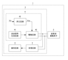
- FIG. 1 is a diagram showing a schematic configuration of an ultrasonic sensor according to an embodiment.
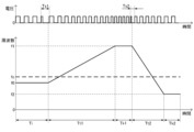
- FIG. 2 is a diagram showing the waveform of a drive signal and the frequency transition of a transmission signal.
- FIG. 3 is a diagram showing other waveforms of the drive signal and frequency transitions of the transmission signal.
- FIG. 4 is a diagram showing a first pattern of frequency transition of a transmission signal and an ultrasonic wave.
- FIG. 5 is a diagram showing a second pattern of frequency transition of the transmission signal and the ultrasonic wave.
- FIG. 6 is a diagram showing a third pattern of frequency transition of a transmission signal and an ultrasonic wave.
- FIG. 7 is a diagram showing a fourth pattern of frequency transition of a transmission signal and an ultrasonic wave.
- FIG. 8 is a diagram showing a fifth pattern of frequency transition of a transmission signal and an ultrasonic wave.
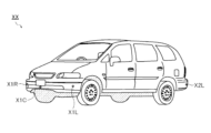
- FIG. 9 is an external view of the vehicle.
- FIG. 1 is a diagram showing the schematic configuration of an ultrasonic sensor 1 according to an embodiment.
- the ultrasonic sensor 1 includes an ultrasonic vibration element 2 and a signal processing device 3.
- the ultrasonic vibration element 2 is composed of a piezoelectric element, and emits ultrasonic waves and receives ultrasonic waves reflected by an object (waves reflected from an object).
- the ultrasonic vibration element 2 is an ultrasonic transmission/reception device that transmits and receives ultrasonic waves.
- the ultrasonic sensor may be configured to include an ultrasonic vibration element dedicated to transmitting ultrasonic waves and an ultrasonic vibration element dedicated to receiving ultrasonic waves.
- the signal processing device 3 processes the drive signal supplied to the ultrasonic vibration element 2 and the signal received from the ultrasonic vibration element 2. In this embodiment, no transformer is provided between the ultrasonic vibration element 2 and the signal processing device 3.
- the signal processing device 3 includes a drive unit 4, a receiving circuit 5, and an identification circuit 6.
- the driving device 4 drives the ultrasonic vibration element 2.
- the driving device 4 includes a transmission signal generating circuit 41, a driving circuit 42, and a boost circuit 43.
- the wave transmission signal generating circuit 41 generates a wave transmission signal.
- the wave transmission signal generating circuit 41 has multiple frequency change patterns for the wave transmission signal, and selects one pattern from the multiple frequency change patterns.
- the drive circuit 42 supplies a drive signal that is an amplified transmission signal to the ultrasonic vibration element 2, driving (vibrating) the ultrasonic vibration element 2.
- the boost circuit 43 boosts the received voltage Vin to generate the power supply voltage Vcp for the drive circuit 42.
- the boost circuit 43 is, for example, configured with a charge pump circuit. If the drive period of the ultrasonic vibration element 2 is long, the power supply voltage Vcp decreases and the power of the ultrasonic waves emitted from the ultrasonic vibration element 2 decreases. For this reason, in an ultrasonic sensor 1 that does not have a transformer, it is particularly useful to be able to shorten the drive period of the ultrasonic vibration element.
- the receiving circuit 5 receives the signal output from the ultrasonic vibration element 2 and generates a receiving signal based on the reflected wave from the object.
- the discrimination circuit 6 discriminates between the frequency change pattern selected by the transmission signal generation circuit 41 and the frequency change pattern not selected by the transmission signal generation circuit 41 to discriminate the reflected wave. In other words, the discrimination circuit 6 discriminates (detects) the reflected wave when the frequency change pattern of the received signal supplied from the reception circuit 5 corresponds (matches or is similar) to the frequency change pattern selected by the transmission signal generation circuit 41.
- the discrimination process in the discrimination circuit 6 makes it possible to distinguish between ultrasonic waves transmitted from other ultrasonic sensors and ultrasonic waves (reflected waves) transmitted from its own ultrasonic sensor and reflected by an object.
- the multiple frequency change patterns provided by the transmission signal generating circuit 41 include a pattern in which the frequency changes in the order of initial frequency f0, first frequency f1, and second frequency f2.
- the driving circuit 42 includes an initial driving sequence for generating a transmission signal of the initial frequency f0, a first transition sequence for generating a transmission signal from the initial frequency f0 to the first frequency f1, and a second transition sequence for generating a transmission signal from the first frequency f1 to the second frequency f2.
- the transmission signal generating circuit 41 selects a pattern in which the frequency changes in the order of initial frequency f0, first frequency f1, and second frequency f2
- the driving circuit 42 executes the initial driving sequence, the first transition sequence, and the second transition sequence. Note that the initial frequency f0 and the second frequency f2 are closer to the resonant frequency fc of the ultrasonic vibration element 2 than the first frequency f1.
- FIG. 2 shows the waveform of the drive signal and the frequency transition of the transmission signal when the transmission signal generating circuit 41 selects a pattern in which the frequency transition occurs in the order of the initial frequency, the first frequency, and the second frequency.
- the drive circuit 42 sets the time Tt1 of the first transition sequence to be longer than the time Tt2 of the second transition sequence. In addition, the drive circuit 42 sets the time Ti of the initial drive sequence to the time required for the vibration of the ultrasonic vibration element 2 at the initial frequency f0 to stabilize.
- the ultrasonic vibration element 2 has a structure that easily vibrates at the resonance frequency fc. Therefore, when the frequency of the transmission signal is transitioned from a value close to the resonance frequency fc to a value far from the resonance frequency fc, the vibration frequency of the ultrasonic vibration element 2 is difficult to follow the change in the transmission signal. Therefore, the drive circuit 42 lengthens the time Tt1 of the first transition sequence as described above to improve the followability of the vibration frequency change of the ultrasonic vibration element 2 to the change in the transmission signal in the first transition sequence.
- the drive circuit 42 shortens the time Tt2 of the second transition sequence as described above to prevent the drive period of the ultrasonic vibration element from becoming longer.
- the driving device 4 can improve the ability of the ultrasonic vibration element 2 to follow changes in vibration frequency in response to changes in the frequency of the transmission signal while preventing the driving period of the ultrasonic vibration element 2 from becoming longer. This makes it possible to improve the accuracy of identifying reflected waves in the identification circuit 6 even if the driving period of the ultrasonic vibration element 2 is short.
- the first frequency f1 is higher than the second frequency f2, but conversely, the second frequency f2 may be higher than the first frequency f1.
- the initial frequency f0 is lower than the resonant frequency fc of the ultrasonic vibration element 2, but conversely, the initial frequency f0 may be higher than the resonant frequency fc of the ultrasonic vibration element 2.
- the initial frequency f0 may match the resonant frequency fc of the ultrasonic vibration element 2.
- the second frequency f2 is different from the initial frequency f0, but conversely, the second frequency f2 may match the initial frequency f0.
- the drive circuit 42 includes a first continuation sequence that continuously generates a transmission signal of the first frequency f1, and the time Tk1 of the first continuation sequence may be provided between the time Tt1 of the first transition sequence and the time Tt2 of the second transition sequence. Note that the drive circuit 42 does not have to include the first continuation sequence.
- the drive circuit 42 includes a second continuation sequence that continuously generates a transmission signal of the second frequency f2, and the time Tk2 of the second continuation sequence may be provided after the time Tt2 of the second transition sequence. Note that the drive circuit 42 does not have to include the second continuation sequence.
- the drive circuit 42 it is desirable for the drive circuit 42 to reduce the drive amount immediately before starting the first transition sequence.
- the drive circuit 42 starts a period Ts1 during which the duty of the drive signal supplied to the ultrasonic vibration element 2 is reduced immediately before starting the first transition sequence. This allows the frequency transition to begin in a temporarily weakened state of the ultrasonic vibration element 2, making the frequency change of the ultrasonic vibration element 2 smoother. In other words, the ability of the ultrasonic vibration element 2 to follow the vibration frequency change of the transmission signal in response to the frequency change can be further improved.
- the drive circuit 42 it is desirable for the drive circuit 42 to reduce the drive amount immediately before starting the second transition sequence.
- the drive circuit 42 starts a period Ts2 in which the duty of the drive signal supplied to the ultrasonic vibration element 2 is reduced immediately before starting the second transition sequence. This allows the frequency transition to begin in a temporarily weakened state of the ultrasonic vibration element 2, making the frequency change of the ultrasonic vibration element 2 smoother. In other words, the ability of the ultrasonic vibration element 2 to follow the vibration frequency change of the transmission signal in response to the frequency change can be further improved.
- the drive amount may be reduced by lowering the amplitude of the drive signal supplied to the ultrasonic vibration element 2.
- FIGS. 4 to 8 are examples of frequency change patterns provided by the transmission signal generating circuit 41.
- the horizontal axis represents time, and the vertical axis represents frequency.
- FIG. 4 to FIG. 8 depict a frequency transition FT1 of the transmission signal and a vibration frequency transition FT2 of the ultrasonic vibration element 2. As shown in FIG. 4 to FIG. 8, reverberation occurs in which the ultrasonic vibration element 2 continues to vibrate for a while even after the transmission signal has stopped.
- the first pattern shown in FIG. 4 and the second pattern shown in FIG. 5 are examples of patterns in which the transition occurs in the order of initial frequency f0, first frequency f1, and second frequency f2.
- the third pattern shown in FIG. 6, the fourth pattern shown in FIG. 7, and the fifth pattern shown in FIG. 8 are examples of patterns in which the transition does not occur in the order of initial frequency f0, first frequency f1, and second frequency f2.
- ⁇ Vehicle sonar> 9 is an external view of a vehicle.
- the front bumper of the vehicle XX is provided with front sonars X1 (L, R, C) at the left and right corners and in the center.
- the rear bumper of the vehicle XX is also provided with back sonars X2 (L, R, C) at the left and right corners and in the center (however, for convenience of illustration, back sonars X2R and X2C are not shown).
- the ultrasonic sensor 1 described above can be applied to the front sonar X1 (L, R, C) and back sonar X2 (L, R, C).
- no transformer is provided between the ultrasonic vibration element 2 and the signal processing device 3, but a transformer may be provided between the ultrasonic vibration element 2 and the signal processing device 3.
- a transformer is provided between the ultrasonic vibration element 2 and the signal processing device 3, it is possible to omit the boost circuit 43.
- the driving device (4) of the present disclosure includes a transmission signal generating circuit (41) configured to generate a transmission signal, and a driving circuit (42) configured to drive an ultrasonic vibration element based on the transmission signal, and the driving circuit includes an initial driving sequence that generates the transmission signal at an initial frequency, a first transition sequence that generates the transmission signal until the transmission signal transitions from the initial frequency to a first frequency, and a second transition sequence that generates the transmission signal until the transmission signal transitions from the first frequency to a second frequency, the initial frequency and the second frequency are closer to the resonant frequency of the ultrasonic vibration element than the first frequency, and the time of the first transition sequence is longer than the time of the second transition sequence (first configuration).
- the drive circuit may include a first continuation sequence that continuously generates the transmission signal of the first frequency, and the first continuation sequence may be provided between the first transition sequence and the second transition sequence (second configuration).
- the drive circuit may include a second continuation sequence that continuously generates the transmission signal of the second frequency, and the second continuation sequence may be provided after the second transition sequence (third configuration).
- the drive device of any of the first to third configurations may be configured (fourth configuration) to include a boost circuit (43) configured to boost the received voltage to generate a power supply voltage for the drive circuit.
- a boost circuit (43) configured to boost the received voltage to generate a power supply voltage for the drive circuit.
- the drive circuit may be configured to reduce the drive amount immediately before starting the first transition sequence (fifth configuration).
- the drive circuit may be configured to lower the duty of the drive signal supplied to the ultrasonic vibration element immediately before starting the first transition sequence (sixth configuration).
- the drive circuit may be configured to reduce the drive amount immediately before starting the second transition sequence (seventh configuration).
- the driving circuit may be configured to lower the duty of the driving signal supplied to the ultrasonic vibration element immediately before starting the second transition sequence (eighth configuration).
- the signal processing device (3) of the present disclosure has a configuration (ninth configuration) including a drive device of any one of the first to eighth configurations described above, a receiving circuit (5) configured to generate a receiving signal based on a reflected wave, which is an ultrasonic wave transmitted from the ultrasonic vibration element and reflected by an object, and an identification circuit (6) configured to identify the reflected wave from the receiving signal.
- the transmission signal generating circuit may have a plurality of frequency change patterns of the transmission signal, the plurality of frequency change patterns including a pattern in which the initial frequency, the first frequency, and the second frequency are transitioned in that order, and one pattern may be selected from the plurality of frequency change patterns (tenth configuration).
- the identification circuit may be configured to identify the reflected wave by identifying the frequency change pattern selected by the transmission signal generating circuit and the frequency change pattern not selected by the transmission signal generating circuit (eleventh configuration).
- the ultrasonic sensor (1) disclosed herein has a configuration (12th configuration) that includes a signal processing device having any of the above 9th to 11th configurations and an ultrasonic transmission/reception device that includes the ultrasonic vibration element.
- the vehicle (XX) disclosed herein is configured (13th configuration) to include an ultrasonic sensor of the 12th configuration described above.
Landscapes
- Engineering & Computer Science (AREA)
- Radar, Positioning & Navigation (AREA)
- Remote Sensing (AREA)
- Physics & Mathematics (AREA)
- Computer Networks & Wireless Communication (AREA)
- General Physics & Mathematics (AREA)
- Acoustics & Sound (AREA)
- Measurement Of Velocity Or Position Using Acoustic Or Ultrasonic Waves (AREA)
Abstract
Description
図9は、車両の外観図である。車両XXのフロントバンパーには、その左右角部と中央部にそれぞれフロントソナーX1(L、R、C)が設けられている。また、車両XXのリアバンパーにも、その左右角部と中央部にそれぞれバックソナーX2(L、R、C)が設けられている(ただし、図示の便宜上、バックソナーX2R及びX2Cは不図示)。
本開示の実施形態は、特許請求の範囲に示された技術的思想の範囲内において、適宜、種々の変更が可能である。これまでに説明してきた各種の実施形態は、矛盾のない範囲で適宜組み合わせて実施してもよい。以上の実施形態は、あくまでも、本開示の実施形態の例であって、本開示ないし各構成要件の用語の意義は、以上の実施形態に記載されたものに制限されるものではない。
上述の実施形態にて具体的構成例が示された本開示について付記を設ける。
2 超音波振動素子
3 信号処理装置
4 駆動装置
41 送波信号生成回路
42 駆動回路
43 昇圧回路
5 受信回路
6 識別回路
XX 車両
X1 フロントソナー
X2 バックソナー
Claims (13)
- 送波信号を生成するように構成された送波信号生成回路と、
前記送波信号に基づいて超音波振動素子を駆動するように構成された駆動回路と、
を備え、
前記駆動回路は、
初期周波数の前記送波信号を生成する初期駆動シーケンスと、
前記初期周波数から第一周波数に遷移するまでの前記送波信号を生成する第一遷移シーケンスと、
前記第一周波数から第二周波数に遷移するまでの前記送波信号を生成する第二遷移シーケンスと、
を含み、
前記初期周波数及び前記第二周波数は、前記第一周波数よりも前記超音波振動素子の共振周波数に近く、
前記第一遷移シーケンスの時間は、前記第二遷移シーケンスの時間より長い、駆動装置。 - 前記駆動回路は、
前記第一周波数の前記送波信号を継続して生成する第一継続シーケンスを含み、
前記第一継続シーケンスは、前記第一遷移シーケンスと前記第二遷移シーケンスとの間に設けられる、請求項1に記載の駆動装置。 - 前記駆動回路は、
前記第二周波数の前記送波信号を継続して生成する第二継続シーケンスを含み、
前記第二継続シーケンスは、前記第二遷移シーケンスの後に設けられる、請求項1又は請求項2に記載の駆動装置。 - 受け取った電圧を昇圧して前記駆動回路の電源電圧を生成するように構成された昇圧回路を備える、請求項1~3のいずれか一項に記載の駆動装置。
- 前記駆動回路は、
前記第一遷移シーケンスを開始する直前に駆動量を下げるように構成されている、請求項1~4のいずれか一項に記載の駆動装置。 - 前記駆動回路は、
前記第一遷移シーケンスを開始する直前に、前記超音波振動素子に供給する駆動信号のデューティを下げるように構成されている、請求項5に記載の駆動装置。 - 前記駆動回路は、
前記第二遷移シーケンスを開始する直前に駆動量を下げるように構成されている、請求項1~6のいずれか一項に記載の駆動装置。 - 前記駆動回路は、
前記第二遷移シーケンスを開始する直前に、前記超音波振動素子に供給する駆動信号のデューティを下げるように構成されている、請求項7に記載の駆動装置。 - 請求項1~8のいずれか一項に記載の駆動装置と、
前記超音波振動素子から送られて物体で反射した超音波である反射波に基づく受信信号を生成するように構成された受信回路と、
前記受信信号から前記反射波を識別するように構成された識別回路と、
を備える、信号処理装置。 - 前記送波信号生成回路は、
前記送波信号の周波数変化パターンを複数備え、
複数の前記周波数変化パターンに、前記初期周波数、前記第一周波数、及び前記第二周波数の順に遷移するパターンを含み、
複数の前記周波数変化パターンの中から1つのパターンを選択する、請求項9に記載の信号処理装置。 - 前記識別回路は、前記送波信号生成回路によって選択された前記周波数変化パターンと、前記送波信号生成回路によって選択されていない前記周波数変化パターンと、を識別して、前記反射波を識別するように構成されている、請求項10に記載の信号処理装置。
- 請求項9~11のいずれか一項に記載の信号処理装置と、
前記超音波振動素子を含む超音波送受信装置と、
を備える、超音波センサ。 - 請求項12に記載の超音波センサを備える、車両。
Priority Applications (2)
| Application Number | Priority Date | Filing Date | Title |
|---|---|---|---|
| JP2025506509A JPWO2024190065A1 (ja) | 2023-03-10 | 2024-01-17 | |
| US19/320,710 US20260003048A1 (en) | 2023-03-10 | 2025-09-05 | Driving device, signal processing device, ultrasonic sensor, and vehicle |
Applications Claiming Priority (2)
| Application Number | Priority Date | Filing Date | Title |
|---|---|---|---|
| JP2023037446 | 2023-03-10 | ||
| JP2023-037446 | 2023-03-10 |
Related Child Applications (1)
| Application Number | Title | Priority Date | Filing Date |
|---|---|---|---|
| US19/320,710 Continuation US20260003048A1 (en) | 2023-03-10 | 2025-09-05 | Driving device, signal processing device, ultrasonic sensor, and vehicle |
Publications (1)
| Publication Number | Publication Date |
|---|---|
| WO2024190065A1 true WO2024190065A1 (ja) | 2024-09-19 |
Family
ID=92754776
Family Applications (1)
| Application Number | Title | Priority Date | Filing Date |
|---|---|---|---|
| PCT/JP2024/001139 Ceased WO2024190065A1 (ja) | 2023-03-10 | 2024-01-17 | 駆動装置、信号処理装置、超音波センサ、及び車両 |
Country Status (3)
| Country | Link |
|---|---|
| US (1) | US20260003048A1 (ja) |
| JP (1) | JPWO2024190065A1 (ja) |
| WO (1) | WO2024190065A1 (ja) |
Citations (3)
| Publication number | Priority date | Publication date | Assignee | Title |
|---|---|---|---|---|
| US20160154104A1 (en) * | 2013-06-21 | 2016-06-02 | Robert Bosch Gmbh | Method for operating a surroundings-detection system of a vehicle |
| WO2020004609A1 (ja) * | 2018-06-28 | 2020-01-02 | ローム株式会社 | 音波処理装置、および超音波システム |
| JP2021004797A (ja) * | 2019-06-26 | 2021-01-14 | 株式会社Soken | 物体検知装置および物体検知方法 |
-
2024
- 2024-01-17 WO PCT/JP2024/001139 patent/WO2024190065A1/ja not_active Ceased
- 2024-01-17 JP JP2025506509A patent/JPWO2024190065A1/ja active Pending
-
2025
- 2025-09-05 US US19/320,710 patent/US20260003048A1/en active Pending
Patent Citations (3)
| Publication number | Priority date | Publication date | Assignee | Title |
|---|---|---|---|---|
| US20160154104A1 (en) * | 2013-06-21 | 2016-06-02 | Robert Bosch Gmbh | Method for operating a surroundings-detection system of a vehicle |
| WO2020004609A1 (ja) * | 2018-06-28 | 2020-01-02 | ローム株式会社 | 音波処理装置、および超音波システム |
| JP2021004797A (ja) * | 2019-06-26 | 2021-01-14 | 株式会社Soken | 物体検知装置および物体検知方法 |
Also Published As
| Publication number | Publication date |
|---|---|
| US20260003048A1 (en) | 2026-01-01 |
| JPWO2024190065A1 (ja) | 2024-09-19 |
Similar Documents
| Publication | Publication Date | Title |
|---|---|---|
| JP2010223918A (ja) | 障害物検知装置 | |
| JP5511840B2 (ja) | 障害物検知装置 | |
| US20140355385A1 (en) | Object detecting apparatus | |
| US10005105B2 (en) | Ultrasonic sensor driving circuit | |
| CN105474038B (zh) | 车辆专用的对象检测设备 | |
| WO2019012837A1 (ja) | 超音波式の物体検出装置 | |
| CN103443650A (zh) | 用于声学地扫描区域的方法和装置 | |
| EP2811317B1 (en) | Ultrasound sensor | |
| US12442905B2 (en) | Object detection device | |
| CN101187706A (zh) | 距离测量方法和距离测量装置 | |
| JPWO2012029376A1 (ja) | 超音波検知装置の校正処理装置及び校正処理方法並びに車載用障害物検知装置 | |
| WO2024190065A1 (ja) | 駆動装置、信号処理装置、超音波センサ、及び車両 | |
| JP2019138688A (ja) | ソナー用回路およびソナー | |
| KR101907458B1 (ko) | 초음파 센서 장치 및 초음파 센서 장치 제어 방법 | |
| JP7559246B2 (ja) | 自動車用超音波センサ・システムおよび超音波センサ・システムの作動方法 | |
| CN112805589B (zh) | 物体检测装置 | |
| CN116710805A (zh) | 物体探测系统 | |
| JP2002372585A (ja) | 車両用障害物検出装置 | |
| JP2001273595A (ja) | 自動車用障害物検知装置 | |
| JP2021143834A (ja) | 超音波センサ | |
| JP7687443B2 (ja) | 物体検知装置 | |
| JP7147543B2 (ja) | 物体検知装置および物体検知方法 | |
| CN116136591A (zh) | 用于使用超声换能器来检测对象的方法和设备 | |
| JP7767773B2 (ja) | 物体検知装置 | |
| CN119317849A (zh) | 超声波产生装置、振子以及物体检测装置 |
Legal Events
| Date | Code | Title | Description |
|---|---|---|---|
| 121 | Ep: the epo has been informed by wipo that ep was designated in this application |
Ref document number: 24770187 Country of ref document: EP Kind code of ref document: A1 |
|
| ENP | Entry into the national phase |
Ref document number: 2025506509 Country of ref document: JP Kind code of ref document: A |
|
| WWE | Wipo information: entry into national phase |
Ref document number: 2025506509 Country of ref document: JP |
|
| NENP | Non-entry into the national phase |
Ref country code: DE |
|
| 122 | Ep: pct application non-entry in european phase |
Ref document number: 24770187 Country of ref document: EP Kind code of ref document: A1 |