WO2024189807A1 - バッテリパックの取り付け構造 - Google Patents
バッテリパックの取り付け構造 Download PDFInfo
- Publication number
- WO2024189807A1 WO2024189807A1 PCT/JP2023/009969 JP2023009969W WO2024189807A1 WO 2024189807 A1 WO2024189807 A1 WO 2024189807A1 JP 2023009969 W JP2023009969 W JP 2023009969W WO 2024189807 A1 WO2024189807 A1 WO 2024189807A1
- Authority
- WO
- WIPO (PCT)
- Prior art keywords
- battery pack
- hole
- flange
- case
- vehicle
- Prior art date
- Legal status (The legal status is an assumption and is not a legal conclusion. Google has not performed a legal analysis and makes no representation as to the accuracy of the status listed.)
- Ceased
Links
Images



Classifications
-
- B—PERFORMING OPERATIONS; TRANSPORTING
- B60—VEHICLES IN GENERAL
- B60K—ARRANGEMENT OR MOUNTING OF PROPULSION UNITS OR OF TRANSMISSIONS IN VEHICLES; ARRANGEMENT OR MOUNTING OF PLURAL DIVERSE PRIME-MOVERS IN VEHICLES; AUXILIARY DRIVES FOR VEHICLES; INSTRUMENTATION OR DASHBOARDS FOR VEHICLES; ARRANGEMENTS IN CONNECTION WITH COOLING, AIR INTAKE, GAS EXHAUST OR FUEL SUPPLY OF PROPULSION UNITS IN VEHICLES
- B60K1/00—Arrangement or mounting of electrical propulsion units
- B60K1/04—Arrangement or mounting of electrical propulsion units of the electric storage means for propulsion
Definitions
- This disclosure relates to a battery pack mounting structure.
- Patent Document 1 Battery packs mounted on electric vehicles are known (see, for example, Patent Document 1).
- the battery pack in Patent Document 1 has a bracket extending from the top cover of a case that houses the battery, and the battery pack is fixed to the vehicle body via the bracket.
- the objective of this disclosure is to provide a battery pack mounting structure that allows bolts to be fastened by penetrating the case from the underside of the case.
- the battery pack mounting structure disclosed herein is a battery pack mounting structure fixed to the underside of a vehicle floor, and includes a case that houses a battery, a first through hole provided in a lower member of the case, a second through hole provided in an upper member of the case, a first member having a tubular member inserted into the first through hole and the second through hole, a second member having a third through hole through which the tubular member is inserted, and a bolt that is inserted into the tubular member and fastened to the body of the vehicle, the first member being disposed on the lower member side of the case and having a flange to which the tubular member is connected, and a first seal portion that is disposed around the tubular member and seals between the periphery of the first through hole and the flange.
- This battery pack mounting structure allows bolts to pass through the battery pack from its bottom surface to its top surface. This battery pack also prevents water from entering through the through-holes in the battery pack due to the first seal.
- This disclosure provides a battery pack that can be bolted from the lower member of the case through the case to the vehicle body.
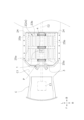
- FIG. 1 illustrates a vehicle undercarriage according to one embodiment of the present disclosure.
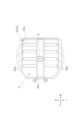
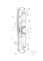
- FIG. 2 is a top view of a battery pack according to one embodiment of the present disclosure. 1 is a cross-sectional view of a mounting structure for a battery pack according to an embodiment of the present disclosure.
- FIG. 4 is an enlarged view of part A in FIG. 3 .
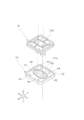
- FIG. 2 is a perspective view showing a top surface structure of a first member and a second member according to an embodiment of the present disclosure.
- FIG. 2 is a perspective view showing the underside structure of a first member and a second member according to an embodiment of the present disclosure.
- FIG. 2 is a perspective view illustrating a first reinforcing member and a second reinforcing member according to one embodiment of the present disclosure.
- the right side in the direction of travel of vehicle C will be designated as R, the left side as L, the front side as F, the rear side as B, the upper side as U, and the lower side as D.
- the battery pack mounting structure 1 of the present disclosure is a structure of a battery pack P that is arranged on the underside D of a floor C1 of a vehicle C.
- the vehicle C of the present disclosure is a plug-in hybrid electric vehicle (PHEV) that can be externally charged or externally powered.
- the vehicle C has an exhaust pipe E2 through which exhaust from an internal combustion engine E1 passes.
- the battery pack P is composed of secondary batteries such as lithium-ion batteries, and a battery module made up of multiple battery cells is arranged inside.
- the battery pack mounting structure 1 includes a case 2, a lower through hole (see Figure 1, an example of a first through hole) 4, an upper through hole (see Figure 2, an example of a second through hole) 6, a first member (see Figures 3 and 4) 8, a second member (see Figures 3 and 4) 10, a bolt 12, a plurality of first reinforcing members 14, and a plurality of second reinforcing members 16.
- the case 2 is a member for sealing the battery. As shown in FIG. 3, the case 2 has a housing member (an example of a lower member) 2a and a cover member (an example of an upper member) 2b that closes the opening 2c of the housing member 2a.
- the housing member 2a includes left and right side portions 22, a bottom portion 23 that connects the left and right side portions 22 to each other, a plurality of left and right support members 25a that extend in the left-right direction (the same as the width direction of the vehicle C, or the vehicle width direction) and support the housing member 2a, and a plurality of front and rear support members 25b that extend in the front-rear direction and support the housing member 2a.
- a bracket 24 is fixed to each of the left and right side portions 22.
- the bracket 24 is fixed to a side member C2 of the vehicle C with a bolt.
- the housing member 2a is a sheet metal member formed by press-molding a plate-shaped metal.
- the storage member 2a has a tunnel portion 3 in which the cross section of the bottom 23 bulges in an arch shape toward the upper side U of the vehicle C. As shown in FIG. 1, the tunnel portion 3 extends in the front-to-rear direction of the vehicle C.
- the exhaust pipe E2 passes through the tunnel portion 3.
- the bottom 23 has an upper surface 23a and a lower surface 23b. The lower surface 23b of the bottom 23 is visible in FIG. 1. As shown in FIG. 3, the bottom 23 has a saddle-shaped cross section with the tunnel portion 3 formed approximately in the center in the left-right direction.
- the cover member 2b has an upper surface 26a, a lower surface 26b, a protrusion 26c, and multiple ribs 26d.
- the multiple ribs 26d extend in the left-right direction, and the upper surface 26a is recessed toward the upper side U or the lower side D, thereby reinforcing the cover member 2b.
- the protrusion 26c is a portion where the upper surface 26a of the cover member 2b bulges upward to match the shape of the tunnel section 3.
- the cover member 2b of this embodiment is a sheet metal member formed by press molding a plate-shaped metal.
- the lower through hole 4 is provided in the storage member 2a of the case 2.
- the lower through hole 4 penetrates from the upper surface 23a to the lower surface 23b of the storage member 2a.
- the lower through hole 4 is provided at approximately the center in the left-right and front-rear directions.
- the lower through hole 4 has an elliptical shape that is long in the left-right direction of the battery pack P.
- the lower through hole 4 is provided in the tunnel portion 3 and penetrates from the upper surface 23a to the lower surface 23b of the tunnel portion 3.
- the upper through hole 6 is provided in the cover member 2b of the case 2.
- the lower through hole 4 penetrates from the lower surface 23b to the upper surface 23a of the housing member 2a.
- the upper through hole 6 is provided at the same position as the lower through hole 4 in the front-rear and left-right directions of the vehicle.
- the upper through hole 6 is provided at approximately the center of the battery pack P in the left-right and front-rear directions, similar to the lower through hole 4.
- the upper through hole 6 has an oval shape that is long in the left-right direction.
- the upper through hole 6 penetrates from the upper surface 26a to the lower surface 26b of the protrusion 26c of the cover member 2b.
- the first member 8 is positioned approximately in the center of the battery pack P in the left-right and front-rear directions, in line with the position of the lower through-hole 4. In this embodiment, the first member 8 is positioned on the lower surface 23b side of the tunnel portion 3 of the housing member 2a.
- the first member 8 is a member having a tubular member 30 that is inserted into the lower through-hole 4 and the upper through-hole 6. As shown in FIG. 5, the tubular member 30 and the first member 8 have a flange 31, a first seal portion 32, a third seal portion 33, an O-ring 34, and a plurality of bolt through-holes 35.
- the first member 8 is a metal member or a resin member.
- the tubular member 30 is a member having a length that extends from the lower surface 23b of the housing member 2a beyond the upper surface 26a of the cover member 2b.
- the tubular members 30 are cylindrical members arranged in two in the left-right direction.
- the battery pack P is fixed at the center by two bolts 12 arranged in the left-right direction.
- the flange 31 is a member to which the tubular members 30 are connected and has an upper surface 31a larger than the lower through-hole 4. The flange 31 contacts the lower surface 23b of the housing member 2a via the third seal portion 33, and supports the lower surface 23b when the bolts 12 are tightened.
- the first seal portion 32 is disposed around the tubular member 30.
- the first seal portion 32 is formed by attaching a seal member made of rubber or resin to a groove formed in the flange 31.
- the first seal portion 32 is formed along the shape of the lower through-hole 4.
- the first seal portion 32 seals between the periphery of the lower through-hole (see FIG. 4) 4 in the lower surface 23b of the accommodating member 2a and the upper surface 31a of the flange 31. This prevents water from entering the inside of the battery pack P through the lower through-hole 4.
- the third seal portion 33 is formed around the upper surface 31a of the flange 31.
- the third seal portion 33 is a dust seal made of rubber or resin. As shown in FIG. 4, the third seal portion 33 seals between the upper surface 31a of the flange 31 and the lower surface 23b of the housing member 2a, preventing dust from entering around the first seal portion 32.
- a plurality of bolt through holes 35 are arranged around the flange 31.
- the flange 31 is substantially rectangular, and the bolt through holes 35 are arranged at the four corners of the flange 31.
- a weld bolt (not shown) fixed to the lower surface 23b of the housing member 2a is inserted into the bolt through holes 35.
- a nut 36 is connected to the weld bolt and tightens the flange 31.
- the second member 10 is positioned approximately in the center of the battery pack P in the front-rear and left-right directions, in line with the position of the upper through-hole 6. In this embodiment, the second member 10 is positioned on the upper surface 26a side of the protrusion 26c of the cover member 2b.
- the second member 10 is a member having a through hole 40 (an example of a third through hole) through which the tubular member 30 is inserted. As shown in FIG. 6, the second member 10 has the through hole 40, a flange 41, a second seal portion 42, a fourth seal portion 43, and a plurality of bolt through holes 44.
- the second member 10 is a metal member or a resin member.
- the through holes 40 penetrate from the upper surface 41a to the lower surface 41b of the flange 41.
- the through holes 40 are formed according to the number of tubular members 30. In this embodiment, two through holes 40 are formed side by side in the left-right direction.
- the through holes 40 have a diameter slightly larger than the diameter of the tubular members 30.
- the through holes 40 are the inner peripheral surface of a tubular member extending from the upper surface 41a of the flange 41. As shown in FIG. 4, the O-ring 34 comes into contact with this inner peripheral surface, thereby sealing the outer peripheral surface of the tubular member 30 and the inner peripheral surface of the through holes 40. This prevents water from entering the inside of the battery pack P from the outer periphery of the tubular member 30.
- the second seal portion 42 is disposed around the through hole 40.
- the second seal portion 42 is formed by attaching a seal member made of rubber or resin to a groove formed in the flange 41.
- the second seal portion 42 is formed along the shape of the upper through hole 6.
- the second seal portion 42 seals between the periphery of the upper through hole 6 on the upper surface 26a of the cover member 2b and the lower surface 41b of the flange 41.
- the second seal portion 42 together with the O-ring 34, seals between the tubular member 30 and the upper through hole 6.
- water is prevented from entering the inside of the battery pack P through the upper through hole 6.
- the fourth seal portion 43 is formed around the lower surface 41b of the flange 41.
- the fourth seal portion 43 is a dust seal made of rubber or resin.
- the fourth seal portion 43 seals between the upper surface 41a of the flange 41 and the upper surface 26a of the cover member 2b, preventing dust from entering around the second seal portion 42.
- a number of bolt through holes 44 are arranged around the flange 41.
- the flange 41 is substantially rectangular, and the bolt through holes 44 are arranged at the four corners of the flange 41.
- a weld bolt (not shown) fixed to the upper surface 26a of the cover member 2b is inserted into the bolt through holes 44.
- a nut 45 is connected to the weld bolt and tightens the flange 41.
- the bolt 12 passes through the tubular member 30 and is fastened to a body member C3 of the vehicle C.
- the body member C3 is a structural member that is disposed between a pair of side members C2 and extends in the left-right direction.
- the body member C3 is, for example, a cross member.
- the first reinforcing member 14 is a member that extends along the shape of the lower surface 23b of the tunnel portion 3. As shown in FIG. 1, in this embodiment, three first reinforcing members 14 are arranged in a line in the front-rear direction. The lower through hole 4 and the first member 8 are arranged in a position shifted in the front-rear direction from the first reinforcing member 14 when viewed from the lower side D. As shown in FIG. 7, the first reinforcing member 14 has a rib 14a, a through hole 14b, a pair of left and right flanges (one example of both ends) 14c extending in the left-right direction, and a flange 14d extending along the tunnel portion 3.
- the rib 14a is provided so as to protrude toward the lower side D of the tunnel portion 3.
- the through hole 14b penetrates the pair of left and right flanges 14c. In this embodiment, a total of four through holes 14b are arranged, two on each side.
- the first reinforcing member 14 is a sheet metal member formed by press-molding a plate-shaped metal member.
- the first member 8 is disposed in the tunnel section 3.
- the lower end 12a of the bolt 12 that passes through the tubular member 30 of the first member 8 is positioned above the lower end 14e of the rib 14a of the first reinforcing member 14. This makes it difficult for heat generated from the exhaust pipe E2 to reach the first member 8.
- the flange 14c of the first reinforcing member 14 is welded to the lower surface 23b of the housing member 2a.
- the flange 14d of the first reinforcing member 14 is welded to the lower surface 23b of the tunnel section 3.
- a weld bolt is inserted into the through hole 14b of the first reinforcing member 14.
- the second reinforcing member 16 extends in the left-right direction of the vehicle C and is fixed to the lower surface 23b of the housing member 2a.
- the second reinforcing member 16 is arranged to be stacked on top of the first reinforcing member 14 in the up-down direction.
- the second reinforcing member 16 is a sheet metal member with a U-shaped cross section with an opening facing downward.
- the second reinforcing member 16 has a rib 16a, a through hole 16b, and a flange 16c.
- the rib 16a is provided in the center of the second reinforcing member 16 and is a portion that protrudes toward the lower side D.
- the through hole 14b is provided at the left and right ends of the second reinforcing member 16 and penetrates the second reinforcing member 16.
- a total of four through holes 16b are arranged, two at each of the left and right ends.
- the flange 16c is provided around the second reinforcing member 16.
- the second reinforcing member 16 is fixed to the housing member 2a by inserting a weld bolt welded to the housing member 2a into the through hole 16b and tightening the weld bolt with a nut.
- the weight of the battery is placed near the center of the housing member 2a of the battery pack P. For this reason, stress tends to concentrate near the center of the battery pack P. In particular, if the battery pack P has tunnel portions 3 in the left-right direction, stress concentration is even more likely to occur.
- the battery pack mounting structure 1 allows the bolt 12 to penetrate from the bottom surface 23b to the top surface 26a of the battery pack P. By fastening the bolt 12 to the vehicle body member C3, approximately the center of the battery pack P is supported by the vehicle body member C3. This allows the battery pack mounting structure 1 to reduce stress concentration near the center of the battery pack P. Furthermore, with this battery pack mounting structure 1, the worker installing the battery pack P can easily access the bolt 12 from the underside D of the battery pack P. This makes the battery pack mounting structure 1 easy to work with.
- the first member 8 and the second member 10 can be used to seal the periphery of the lower through-hole 4 and the upper through-hole 6 of the battery pack P. This allows the battery pack P to be kept sealed.
- the present disclosure provides a mounting structure 1 for a battery pack P that allows the bolt 12 to be fastened to a vehicle body member C3 by penetrating the case 2 from the lower member of the case 2.
- a battery pack P having a tunnel portion 3 is used, but the present disclosure is not limited to this.
- the battery pack P may be a battery pack that does not have a tunnel portion 3.
- the first member 8 and the second member 10 are disposed approximately in the center of the battery pack P in the left-right and front-rear directions, and the bolt 12 is fixed thereto.
- the present disclosure is not limited to this.
- the position of the bolt 12 may be appropriately determined according to the load applied to the battery pack P.
Landscapes
- Engineering & Computer Science (AREA)
- Chemical & Material Sciences (AREA)
- Combustion & Propulsion (AREA)
- Transportation (AREA)
- Mechanical Engineering (AREA)
- Battery Mounting, Suspending (AREA)
- Arrangement Or Mounting Of Propulsion Units For Vehicles (AREA)
Priority Applications (2)
| Application Number | Priority Date | Filing Date | Title |
|---|---|---|---|
| PCT/JP2023/009969 WO2024189807A1 (ja) | 2023-03-15 | 2023-03-15 | バッテリパックの取り付け構造 |
| JP2025506340A JP7845571B2 (ja) | 2023-03-15 | 2023-03-15 | バッテリパックの取り付け構造 |
Applications Claiming Priority (1)
| Application Number | Priority Date | Filing Date | Title |
|---|---|---|---|
| PCT/JP2023/009969 WO2024189807A1 (ja) | 2023-03-15 | 2023-03-15 | バッテリパックの取り付け構造 |
Publications (1)
| Publication Number | Publication Date |
|---|---|
| WO2024189807A1 true WO2024189807A1 (ja) | 2024-09-19 |
Family
ID=92754700
Family Applications (1)
| Application Number | Title | Priority Date | Filing Date |
|---|---|---|---|
| PCT/JP2023/009969 Ceased WO2024189807A1 (ja) | 2023-03-15 | 2023-03-15 | バッテリパックの取り付け構造 |
Country Status (2)
| Country | Link |
|---|---|
| JP (1) | JP7845571B2 (https=) |
| WO (1) | WO2024189807A1 (https=) |
Citations (3)
| Publication number | Priority date | Publication date | Assignee | Title |
|---|---|---|---|---|
| JP5734453B2 (ja) * | 2011-11-14 | 2015-06-17 | 本田技研工業株式会社 | バッテリの車載構造 |
| JP2018193003A (ja) * | 2017-05-19 | 2018-12-06 | 本田技研工業株式会社 | 車体下部構造 |
| WO2022163054A1 (ja) * | 2021-01-26 | 2022-08-04 | 帝人株式会社 | 車両構造体 |
-
2023
- 2023-03-15 WO PCT/JP2023/009969 patent/WO2024189807A1/ja not_active Ceased
- 2023-03-15 JP JP2025506340A patent/JP7845571B2/ja active Active
Patent Citations (3)
| Publication number | Priority date | Publication date | Assignee | Title |
|---|---|---|---|---|
| JP5734453B2 (ja) * | 2011-11-14 | 2015-06-17 | 本田技研工業株式会社 | バッテリの車載構造 |
| JP2018193003A (ja) * | 2017-05-19 | 2018-12-06 | 本田技研工業株式会社 | 車体下部構造 |
| WO2022163054A1 (ja) * | 2021-01-26 | 2022-08-04 | 帝人株式会社 | 車両構造体 |
Also Published As
| Publication number | Publication date |
|---|---|
| JPWO2024189807A1 (https=) | 2024-09-19 |
| JP7845571B2 (ja) | 2026-04-14 |
Similar Documents
| Publication | Publication Date | Title |
|---|---|---|
| JP6614012B2 (ja) | 車両のバッテリ搭載構造 | |
| US10569633B2 (en) | Battery mounting structure for vehicle | |
| JP6020958B2 (ja) | 電池パックトレー | |
| CN107379949B (zh) | 车辆的蓄电池搭载构造 | |
| JP6414021B2 (ja) | 燃料電池の搭載構造 | |
| JP4386131B2 (ja) | 電気自動車 | |
| JP5098544B2 (ja) | バッテリユニット | |
| JP4306783B2 (ja) | 電気自動車のバッテリユニット取付構造 | |
| JP3828000B2 (ja) | 金属製電装ケースの防振構造 | |
| JP6115659B2 (ja) | 電池容器 | |
| US20180236863A1 (en) | Vehicle body bottom structure | |
| KR20180055485A (ko) | 차체의 배터리 지지구조 | |
| US20130192914A1 (en) | Battery container | |
| KR102407864B1 (ko) | 전기 및 하이브리드 차량용 배터리 케이스 | |
| JP7259667B2 (ja) | 燃料電池スタックの車両搭載構造及び車両搭載方法 | |
| KR20190084523A (ko) | 측방 차체 보강구조 | |
| JP2011124101A (ja) | バッテリーケース | |
| JP5109559B2 (ja) | バッテリユニット | |
| WO2020162028A1 (ja) | 電池パックの取付構造 | |
| JP2019114469A (ja) | 燃料電池車両 | |
| JP4754321B2 (ja) | 燃料電池自動車 | |
| KR20190080578A (ko) | 전기자동차용 배터리팩의 마운팅 유닛 | |
| KR102586066B1 (ko) | 전기자동차용 배터리 케이스 | |
| CN111710891B (zh) | 燃料电池车辆 | |
| JP7845571B2 (ja) | バッテリパックの取り付け構造 |
Legal Events
| Date | Code | Title | Description |
|---|---|---|---|
| 121 | Ep: the epo has been informed by wipo that ep was designated in this application |
Ref document number: 23927428 Country of ref document: EP Kind code of ref document: A1 |
|
| WWE | Wipo information: entry into national phase |
Ref document number: 2025506340 Country of ref document: JP |
|
| NENP | Non-entry into the national phase |
Ref country code: DE |
|
| 122 | Ep: pct application non-entry in european phase |
Ref document number: 23927428 Country of ref document: EP Kind code of ref document: A1 |