WO2024189732A1 - 香味スティック及び非燃焼型香味吸引システム - Google Patents
香味スティック及び非燃焼型香味吸引システム Download PDFInfo
- Publication number
- WO2024189732A1 WO2024189732A1 PCT/JP2023/009584 JP2023009584W WO2024189732A1 WO 2024189732 A1 WO2024189732 A1 WO 2024189732A1 JP 2023009584 W JP2023009584 W JP 2023009584W WO 2024189732 A1 WO2024189732 A1 WO 2024189732A1
- Authority
- WO
- WIPO (PCT)
- Prior art keywords
- flavor
- stick
- ventilation
- tobacco
- air
- Prior art date
- Legal status (The legal status is an assumption and is not a legal conclusion. Google has not performed a legal analysis and makes no representation as to the accuracy of the status listed.)
- Ceased
Links
Images





Classifications
-
- A—HUMAN NECESSITIES
- A24—TOBACCO; CIGARS; CIGARETTES; SIMULATED SMOKING DEVICES; SMOKERS' REQUISITES
- A24D—CIGARS; CIGARETTES; TOBACCO SMOKE FILTERS; MOUTHPIECES OF CIGARS OR CIGARETTES; MANUFACTURE OF TOBACCO SMOKE FILTERS OR MOUTHPIECES
- A24D1/00—Cigars; Cigarettes
- A24D1/20—Cigarettes specially adapted for simulated smoking devices
-
- A—HUMAN NECESSITIES
- A24—TOBACCO; CIGARS; CIGARETTES; SIMULATED SMOKING DEVICES; SMOKERS' REQUISITES
- A24F—SMOKERS' REQUISITES; MATCH BOXES; SIMULATED SMOKING DEVICES
- A24F40/00—Electrically operated smoking devices; Component parts thereof; Manufacture thereof; Maintenance or testing thereof; Charging means specially adapted therefor
- A24F40/40—Constructional details, e.g. connection of cartridges and battery parts
- A24F40/46—Shape or structure of electric heating means
- A24F40/465—Shape or structure of electric heating means specially adapted for induction heating
Definitions
- Patent Document 1 proposes that an aerosol-generating article includes an aerosol-forming base surrounded in the radial direction by a sheet of a thermally conductive material such as metal foil, thereby reducing the risk of the aerosol-forming base being ignited by a user applying a flame to the aerosol-generating article.
- metal foil is used as a cigarette paper, there are problems such as the inability to control the weight using microwaves, low flexibility that makes it easy to wrinkle or crush, and high cost, which creates manufacturing constraints, making it difficult to manufacture easily, or putting a high burden on the environment.
- Patent Document 2 proposes a heated aerosol generating article for use with an aerosol generating device, which defines a first airflow path through which air drawn in through the mouth end passes through the aerosol-forming substrate, and a second airflow path through which the drawn in air does not pass through the aerosol-forming substrate.
- the heated aerosol generating article is not engaged with the aerosol generating device and a user inhales from the mouth end, the air passes through the second airflow path and does not pass through the aerosol-forming substrate. Therefore, even if a user attempts to ignite the article by bringing a flame close to the distal end of the rod, as with a conventional cigarette, air does not flow through the aerosol-forming substrate, and ignition of the aerosol-forming substrate is suppressed.
- the technology disclosed herein has been made in consideration of the above-mentioned circumstances, and its purpose is to provide a technology that can prevent ignition of a flavor stick that is heated by a non-combustion flavor inhalation device and used for smoking, even if an attempt is made to light it, and that allows for proper smoking.
- the flavor stick of the present disclosure comprises: A flavor stick that is inserted into and removed from a storage section of a non-burning flavor inhalation device and is heated while being stored in the storage section, a flavor fill comprising a flavor source and an aerosol-forming substrate; A cylindrical member at least a portion of which is filled with the flavor filling, The cylindrical member is One end is the tip end and the other end is the mouth end, A ventilation portion is provided on a peripheral wall of the cylindrical member to allow air to flow from the outside to the internal space, The tip, the ventilation section, and the suction port end are communicated with each other so that air flowing in from the tip and the ventilation section is sucked out from the suction port end when suction is performed from the suction port end side, The ventilation portion is a first ventilation section in which the inflow of the air is restricted by an inner wall of the storage section when the tip side of the flavor stick is stored in the storage section in a specified state; and a second ventilation section which is located closer to the
- the ventilation portion may be an opening provided in the peripheral wall of the tubular member, or a portion of the peripheral wall formed from a breathable material.
- the flavor stick according to any one of the above aspects 1 to 3 includes a flavor rod portion filled with the flavor filling, and a mouthpiece portion disposed closer to the mouth end than the flavor rod portion,
- the first ventilation portion may be provided in at least one of the flavor rod portion and the mouthpiece portion.
- the first ventilation portion may be provided in the flavor rod portion.
- the flavor stick according to any one of Aspects 1 to 5 above may have an airflow resistance from the tip to the mouth end of 45 mmWG or less when not contained in the containing section, and the airflow resistance may be measured according to the ISO 9512 method.
- the flavor stick of Aspect 6 above may have an airflow resistance from the tip to the mouth end of 10 mmWG or more when not contained in the container.
- the non-combustion type flavor inhalation system of the present disclosure includes: A flavor stick according to any one of the above aspects 1 to 7, and a non-combustion type flavor inhalation device for heating the flavor stick,
- the non-burning flavor inhalation device comprises: a storage section capable of storing the flavor stick and having an inner wall that limits ventilation of the ventilation section when the flavor stick is stored therein; A heating unit that heats the flavor stick contained in the container; Equipped with.
- the heating unit may have an electric heater that generates heat when supplied with power, an induction coil that heats a heating element arranged within the flavor stick or around the flavor stick by electromagnetic induction, or a microwave generator that applies microwaves to the flavor stick to heat it.
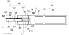
- FIG. 1A is a schematic diagram of a non-combustion type flavor inhalation system according to an embodiment.
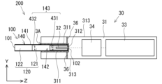
- FIG. 1B is a schematic diagram of a non-combustion type flavor inhalation system having a different configuration from that of FIG. 1A, in which the heater is an internal heating type.
- FIG. 2 is a perspective view of a tobacco stick according to the embodiment.
- FIG. 3 is a diagram illustrating the internal structure of the tobacco stick according to the embodiment.
- FIG. 4 is a schematic diagram showing the ventilation relationship of a tobacco stick.
- FIG. 5 is a diagram showing the specifications of the wrapping paper.
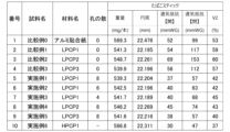
- FIG. 6 is a diagram showing the airflow resistance and the like of tobacco sticks in Examples and Comparative Examples.
- FIG. 7 is a graph showing the relationship between the volume ratio of the tip ventilation volume of air flowing in from the tip to the intake volume of air inhaled from the mouth end of a tobacco stick measured by the ISO 9512 method when the tobacco stick is not contained in the accommodation portion of an inhalation device, and the amount of carbon monoxide contained in the air inhaled from the mouth end when 3 puffs per tobacco stick are ignited and smoked under CIR conditions, in Examples and Comparative Examples.
- FIG. 8 is a graph showing the relationship between the airflow resistance of a tobacco stick, measured by the ISO 9512 method when the tobacco stick is not contained in the container of an inhalation device, and the amount of carbon monoxide contained in the air inhaled from the mouth end when 3 puffs per tobacco stick are ignited and smoked under CIR conditions, in Examples and Comparative Examples.
- FIG. 8 is a graph showing the relationship between the airflow resistance of a tobacco stick, measured by the ISO 9512 method when the tobacco stick is not contained in the container of an inhalation device, and the amount of carbon monoxide contained in the air inhaled from the mouth end when 3 puffs per tobacco stick are ignited and smoked under CIR conditions, in Examples and Comparative Examples.
- FIG. 9 is a table showing the tip airflow (Vt) of the tobacco stick, the volumetric ratio of the air flowing in from the first opening (V1) and the second opening (V2), and the airflow resistance when measured by the ISO 9512 method when the tobacco stick is not contained in the storage portion of the inhalation device, and the amount of carbon monoxide contained in the air inhaled from the mouth end when igniting and smoking 3 puffs per tobacco stick under CIR conditions in the examples and comparative examples.
- FIG. 10 is a diagram showing a modified example of the non-combustion type flavor inhalation device according to the first modified example.
- FIG. 11 is a diagram showing an inflow path of air flowing into a tobacco stick when the tobacco stick is stored in the non-combustion flavor inhalation device according to the first modified example.
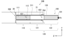
- FIG. 12 is a diagram showing a modified example of a non-combustion type flavor inhalation device according to the second modified example.
- a flavor stick (hereinafter also referred to as a "tobacco stick") containing a tobacco filler as a flavor source will be described as an example of a flavor stick, but the flavor stick may not contain a tobacco filler and may contain other flavor components.
- FIG. 1A is a schematic diagram of a non-combustion flavor inhalation system 200 according to an embodiment
- FIG. 1B is a schematic diagram of a non-combustion flavor inhalation system 200 having a different configuration from FIG. 1A in that the heater is an internal heating type
- FIG. 2 is a perspective view of a tobacco stick 100 according to an embodiment
- FIG. 3 is a diagram for explaining the internal structure of the tobacco stick 100 according to an embodiment.
- the left-right direction is shown as the X direction
- the up-down direction is shown as the Y direction
- the depth direction is shown as the Z direction. This also applies to the subsequent figures.
- the non-burning flavor inhalation system 200 includes a tobacco stick 100 and a non-burning flavor inhalation device 30 that heats a portion of the tobacco stick 100 while being housed therein.
- the tobacco stick 100 is housed in a housing portion 35 through an insertion port 3A of the non-burning flavor inhalation device 30 so as to be freely insertable and removable.
- the tobacco stick 100 of this embodiment includes a tobacco filler (flavor filler) containing a flavor source and an aerosol generating base material, and a tubular member 140 at least partially filled with the tobacco filler.
- the portion of the tubular member 140 filled with the tobacco filler is also referred to as a tobacco rod portion (flavor rod portion) 110, and the portion of the tobacco rod portion 110 on the mouth end 101 side is also referred to as a mouthpiece portion 120. That is, the tobacco stick 100 includes a tobacco rod portion 110 and a mouthpiece portion 120.
- the tobacco stick 100 When the non-combustion flavor inhalation device 30 is used by a user, the tobacco stick 100 is inserted into the storage section 35, and in this state, the tobacco rod section 110 of the tobacco stick 100 is heated to generate an aerosol containing tobacco components, which is then inhaled by the user.
- the cylindrical member 140 has a tip 102 at one end and a suction end 101 at the other end, and a vent 143 is provided on the peripheral wall 141 that forms the cylindrical member 140 to allow air to flow from the outside into the inner space 142.
- the tip 102, vent 143, and suction end 101 are connected to the cylindrical member 140 so that when suction is applied from the suction end 101 side, air that flows in from the tip 102 and vent 143 is sucked out from the suction end 101.
- the ventilation section 143 has a first ventilation section 431 arranged on the tip 102 side of the tobacco stick 100, and a second ventilation section 432 arranged on the mouth end 101 side. If a user mistakes the tobacco stick 100 for a conventional cigarette and attempts to smoke by lighting the tip 102 without inserting it into the non-combustion flavor inhalation device 30, air will be drawn into the tobacco stick 100 not only from the tip 102 but also from the ventilation section 143. As a result, the tobacco stick 100 has less air flowing in from the tip 102 than a conventional cigarette, and the embers do not grow, suppressing accidental ignition.
- the tobacco stick 100 when used correctly, the tobacco stick 100 is inserted by the user with the tip 102 side into the storage section 35 of the non-combustion flavor inhalation device 30. That is, a part of the tip 102 side of the tobacco stick 100 is stored in the storage section 35 of the non-combustion flavor inhalation device 30.
- the state in which the tobacco stick 100 is properly stored in the storage section 35 is also referred to as the specified state or specified storage state.
- the specified state may also mean a state in which the tip 102 of the tobacco stick 100 is inserted until it hits the wall of the storage section 35 (the distal wall 312 described below), or a state in which the tobacco stick 100 of this embodiment designed for the non-combustion flavor inhalation device 30 is inserted.
- the first ventilation portion 431 of the ventilation portion 143 is disposed so as to be located inside the storage portion 35 in a specified storage state, and the second ventilation portion 432 is disposed so as to be located outside the storage portion 35 in a specified state. For this reason, when the tobacco stick 100 is stored in the non-combustion type flavor inhalation device 30 in a specified state, the inflow of air into the first ventilation portion 431 of the ventilation portion 143 is restricted by the inner wall of the storage portion 35, and the inflow of air into the second ventilation portion 432 is not restricted by the inner wall of the storage portion 35.
- the non-combustion flavor inhalation system 200 of this embodiment is configured to suppress accidental ignition when the tobacco stick 100 is not housed in the non-combustion flavor inhalation device 30, and to allow appropriate smoking in a specified housing state.
- the tobacco stick 100 has a substantially cylindrical rod shape.
- the tobacco stick 100 includes a tobacco rod portion 110, a mouthpiece portion 120, and tipping paper 130 that connects them together.
- the mouthpiece portion 120 is connected coaxially to the tobacco rod portion 110 by being wrapped around the tobacco rod portion 110 by the tipping paper 130.
- the tobacco rod portion 110 is disposed on the tip 102 side of the tobacco stick 100.
- the tobacco rod portion 110 is not limited to being disposed at the very tip of the tobacco stick 100.
- a member similar to a filter segment, which will be described later, may be disposed on the tip 102 side of the tobacco rod portion 110.
- the tobacco stick 100 shown in Figures 2 and 3 has a substantially constant diameter over its entire length in the longitudinal direction (hereinafter also referred to as the axial direction or Z direction) from the mouth end 101 along the tip 102.
- the material of the tipping paper 130 is not particularly limited, and may be paper made of general plant fiber (pulp), a sheet using polymer-based chemical fiber (polypropylene, polyethylene, nylon, etc.), a polymer-based sheet, metal foil, or a composite material combining these.
- the tipping paper 130 may be made of a composite material in which a polymer-based sheet is bonded to a paper base material.
- the tipping paper 130 here refers to a sheet-like material that connects multiple segments in the tobacco stick 100, for example, connecting the tobacco rod portion 110 and the mouthpiece portion 120.
- the basis weight of the tipping paper 130 is not particularly limited, but is usually 32 gsm or more and 60 gsm or less, preferably 33 gsm or more and 50 gsm or less, and more preferably 34 gsm or more and 40 gsm or less.
- the air permeability of the tipping paper 130 is not particularly limited, but is usually 0 Coresta units or more and 30,000 Coresta units or less, and preferably more than 0 Coresta units and 10,000 Coresta units or less.
- the air permeability is a value measured in accordance with ISO 2965:2009, and is expressed as the flow rate (cm 3 ) of gas passing through an area of 1 cm 2 per minute when the differential pressure between both sides of the paper is 1 kPa.
- 1 Coresta unit (1 Coresta unit, 1 CU) is cm 3 /(min ⁇ cm 2 ) under 1 kPa.
- the chip paper 130 may contain fillers other than the above-mentioned pulp, such as metal carbonates such as calcium carbonate and magnesium carbonate, metal oxides such as titanium oxide, titanium dioxide and aluminum oxide, metal sulfates such as barium sulfate and calcium sulfate, metal sulfides such as zinc sulfide, quartz, kaolin, talc, diatomaceous earth, gypsum, etc., and it is particularly preferable that the chip paper 130 contains calcium carbonate from the viewpoint of improving whiteness and opacity and increasing the heating rate. Furthermore, these fillers may be used alone or in combination of two or more types.
- the chip paper 130 may have a water resistance improver to improve water resistance.
- Water resistance improvers include wet strength agents (WS agents) and sizing agents.
- wet strength agents include urea formaldehyde resin, melamine formaldehyde resin, polyamide epichlorohydrin (PAE), etc.
- sizing agents include rosin soap, alkyl ketene dimer (AKD), alkenyl succinic anhydride (ASA), and highly saponified polyvinyl alcohol with a saponification degree of 90% or more.
- a coating agent may be added to at least one of the two surfaces of the tipping paper 130, the front and back surfaces.
- the coating agent There are no particular limitations on the coating agent, but a coating agent that can form a film on the surface of the paper and reduce the permeability to liquids is preferred.
- the method for manufacturing the tip paper 130 is not particularly limited, and general methods can be applied.
- a method can be used in which the texture is adjusted and made uniform during the papermaking process using a Fourdrinier papermaking machine, a cylinder papermaking machine, a combined cylinder and short-circuit papermaking machine, etc. using pulp.
- a wet strength agent can be added to impart water resistance, or a sizing agent can be added to adjust the print quality.
- the configuration of the tobacco rod portion 110 is not particularly limited and may be of a general form.
- a tobacco filler 111 wrapped in cigarette paper 112 may be used.
- the axial length of the tobacco rod portion 110 can be changed as appropriate to suit the size of the product, but is, for example, 5 mm or more, preferably 10 mm or more, more preferably 12 mm or more, and even more preferably 14 mm or more, and is usually 70 mm or less, preferably 50 mm or less, more preferably 30 mm or less, and even more preferably 25 mm or less.
- the tobacco filler 111 is configured to include tobacco shreds.
- the material of the tobacco shreds contained in the tobacco filler 111 is not particularly limited, and known materials such as lamina and ribs can be used.
- the tobacco filler 111 may be a shredded product obtained by crushing dried tobacco leaves to an average particle size of 20 ⁇ m or more and 200 ⁇ m or less to obtain tobacco shreds, homogenizing the shredded product, and processing the shredded product into a sheet (hereinafter, simply referred to as a homogenized sheet).
- the tobacco filler 111 may be a so-called strand type product in which a homogenized sheet having a length approximately equal to the longitudinal direction of the tobacco rod is shredded approximately horizontally to the longitudinal direction of the tobacco rod and filled into the tobacco rod.
- the width of the tobacco shreds is preferably 0.5 mm or more and 2.0 mm or less when filling the tobacco rod portion 110.
- the content of the dried tobacco leaves contained in the tobacco rod portion 110 is not particularly limited, but may be 200 mg/rod portion or more and 800 mg/rod portion or less, and preferably 250 mg/rod portion or more and 600 mg/rod portion or less. This range is particularly suitable for the tobacco rod portion 110 having a circumference of 22 mm and a length of 20 mm.
- Various types of tobacco can be used for the tobacco leaves used in the preparation of the tobacco shreds and homogenized sheets. Examples include flue-cured, burley, orient, native, other Nicotiana tabacum varieties, Nicotiana rustica varieties, and mixtures of these. The above varieties can be appropriately blended to achieve the desired flavor. Details of the tobacco varieties are disclosed in "Encyclopedia of Tobacco, Tobacco Research Center, March 31, 2009." There are several conventional methods for producing the homogenized sheets, that is, methods for grinding tobacco leaves and processing them into homogenized sheets. The first method is to produce a paper-making sheet using a papermaking process.
- the second method is to mix a suitable solvent such as water with the ground tobacco leaves to homogenize them, and then cast the homogenized mixture thinly on a metal plate or metal plate belt and dry it to produce a cast sheet.
- the third method is to mix a suitable solvent such as water with the ground tobacco leaves to homogenize them, and extrude the mixture into a sheet to produce a rolled sheet. Details of the types of homogenizing sheets are disclosed in "Encyclopedia of Tobacco, Tobacco Research Center, March 31, 2009."
- the moisture content of the tobacco filling 111 can be 10% by weight or more and 15% by weight or less, and is preferably 11% by weight or more and 13% by weight or less, based on the total amount of the tobacco filling 111. Such a moisture content suppresses the occurrence of rolling stains and improves the suitability of the tobacco rod portion 110 for rolling during production.
- dried tobacco leaves may be crushed to an average particle size of about 20 ⁇ m to 200 ⁇ m, homogenized, processed into a sheet, and then shredded to a width of 0.5 mm or more and 2.0 mm or less may be used.
- the tobacco filling 111 may contain an aerosol base material that generates aerosol smoke.
- the type of the aerosol base material is not particularly limited, and various extracts from natural products and/or their constituents can be selected depending on the application.
- aerosol base materials include glycerin, propylene glycol, triacetin, 1,3-butanediol, and mixtures thereof.
- the content of the aerosol base material in the tobacco filling 111 is not particularly limited, and from the viewpoint of generating sufficient aerosol and imparting a good flavor, it is usually 5% by weight or more, preferably 10% by weight or more, and usually 50% by weight or less, preferably 15% by weight or more and 25% by weight or less, based on the total amount of the tobacco filling.
- the tobacco filling 111 may contain a flavoring.
- the type of flavoring is not particularly limited, and from the viewpoint of imparting a good flavor, the following flavorings may be used: acetanisole, acetophenone, acetylpyrazine, 2-acetylthiazole, alfalfa extract, amyl alcohol, amyl butyrate, trans-anethole, star anise oil, apple juice, Peru balsam oil, beeswax absolute, benzaldehyde, benzoin resinoid, benzyl alcohol, benzyl benzoate, benzyl phenylacetate, benzyl propionate, 2,3-butanedione, 2-butanol, butyl butyrate, butyric acid, caramel, cardamom oil, carob absolute, ⁇ -Carotene, carrot juice, L-carvone, ⁇ -caryophyllene, cassia bark oil, cedarwood oil, cele
- the content of the flavoring in the tobacco filling 111 is not particularly limited, but from the viewpoint of imparting a good flavor, it is usually 10,000 ppm or more, preferably 20,000 ppm or more, more preferably 25,000 ppm or more, and usually 70,000 ppm or less, preferably 50,000 ppm or less, more preferably 40,000 ppm or less, and even more preferably 33,000 ppm or less.
- the cigarette paper 112 is a sheet material for wrapping the tobacco filler 111, and its configuration is not particularly limited, and a general one can be used.
- the base paper used for the cigarette paper 112 can be cellulose fiber paper, and more specifically, hemp or wood or a mixture thereof can be used.
- the basis weight of the base paper in the cigarette paper 112 is, for example, 10 gsm or more, and preferably 25 gsm or more. On the other hand, the basis weight is usually 65 gsm or less, preferably 50 gsm or less, and more preferably 45 gsm or less.
- the thickness of the cigarette paper 112 having the above characteristics is not particularly limited, and from the viewpoints of rigidity, breathability, and ease of adjustment during papermaking, it is usually 10 ⁇ m or more, preferably 20 ⁇ m or more, and more preferably 30 ⁇ m or more, and also usually 100 ⁇ m or less, preferably 75 ⁇ m or less, and more preferably 50 ⁇ m or less.
- the shape of the cigarette paper 112 for the tobacco rod portion 110 can be square or rectangular.
- the length of one side can be approximately 6 mm to 70 mm
- the length of the other side can be 15 mm to 28 mm
- the preferred length of the other side can be 22 mm to 24 mm, with the more preferred length being approximately 23 mm.
- the wrapping paper 112 may contain a filler.
- the amount of the filler may be from 0% to less than 60% by weight, and is preferably 45% by weight or less, based on the total weight of the wrapping paper 112.
- fillers that can be used include calcium carbonate, titanium dioxide, and kaolin, but it is preferable to use calcium carbonate from the viewpoint of enhancing flavor and whiteness.
- auxiliary agents other than the base paper and fillers may be added to the wrapping paper 112.
- a wrapping paper combustion improver may be added as an auxiliary agent, and examples of such wrapping paper combustion improvers include sodium citrate and potassium citrate.
- a paper strength enhancer may be added as an auxiliary agent, and examples of such auxiliary agents include polyacrylamide, cationic starch, oxidized starch, CMC, polyamide epichlorohydrin resin, polyvinyl alcohol, and the like.
- a very small amount of oxidized starch improves breathability (for example, JP 2017-218699 A).
- a coating agent may be added to at least one of the two surfaces of the wrapping paper 112, the front and back.
- a coating agent that can form a film on the surface of the paper and reduce liquid permeability is preferred.
- examples include alginic acid and its salts (e.g., sodium salts), polysaccharides such as arabic gum, guar gum, and pectin, cellulose derivatives such as ethyl cellulose, methyl cellulose, carboxymethyl cellulose, and nitrocellulose, starch and its derivatives (e.g., ether derivatives such as carboxymethyl starch, hydroxyalkyl starch, and cationic starch, and ester derivatives such as starch acetate, starch phosphate, and starch octenyl succinate).
- alginic acid and its salts e.g., sodium salts
- polysaccharides such as arabic gum, guar gum, and pectin
- cellulose derivatives such as ethyl
- the cigarette paper 112 of this embodiment is provided with a first ventilation section 431 that allows air to flow from the outside to the inside when the tobacco filler 111 is wrapped.
- the first ventilation section 431 is a through hole that penetrates from the outer surface to the inner surface of the cigarette paper 112 wrapped with the tobacco filler 111.
- the number and shape of the holes of the first ventilation section 431 provided in the cigarette paper 112 are not particularly limited.
- multiple first ventilation sections 431 are arranged at regular intervals in the circumferential direction of the tobacco rod section 110.
- multiple groups of first ventilation sections 431 arranged in the circumferential direction of the tobacco rod section 110 may be formed along the axial direction of the tobacco rod section 110.
- the first ventilation section 431 is not limited to a through hole, and may be formed by forming the cigarette paper 112 from a breathable member such as a nonwoven fabric or mesh (hereinafter also referred to as a breathable material) to allow air to flow from the outside to the inner space.
- a breathable member such as a nonwoven fabric or mesh (hereinafter also referred to as a breathable material) to allow air to flow from the outside to the inner space.
- the first ventilation section 431 may be configured by combining a through hole and a breathable material.
- the configuration of the mouthpiece portion 120 is not particularly limited and may be a general embodiment.
- the mouthpiece portion 120 includes two segments (divisions), for example, a cooling segment 121 and a filter segment 122.
- the cooling segment 121 is disposed so as to be sandwiched between the tobacco rod portion 110 and the filter segment 122 in a state of contact with them.
- a gap may be formed between the tobacco rod portion 110 and the cooling segment 121, and between the tobacco rod portion 110 and the filter segment 122.
- the mouthpiece portion 120 may also be formed from a single segment.
- the configuration of the cooling segment 121 is not particularly limited as long as it has the function of cooling the mainstream smoke of tobacco, and an example of the cooling segment 121 is a cardboard processed into a cylindrical shape.
- the inside of the cylinder is hollow, and the vapor containing the aerosol-generating base material and the tobacco flavor component is cooled by contacting with the air in the cavity.
- the cooling segment 121 may also be configured to be a hollow filter material such as breathable paper or cellulose acetate tow.
- cooling segment 121 may be a paper tube formed by processing a single sheet of paper or a sheet of paper bonded together into a cylindrical shape.
- through holes (second ventilation parts) 432 for introducing outside air are provided around the periphery of the paper tube.
- the number of second ventilation parts 432 in the cooling segment 121 is not particularly limited.
- a plurality of second ventilation parts 432 are arranged at regular intervals in the circumferential direction of the cooling segment 121.
- a plurality of groups of second ventilation parts 432 arranged in the circumferential direction of the cooling segment 121 may be formed along the axial direction of the cooling segment 121.
- the second ventilation parts 432 in the cooling segment 121, when the tobacco stick 100 is sucked, low-temperature air flows into the cooling segment 121 from the outside, and the temperature of the volatile components and air flowing in from the tobacco rod part 110 can be reduced.
- the vapor containing the aerosol-generating base material and the tobacco flavor component is cooled by the low-temperature air introduced into the cooling segment 121 through the second ventilation section 432, and condenses. This promotes the generation of aerosol and allows the size of the aerosol particles to be controlled.
- the cooling effect can be increased by applying a polymer coating such as polyvinyl alcohol or a polysaccharide coating such as pectin to the inner surface of the paper tube, utilizing the heat of dissolution associated with the heat absorption and phase change of the coating.
- a polymer coating such as polyvinyl alcohol or a polysaccharide coating such as pectin
- the airflow resistance of this cylindrical cooling segment is zero mmH2O .
- the total surface area of the cooling segment 121 is not particularly limited, and may be, for example, 300 mm2 /mm or more and 1000 mm2 /mm or less. This surface area is the surface area per mm of the length (mm) in the air passage direction of the cooling segment 121.
- the total surface area of the cooling segment 121 is preferably 400 mm2 /mm or more, more preferably 450 mm2 /mm or more, while it is preferably 600 mm2 /mm or less, and more preferably 550 mm2 /mm or less.
- the cooling segment 121 may be formed from a thin sheet of material that is wrinkled to form channels, and then pleated, gathered, and folded. The more folds or pleats within a given volume of the element, the greater the total surface area of the cooling segment 121.
- the thickness of the constituent material of the cooling segment 121 is not particularly limited and may be, for example, 5 ⁇ m or more and 500 ⁇ m or less, and 10 ⁇ m or more and 250 ⁇ m or less.
- the paper as a material for the cooling sheet member desirably has a basis weight of 30 to 100 g/m 2 and a thickness of 20 to 100 ⁇ m. From the viewpoint of reducing the removal of flavor source components and aerosol base components in the cooling segment, it is desirable for the paper as a material for the cooling sheet to have low air permeability, and the air permeability is preferably 10 Coresta or less.
- the cooling effect can be increased by utilizing the heat of dissolution associated with the heat absorption or phase change of the coating.
- the second ventilation section 432 in the cooling segment 121 is disposed at a position 4 mm or more away from the boundary between the cooling segment 121 and the filter segment 122. This not only improves the cooling capacity of the cooling segment 121, but also suppresses the retention of components generated by heating in the cooling segment 121, thereby improving the delivery amount of the components.
- the second ventilation section 432 provided in the cooling segment 121 is connected to the second ventilation section 432 provided in the tipping paper 130, and is formed to allow air to flow from the outside to the inside of the tobacco stick 100.
- the tipping paper 130 has an opening provided directly above the second ventilation section 432 provided in the cooling segment 121 (a position where they overlap in the radial direction).
- the second ventilation section 432 is not limited to a through hole, and may be formed of a highly breathable material such as nonwoven fabric or mesh, allowing air to flow from the outside into the inner space.
- the second ventilation section 432 may also be configured by combining a through hole and a breathable material.
- the axial length (air flow direction) of the cooling segment 121 is not particularly limited, but is usually 10 mm or more, preferably 15 mm or more, and usually 40 mm or less, preferably 35 mm or less, and more preferably 30 mm or less. It is particularly preferable that the axial length of the cooling segment 121 is 20 mm.
- the configuration of the filter segment 122 is not particularly limited as long as it has a function as a general filter, and for example, cellulose acetate tow processed into a cylindrical shape can be mentioned.
- the single yarn fineness and total fineness of the cellulose acetate tow are not particularly limited, but when the filter segment 122 has a circumference of 22 mm, the single yarn fineness is preferably 5 to 20 g/9000 m and the total fineness is preferably 12000 to 30000 g/9000 m.
- the cross-sectional shape of the fiber of the cellulose acetate tow may be a Y cross section or an R cross section.
- the filter segment 122 When the filter segment 122 is formed by filling the cellulose acetate tow, 5 to 10% by weight of triacetin may be added to the cellulose acetate tow weight to improve the filter hardness.
- the filter segment 122 is composed of a single segment, but the filter segment 122 may be composed of multiple segments.
- the filter segment 122 is composed of a plurality of segments, for example, a hollow segment such as a center hole is arranged on the upstream side (the tobacco rod portion 110 side), and an acetate filter with a mouth cross section filled with cellulose acetate tow is arranged as a segment on the downstream side (the mouth end 101 side). This embodiment can prevent unnecessary loss of the generated aerosol and improve the appearance of the tobacco stick 100.
- an acetate filter may be arranged on the upstream side (the tobacco rod portion 110 side), and a hollow segment such as a center hole may be arranged on the downstream side (the mouth end 101 side).
- the filter segment 122 may be arranged in an embodiment using other alternative filter materials, such as a paper filter filled with sheet-like pulp paper, instead of an acetate filter.
- General functions of the filter in the filter segment 122 include, for example, adjusting the amount of air mixed in when inhaling aerosols, reducing flavors, and reducing nicotine and tar, but it is not necessary for the filter to have all of these functions. Also, in electrically heated tobacco products, which tend to produce fewer components and have a lower tobacco filler filling rate compared to cigarette products, another important function is to prevent the tobacco filler from falling out while suppressing the filtering function.
- the cross-sectional shape of the filter segment 122 is substantially circular, and the diameter of the circle can be changed as appropriate according to the size of the product, but is usually 4.0 mm to 9.0 mm, preferably 4.5 mm to 8.5 mm, and more preferably 5.0 mm to 8.0 mm. If the cross section is not circular, the above diameter is applied to a circle having the same area as the cross section.
- the circumference of the filter segment 122 can be changed as appropriate according to the size of the product, but is usually 14.0 mm to 27.0 mm, and more preferably 15.0 mm to 26.0 mm, and more preferably 16.0 mm to 25.0 mm.
- the axial length of the filter segment 122 can be changed as appropriate according to the size of the product, but is usually 5 mm to 35 mm, and more preferably 10.0 mm to 30.0 mm.
- the shape and dimensions of the filter material can be adjusted as appropriate so that the shape and dimensions of the filter segment 122 fall within the above ranges.
- the airflow resistance per 120 mm of the axial length of the filter segment 122 is not particularly limited, but is usually 40 mmH2O or more and 300 mmH2O or less, preferably 70 mmH2O or more and 280 mmH2O or less, and more preferably 90 mmH2O or more and 260 mmH2O or less.
- the airflow resistance is measured according to the ISO standard method (ISO6565), for example, using a filter airflow resistance meter manufactured by Cerulean Co., Ltd.
- the airflow resistance of the filter segment 122 refers to the air pressure difference between the first end face and the second end face when air is flowed at a predetermined air flow rate (17.5 cc/min) from one end face (first end face) to the other end face (second end face) in a state in which air does not pass through the side face of the filter segment 122.
- the unit of airflow resistance can generally be expressed in mmH2O . It is known that the relationship between the airflow resistance of filter segment 122 and the length of filter segment 122 is proportional within the length range normally used (lengths of 5 mm to 200 mm), and if the length of filter segment 122 is doubled, the airflow resistance also doubles.
- the density of the filter medium in the filter segment 122 is not particularly limited, but is usually 0.10 g/cm 3 or more and 0.25 g/cm 3 or less, preferably 0.11 g/cm 3 or more and 0.24 g/cm 3 or less, and more preferably 0.12 g/cm 3 or more and 0.23 g/cm 3 or less.
- the filter segment 122 may be provided with a winding paper (filter plug winding paper) for winding the filter medium and the like.
- the mode of the winding paper is not particularly limited, and may include one or more rows of seams containing adhesive.
- the adhesive may include a hot melt adhesive, and the hot melt adhesive may further include polyvinyl alcohol.
- the filter segment 122 is composed of two or more segments, it is preferable that the winding paper is wound around these two or more segments.
- the material of the wrapper in the filter segment 122 is not particularly limited, and any known material may be used, and may contain a filler such as calcium carbonate.
- the thickness of the roll paper is not particularly limited, and is usually 20 ⁇ m or more and 140 ⁇ m or less, preferably 30 ⁇ m or more and 130 ⁇ m or less, and more preferably 30 ⁇ m or more and 120 ⁇ m or less.
- the basis weight of the roll paper is not particularly limited, and is usually 20 gsm or more and 100 gsm or less, preferably 22 gsm or more and 95 gsm or less, and more preferably 23 gsm or more and 90 gsm or less.
- the roll paper may be coated or uncoated, but from the viewpoint of imparting functions other than strength and structural rigidity, it is preferable that it is coated with a desired material.
- the center hole segment and the filter medium may be connected, for example, by an outer plug wrapper (outer winding paper).
- the outer plug wrapper may be, for example, a cylindrical paper.
- the tobacco rod portion 110, the cooling segment 121, and the connected center hole segment and filter medium may be connected, for example, by a mouthpiece lining paper. These connections can be made, for example, by applying a glue such as a vinyl acetate glue to the inner surface of the mouthpiece lining paper, and then inserting and winding the tobacco rod portion 110, the cooling segment 121, and the connected center hole segment and filter medium. These may be connected in multiple separate instances using multiple lining papers.
- the filter media of the filter segment 122 may include a crushable additive release container (e.g., a capsule) that includes a crushable shell such as gelatin.
- a crushable additive release container e.g., a capsule
- the form of the capsule also called an "additive release container” in the art
- the form of the capsule is not particularly limited, and may be any known form, for example, a crushable additive release container that includes a crushable shell such as gelatin.
- the form of the capsule is not particularly limited, and may be, for example, a frangible capsule, and is preferably spherical in shape.
- the additive contained in the capsule may include any of the additives described above, and is preferably a flavoring agent or activated carbon.
- one or more materials that help filter smoke may be added as an additive.
- the form of the additive is not particularly limited, but is usually a liquid or solid.
- the use of capsules that include additives is well known in the art. Frangible capsules and methods for producing
- the flavoring agent may be, for example, menthol, spearmint, peppermint, fenugreek, clove, medium chain triglyceride (MCT), or the like, or a combination thereof.
- the flavoring agent in this embodiment is menthol.
- a flavoring may be added to the filter material of the filter segment 122.
- the amount of flavoring delivered during use is increased compared to the conventional technology of adding a flavoring to the tobacco filler constituting the tobacco rod portion 110.
- the degree of increase in the amount of flavoring delivered is further increased depending on the position of the opening provided in the cooling segment 121.
- There is no particular restriction on the method of adding the flavoring to the filter material and it is sufficient to add it so that it is dispersed approximately uniformly in the filter material to which the flavoring is to be added.
- the amount of flavoring added can be 10 to 100 volume % of the filter material.
- the flavoring may be added to the filter material before the filter segment is constructed, or after the filter segment is constructed.
- the type of flavoring is not particularly limited, but the same flavoring as that contained in the tobacco filler 111 described above may be used.
- the filter segment 122 includes a filter medium, and activated carbon may be added to at least a part of the filter medium.
- the amount of activated carbon added to the filter medium may be 15.0 m 2 /cm 2 or more and 80.0 m 2 /cm 2 or less in one tobacco stick, as a value of the specific surface area of activated carbon ⁇ the weight of activated carbon / the cross-sectional area of the filter medium in the direction perpendicular to the airflow direction.
- the above “specific surface area of activated carbon ⁇ the weight of activated carbon / the cross-sectional area of the filter medium in the direction perpendicular to the airflow direction” may be expressed as "the surface area of activated carbon per unit cross-sectional area".
- This surface area of activated carbon per unit cross-sectional area can be calculated based on the specific surface area of activated carbon added to the filter medium of one tobacco stick, the weight of the added activated carbon, and the cross-sectional area of the filter medium.
- activated carbon may not be uniformly dispersed in the filter medium to which it is added, and it is not required that the above range be satisfied in all cross sections (cross sections perpendicular to the air flow direction) of the filter medium.
- the surface area of the activated carbon per unit cross-sectional area is more preferably 17.0 m 2 /cm 2 or more, and even more preferably 35.0 m 2 /cm 2 or more. On the other hand, it is more preferably 77.0 m 2 /cm 2 or less, and even more preferably 73.0 m 2 /cm 2 or less.
- the surface area of the activated carbon per unit cross-sectional area can be adjusted, for example, by adjusting the specific surface area of the activated carbon and its added amount, and the cross-sectional area of the filter medium in the direction perpendicular to the air flow direction. The calculation of the surface area of the activated carbon per unit cross-sectional area is calculated based on the filter medium to which the activated carbon is added. When the filter segment 122 is composed of multiple filter mediums, the cross-sectional area and length of only the filter medium to which the activated carbon is added are used as the basis.
- activated carbon examples include those made from wood, bamboo, coconut shells, walnut shells, and coal.
- the activated carbon may have a BET specific surface area of 1100 m 2 /g or more and 1600 m 2 /g or less, preferably 1200 m 2 /g or more and 1500 m 2 /g or less, and more preferably 1250 m 2 /g or more and 1380 m 2 /g or less.
- the BET specific surface area can be determined by a nitrogen gas adsorption method (BET multipoint method).
- the activated carbon may have a pore volume of 400 ⁇ L/g or more and 800 ⁇ L/g or less, more preferably 500 ⁇ L/g or more and 750 ⁇ L/g or less, and more preferably 600 ⁇ L/g or more and 700 ⁇ L/g or less.
- Pore volume can be calculated from the maximum adsorption amount obtained by using nitrogen gas adsorption method.
- the amount of activated carbon added per unit length of the filter medium in the direction of airflow is preferably 5mg/cm or more and 50mg/cm or less, more preferably 8mg/cm or more and 40mg/cm or less, and even more preferably 10mg/cm or more and 35mg/cm or less.By making the specific surface area of activated carbon and the amount of activated carbon added within the above range, the surface area of activated carbon per unit cross-sectional area can be adjusted to a desired one.
- the activated carbon particles preferably have a cumulative 10% by volume particle diameter (particle diameter D10) of 250 ⁇ m or more and 1200 ⁇ m or less.
- the activated carbon particles preferably have a cumulative 50% by volume particle diameter (particle diameter D50) of 350 ⁇ m or more and 1500 ⁇ m or less.
- the particle diameters D10 and D50 can be measured by a laser diffraction scattering method.
- An example of an apparatus suitable for this measurement is the laser diffraction/scattering type particle size distribution measuring apparatus "LA-950" manufactured by Horiba, Ltd.
- the powder is poured into the cell of this apparatus together with pure water, and the particle diameter is detected based on the light scattering information of the particles.
- the measurement conditions using the above measuring device are as follows.
- Measurement mode Manual flow-mode cell
- Measurement dispersion medium Ion-exchanged water Dispersion method: Measured after 1 minute of ultrasonic irradiation Refractive index: 1.92-0.00i (sample refractive index) / 1.33-0.00i (dispersion medium refractive index) Number of measurements: Measure twice using different samples
- the tobacco stick 100 configured as described above may have a part of the outer surface of the tipping paper 130 covered with a lip release material.
- the lip release material refers to a material configured to assist in the easy separation of the contact between the lips and the tipping paper 130 without substantial adhesion when the user holds the mouthpiece portion 120 of the tobacco stick 100 in the mouth.
- the lip release material may contain, for example, ethyl cellulose, methyl cellulose, etc.
- the outer surface of the tipping paper 130 may be coated with the lip release material by applying an ethyl cellulose-based or methyl cellulose-based ink to the outer surface of the tipping paper 130.
- the lip release material of the tipping paper 130 is disposed at least in a predetermined mouthpiece area that comes into contact with the lips of a user when the user holds the mouthpiece portion 120 in the mouth. More specifically, the lip release material-disposed area R1 (see FIG. 2) of the outer surface of the tipping paper 130 that is covered with the lip release material is defined as the area located between the mouthpiece end 101 of the mouthpiece portion 120 and the second ventilation portion 432.
- the rod-shaped tobacco stick 100 preferably has a columnar shape that satisfies an aspect ratio of 1 or more, as defined below.
- Aspect ratio h/w w is the width of the tip 102 of the tobacco stick 100, h is the length in the axial direction, and it is preferable that h ⁇ w.
- the cross-sectional shape of the tobacco stick 100 is not particularly limited, and may be polygonal, rounded polygonal, circular, or elliptical.
- the width w of the tip 102 of the tobacco stick 100 is not particularly limited, and is, for example, usually 5 mm or more, and preferably 5.5 mm or more. Also, it is usually 10 mm or less, preferably 9 mm or less, and more preferably 8 mm or less.
- the ratio of the lengths of the cooling segment 121 and the filter segment 122 to the length of the tobacco stick 100 is not particularly limited, but from the viewpoint of the delivery amount of flavor and an appropriate aerosol temperature, it is usually 0.60-1.40:0.60-1.40, preferably 0.80-1.20:0.80-1.20, more preferably 0.85-1.15:0.85-1.15, even more preferably 0.90-1.10:0.90-1.10, and particularly preferably 0.95-1.05:0.95-1.05.
- the non-burning flavor inhalation device 30 is an inhalation apparatus for inhaling the tobacco stick 100, and constitutes a non-burning flavor inhalation system 200 by being combined with the tobacco stick 100.
- the non-combustion type flavor inhalation device 30 comprises a housing 31, a heating unit 32, a power source 33 that supplies power to the heating unit 32 to heat it, and a control unit 34 that controls the power supplied to the heating unit 32.
- the housing 31 comprises a cylindrical storage unit 35, and the heating unit 32 is located within the storage unit 35.
- the housing 31 has a generally cylindrical outer shape, with a storage section 35 provided at one end.
- the storage section 35 is provided from one end (hereinafter also referred to as the proximal end) of the housing 31 toward the other end (hereinafter also referred to as the distal end), and has a cylindrical internal space on the inside.
- the opening on the proximal end side of the storage section 35 serves as the insertion port 3A for the tobacco stick 100.
- the tobacco stick 100 can be inserted into and removed from the storage section 35 through this insertion port 3A.
- the storage section 35 extends along the insertion and removal direction (axial direction) of the tobacco stick 100.
- the storage section 35 has a cylindrical peripheral wall 311 and a distal wall 312 that closes the distal end of the peripheral wall 311, and the peripheral wall 311 and the distal wall 312 define the internal space of the storage section 35.
- An air flow path 36 that penetrates from the storage section 35 to the outer peripheral surface 313 of the housing 31 is provided in a portion of the peripheral wall 311 on the distal wall 312 side.
- the non-combustion type flavor inhalation device 30 may start the heating operation when triggered by a start-up operation of an operation switch or the like arranged on the housing 31.
- the non-combustion type flavor inhalation device 30 may also detect the insertion of the tobacco stick 100 into the storage section 35 and start the heating operation when this is detected.
- the control section 34 may be equipped with a sensor that detects the insertion of the tobacco stick 100 into the storage section 35, and start the heating operation when this sensor detects the insertion of the tobacco stick 100.
- the heating section 32 is an electric heater for heating the tobacco rod section 110 in the tobacco stick 100 when activated.
- the heating section 32 is an electric heater that generates Joule heat when it receives a supply of power from the power source 33, for example.
- the heating section 32 in this embodiment is disposed on the inner circumferential side of the peripheral wall 311 in the storage section 35.
- the heating section 32 is generally cylindrical, and is an external heating type that heats the tobacco stick 100 inserted into this cylinder from the outside. Without being limited to this, the heating section 32 may be an internal heating type, as shown in FIG. 1B.
- the heating section 32 in FIG. 1B is blade- or needle-shaped and erected from the distal wall 312 toward the insertion opening 3A side within the storage section 35.
- the power source 33 is a power source for supplying operating power to the heating unit 32, the control unit 34, etc., and is electrically connected to them via electrical wiring.
- the power source 33 can be configured to include, for example, a lithium ion battery, a nickel battery, an alkaline battery, etc.
- the control unit 34 is a computer having a CPU, memory, etc., and controls the operating state of the entire non-combustion type flavor inhalation device 30.
- the control unit 34 may be, for example, a microcontroller in which a CPU, memory, input/output circuits, timer circuits, etc. are implemented on an IC chip.
- the control unit 34 supplies power from the power source 33 to the heating unit 32, and performs heating control to heat the tobacco rod portion 110 in the tobacco stick 100 with the heating unit 32.
- the tobacco stick 100 of the present embodiment has the first ventilation portion 431 and the second ventilation portion 432, and even if a user holds the mouth end 101 in his/her mouth and inhales when not housed in the non-combustion type flavor inhalation device 30, a large amount of air flows in from the first ventilation portion 431 and the second ventilation portion 432, and the amount of air flowing in from the tip 102 is small, so that a fire does not grow and accidental ignition is suppressed.
- the tobacco stick 100 of the present embodiment is properly housed in the housing portion 35 of the non-combustion type flavor inhalation device 30 (standard housing state)
- the air flowing in from the first ventilation portion 431 is restricted by the inner wall of the housing portion 35.
- the tobacco stick 100 is inhaled from the mouth end 101 in this state, the air whose flow in from the first ventilation portion 431 is restricted flows in from the tip 102 of the tobacco stick 100.
- the ventilation relationship of these airs will be described below.
- FIG. 4 is a schematic diagram showing the ventilation relationship of the tobacco stick 100
- FIG. 5 is a diagram showing the specifications of the cigarette paper 112
- FIG. 6 is a diagram showing the ventilation resistance of the tobacco stick of the embodiment and the comparative example.
- FIG. 7 is a graph showing the relationship between the volume ratio of the tip ventilation volume of the air flowing in from the tip 102 to the intake volume of the air inhaled from the mouth end 101 of the tobacco stick measured by the ISO 9512 method when the tobacco stick is not contained in the storage unit of the inhalation device, and the amount of carbon monoxide contained in the air inhaled from the mouth end 101 during ignition and combustion, in the embodiment and the comparative example.
- FIG. 7 is a graph showing the relationship between the volume ratio of the tip ventilation volume of the air flowing in from the tip 102 to the intake volume of the air inhaled from the mouth end 101 of the tobacco stick measured by the ISO 9512 method when the tobacco stick is not contained in the storage unit of the inhalation device, and the amount of carbon monoxide
- FIG 8 is a graph showing the relationship between the ventilation resistance of the tobacco stick measured by the ISO 9512 method when the tobacco stick is not contained in the storage unit of the inhalation device, and the amount of carbon monoxide contained in the air inhaled from the mouth end 101 during ignition and combustion, in the embodiment and the comparative example.
- Figure 9 is a table showing the tip airflow (Vt) of the tobacco stick, the volumetric ratio (V1) of the air flowing in from the first opening and the volumetric ratio (V2) of the air flowing in from the second opening, the airflow resistance, and the amount of carbon monoxide contained in the air inhaled from the mouth end during ignition and combustion, measured by the ISO 9512 method when the tobacco stick is not contained in the storage section of the inhalation device and is not burning, in Examples and Comparative Examples. Note that in Figures 7 to 9, ignition and combustion refers to when 3 puffs are made per ignited tobacco stick under CIR conditions.
- the tobacco stick 100 of this embodiment is provided with a first ventilation section 431 at a position in the axial direction where the tobacco rod section 110 is disposed, and a second ventilation section 432 is provided on the mouthpiece section 120 side of the first ventilation section 431.
- the internal space of the storage section 35 and the cross-sectional shape of the tobacco stick 100 are substantially the same, and the outer peripheral surface of the storage portion of the tobacco stick 100 stored in the storage section 35 contacts the inner peripheral surface of the storage section 35 over the entire circumference.
- the inner peripheral surface of the storage section 35 blocks the first ventilation section 431 of the tobacco stick 100, restricting the air flowing in from the first ventilation section 431.
- the first ventilation section 431 is not limited to the position where the tobacco rod section 110 is disposed, and may be any position where the air flowing in from the first ventilation section 431 is restricted by storing the tobacco stick 100 in the storage section 35.
- the first ventilation portion 431 may be provided at a position where the mouthpiece portion 120 is disposed, so long as the first ventilation portion 431 is in contact with the inner wall of the storage portion 35 when the tobacco stick 100 is stored in the storage portion 35.
- the amount of air sucked out from the mouth end 101 of the tobacco stick 100 is Vo
- the amount of air flowing in from the tip 102 is Vt
- the amount of air flowing in from the first ventilation portion 431 is V1
- the amount of air flowing in from the second ventilation portion 432 is V2.
- the air amount V1 is approximately the amount of air that has passed through this through hole, but if the cigarette paper 112 is made of a breathable material, the air amount V1 is the combined amount of air that has passed through this through hole and air that has permeated the cigarette paper 112.
- the air amounts Vo, Vt, V1, and V2 are shown, for example, as volume percentages.
- the air that flows into the tip 102 of the tobacco stick 100 is mainly introduced from outside the non-combustion flavor inhalation device 30 via the air flow path 36.
- Fig. 5 shows the basis weight, air permeability, and thickness of the cigarette paper 112 used in the tobacco sticks of the comparative example and the example.
- the aluminum laminated paper is made by laminating aluminum foil to a base paper, and has an air permeability of 0 CU.
- the paper materials 1 to 3 are general pulp papers, and although there are no particular limitations, in the example of Fig. 5, the basis weight is 43 to 55 g/m 2 , the air permeability is 0 to 2 CU, and the thickness is 45 to 62 ⁇ m.
- the paper materials 1 to 3 have almost no air permeability, but are formed so that the air permeability part (through hole) 143 is provided so that air can flow from the outside of the tobacco stick 100 to the inner space.
- the air permeable material in Fig. 5 is a highly air permeable material such as a coarse nonwoven or mesh, and in the example of Fig. 5, the air permeability is 32000 CU.
- Comparative Example 0 is a tobacco stick using aluminum-laminated paper as a control. Comparative Examples 1 to 3 differ in the paper material used for the cigarette paper 112, with Comparative Example 1 using LPCP1, Comparative Example 2 using LPCP2, and Comparative Example 3 using LPCP3. Comparative Examples 0 to 3 differ from the tobacco stick 100 of this embodiment in that they do not have a first ventilation section 431, but are otherwise configured the same.
- Example 1 LPCP1 is used as the paper material for the wrapping paper 112. Furthermore, the number of holes in the first ventilation portion 431 differs in each of Examples 1 to 3, with eight holes in Example 1, six in Example 2, and four in Example 3.
- Example 4 LPCP2 is used as the paper material, and the number of holes in the first ventilation portion 431 is eight.
- Example 5 LPCP3 is used as the paper material, and the number of holes in the first ventilation portion 431 is eight.
- the breathable material HPCP1 is used for the wrapping paper 112. In this case, the first ventilation portion 431 is not a specific through hole, but rather air is allowed to flow in from the portion of the tipping paper 130 and wrapping paper 112 formed with the breathable material HPCP1.
- the amount of air sucked out from suction end 101, the amount of air flowing in from tip 102, the amount of air flowing in from first ventilation section 431, and the amount of air flowing in from second ventilation section 432 were measured by the ISO 9512 method, and the volume ratio of the amount of air flowing in from tip 102 (tip ventilation amount) to the amount of air sucked in from suction end 101 and the airflow resistance from tip 102 to suction end 101 were determined.
- the airflow resistance was also determined in a state where the air flowing in from second ventilation section 432 was suppressed, i.e., where second ventilation section 432 was closed, and in a state where the air flowing in from second ventilation section 432 was not suppressed, i.e., where second ventilation section 432 was open.
- a number of tobacco sticks were produced for each of the comparative examples 0 to 3 and examples 0 to 6, and the volumetric proportions of tip airflow and the average values of airflow resistance from the tip 102 to the mouth end 101 determined for these tobacco sticks are shown in Figure 6.
- the volume ratio V1 of the amount of air flowing in from the first ventilation portion 431 and the volume ratio V2 of the amount of air flowing in from the second ventilation portion 432 can be measured by the ISO 9512 method as follows.
- volume percentage Vo of air sucked in from the mouth end 101 at 17.5 ml/sec by a winding quality measuring device is taken as 100 volume%
- the volume percentage V1 of the air flowing in from the first ventilation portion 431 was calculated from the volume percentage V2 of the air flowing in from the second ventilation portion 432 and the values of the airflow resistance of the tobacco rod portion 110 and the filter segment 122 by the following calculation formula 1.
- These volume percentages and airflow resistances can be measured using a winding quality measuring device (e.g., SODILINE manufactured by SODIM) in accordance with a method conforming to ISO 9512.
- A1 A2*(L1/LA)*((100-V1-V2)/100)+A2*((L2/LA)*((100-V2)/100)+A3 however, A1: Airflow resistance of the tobacco stick 100
- L2 Axial length from the rear end of the tobacco rod portion 110 to the first air passage portion 431
- LA Axial length of the tobacco rod portion 110
- volumetric ratio Vt of the tip air flow rate may be calculated using the following formula from the volumetric ratio V1 of the air flow rate flowing in from the first air ventilation section 431 and the volumetric ratio V2 of the air flowing in from the second air ventilation section 432, when the intake volume of air sucked in from the suction end 101 is set to 100.
- FIGS. 7 to 9 show the results of the evaluation of ignition properties for Comparative Examples 0 to 3 and Examples 1 to 6.
- the air volumes Vt, V1, and V2 are measured by the ISO 9512 method with the tip 102 of the tobacco stick 100, the first ventilation portion 431, and the second ventilation portion 432 left unblocked.
- the amount of carbon monoxide is measured with the second ventilation portion 432 blocked.
- the amount of carbon monoxide may be measured with the second ventilation portion 432 left unblocked, and the air volumes Vt, V1, and V2 may be set so as to suppress ignition.
- Comparative Example 0 does not have a first ventilation section 431, but uses aluminum-laminated paper for the cigarette paper 112 to suppress accidental ignition.
- Comparative Example 0 when an electric heater is applied to the tip 102 of the tobacco stick and 3 puffs are smoked per cigarette under CIR conditions, the amount of carbon monoxide contained in the air inhaled from the mouth end 101 was 5.1 mg/cig. This value is considered to be sufficient to suppress ignition, and is used as a reference value. If the amount of carbon monoxide exceeds the reference value, it is evaluated as NG (ignition not suppressed/easy to ignite), and if the amount of carbon monoxide is equal to or less than the reference value, it is evaluated as OK (ignition suppressed/difficult to ignite).
- the amount of carbon monoxide is proportional to the airflow resistance when the tobacco stick is not contained in the non-combustion type flavor inhalation device 30. From the viewpoint of ease of smoking, it is desirable to set the airflow resistance to 45 mmWG or less. Furthermore, it is desirable for the airflow resistance to be 10 mmWG or more, taking into account factors such as the feeling of use when smoking.
- the tobacco stick 100 has a first ventilation section 431 arranged on the tip 102 side, and a second ventilation section 432 arranged on the mouth end 101 side.
- a user mistakes the tobacco stick 100 for a conventional cigarette and attempts to smoke by lighting the tip 102 while the tobacco stick 100 is not housed in the non-combustion flavor inhalation device 30 (unhoused state)
- air is drawn into the tobacco stick 100 not only from the tip 102 but also from the ventilation section 143.
- the amount of air flowing in from the tip 102 in the unhoused state is less than that of a conventional cigarette, and no fire grows, thereby suppressing accidental ignition.
- the first ventilation section 431 is located within the storage section 35, and the air flowing in from the first ventilation section 431 is restricted by the inner wall of the storage section 35.
- the air whose flow in from the first ventilation section 431 is restricted flows in from the tip 102 of the tobacco stick 100, and a predetermined amount of air passing from the tip 102 of the tobacco stick 100 through the tobacco rod section 110 is secured. Then, the air that has passed through the tobacco rod section 110 and the air that has flowed in from the second ventilation section 432 are mixed and inhaled from the mouth end 101.
- the non-combustion flavor inhalation system 200 of this embodiment can suppress accidental ignition when the tobacco stick 100 is not housed in the non-combustion flavor inhalation device 30, and can provide appropriate smoking when the tobacco stick 100 is housed in the specified state.
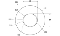
- Fig. 10 is a diagram showing a modified example of the non-burning flavor inhalation device 30A according to this modified example 1.
- Fig. 10 shows the surface on the mouth end 101 side of the non-burning flavor inhalation device 30A according to this modified example 1.
- Fig. 11 is a diagram showing the inflow path of air flowing into the tobacco stick 100 when the tobacco stick 100 is stored in the non-burning flavor inhalation device 30A according to this modified example 1.
- This modified example differs from the above-mentioned embodiment in that the internal space of the storage section 35A is elliptical cylindrical, but the other configurations are substantially the same. For this reason, the same elements are given the same reference numerals, and repeated explanations will be omitted.
- the tobacco stick 100 is cylindrical as in the above-mentioned embodiment, and the radial width is approximately the same as the width WA of the internal space in the storage section 35A and is narrower than the width WB in the major axis direction.
- a gap 353 is formed between the inner peripheral surface of the storage section 35A in the major axis direction and the outer peripheral surface of the tobacco stick 100. Therefore, in this modified non-combustion flavor inhalation device 30A, as shown in FIG. 11, the gap 353 when the tobacco stick 100 is inserted in a specified state serves as an air inflow path.
- an air flow path 36 is provided that penetrates from the outer peripheral surface of the housing 31 to the internal space of the storage section 35 in order to ensure that air flows into the tip 102 of the tobacco stick 100 inserted in the storage section 35.
- a gap 353 is formed between the inner peripheral surface of the storage section 35A and the outer peripheral surface of the tobacco stick 100, and this gap 353 serves as an air flow path to the tip 102 of the tobacco stick 100, so that the air flow path 36 in the above-mentioned embodiment can be omitted and simplification can be achieved.
- the first ventilation portion 431 facing the gap 353, i.e., the first ventilation portion 431 located in the major axis direction in the elliptical cross section of the storage section 35A, does not restrict the inflow of air, but the first ventilation portion 431 located in the minor axis direction contacts the inner peripheral surface of the storage section 35A and restricts the inflow of air.
- the tobacco stick 100 can be prevented from being mistaken for a conventional cigarette and erroneously ignited, and appropriate smoking can be performed when the tobacco stick 100 is inserted in the non-combustion type flavor inhalation device 30A.
- the air flow path 36 may not be omitted, and an air flow path by the air flow path 36 and the gap 353 may be used in combination to stably supply air to the tip 102 of the tobacco stick 100.
- the width WA of the tobacco stick 100 in the short axis direction in the internal space of the storage portion 35A is formed to be approximately the same as the width of the tobacco stick 100, but this is not limited thereto, and the tobacco stick 100 may be formed to be smaller than the width WA of the internal space, and when the tobacco stick 100 is stored in the storage portion 35A, the tobacco stick 100 may be compressed, thereby increasing the degree of contact between the outer peripheral surface of the tobacco stick 100 and the inner peripheral surface of the storage portion 35A.
- the flatness of the elliptical cross section of the storage section 35A may be set so that an air flow path is secured by a gap 353 between the inner peripheral surface in the long axis direction of the internal space of the storage section 35A and the outer peripheral surface of the tobacco stick 100.
- ⁇ Modification 2> 12 is a diagram showing a modified example of the non-combustion type flavor inhalation device 30B according to Modification 2.
- This modification is different from the above-described embodiment in that the area near the insertion opening 3A in the internal space of the storage section 35B is widened, and the second ventilation section 432 of the tobacco stick 100 is accommodated in this widened area, but the other configurations are substantially the same. For this reason, the same elements are denoted by the same reference numerals, and repeated explanations will be omitted.
- the storage section 35B of this modified example has an insertion opening 3A formed in a funnel shape, and the internal space is designed to continuously widen from the tip side toward the insertion opening 3A side.
- the shape of the storage section 35B is not limited to a funnel shape, and may be tapered or any other shape in which the internal space continuously widens toward the insertion opening 3A side.
- the second ventilation portion 432 when the tobacco stick 100 is in the specified insertion state, the second ventilation portion 432 is configured to be positioned outside the storage portion 35, but in this modified example, the second ventilation portion 432 is configured to be positioned within the widened portion 354 of the storage portion 35B. Even in this case, since the widened portion 354 is formed to be wider than the tobacco stick 100, the inflow of air through the second ventilation portion 432 is not restricted in the specified insertion state. In other words, the second ventilation portion 432 is not limited to being positioned outside the storage portion 35 in the specified insertion state (as in the above-described embodiment), but may be positioned in a position where the inflow of air is not restricted in the specified insertion state.
- the second ventilation section 432 is stored within the storage section 35B, but is located in the widened portion 354 and does not restrict the inflow of air, so that appropriate smoking can be provided in the specified storage state, as in the previous embodiment.
- the flavor stick of the present disclosure comprises: A flavor stick that is inserted into and removed from a storage section of a non-burning flavor inhalation device and is heated while being stored in the storage section, a flavor fill comprising a flavor source and an aerosol-forming substrate; A cylindrical member at least a portion of which is filled with the flavor filling, The cylindrical member is One end is the tip end and the other end is the mouth end, A ventilation portion is provided on a peripheral wall of the cylindrical member to allow air to flow from the outside to the internal space, The tip, the ventilation section, and the suction port end are communicated with each other so that air flowing in from the tip and the ventilation section is sucked out from the suction port end when suction is performed from the suction port end side, The ventilation portion is a first ventilation section in which the inflow of the air is restricted by an inner wall of the storage section when the tip side of the flavor stick is stored in the storage section in a specified state; and a second ventilation section which is located closer to the
- the ventilation portion may be an opening provided in the peripheral wall of the tubular member, or a portion of the peripheral wall formed from a breathable material.
- the flavor stick according to any one of the above aspects 1 to 3 includes a flavor rod portion filled with the flavor filling, and a mouthpiece portion disposed closer to the mouth end than the flavor rod portion,
- the first ventilation portion may be provided in at least one of the flavor rod portion and the mouthpiece portion.
- the first ventilation portion may be provided in the flavor rod portion.
- the flavor stick according to any one of Aspects 1 to 5 above may have an airflow resistance from the tip to the mouth end of 45 mmWG or less when not contained in the containing section, and the airflow resistance may be measured according to the ISO 9512 method.
- the flavor stick of Aspect 6 above may have an airflow resistance from the tip to the mouth end of 10 mmWG or more when not contained in the container.
- the non-combustion type flavor inhalation system of the present disclosure includes: A flavor stick according to any one of the above aspects 1 to 7, and a non-combustion type flavor inhalation device for heating the flavor stick,
- the non-burning flavor inhalation device comprises: a storage section capable of storing the flavor stick and having an inner wall that limits ventilation of the ventilation section when the flavor stick is stored therein; A heating unit that heats the flavor stick contained in the container; Equipped with.
- the heating unit may have an electric heater that generates heat when supplied with electric power, an induction coil that heats a heating body arranged within the flavor stick or around the flavor stick by electromagnetic induction, or a microwave generator that applies microwaves to the flavor stick to heat it.
Landscapes
- Manufacture Of Tobacco Products (AREA)
- Cigarettes, Filters, And Manufacturing Of Filters (AREA)
Priority Applications (3)
| Application Number | Priority Date | Filing Date | Title |
|---|---|---|---|
| JP2025506283A JPWO2024189732A1 (https=) | 2023-03-13 | 2023-03-13 | |
| PCT/JP2023/009584 WO2024189732A1 (ja) | 2023-03-13 | 2023-03-13 | 香味スティック及び非燃焼型香味吸引システム |
| EP23927354.3A EP4681558A1 (en) | 2023-03-13 | 2023-03-13 | Flavor stick and non-combustion type flavor inhalation system |
Applications Claiming Priority (1)
| Application Number | Priority Date | Filing Date | Title |
|---|---|---|---|
| PCT/JP2023/009584 WO2024189732A1 (ja) | 2023-03-13 | 2023-03-13 | 香味スティック及び非燃焼型香味吸引システム |
Publications (1)
| Publication Number | Publication Date |
|---|---|
| WO2024189732A1 true WO2024189732A1 (ja) | 2024-09-19 |
Family
ID=92754681
Family Applications (1)
| Application Number | Title | Priority Date | Filing Date |
|---|---|---|---|
| PCT/JP2023/009584 Ceased WO2024189732A1 (ja) | 2023-03-13 | 2023-03-13 | 香味スティック及び非燃焼型香味吸引システム |
Country Status (3)
| Country | Link |
|---|---|
| EP (1) | EP4681558A1 (https=) |
| JP (1) | JPWO2024189732A1 (https=) |
| WO (1) | WO2024189732A1 (https=) |
Citations (5)
| Publication number | Priority date | Publication date | Assignee | Title |
|---|---|---|---|---|
| JP2003527127A (ja) * | 2000-03-23 | 2003-09-16 | フィリップ・モーリス・プロダクツ・インコーポレイテッド | 電気喫煙システムと方法 |
| KR20200061290A (ko) * | 2018-11-23 | 2020-06-02 | 주식회사 케이티앤지 | 에어로졸 생성 물품 및 이를 수용하는 에어로졸 생성 장치 |
| WO2020230577A1 (ja) * | 2019-05-13 | 2020-11-19 | 日本たばこ産業株式会社 | 非燃焼加熱型香味吸引物品、及び、電気加熱型香味吸引システム |
| JP2021532765A (ja) * | 2018-07-31 | 2021-12-02 | ニコベンチャーズ トレーディング リミテッド | エアロゾルの生成 |
| WO2022128827A1 (en) * | 2020-12-17 | 2022-06-23 | Philip Morris Products S.A. | Aerosol-generating device, aerosol-generating article and aerosol-delivery system |
-
2023
- 2023-03-13 EP EP23927354.3A patent/EP4681558A1/en active Pending
- 2023-03-13 JP JP2025506283A patent/JPWO2024189732A1/ja active Pending
- 2023-03-13 WO PCT/JP2023/009584 patent/WO2024189732A1/ja not_active Ceased
Patent Citations (5)
| Publication number | Priority date | Publication date | Assignee | Title |
|---|---|---|---|---|
| JP2003527127A (ja) * | 2000-03-23 | 2003-09-16 | フィリップ・モーリス・プロダクツ・インコーポレイテッド | 電気喫煙システムと方法 |
| JP2021532765A (ja) * | 2018-07-31 | 2021-12-02 | ニコベンチャーズ トレーディング リミテッド | エアロゾルの生成 |
| KR20200061290A (ko) * | 2018-11-23 | 2020-06-02 | 주식회사 케이티앤지 | 에어로졸 생성 물품 및 이를 수용하는 에어로졸 생성 장치 |
| WO2020230577A1 (ja) * | 2019-05-13 | 2020-11-19 | 日本たばこ産業株式会社 | 非燃焼加熱型香味吸引物品、及び、電気加熱型香味吸引システム |
| WO2022128827A1 (en) * | 2020-12-17 | 2022-06-23 | Philip Morris Products S.A. | Aerosol-generating device, aerosol-generating article and aerosol-delivery system |
Also Published As
| Publication number | Publication date |
|---|---|
| JPWO2024189732A1 (https=) | 2024-09-19 |
| EP4681558A1 (en) | 2026-01-21 |
Similar Documents
| Publication | Publication Date | Title |
|---|---|---|
| JP7627800B2 (ja) | 非燃焼加熱式たばこ製品 | |
| US20230380493A1 (en) | Heat-not-burn tobacco product and heat-not-burn tobacco stick | |
| WO2024189732A1 (ja) | 香味スティック及び非燃焼型香味吸引システム | |
| JP7640582B2 (ja) | 非燃焼加熱式たばこ及び電気加熱式たばこ製品 | |
| JP7659576B2 (ja) | 非燃焼加熱式たばこ及び電気加熱式たばこ製品 | |
| JP7522863B2 (ja) | 非燃焼加熱式たばこ及び電気加熱式たばこ製品 | |
| WO2025243507A1 (ja) | 香味発生物品および香味発生システム | |
| EP4691280A1 (en) | Non-combustion type flavor inhalation article and non-combustion type flavor inhalation system | |
| WO2025126308A1 (ja) | 香味発生物品 | |
| WO2025203565A1 (ja) | 香味発生物品および香味発生システム | |
| WO2025052620A1 (ja) | 香味発生物品 | |
| JP2025135077A (ja) | 香味発生物品 | |
| WO2025052611A1 (ja) | 香味発生物品および香味発生システム | |
| WO2025052612A1 (ja) | 香味発生物品および香味発生システム | |
| WO2025052613A1 (ja) | 香味発生物品および香味発生システム | |
| WO2025186891A1 (ja) | 香味発生物品 | |
| TW202604375A (zh) | 風味產生製品和風味產生系統 | |
| WO2025154253A1 (ja) | 香味発生物品 | |
| WO2025154254A1 (ja) | 香味発生物品および香味発生物品の製造方法 | |
| WO2025052617A1 (ja) | 香味発生物品 | |
| WO2025052618A1 (ja) | 香味発生物品及び喫煙システム | |
| WO2025052625A1 (ja) | 香味発生物品 | |
| WO2025154255A1 (ja) | 香味吸引システム | |
| WO2025126307A1 (ja) | 香味発生システム |
Legal Events
| Date | Code | Title | Description |
|---|---|---|---|
| 121 | Ep: the epo has been informed by wipo that ep was designated in this application |
Ref document number: 23927354 Country of ref document: EP Kind code of ref document: A1 |
|
| ENP | Entry into the national phase |
Ref document number: 2025506283 Country of ref document: JP Kind code of ref document: A |
|
| WWE | Wipo information: entry into national phase |
Ref document number: 2025506283 Country of ref document: JP |
|
| WWE | Wipo information: entry into national phase |
Ref document number: 2023927354 Country of ref document: EP |
|
| NENP | Non-entry into the national phase |
Ref country code: DE |
|
| ENP | Entry into the national phase |
Ref document number: 2023927354 Country of ref document: EP Effective date: 20251013 |
|
| ENP | Entry into the national phase |
Ref document number: 2023927354 Country of ref document: EP Effective date: 20251013 |
|
| ENP | Entry into the national phase |
Ref document number: 2023927354 Country of ref document: EP Effective date: 20251013 |
|
| ENP | Entry into the national phase |
Ref document number: 2023927354 Country of ref document: EP Effective date: 20251013 |
|
| ENP | Entry into the national phase |
Ref document number: 2023927354 Country of ref document: EP Effective date: 20251013 |