WO2024185753A1 - ヒートパイプ及びヒートシンク - Google Patents
ヒートパイプ及びヒートシンク Download PDFInfo
- Publication number
- WO2024185753A1 WO2024185753A1 PCT/JP2024/008177 JP2024008177W WO2024185753A1 WO 2024185753 A1 WO2024185753 A1 WO 2024185753A1 JP 2024008177 W JP2024008177 W JP 2024008177W WO 2024185753 A1 WO2024185753 A1 WO 2024185753A1
- Authority
- WO
- WIPO (PCT)
- Prior art keywords
- heat
- heat pipe
- container
- working fluid
- pipe according
- Prior art date
- Legal status (The legal status is an assumption and is not a legal conclusion. Google has not performed a legal analysis and makes no representation as to the accuracy of the status listed.)
- Ceased
Links
Images







Classifications
-
- F—MECHANICAL ENGINEERING; LIGHTING; HEATING; WEAPONS; BLASTING
- F28—HEAT EXCHANGE IN GENERAL
- F28D—HEAT-EXCHANGE APPARATUS, NOT PROVIDED FOR IN ANOTHER SUBCLASS, IN WHICH THE HEAT-EXCHANGE MEDIA DO NOT COME INTO DIRECT CONTACT
- F28D15/00—Heat-exchange apparatus with the intermediate heat-transfer medium in closed tubes passing into or through the conduit walls ; Heat-exchange apparatus employing intermediate heat-transfer medium or bodies
- F28D15/02—Heat-exchange apparatus with the intermediate heat-transfer medium in closed tubes passing into or through the conduit walls ; Heat-exchange apparatus employing intermediate heat-transfer medium or bodies in which the medium condenses and evaporates, e.g. heat pipes
- F28D15/04—Heat-exchange apparatus with the intermediate heat-transfer medium in closed tubes passing into or through the conduit walls ; Heat-exchange apparatus employing intermediate heat-transfer medium or bodies in which the medium condenses and evaporates, e.g. heat pipes with tubes having a capillary structure
- F28D15/046—Heat-exchange apparatus with the intermediate heat-transfer medium in closed tubes passing into or through the conduit walls ; Heat-exchange apparatus employing intermediate heat-transfer medium or bodies in which the medium condenses and evaporates, e.g. heat pipes with tubes having a capillary structure characterised by the material or the construction of the capillary structure
-
- F—MECHANICAL ENGINEERING; LIGHTING; HEATING; WEAPONS; BLASTING
- F28—HEAT EXCHANGE IN GENERAL
- F28D—HEAT-EXCHANGE APPARATUS, NOT PROVIDED FOR IN ANOTHER SUBCLASS, IN WHICH THE HEAT-EXCHANGE MEDIA DO NOT COME INTO DIRECT CONTACT
- F28D15/00—Heat-exchange apparatus with the intermediate heat-transfer medium in closed tubes passing into or through the conduit walls ; Heat-exchange apparatus employing intermediate heat-transfer medium or bodies
- F28D15/02—Heat-exchange apparatus with the intermediate heat-transfer medium in closed tubes passing into or through the conduit walls ; Heat-exchange apparatus employing intermediate heat-transfer medium or bodies in which the medium condenses and evaporates, e.g. heat pipes
- F28D15/04—Heat-exchange apparatus with the intermediate heat-transfer medium in closed tubes passing into or through the conduit walls ; Heat-exchange apparatus employing intermediate heat-transfer medium or bodies in which the medium condenses and evaporates, e.g. heat pipes with tubes having a capillary structure
-
- F—MECHANICAL ENGINEERING; LIGHTING; HEATING; WEAPONS; BLASTING
- F28—HEAT EXCHANGE IN GENERAL
- F28D—HEAT-EXCHANGE APPARATUS, NOT PROVIDED FOR IN ANOTHER SUBCLASS, IN WHICH THE HEAT-EXCHANGE MEDIA DO NOT COME INTO DIRECT CONTACT
- F28D15/00—Heat-exchange apparatus with the intermediate heat-transfer medium in closed tubes passing into or through the conduit walls ; Heat-exchange apparatus employing intermediate heat-transfer medium or bodies
- F28D15/02—Heat-exchange apparatus with the intermediate heat-transfer medium in closed tubes passing into or through the conduit walls ; Heat-exchange apparatus employing intermediate heat-transfer medium or bodies in which the medium condenses and evaporates, e.g. heat pipes
- F28D15/0233—Heat-exchange apparatus with the intermediate heat-transfer medium in closed tubes passing into or through the conduit walls ; Heat-exchange apparatus employing intermediate heat-transfer medium or bodies in which the medium condenses and evaporates, e.g. heat pipes the conduits having a particular shape, e.g. non-circular cross-section, annular
-
- F—MECHANICAL ENGINEERING; LIGHTING; HEATING; WEAPONS; BLASTING
- F28—HEAT EXCHANGE IN GENERAL
- F28F—DETAILS OF HEAT-EXCHANGE AND HEAT-TRANSFER APPARATUS, OF GENERAL APPLICATION
- F28F1/00—Tubular elements; Assemblies of tubular elements
- F28F1/02—Tubular elements of cross-section which is non-circular
- F28F1/06—Tubular elements of cross-section which is non-circular crimped or corrugated in cross-section
-
- F—MECHANICAL ENGINEERING; LIGHTING; HEATING; WEAPONS; BLASTING
- F28—HEAT EXCHANGE IN GENERAL
- F28F—DETAILS OF HEAT-EXCHANGE AND HEAT-TRANSFER APPARATUS, OF GENERAL APPLICATION
- F28F1/00—Tubular elements; Assemblies of tubular elements
- F28F1/10—Tubular elements and assemblies thereof with means for increasing heat-transfer area, e.g. with fins, with projections, with recesses
- F28F1/40—Tubular elements and assemblies thereof with means for increasing heat-transfer area, e.g. with fins, with projections, with recesses the means being only inside the tubular element
-
- F—MECHANICAL ENGINEERING; LIGHTING; HEATING; WEAPONS; BLASTING
- F28—HEAT EXCHANGE IN GENERAL
- F28F—DETAILS OF HEAT-EXCHANGE AND HEAT-TRANSFER APPARATUS, OF GENERAL APPLICATION
- F28F13/00—Arrangements for modifying heat-transfer, e.g. increasing, decreasing
- F28F13/02—Arrangements for modifying heat-transfer, e.g. increasing, decreasing by influencing fluid boundary
-
- H—ELECTRICITY
- H10—SEMICONDUCTOR DEVICES; ELECTRIC SOLID-STATE DEVICES NOT OTHERWISE PROVIDED FOR
- H10W—GENERIC PACKAGES, INTERCONNECTIONS, CONNECTORS OR OTHER CONSTRUCTIONAL DETAILS OF DEVICES COVERED BY CLASS H10
- H10W40/00—Arrangements for thermal protection or thermal control
- H10W40/70—Fillings or auxiliary members in containers or in encapsulations for thermal protection or control
- H10W40/73—Fillings or auxiliary members in containers or in encapsulations for thermal protection or control for cooling by change of state
-
- F—MECHANICAL ENGINEERING; LIGHTING; HEATING; WEAPONS; BLASTING
- F28—HEAT EXCHANGE IN GENERAL
- F28D—HEAT-EXCHANGE APPARATUS, NOT PROVIDED FOR IN ANOTHER SUBCLASS, IN WHICH THE HEAT-EXCHANGE MEDIA DO NOT COME INTO DIRECT CONTACT
- F28D15/00—Heat-exchange apparatus with the intermediate heat-transfer medium in closed tubes passing into or through the conduit walls ; Heat-exchange apparatus employing intermediate heat-transfer medium or bodies
- F28D15/02—Heat-exchange apparatus with the intermediate heat-transfer medium in closed tubes passing into or through the conduit walls ; Heat-exchange apparatus employing intermediate heat-transfer medium or bodies in which the medium condenses and evaporates, e.g. heat pipes
- F28D2015/0216—Heat-exchange apparatus with the intermediate heat-transfer medium in closed tubes passing into or through the conduit walls ; Heat-exchange apparatus employing intermediate heat-transfer medium or bodies in which the medium condenses and evaporates, e.g. heat pipes having particular orientation, e.g. slanted, or being orientation-independent
-
- F—MECHANICAL ENGINEERING; LIGHTING; HEATING; WEAPONS; BLASTING
- F28—HEAT EXCHANGE IN GENERAL
- F28D—HEAT-EXCHANGE APPARATUS, NOT PROVIDED FOR IN ANOTHER SUBCLASS, IN WHICH THE HEAT-EXCHANGE MEDIA DO NOT COME INTO DIRECT CONTACT
- F28D21/00—Heat-exchange apparatus not covered by any of the groups F28D1/00 - F28D20/00
- F28D2021/0019—Other heat exchangers for particular applications; Heat exchange systems not otherwise provided for
- F28D2021/0028—Other heat exchangers for particular applications; Heat exchange systems not otherwise provided for for cooling heat generating elements, e.g. for cooling electronic components or electric devices
- F28D2021/0029—Heat sinks
-
- F—MECHANICAL ENGINEERING; LIGHTING; HEATING; WEAPONS; BLASTING
- F28—HEAT EXCHANGE IN GENERAL
- F28F—DETAILS OF HEAT-EXCHANGE AND HEAT-TRANSFER APPARATUS, OF GENERAL APPLICATION
- F28F1/00—Tubular elements; Assemblies of tubular elements
- F28F1/10—Tubular elements and assemblies thereof with means for increasing heat-transfer area, e.g. with fins, with projections, with recesses
- F28F1/12—Tubular elements and assemblies thereof with means for increasing heat-transfer area, e.g. with fins, with projections, with recesses the means being only outside the tubular element
- F28F1/24—Tubular elements and assemblies thereof with means for increasing heat-transfer area, e.g. with fins, with projections, with recesses the means being only outside the tubular element and extending transversely
-
- F—MECHANICAL ENGINEERING; LIGHTING; HEATING; WEAPONS; BLASTING
- F28—HEAT EXCHANGE IN GENERAL
- F28F—DETAILS OF HEAT-EXCHANGE AND HEAT-TRANSFER APPARATUS, OF GENERAL APPLICATION
- F28F2265/00—Safety or protection arrangements; Arrangements for preventing malfunction
- F28F2265/14—Safety or protection arrangements; Arrangements for preventing malfunction for preventing damage by freezing, e.g. for accommodating volume expansion
-
- H—ELECTRICITY
- H10—SEMICONDUCTOR DEVICES; ELECTRIC SOLID-STATE DEVICES NOT OTHERWISE PROVIDED FOR
- H10W—GENERIC PACKAGES, INTERCONNECTIONS, CONNECTORS OR OTHER CONSTRUCTIONAL DETAILS OF DEVICES COVERED BY CLASS H10
- H10W40/00—Arrangements for thermal protection or thermal control
- H10W40/20—Arrangements for cooling
- H10W40/22—Arrangements for cooling characterised by their shape, e.g. having conical or cylindrical projections
- H10W40/226—Arrangements for cooling characterised by their shape, e.g. having conical or cylindrical projections characterised by projecting parts, e.g. fins to increase surface area
Definitions
- the present invention relates to a heat pipe and a heat sink equipped with a heat pipe that can prevent freezing of the working fluid and exhibit excellent flow characteristics even in low-temperature environments.
- Heat pipes are sometimes used as a means of cooling electronic components.
- Water is sometimes used as the working fluid for heat pipes.
- the heat pipe when the heating element that is the object of cooling by the heat pipe is mounted on equipment exposed to the external environment, the heat pipe will be used in a low-temperature environment.
- the water that serves as the working fluid freezes, preventing the heat pipe from operating properly and reducing the heat transport function of the heat pipe.
- Patent Document 1 a gravity heat pipe using hydrofluoroolefin has been proposed as an environmentally friendly working fluid that can prevent freezing even in low-temperature environments.
- the gravity heat pipe of Patent Document 1 is a loop-type heat pipe in which the working fluid that has changed phase from liquid to gas in the evaporator flows from the evaporator to the condenser through a vapor pipe, and the working fluid that has changed phase from gas to liquid in the condenser by releasing latent heat returns from the condenser to the evaporator through a liquid return pipe. That is, in Patent Document 1, the liquid-phase working fluid returns from the condenser to the evaporator by the action of gravity.
- the heat pipe needs to be installed so that the liquid phase working fluid flows from above to below in the direction of gravity, and furthermore, the area where the gas phase working fluid flows and the area where the liquid phase working fluid flows need to be separated, which causes problems such as a significant restriction in the freedom of installation of the heat pipe, and the inability to install it in a small space due to space-saving.
- Patent Document 1 in order to prevent restrictions on the degree of freedom in installing the heat pipe, a single pipe is used as both the steam pipe and the liquid return pipe. However, this causes the gas-phase working fluid and the liquid-phase working fluid to flow in countercurrents through the shared pipe, resulting in the problem of impeding the flow of the working fluid.
- the present invention aims to provide a heat pipe that can prevent freezing of the working fluid and exhibit excellent flow characteristics even in a low-temperature operating environment, while also enabling space saving and improved freedom of installation, and a heat sink equipped with the heat pipe.
- the gist of the configuration of the present invention is as follows. [1] A container having one end and another end opposite to the one end, with an end face of the one end and an end face of the other end sealed; a wick structure disposed inside the container; A working fluid enclosed within the container; and A heat pipe comprising: The wick structure has narrow grooves provided on the inner surface of the container and/or a porous body provided on the inner surface of the container, The heat pipe, wherein the working fluid comprises a hydrofluoroolefin.
- the hydrofluoroolefin is at least one selected from the group consisting of cis-1,3,3,3-tetrafluoroprop-1-ene, trans-1,3,3,3-tetrafluoroprop-1-ene, 2,3,3,3-tetrafluoropropene, (Z)-1,1,1,4,4,4-hexafluorobutene, (E)-1,1,1,4,4,4-hexafluorobutene, trans-1-chloro-3,3,3-trifluoropropene, (Z)-1-chloro-3,3,3-trifluoropropene and 1-chloro-2,3,3-trifluoropropene.
- the heat pipe according to the present invention is at least one selected from the group consisting of cis-1,3,3,3-tetrafluoroprop-1-ene, trans-1,3,3,3-tetrafluoroprop-1-ene, 2,3,3,3-tetrafluoropropene, (Z)-1
- the heat pipe according to [11], wherein the straight portion is a portion to which a heat generating element to be cooled is thermally connected.
- the heat sink according to [20] further comprising a heat receiving block thermally connected to a second region which is another partial region of the container.
- the heat sink according to [20] wherein the temperature of the usage environment is ⁇ 50° C. or higher and 90° C. or lower.
- the working fluid has a cross-sectional area that is 50% or more of the cross-sectional area of the internal space of the container
- the working fluid contains hydrofluoroolefin, which reduces the burden on the environment and prevents freezing of the working fluid even in a low-temperature usage environment, thereby exhibiting excellent flow characteristics.
- the heat pipe includes a container having one end and the other end opposite the one end, with the end face of the one end and the end face of the other end sealed, a wick structure provided inside the container, and a working fluid sealed inside the container, and the wick structure has fine grooves provided on the inner surface of the container and/or a porous body provided on the inner surface of the container, so that it is not a loop-type heat pipe and it is not necessary for the liquid phase working fluid to circulate by gravity, which makes it possible to save space and improve the freedom of installation.
- the hydrofluoroolefin is at least one selected from the group consisting of cis-1,3,3,3-tetrafluoroprop-1-ene, trans-1,3,3,3-tetrafluoroprop-1-ene, 2,3,3,3-tetrafluoropropene, (Z)-1,1,1,4,4,4-hexafluorobutene, (E)-1,1,1,4,4,4-hexafluorobutene, trans-1-chloro-3,3,3-trifluoropropene, (Z)-1-chloro-3,3,3-trifluoropropene, and 1-chloro-2,3,3-trifluoropropene, so that freezing of the working fluid can be more reliably prevented even in a low-temperature operating environment, and the heat transport properties of the heat pipe are improved.
- the hydrofluoroolefin is trans-1,3,3,3-tetrafluoroprop-1-ene, which further improves the heat transport properties of the heat pipe.
- the critical point temperature of the working fluid is 100°C or higher, so that the heat pipe can reliably obtain heat transport properties even when used in a high-temperature environment.
- the heat pipe of the present invention by containing water and/or alcohol in addition to the hydrofluoroolefin, it is possible to obtain even better heat transport properties than when the working fluid is made of hydrofluoroolefin.
- the excellent heat transport properties refer to the amount of heat transport, and the reduction in the amount of heat transport caused by changes in the container shape is prevented.
- water freezes at low temperatures by using water and hydrofluoroolefin in combination, the melting of water is promoted by the heat transport action of the hydrofluoroolefin, so that the properties of water, which has excellent heat transport properties, can also be exhibited.
- the working fluid when the longitudinal shape of the container is linear and the longitudinal direction of the container is perpendicular to the direction of gravity, the working fluid has a cross-sectional area of 50% or more of the cross-sectional area of the internal space of the container in at least one cross section perpendicular to the longitudinal direction of the container, thereby further improving the heat transport properties of the heat pipe.
- the longitudinal shape of the container has straight and bent portions, and when the longitudinal direction of the straight portion is perpendicular to the direction of gravity, the working fluid has a cross-sectional area of 50% or more of the cross-sectional area of the internal space of the straight portion in at least one cross section perpendicular to the longitudinal direction of the straight portion, thereby further improving the heat transport properties of the heat pipe.
- the wick structure is a narrow groove provided on the inner surface of the container, and the shape of the narrow groove in a direction perpendicular to the longitudinal direction of the container is rectangular, triangular, or trapezoidal, thereby ensuring a flow path for the gas phase working fluid while ensuring the reflux characteristics of the liquid phase working fluid.
- the narrow grooves are rectangular in shape, the depth (H) of the narrow grooves is 0.15 mm or more and 0.50 mm or less, and the width (W) of the narrow grooves is 0.15 mm or more and 0.60 mm or less, thereby improving the reflux characteristics of the liquid phase working fluid and further improving the heat transport characteristics of the heat pipe.
- the narrow grooves are triangular in shape, the depth (H) of the narrow grooves is 0.15 mm or more and 0.50 mm or less, and the width (W) at 1/2 the depth (H) of the narrow grooves ((1/2)H) is 0.15 mm or more and 1.00 mm or less, thereby improving the reflux characteristics of the liquid-phase working fluid and further improving the heat transport characteristics of the heat pipe.
- the narrow grooves are trapezoidal in shape, the depth (H) of the narrow grooves is 0.15 mm or more and 0.50 mm or less, and the average width (W) of the narrow grooves is 0.05 mm or more and 1.00 mm or less, thereby improving the reflux characteristics of the liquid-phase working fluid and further improving the heat transport characteristics of the heat pipe.
- the heat sink of the present invention by having the heat pipe and a heat dissipation fin thermally connected to a first region that is a partial region of the container of the heat pipe, it is possible to prevent the working fluid of the heat pipe from freezing even in a low-temperature operating environment, thereby exhibiting excellent flow characteristics of the working fluid, and also to reduce space and improve the flexibility of installation.
- FIG. 10 is an explanatory diagram of a third shape of the narrow grooves in a cross section perpendicular to the longitudinal direction of the heat pipe according to the first embodiment of the present invention.
- FIG. FIG. 11 is an explanatory diagram showing an overview of a heat pipe according to a second embodiment of the present invention in the longitudinal direction.
- FIG. 11 is an explanatory diagram showing a plan view of a heat pipe according to a third embodiment of the present invention.
- 1 is a plan view showing an overview of a heat sink according to a first embodiment of the present invention
- 1 is a side view showing an overview of a heat sink according to a first embodiment of the present invention
- FIG. 11 is a plan view showing an overview of a heat sink according to a second embodiment of the present invention.
- FIG. 11 is a side view showing an overview of a heat sink according to a second embodiment of the present invention.
- FIG. 11 is a plan view showing an overview of a heat sink according to a third embodiment of the present invention.
- FIG. 11 is a side view showing an overview of a heat sink according to a third embodiment of the present invention.
- FIG. 13 is a plan view showing an overview of a heat sink according to a fourth embodiment of the present invention.
- FIG. 10 is a side view showing an overview of a heat sink according to a fourth embodiment of the present invention.
- FIG. 13 is a plan view showing an outline of a heat sink according to a fifth embodiment of the present invention.
- FIG. 13 is a side view showing an overview of a heat sink according to a fifth embodiment of the present invention.
- FIG. 11 is a side view showing an overview of a heat sink according to a fifth embodiment of the present invention.
- FIG. 13 is a plan view showing an outline of a heat sink according to a sixth embodiment of the present invention.
- FIG. 13 is a side view showing an overview of a heat sink according to a sixth embodiment of the present invention.
- FIG. 13 is a plan view showing an outline of a heat sink according to a seventh embodiment of the present invention.
- FIG. 13 is a side view showing an overview of a heat sink according to a seventh embodiment of the present invention.
- FIG. 13 is a side view showing an overview of a heat sink according to an eighth embodiment of the present invention.
- FIG. 13 is a side view showing an overview of a heat sink according to a ninth embodiment of the present invention.
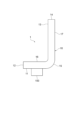
- FIG. 1 is an explanatory diagram showing an overview of the heat pipe according to the first embodiment of the present invention in the longitudinal direction.
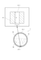
- FIG. 2 is an explanatory diagram showing an overview of the cross section in a direction perpendicular to the longitudinal direction of the heat pipe according to the first embodiment of the present invention.
- FIG. 3 is an explanatory diagram of a first shape of the narrow grooves in the cross section in a direction perpendicular to the longitudinal direction of the heat pipe according to the first embodiment of the present invention.
- FIG. 1 is an explanatory diagram showing an overview of the heat pipe according to the first embodiment of the present invention in the longitudinal direction.
- FIG. 2 is an explanatory diagram showing an overview of the cross section in a direction perpendicular to the longitudinal direction of the heat pipe according to the first embodiment of the present invention.
- FIG. 3 is an explanatory diagram of a first shape of the narrow grooves in the cross section in a direction perpendicular to the longitudinal direction of the heat pipe according to the first embodiment of the present invention.
- FIG. 4 is an explanatory diagram of a second shape of the narrow grooves in the cross section in a direction perpendicular to the longitudinal direction of the heat pipe according to the first embodiment of the present invention.
- FIG. 5 is an explanatory diagram of a third shape of the narrow grooves in the cross section in a direction perpendicular to the longitudinal direction of the heat pipe according to the first embodiment of the present invention.
- the heat pipe 1 has one end 11 and the other end 13 opposite the one end 11, and includes a container 10 in which the end face 12 of the one end 11 and the end face 14 of the other end 13 are sealed, a wick structure 20 provided inside the container 10, and a working fluid 30 sealed inside the container 10.
- the heat pipe 1 is not a loop-type heat pipe, and the gas-phase working fluid and the liquid-phase working fluid flow in a countercurrent relationship through the cavity 18, which is the internal space of the same container 10.
- the cavity 18, which is the internal space of the container 10, is an enclosed space that has been subjected to a reduced pressure treatment.
- the working fluid 30 sealed in the cavity 18 contains a hydrofluoroolefin. Therefore, the heat pipe 1 contains a hydrofluoroolefin as the working fluid 30.
- the working fluid 30 contains hydrofluoroolefin, which reduces the burden on the environment and prevents the working fluid 30 from freezing even in low-temperature operating environments, thereby providing excellent flow characteristics.
- the hydrofluoroolefin is not particularly limited, but from the viewpoints of more reliably preventing the freezing of the working fluid 30 even in a low-temperature usage environment and improving the heat transport characteristics of the heat pipe 1, preferred are cis-1,3,3,3-tetrafluoroprop-1-ene (HFO-1234ze(Z), CH 3 CH ⁇ CHF), trans-1,3,3,3-tetrafluoroprop-1-ene (HFO-1234ze(E), CH 3 CH ⁇ CHF), 2,3,3,3-tetrafluoropropene (HFO-1234yf, CH 2 ⁇ CFCF 3 ), (Z)-1,1,1,4,4,4-hexafluorobutene (HFO-1336mzz(Z), (Z)-CF 3 CF ⁇ CHCF 3 ), (E)-1,1,1,4,4,4-hexafluorobutene (HFO-1336mzz(E), (E)-CF 3 CF ⁇ CHCF 3 ), 1-chloro-2,3,3,3-
- trans-1,3,3,3-tetrafluoroprop-1-ene is particularly preferred because it further improves the heat transport properties of the heat pipe 1.
- the critical point temperature of the working fluid 30 containing hydrofluoroolefin is not particularly limited, but is preferably 100°C or higher, and particularly preferably 105°C or higher, because even if the environment in which the heat pipe 1 is used is high temperature, smooth phase changes between the gas phase and the liquid phase are maintained and the heat transport characteristics of the heat pipe 1 can be reliably obtained.
- the critical point of cis-1,3,3,3-tetrafluoroprop-1-ene (HFO-1234ze(Z), CH 3 CH ⁇ CHF) is 153°C
- that of trans-1,3,3,3-tetrafluoroprop-1-ene (HFO-1234ze(E), CH 3 CH ⁇ CHF) is 109°C
- that of 2,3,3,3-tetrafluoropropene (HFO-1234yf, CH 2 ⁇ CFCF 3 ) is 95°C
- that of (Z)-1,1,1,4,4,4-hexafluorobutene (HFO-1336mzz(Z), (Z)-CF 3 CF ⁇ CHCF 3 ) has a critical point temperature of 171° C.
- (E)-1,1,1,4,4,4-hexafluorobutene (HFO-1336mzz(E), (E)-CF 3 CF ⁇ CHCF 3 ) has a critical point temperature of 138° C.
- the working fluid 30 contains a hydrofluoroolefin. Therefore, in the heat pipe 1, it is sufficient that the working fluid 30 contains a hydrofluoroolefin. From the above, in the heat pipe of the present invention, the working fluid 30 may consist of only hydrofluoroolefin (i.e., the blending ratio of hydrofluoroolefin in the working fluid 30 is 100% by mass), or the working fluid 30 may contain hydrofluoroolefin and another fluid.
- the blending ratio of hydrofluoroolefin in the working fluid 30 is preferably 3% by mass or more and 70% by mass or less, and particularly preferably 3% by mass or more and 45% by mass or less, in order to improve the anti-freezing and heat transport properties of the working fluid 30 in a well-balanced manner.
- other fluids that can be used in combination with hydrofluoroolefin include water, alcohol, and mixtures of water and alcohol.
- the melting of water is promoted by the heat transport action of the hydrofluoroolefin, so that the properties of water, which has excellent heat transport properties, can also be exhibited.
- the blending ratio of hydrofluoroolefin is preferably less than 30 mass%.
- the container 10 is a tube.
- the shape of the container 10 is long.
- the longitudinal shape of the container 10 can be appropriately selected depending on the usage situation, etc., and may be straight or have a shape with a bent portion, but in the heat pipe 1, the longitudinal shape is a shape with a bent portion.
- the longitudinal shape of the container 10 of the heat pipe 1 is a roughly L-shape having one bent portion 15 and two straight portions connected via the bent portion 15.
- the two straight portions are straight portion 16 having one end 11 and straight portion 17 having the other end 13. Therefore, the heat pipe 1 is an L-shaped heat pipe.
- the wick structure 20 extends along the longitudinal direction of the container 10 from one end 11 to the other end 13 of the container 10.
- the heat pipe 1 functions as an evaporator section, for example, by thermally connecting the heating element 100 to the straight section 16 having one end 11, and functions as a condenser section, by thermally connecting a heat exchange means (not shown in Figures 1 and 2) to the straight section 17 having the other end 13. From the above, the wick structure 20 extends along the heat transport direction of the heat pipe 1.
- the wick structure 20 may be, for example, a fine groove provided on the inner surface of the container 10, or a porous body provided on the inner surface of the container 10.
- the wick structure 20 may be only a fine groove provided on the inner surface of the container 10, or only a porous body provided on the inner surface of the container 10, or may be a composite having a fine groove provided on the inner surface of the container 10 and a porous body formed on the fine groove.
- An example of the porous body is a sintered body in which metal powder such as copper powder is sintered.
- the shape of the porous body may be a porous body layer formed in a layer on the inner surface of the container 10.
- the wick structure 20 is a plurality of fine grooves 21, 21, 21... provided on the inner surface of the container 10.
- the plurality of fine grooves 21, 21, 21... extend from one end 11 to the other end 13 along the longitudinal direction of the container 10.
- the plurality of fine grooves 21, 21, 21... are formed on the entire inner surface of the container 10.
- a porous wick structure is not provided, and the plurality of fine grooves 21, 21, 21... are exposed to the hollow portion 18 of the container 10.
- the shape of the narrow grooves 21 in the direction perpendicular to the longitudinal direction of the container 10 is not particularly limited, and examples include a first shape of multiple narrow grooves 21-1, 21-1, 21-1... that are rectangular in shape in the direction perpendicular to the longitudinal direction of the container 10 as shown in Figures 2 and 3, a second shape of multiple narrow grooves 21-2, 21-2, 21-2... that are triangular in shape in the direction perpendicular to the longitudinal direction of the container 10 as shown in Figure 4, and a third shape of multiple narrow grooves 21-3, 21-3, 21-3... that are trapezoidal in shape in the direction perpendicular to the longitudinal direction of the container 10 as shown in Figure 5.
- the shape of the narrow grooves 21 in the direction perpendicular to the longitudinal direction of the container 10 is rectangular, triangular, or trapezoidal, so that the reflux characteristics of the liquid-phase working fluid can be reliably obtained.
- the depth (H) of the narrow groove 21-1 is not particularly limited, but is preferably 0.15 mm or more and 0.50 mm or less, more preferably 0.30 mm or more and 0.50 mm or less, and particularly preferably 0.35 mm or more and 0.45 mm or less, in terms of ease of forming the narrow groove 21-1, improving the reflux characteristics of the liquid phase working fluid 30 containing hydrofluoroolefin, and further improving the heat transport characteristics of the heat pipe 1.
- the width (W) of the narrow groove 21-1 is not particularly limited, but is preferably 0.15 mm or more and 0.60 mm or less, more preferably 0.15 mm or more and 0.40 mm or less, and particularly preferably 0.15 mm or more and 0.35 mm or less, in terms of ease of forming the narrow groove 21-1, improving the reflux characteristics of the liquid phase working fluid 30 containing hydrofluoroolefin, and further improving the heat transport characteristics of the heat pipe 1.
- the depth (H) of the narrow groove 21-2 is not particularly limited, but is preferably 0.15 mm or more and 0.50 mm or less, more preferably 0.30 mm or more and 0.50 mm or less, and particularly preferably 0.35 mm or more and 0.45 mm or less, in terms of ease of forming the narrow groove 21-2, improving the reflux characteristics of the liquid phase working fluid 30 containing hydrofluoroolefin, and further improving the heat transport characteristics of the heat pipe 1.
- the width (W) at 1/2 the depth (H) of the narrow groove 21-2 ((1/2)H) is not particularly limited, but is preferably 0.15 mm or more and 1.00 mm or less, more preferably 0.15 mm or more and 0.90 mm or less, and particularly preferably 0.15 mm or more and 0.80 mm or less, in terms of ease of forming the narrow groove 21-2, improving the reflux characteristics of the liquid phase working fluid 30 containing hydrofluoroolefin, and further improving the heat transport characteristics of the heat pipe 1.
- the depth (H) of the narrow grooves 21-3 is not particularly limited, but is preferably 0.15 mm to 0.50 mm, more preferably 0.30 mm to 0.50 mm, and particularly preferably 0.35 mm to 0.45 mm, in terms of ease of forming the narrow grooves 21-3, improving the reflux characteristics of the liquid phase working fluid 30 containing hydrofluoroolefin, and further improving the heat transport characteristics of the heat pipe 1.
- the average width (W) of the narrow grooves 21-3 is not particularly limited, but is preferably 0.05 mm to 1.00 mm, more preferably 0.15 mm to 0.90 mm, and particularly preferably 0.15 mm to 0.80 mm, in terms of ease of forming the narrow grooves 21-3, improving the reflux characteristics of the liquid phase working fluid 30 containing hydrofluoroolefin, and further improving the heat transport characteristics of the heat pipe 1.
- the cross-sectional shape of the container 10 in a direction perpendicular to the longitudinal direction is not particularly limited, but as shown in Figures 2 to 5, the container 10 of the heat pipe 1 has a substantially circular shape.
- the thickness of the container 10 is not particularly limited, and is, for example, 0.1 mm or more and 0.7 mm or less.
- the inner diameter of the container 10, i.e., the diameter of the hollow portion 18, is not particularly limited, and is, for example, 3.0 mm or more and 32 mm or less.
- the longitudinal shape of the container 10 has a straight portion and a bent portion, specifically, a substantially L-shape formed with one bent portion 15, a straight portion 16 having one end 11 via the bent portion 15, and a straight portion 17 having the other end 13.
- the amount of the working fluid 30 to be enclosed is not particularly limited, but in order to impart excellent heat transport properties to the heat pipe 1, it is preferable that the amount of the working fluid 30 enclosed has a cross-sectional area of 40% or more of the cross-sectional area of the hollow portion 18, which is the internal space of the straight portion 16, in at least one cross section perpendicular to the longitudinal direction of the straight portion 16 when the longitudinal direction of the straight portion 16 is perpendicular to the direction of gravity, and in order to further improve the heat transport properties of the heat pipe 1, it is more preferable that the amount of the working fluid 30 enclosed has a cross-sectional area of 50% or more of the cross-sectional area of the hollow portion 18, and it is particularly preferable that the amount of the working fluid 30 enclosed has a cross-sectional area of 55% or more of the cross-sectional area of the hollow portion 18.
- a heating element 100 is thermally connected to the straight portion 16.
- the portion to which the heat pipe 1 thermally connects the heating element 100 can be selected as appropriate depending on the usage conditions of the heat pipe 1.
- the heating element 100 may be thermally connected to the straight portion 17.
- Materials for the container 10 include copper (e.g., oxygen-free copper, phosphorus-depleted copper), copper alloys, aluminum, aluminum alloys, stainless steel, titanium, titanium alloys, etc.
- copper e.g., oxygen-free copper, phosphorus-depleted copper
- copper alloys aluminum, aluminum alloys, stainless steel, titanium, titanium alloys, etc.
- the straight section 16 having one end 11 is thermally connected to the heating element 100, so that the straight section 16 having one end 11 functions as an evaporation section (heat receiving section), and the straight section 17 having the other end 13 is thermally connected to a heat exchange means, so that the straight section 17 having the other end 13 functions as a condensation section (heat dissipation section).
- the working fluid 30 changes phase from liquid to gas.
- the working fluid 30 that has changed phase to gas flows through the cavity 18 in the longitudinal direction of the container 10 from the evaporation section to the condensation section (in the heat pipe 1, from one end 11 to the other end 13), so that the heat from the heating element 100 is transported from the evaporation section to the condensation section.
- the heat from the heating element 100 transported from the evaporator to the condenser is released as latent heat in the condenser, where the working fluid 30 in the gas phase changes to a liquid phase.
- the latent heat released in the condenser is released from the condenser to the external environment of the heat pipe 1 by the heat exchanger provided in the condenser.
- the working fluid 30 that has changed to a liquid phase in the condenser is returned from the condenser to the evaporator by the capillary force of the wick structure 20.
- the temperature of the environment in which the heat pipe 1, in which the working fluid 30 contains hydrofluoroolefin, is used can be, for example, -50°C or higher and 90°C or lower.
- a heat receiving block can be thermally connected to the evaporation section, which is a partial area of the container 10.
- the heat receiving block is thermally connected to the evaporation section of the container 10
- the heat of the heating element 100 is transferred to the evaporation section via the heat receiving block.
- There are no particular limitations on the method of thermally connecting the heat receiving block to the container 10 and an example of this is a method in which the evaporation section of the container 10 is fitted into a recess formed in the heat receiving block and soldered.
- the working fluid 30 contains hydrofluoroolefin, which reduces the burden on the environment and prevents the working fluid 30 from freezing even in a low-temperature usage environment, thereby exhibiting excellent flow characteristics.
- the heat pipe 1 according to the first embodiment includes a container 10 having one end 11 and the other end 13 opposite the one end 11, with the end face 12 of the one end 11 and the end face 14 of the other end 13 sealed, a wick structure 20 provided inside the container 10, and a working fluid 30 sealed inside the container 10.
- the wick structure 20 has narrow grooves 21 provided on the inner surface of the container 10 and/or a porous body provided on the inner surface of the container 10, so that it is not a loop-type heat pipe and it is not necessary for the liquid phase working fluid to circulate by gravity, which allows for space saving and improved freedom of installation.
- FIG. 6 is an explanatory diagram showing an overview of the heat pipe according to the second embodiment of the present invention in the longitudinal direction.
- the longitudinal shape is an approximately L-shape having one bent portion 15 and two straight portions 16, 17 connected via the bent portion 15.
- the longitudinal shape of the heat pipe 2 according to the second embodiment is an approximately U-shape.
- the container 10 is arranged so that the straight portion 16 having one end 11 faces the straight portion 17 having the other end 13, and the straight central portion 19 connects the straight portion 16 having one end 11 to the straight portion 17 having the other end 13.
- the bent portion 15-1 is provided between the straight portion 16 having one end 11 and the central portion 19, and the bent portion 15-2 is provided between the straight portion 17 having the other end 13 and the central portion 19, so that the longitudinal shape of the container 10 is approximately U-shaped. Therefore, the heat pipe 2 is an approximately U-shaped heat pipe having two bent portions in the longitudinal direction.
- the longitudinal shape of the container 10 is not particularly limited.
- the cross-sectional configuration in a direction perpendicular to the longitudinal direction of the heat pipe 2 is the same as the cross-sectional configuration in a direction perpendicular to the longitudinal direction of the heat pipe 1 according to the first embodiment shown in Figure 2.
- the heating element 100 is thermally connected to the central portion 19, and the straight portion 16 having one end 11 and the straight portion 17 having the other end 13 are thermally connected to a heat exchange means, so that the straight portion 16 having one end 11 and the straight portion 17 having the other end 13 function as a condensation portion (heat dissipation portion).
- the heat pipe 2 receives heat from the heating element 100 thermally connected at the central portion 19, the central portion 19 functions as an evaporation portion, and the working fluid 30 containing hydrofluoroolefin changes phase from liquid to gas in the evaporation portion.
- the working fluid 30 that has changed into a gas phase flows through the cavity 18 in the longitudinal direction of the container 10 from the evaporator located at the central portion 19 to the condenser located at the straight portion 16 having one end 11 and the straight portion 17 having the other end 13, and thus the heat from the heating element 100 is transported from the evaporator to the condenser.
- the heat from the heating element 100 transported from the evaporator to the condenser is released as latent heat in the condenser provided with a heat exchange means, as the working fluid 30 in the gas phase changes into a liquid phase.
- the latent heat released in the condenser is released from the condenser to the external environment of the heat pipe 2 by the heat exchange means provided in the condenser.
- the working fluid 30 that has changed into a liquid phase in the condenser is returned from the condenser to the evaporator by the capillary force of the wick structure 20.
- the heat pipe 2 also has a working fluid 30 containing hydrofluoroolefin, which reduces the burden on the environment and prevents the working fluid 30 from freezing even in a low-temperature operating environment, thereby exhibiting excellent flow characteristics.
- the heat pipe 2 also includes a container 10 having one end 11 and the other end 13 opposite the one end 11, with the end face 12 of the one end 11 and the end face 14 of the other end 13 sealed, a wick structure 20 provided inside the container 10, and working fluid 30 sealed inside the container 10.
- the wick structure 20 has narrow grooves 21 provided on the inner surface of the container 10 and/or a porous body provided on the inner surface of the container 10, so that the heat pipe 2 is not a loop-type heat pipe, and it is not necessary for the liquid-phase working fluid to circulate by gravity, which allows for space saving and improved freedom of installation.
- FIG. 7 is an explanatory diagram showing a plan view of the heat pipe according to the third embodiment of the present invention.
- the container 10 is a tube, and the cross-sectional shape perpendicular to the longitudinal direction of the container 10 is approximately circular.
- the container 40 is flat.
- the heat pipe 3 serves as a vapor chamber.
- a working fluid containing hydrofluoroolefin is sealed in a flat container 40, and a wick structure is provided inside the flat container 40.
- the shape of the container 40 in plan view is not particularly limited, and for the heat pipe 3, it is rectangular for ease of explanation.
- the dimensions of the container 40 in plan view are not particularly limited, and for example, in the case of a rectangular shape, the long side is 100 mm to 500 mm, and the short side is 50 mm to 400 mm.
- the length of one side is 100 mm to 500 mm.
- the thickness of the internal space of the container 40 is, for example, 1.0 mm to 5.0 mm.
- one short side 41 is one end, and the short side 43 opposite the short side 41 is the other end.
- the heating element 100 is thermally connected to the center of the outer surface of one of the main surfaces 44 of the container 40, and the center of the outer surface of the one of the main surfaces 44 functions as a heat receiving portion.
- the heat pipe 3 receives heat from the heating element 100 at the heat receiving portion, the liquid-phase working fluid sealed in the cavity, which is the internal space of the container 40, changes phase from liquid to gas in the heat receiving portion, and the phase-changed gas-phase working fluid flows through the cavity and diffuses from the heat receiving portion of the heat pipe 3 to the entire cavity.
- the gas-phase working fluid diffused from the heat receiving portion to the entire cavity releases latent heat and changes phase from gas to liquid.
- the released latent heat is released from the entire container 40 to the external environment of the heat pipe 3.
- the working fluid that has changed phase from gas to liquid is returned from the entire cavity to the heat receiving section by the capillary force of the wick structure inside the container 40.
- the heat pipe 3 also has a working fluid containing hydrofluoroolefin, which reduces the burden on the environment and prevents the working fluid from freezing even in a low-temperature operating environment, thereby exhibiting excellent flow characteristics.
- the heat pipe 3 also has a container 40 having a short side 41 at one end and a short side 43 at the other end opposite the short side 41, with the end face of the one end and the end face of the other end sealed, a wick structure provided inside the container 40, and a working fluid sealed inside the container 40, and the wick structure has fine grooves provided on the inner surface of the container 40 and/or a porous body provided on the inner surface of the container 40, so that it is not a loop-type heat pipe and it is not necessary for the liquid phase working fluid to circulate by gravity, which allows for space saving and improved freedom of installation.
- the heat sink using the heat pipe of the present invention has the heat pipe of the present invention and a heat dissipation fin that is thermally connected to a first region that is a partial region of the container of the heat pipe.
- the heat pipe is the heat transport part of the heat sink.
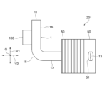
- FIG. 8 is a plan view showing an overview of the heat sink according to the first embodiment of the present invention.
- FIG. 9 is a side view showing an overview of the heat sink according to the first embodiment of the present invention.
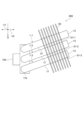
- the heat sink 201 according to the first embodiment of the present invention uses the heat pipe 1 according to the first embodiment, i.e., an L-shaped heat pipe, as the heat transport section.
- the longitudinal shape of the heat pipe 1 is approximately L-shaped, with one bent section 15 and two straight sections connected via the bent section 15.
- the two straight sections are straight section 16 with one end 11 and straight section 17 with the other end 13.
- the straight section 16 having one end 11 is thermally connected to the heating element 100 and functions as an evaporation section (heat receiving section).
- the straight section 17 having the other end 13 is thermally connected to a plurality of heat dissipation fins 50, 50, 50... as heat exchange means and functions as a condensation section (heat dissipation section).
- the heat dissipation fins 50 are thin plate-like metal members.
- a through hole 51 is formed in the thickness direction of the heat dissipation fin 50, and the straight section 17 of the heat pipe 1 is inserted into the through hole 51, thereby thermally connecting the heat dissipation fin 50 to the straight section 17.
- the straight portion 16 to which the heating element 100 is thermally connected extends in a first orthogonal direction V1 (front-to-back direction) that is a first orthogonal direction to the direction of gravity G.
- the straight portion 17 to which the heat dissipation fins 50 are thermally connected extends in a direction that rises at a predetermined angle (e.g., about 10°) with respect to a second orthogonal direction V2 (left-to-right direction) that is orthogonal to the direction of gravity G and the first orthogonal direction V1.
- the bent portion 15 is in the same position in the direction of gravity G as the straight portion 16 to which the heating element 100 is thermally connected.
- the heat sink 201 does not include a heat receiving block, but as with the heat sink according to the sixth embodiment described below, a heat receiving block extending along the direction of gravity G may be thermally connected to the area of the straight section 16 having one end 11 of the heat pipe 1.
- a heat receiving block extending along the direction of gravity G may be thermally connected to the area of the straight section 16 having one end 11 of the heat pipe 1.
- the heating element 100 is thermally connected to the outer surface of the heat receiving block, and heat from the heating element 100 is transferred to the straight section 16 of the heat pipe 1 via the heat receiving block.
- FIG. 10 is a plan view showing an overview of the heat sink according to the second embodiment of the present invention.
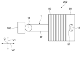
- FIG. 11 is a side view showing an overview of the heat sink according to the second embodiment of the present invention.
- the heat sink 202 according to the second embodiment of the present invention uses the heat pipe 1 according to the first embodiment, i.e., an L-shaped heat pipe, as the heat transport section.
- the longitudinal shape of the heat pipe 1 is approximately L-shaped, with one bent section 15 and two straight sections connected via the bent section 15.
- the two straight sections are straight section 16 with one end 11 and straight section 17 with the other end 13.
- the straight section 16 having one end 11 is thermally connected to the heating element 100 and functions as an evaporation section (heat receiving section).
- the straight section 17 having the other end 13 is thermally connected to a plurality of heat dissipation fins 50, 50, 50... as heat exchange means and functions as a condensation section (heat dissipation section).
- the heat dissipation fins 50 are thin plate-like metal members.
- a through hole 51 is formed in the thickness direction of the heat dissipation fin 50, and the straight section 17 of the heat pipe 1 is inserted into the through hole 51, thereby thermally connecting the heat dissipation fin 50 to the straight section 17.
- the straight portion 16 to which the heating element 100 is thermally connected extends in the direction of gravity G.
- the straight portion 17 to which the heat dissipation fins 50 are thermally connected extends in a direction that rises at a predetermined angle (e.g., about 10°) with respect to the second orthogonal direction V2, which is orthogonal to the direction of gravity G and the first orthogonal direction V1.
- the bent portion 15 is located below the direction of gravity G with respect to the straight portion 16 to which the heating element 100 is thermally connected.
- the heat receiving block is omitted from the heat sink 202, but as with the heat sink according to the sixth embodiment described below, a heat receiving block extending along the direction of gravity G may be thermally connected to the region of the straight section 16 having one end 11 of the heat pipe 1.
- the method of thermally connecting the heat receiving block to the heat pipe 1 is not particularly limited, and an example is a method in which the straight section 16 of the heat pipe 1 is fitted into a recess formed in the heat receiving block and soldered.
- the heating element 100 is thermally connected to the outer surface of the heat pipe 1, and heat from the heating element 100 is transferred to the straight section 16 of the heat pipe 1 via the heat receiving block.
- FIG. 12 is a plan view showing an overview of the heat sink according to the third embodiment of the present invention.
- FIG. 13 is a side view showing an overview of the heat sink according to the third embodiment of the present invention.
- the heat sink 203 according to the third embodiment of the present invention uses the heat pipe 1 according to the first embodiment, i.e., an L-shaped heat pipe, as the heat transport section.
- the longitudinal shape of the heat pipe 1 is approximately L-shaped, with one bent section 15 and two straight sections connected via the bent section 15.
- the two straight sections are straight section 16 with one end 11 and straight section 17 with the other end 13.
- the straight section 16 having one end 11 is thermally connected to the heating element 100 and functions as an evaporation section (heat receiving section).
- the straight section 17 having the other end 13 is thermally connected to a plurality of heat dissipation fins 50, 50, 50... as heat exchange means and functions as a condensation section (heat dissipation section).
- the heat dissipation fins 50 are thin plate-like metal members.
- a through hole 51 is formed in the thickness direction of the heat dissipation fin 50, and the straight section 17 of the heat pipe 1 is inserted into the through hole 51, thereby thermally connecting the heat dissipation fin 50 to the straight section 17.
- the straight portion 16 to which the heating element 100 is thermally connected extends in the direction of gravity G.
- the straight portion 17 to which the heat dissipation fins 50 are thermally connected extends in a direction that rises at a predetermined angle (e.g., about 10°) with respect to the second orthogonal direction V2, which is orthogonal to the direction of gravity G and the first orthogonal direction V1.
- the bent portion 15 is located above the direction of gravity G with respect to the straight portion 16 to which the heating element 100 is thermally connected.
- the heat receiving block is omitted from the heat sink 203, but as with the heat sink according to the sixth embodiment described below, a heat receiving block extending along the direction of gravity G may be thermally connected to the region of the straight section 16 having one end 11 of the heat pipe 1.
- a heat receiving block extending along the direction of gravity G may be thermally connected to the region of the straight section 16 having one end 11 of the heat pipe 1.
- the heating element 100 is thermally connected to the outer surface of the heat receiving block, and heat from the heating element 100 is transferred to the straight section 16 of the heat pipe 1 via the heat receiving block.
- FIG. 14 is a plan view showing an overview of the heat sink according to the fourth embodiment of the present invention.
- FIG. 15 is a side view showing an overview of the heat sink according to the fourth embodiment of the present invention.
- the heat sink 204 uses the heat pipe 2 according to the second embodiment, i.e., a substantially U-shaped heat pipe, as the heat transport section.
- the longitudinal shape of the heat pipe 2 is arranged so that a straight section 16 having one end 11 faces a straight section 17 having the other end 13, and a straight central section 19 connects the straight section 16 having one end 11 with the straight section 17 having the other end 13.
- a bent section 15-1 is provided between the straight section 16 having one end 11 and the central section 19, and a bent section 15-2 is provided between the straight section 17 having the other end 13 and the central section 19.
- the heating element 100 is thermally connected to the central portion 19, and functions as an evaporation portion (heat receiving portion).
- a plurality of heat dissipation fins 50, 50, 50... are thermally connected to the straight portion 16 having one end 11 and the straight portion 17 having the other end 13 as heat exchange means, and function as a condensation portion (heat dissipation portion).
- the heat dissipation fin 50 is a thin plate-like metal member.
- Two through holes 51 are formed in the thickness direction of the heat dissipation fin 50, and the straight portion 16 of the heat pipe 2 is inserted into one through hole 51, and the straight portion 17 of the heat pipe 2 is inserted into the other through hole 51, so that the heat dissipation fin 50 is thermally connected to the straight portion 16 and the straight portion 17.
- the central portion 19 to which the heating element 100 is thermally connected extends in a first orthogonal direction V1 (front-to-back direction) that is a first orthogonal direction to the direction of gravity G.
- the straight portions 16 and 17 to which the heat dissipation fins 50 are thermally connected extend in a direction that rises at a predetermined angle (e.g., about 10°) with respect to a second orthogonal direction V2 (left-to-right direction) that is orthogonal to the direction of gravity G and the first orthogonal direction V1.
- the bent portions 15-1 and 15-2 are in the same position in the direction of gravity G as the central portion 19 to which the heating element 100 is thermally connected.
- the heat receiving block is omitted from the heat sink 204, but as with the heat sink according to the sixth embodiment described below, a heat receiving block extending along the direction of gravity G may be thermally connected to the linear central portion 19 area of the heat pipe 2.
- a heat receiving block extending along the direction of gravity G may be thermally connected to the linear central portion 19 area of the heat pipe 2.
- the heating element 100 is thermally connected to the outer surface of the heat receiving block, and heat from the heating element 100 is transferred to the central portion 19 of the heat pipe 2 via the heat receiving block.
- FIG. 16 is a plan view showing an overview of the heat sink according to the fifth embodiment of the present invention.
- FIG. 17 is a side view showing an overview of the heat sink according to the fifth embodiment of the present invention.
- the heat sink 205 according to the fifth embodiment of the present invention uses the heat pipe 3 according to the third embodiment, i.e., a vapor chamber that is a flat heat pipe, as the heat transport section.
- a heating element 100 is thermally connected to the center of the outer surface of one main surface 44 of the flat container 40, and the center of the outer surface of one main surface 44 functions as a heat receiving portion.
- a plurality of heat dissipation fins 50, 50, 50... are thermally connected to the other main surface 45 opposite the one main surface 44.
- the heat dissipation fins 50 are thin plate-shaped metal members. The heat dissipation fins 50 are erected on the other main surface 45, and are therefore thermally connected to the other main surface 45.
- one main surface 44 and the other main surface 45 extend in a direction perpendicular to the direction of gravity G.
- FIG. 18 is a plan view showing an overview of the heat sink according to the sixth embodiment of the present invention.
- FIG. 19 is a side view showing an overview of the heat sink according to the sixth embodiment of the present invention.
- the heat sink 206 of the sixth embodiment uses the heat pipe 1 of the first embodiment, i.e., an L-shaped heat pipe, as the heat transport section.
- the longitudinal shape of the heat pipe 1 is approximately L-shaped, with one bent section 15 and two straight sections connected via the bent section 15.
- the two straight sections are straight section 16 with one end 11 and straight section 17 with the other end 13.
- a heat receiving block 110 is further thermally connected to the area of the straight section 16 having one end 11 of the container 10.
- the method of thermally connecting the heat receiving block 110 to the container 10 is not particularly limited, and an example is a method in which the straight section 16 of the container 10 is fitted into a recess formed in the heat receiving block 110 and soldered.
- the heating element 100 is thermally connected to the outer surface of the heat receiving block 110, and the heat of the heating element 100 is transferred to the straight section 16 of the container 10 via the heat receiving block 110.
- the straight section 16 having one end 11 is thermally connected to the heating element 100 via the heat receiving block 110, and functions as an evaporation section (heat receiving section).
- the straight section 17 having the other end 13 is thermally connected to a plurality of heat dissipation fins 50, 50, 50... as heat exchange means, and functions as a condensation section (heat dissipation section).
- the heat dissipation fins 50 are thin plate-shaped metal members. Through holes 51 are formed in the thickness direction of the heat dissipation fins 50, and the straight section 17 of the heat pipe 1 is inserted into the through holes 51, so that the heat dissipation fins 50 are thermally connected to the straight section 17.
- the straight portion 16 to which the heating element 100 is thermally connected via the heat receiving block 110 extends in a first orthogonal direction V1 (front-to-back direction) that is a first orthogonal direction to the direction of gravity G.
- the straight portion 17 to which the heat dissipation fins 50 are thermally connected extends in a direction that rises at a predetermined angle (e.g., about 10°) with respect to a second orthogonal direction V2 (left-to-right direction) that is orthogonal to the direction of gravity G and the first orthogonal direction V1.
- the bent portion 15 is in the same position in the direction of gravity G as the straight portion 16 to which the heating element 100 is thermally connected via the heat receiving block 110.
- the temperature of the environment in which the heat sinks in each of the above embodiments are used can be, for example, between -50°C and 90°C.
- the heat sinks 201-206 have heat pipes 1-3 and heat dissipation fins 50 that are thermally connected to a portion of the containers 10, 40 of the heat pipes 1-3, so that the working fluid 30 in the heat pipes 1-3 can be prevented from freezing even in a low-temperature operating environment, and excellent flow characteristics of the working fluid 30 can be exhibited, and space can be saved and the freedom of installation can be improved.
- FIG. 20 is a plan view showing an overview of the heat sink of the seventh embodiment of the present invention.
- FIG. 21 is a side view showing an overview of the heat sink of the seventh embodiment of the present invention.
- the heat sink 207 of the seventh embodiment uses a plurality of heat pipes of the first embodiment, i.e., L-shaped heat pipes (here, three heat pipes: 1-1, 1-2, and 1-3), as the heat transport section.
- the longitudinal shape of the heat pipes 1-1, 1-2, and 1-3 is approximately L-shaped, with one bent section 15 and two straight sections connected via the bent section 15.
- the two straight sections are straight section 16 with one end 11 and straight section 17 with the other end 13.
- a heat receiving block 110 is further thermally connected to the area of the straight section 16 having one end 11 of the container 10 of each of the heat pipes 1-1, 1-2, and 1-3.
- the method of thermally connecting the heat receiving block 110 to the container 10 is not particularly limited, and an example is a method of fitting the straight section 16 of the container 10 into a recess formed in the heat receiving block 110 and soldering it.
- the heating elements 100-1 and 100-2 are thermally connected to the outer surface of the heat receiving block 110, and the heat of the heating elements 100-1 and 100-2 is transferred to the straight section 16 of the container 10 of each of the heat pipes 1-1, 1-2, and 1-3 via the heat receiving block 110.
- the straight section 16 which has one end 11, is thermally connected to the heating elements 100-1 and 100-2 via the heat receiving block 110, and functions as an evaporation section (heat receiving section).
- the heat dissipation fin 50 is a thin plate-like metal member.
- Three through holes 51-1, 51-2, 51-3 are formed in the thickness direction of the heat dissipation fin 50, and the straight sections 17 of the heat pipes 1-1, 1-2, 1-3 are inserted into the through holes 51-1, 51-2, 51-3, respectively, so that the plurality of heat dissipation fins 50 are thermally connected to the straight section 17.
- the straight section 16 to which the heating elements 100-1, 100-2 are thermally connected via the heat receiving block 110 extends in a first orthogonal direction V1 (front-back direction) that is a first orthogonal direction to the direction of gravity G.
- the straight section 17 to which the heat dissipation fins 50 are thermally connected extends in a direction that rises a predetermined angle ⁇ with respect to a second orthogonal direction V2 (left-right direction) that is orthogonal to the direction of gravity G and the first orthogonal direction V1.
- the bent section 15 is in the same position in the direction of gravity G as the straight section 16 to which the heating element 100 is thermally connected via the heat receiving block 110.
- the working fluids of the heat pipes 1-1, 1-2, and 1-3 may all be the same, but different working fluids may be used for the heat pipes 1-1, 1-2, and 1-3.
- the working fluid of the heat pipe 1-2 may be water
- the working fluids of the heat pipes 1-1 and 1-3 on both sides may be something other than water (for example, a working fluid containing hydrofluoroolefin). This is because, in terms of the magnitude relationship of latent heat, when other conditions are the same, a heat pipe whose working fluid is water can transport a greater amount of heat than a heat pipe whose working fluid is something other than water.
- the low-temperature start-up of heat pipe 1-2 whose working fluid is water can be improved by utilizing heat transport by heat pipes 1-1 and 1-3 and heat from the heating element before the temperature of the heating element becomes too high at low temperatures.
- the above describes a heat sink configuration in which a heat pipe whose working fluid is water is placed between two heat pipes whose working fluid contains hydrofluoroolefin, but this configuration can be modified as appropriate depending on the environment in which the heat sink is installed.
- the working fluid of heat pipes 1-1 and 1-2 may contain hydrofluoroolefin, and the working fluid of heat pipe 1-3 may be water.
- air flowing from the upstream side i.e., the upper side of FIG. 21
- the two heat pipes 1-1 and 1-2 is heated by the two heat pipes 1-1 and 1-2, and then flows around heat pipe 1-3 whose working fluid is water and located downstream (i.e., the lower side of FIG. 20), thereby improving the low-temperature start-up performance of heat pipe 1-3.
- a heating element 100-1 is placed directly below one heat pipe 1-1, the heat input will be concentrated on the single heat pipe 1-1, increasing the possibility of exceeding the heat transport capacity of the heat pipe and causing it to dry out. Therefore, it is preferable to place multiple (here, two) heat pipes 1-2 and 1-3 around the heating element 100-2. In this way, the heat input can be distributed among multiple heat pipes, making it possible to prevent the heat pipes from drying out.
- the angle ⁇ shown in FIG. 21 is preferably between 5° and 12°, and is particularly preferably 7°. If you wish to improve the low-temperature start-up performance of a heat pipe whose working fluid is water, it is advisable to set this angle ⁇ to a large value. This is because the water reflux speed within the container increases, shortening the cooling time until it returns to the heat receiving section, making the water less likely to freeze within the container.
- the working fluid of each heat pipe can be selected appropriately according to the design policy. For example, in a design policy to lower the temperature of the heat generating part by lowering the thermal resistance, a heat pipe using a working fluid containing a hydrofluoroolefin with low thermal resistance may be arranged near the heat generating part, and the insufficient amount of heat transport may be compensated for by a heat pipe whose working fluid is water. In addition, in a design policy to reduce costs, the arrangement of heat pipes whose working fluid is water may be prioritized, and the number of heat pipes whose working fluid is containing hydrofluoroolefin may be reduced.
- FIG. 22 is a side view showing an overview of a heat sink according to the eighth embodiment of the present invention. Components similar to those shown in the seventh embodiment are given the same reference numerals and will not be described.
- the distance between adjacent heat pipes 1-1, 1-2, and 1-3 is set even smaller than the distance between heat pipes 1-1, 1-2, and 1-3 in the heat sink 207 of the seventh embodiment.
- this distance may be shorter than the diameter of each heat pipe.
- FIG. 23 is a side view showing an overview of a heat sink according to the ninth embodiment of the present invention. Components similar to those shown in the seventh and eighth embodiments are given the same reference numerals and will not be described.
- the heat sink 209 according to the ninth embodiment is different from the heat sink 207 according to the seventh embodiment in that the spacing between the heat dissipation fins 50 is different between the base side 50-1 of the heat pipe and the tip side 50-2 of the heat pipe, as shown in FIG. 23. In other words, the number of fins on the tip side 50-2 of the heat pipe is reduced compared to the number of fins on the base side 50-1 of the heat pipe.
- the working fluid is water
- there is a problem that the water is likely to freeze before the steam that reaches the condensation section on the end 13 side in the container is condensed and returns to the heat receiving section.
- the fins on the tip side 50-2 of the heat pipe in the heat sink 209 dissipate less heat than the fins on the base side 50-1, and therefore the temperature of the water, which is the working fluid, is more likely to rise, and the start-up performance of this heat pipe can be improved. Furthermore, the distance that the water travels in the container is shortened, so the maximum heat transport amount also increases. However, the heat dissipation performance from the fins is reduced.
- the longitudinal shape of the container which is a tube
- the longitudinal shape of the container which is a tube
- the longitudinal shape of the container may be linear without a bent portion.
- the amount of the working fluid containing hydrofluoroolefin to be enclosed is not particularly limited, but in order to impart excellent heat transport properties to the heat pipe, it is preferable that the amount of the working fluid enclosed has a cross-sectional area of 40% or more of the cross-sectional area of the cavity, which is the internal space of the heat pipe, in at least one cross section perpendicular to the longitudinal direction of the heat pipe when the longitudinal direction of the heat pipe is perpendicular to the direction of gravity, and in order to further improve the heat transport properties of the heat pipe, it is more preferable that the amount of the working fluid enclosed has a cross-sectional area of 50% or more of the cross-sectional area of the cavity, and it is particularly preferable that the amount of the working fluid enclosed has a cross-sectional area of 55% or more of the cross-sectional area of the cavity.
- the shape of the container in a plan view is rectangular, but the shape of the container in a plan view is not particularly limited, and may instead be triangular, a polygonal shape with pentagons or more, circular, a shape with a cutout, a shape with a bent portion, etc.
- the maximum heat transport amount was measured by thermally connecting the heating element to the heat pipe via a heat receiving block, attaching a heat dissipation fin to the other end of the heat pipe, inputting a constant amount of heat, measuring the temperature of the heat source while increasing the amount of heat input, measuring the amount of heat input at which the thermal resistance, expressed by the formula below, began to increase, and determining the maximum heat input amount within the range where the thermal resistance did not increase.
- Thermal resistance [°C/W] (temperature of heat source - temperature of outside air around heat pipe) [°C]/(amount of heat input) [W]
- amount of working fluid refers to the area ratio (%) of the working fluid to the cross-sectional area of the internal space of the straight section in a cross section perpendicular to the longitudinal direction of the straight section functioning as the evaporation section (heat receiving section) of the container when the longitudinal direction of the straight section is perpendicular to the direction of gravity.
- length (x) refers to the length of the straight section that functions as the evaporation section (heat receiving section) among the multiple straight sections
- length (z) refers to the length of the straight section that functions as the condensation section (heat dissipation section) among the multiple straight sections
- N/A refers to no match.
- thickness (y) refers to the thickness of the internal space of the vapor channel container.
- condensation section leading angle refers to the angle of the condensation section that extends upward in the direction of gravity with respect to a virtual line that extends perpendicular to the direction of gravity
- number of the "heat sink to be evaluated” refers to the code of the heat sink according to each of the above-mentioned embodiments.
- Examples 1 to 17 had good heat transport properties, with a maximum heat transport capacity of 30 W or more when the condenser was installed in a position extending upward in the direction of gravity, even when a heat pipe containing a working fluid containing hydrofluoroolefin was used. Therefore, it was found that Examples 1 to 17 have improved freedom in installing the heat pipe and heat sink, have good heat transport properties, and can prevent freezing of the working fluid even in low-temperature operating environments while reducing the burden on the environment and exhibit excellent flow properties.
- the maximum heat transport amount is further improved by providing fine grooves, which are wick structures, on the inner surface of the heat pipe.
- Examples 13 to 15 in which the width (average width) of the fine grooves is 0.3 mm and there are a large number of fine grooves, have a further improved maximum heat transport amount.
- the maximum heat transport amount is further improved with trans-1,3,3,3-tetrafluoroprop-1-ene (HFO-1234ze(E)).
- Example 1 in which the amount of working fluid is 60% has a further improved maximum heat transport amount compared to Example 12, in which the amount of working fluid is 40%.
- the maximum heat transport amount of the heat pipe is further improved.
- the reason why the maximum heat transport amount of Example 4 is improved over the maximum heat transport amount of Example 3 is that in heat sink 202, which is the heat sink evaluated in Example 3, the part where the heating element is thermally connected is located above the part where the heat dissipation fins are thermally connected in the direction of gravity, compared to heat sink 203, which is the heat sink evaluated in Example 4. In other words, this is because the heat sink evaluated in Example 3 is used in a top heat mode.
- the heat pipe and heat sink of the present invention reduce the burden on the environment, prevent freezing of the working fluid, and exhibit excellent flow characteristics even in low-temperature environments. Therefore, they can be used in fields such as cooling electronic components such as semiconductor elements mounted in electrical and electronic devices such as notebook computers, servers, and data centers, and electronic components such as power semiconductors mounted in power control devices for trains, etc.
Landscapes
- Engineering & Computer Science (AREA)
- Physics & Mathematics (AREA)
- Thermal Sciences (AREA)
- Mechanical Engineering (AREA)
- General Engineering & Computer Science (AREA)
- Life Sciences & Earth Sciences (AREA)
- Sustainable Development (AREA)
- Geometry (AREA)
- Cooling Or The Like Of Semiconductors Or Solid State Devices (AREA)
- Cooling Or The Like Of Electrical Apparatus (AREA)
Priority Applications (3)
| Application Number | Priority Date | Filing Date | Title |
|---|---|---|---|
| KR1020257027477A KR20250153781A (ko) | 2023-03-06 | 2024-03-05 | 히트 파이프 및 히트 싱크 |
| JP2025505334A JPWO2024185753A1 (https=) | 2023-03-06 | 2024-03-05 | |
| US19/316,897 US20260002738A1 (en) | 2023-03-06 | 2025-09-02 | Heat pipe and heat sink |
Applications Claiming Priority (2)
| Application Number | Priority Date | Filing Date | Title |
|---|---|---|---|
| JP2023033683 | 2023-03-06 | ||
| JP2023-033683 | 2023-03-06 |
Related Child Applications (1)
| Application Number | Title | Priority Date | Filing Date |
|---|---|---|---|
| US19/316,897 Continuation US20260002738A1 (en) | 2023-03-06 | 2025-09-02 | Heat pipe and heat sink |
Publications (1)
| Publication Number | Publication Date |
|---|---|
| WO2024185753A1 true WO2024185753A1 (ja) | 2024-09-12 |
Family
ID=92675191
Family Applications (1)
| Application Number | Title | Priority Date | Filing Date |
|---|---|---|---|
| PCT/JP2024/008177 Ceased WO2024185753A1 (ja) | 2023-03-06 | 2024-03-05 | ヒートパイプ及びヒートシンク |
Country Status (4)
| Country | Link |
|---|---|
| US (1) | US20260002738A1 (https=) |
| JP (1) | JPWO2024185753A1 (https=) |
| KR (1) | KR20250153781A (https=) |
| WO (1) | WO2024185753A1 (https=) |
Citations (9)
| Publication number | Priority date | Publication date | Assignee | Title |
|---|---|---|---|---|
| JPS59140448U (ja) * | 1983-03-10 | 1984-09-19 | 古河電気工業株式会社 | ヒ−トパイプ式放熱器 |
| JPH02229455A (ja) * | 1989-03-02 | 1990-09-12 | Furukawa Electric Co Ltd:The | ヒートパイプ式装置 |
| JP2002139284A (ja) * | 2000-11-02 | 2002-05-17 | Toshiba Transport Eng Inc | 車両用半導体冷却装置 |
| JP2005214565A (ja) * | 2004-01-30 | 2005-08-11 | Sumitomo Light Metal Ind Ltd | ヒートパイプ式ヒートシンク |
| WO2013111815A1 (ja) * | 2012-01-27 | 2013-08-01 | 古河電気工業株式会社 | 熱輸送装置 |
| JP2013249326A (ja) * | 2012-05-30 | 2013-12-12 | Central Glass Co Ltd | フルオロアルケンを含有する熱伝達媒体 |
| JP2021055914A (ja) * | 2019-09-30 | 2021-04-08 | 古河電気工業株式会社 | ヒートパイプ |
| JP2021085609A (ja) * | 2019-11-28 | 2021-06-03 | 株式会社日立製作所 | 移動体用の冷却装置及び電力変換装置 |
| JP2022537644A (ja) * | 2019-05-30 | 2022-08-29 | 浙江省化工研究院有限公司 | 環境に優しいヒートパイプの作業物質 |
-
2024
- 2024-03-05 JP JP2025505334A patent/JPWO2024185753A1/ja active Pending
- 2024-03-05 WO PCT/JP2024/008177 patent/WO2024185753A1/ja not_active Ceased
- 2024-03-05 KR KR1020257027477A patent/KR20250153781A/ko active Pending
-
2025
- 2025-09-02 US US19/316,897 patent/US20260002738A1/en active Pending
Patent Citations (9)
| Publication number | Priority date | Publication date | Assignee | Title |
|---|---|---|---|---|
| JPS59140448U (ja) * | 1983-03-10 | 1984-09-19 | 古河電気工業株式会社 | ヒ−トパイプ式放熱器 |
| JPH02229455A (ja) * | 1989-03-02 | 1990-09-12 | Furukawa Electric Co Ltd:The | ヒートパイプ式装置 |
| JP2002139284A (ja) * | 2000-11-02 | 2002-05-17 | Toshiba Transport Eng Inc | 車両用半導体冷却装置 |
| JP2005214565A (ja) * | 2004-01-30 | 2005-08-11 | Sumitomo Light Metal Ind Ltd | ヒートパイプ式ヒートシンク |
| WO2013111815A1 (ja) * | 2012-01-27 | 2013-08-01 | 古河電気工業株式会社 | 熱輸送装置 |
| JP2013249326A (ja) * | 2012-05-30 | 2013-12-12 | Central Glass Co Ltd | フルオロアルケンを含有する熱伝達媒体 |
| JP2022537644A (ja) * | 2019-05-30 | 2022-08-29 | 浙江省化工研究院有限公司 | 環境に優しいヒートパイプの作業物質 |
| JP2021055914A (ja) * | 2019-09-30 | 2021-04-08 | 古河電気工業株式会社 | ヒートパイプ |
| JP2021085609A (ja) * | 2019-11-28 | 2021-06-03 | 株式会社日立製作所 | 移動体用の冷却装置及び電力変換装置 |
Also Published As
| Publication number | Publication date |
|---|---|
| KR20250153781A (ko) | 2025-10-27 |
| JPWO2024185753A1 (https=) | 2024-09-12 |
| US20260002738A1 (en) | 2026-01-01 |
| TW202438637A (zh) | 2024-10-01 |
Similar Documents
| Publication | Publication Date | Title |
|---|---|---|
| US20180080685A1 (en) | Microelectronics cooling system | |
| CN1902754B (zh) | 带有气泡泵的冷却系统 | |
| JP6560425B1 (ja) | ヒートパイプ | |
| CN102834688B (zh) | 相变冷却器和设有该相变冷却器的电子设备 | |
| US7621316B2 (en) | Heat sink with heat pipes and method for manufacturing the same | |
| US11828539B2 (en) | Heat pipe | |
| US20060196640A1 (en) | Vapor chamber with boiling-enhanced multi-wick structure | |
| US20140165638A1 (en) | Cooling device and electronic device made therewith | |
| WO2014157147A1 (ja) | 冷却装置 | |
| US20100326627A1 (en) | Microelectronics cooling system | |
| JP2008527285A (ja) | 気泡ポンプを有する多方位冷却システム | |
| US20070230128A1 (en) | Cooling apparatus with surface enhancement boiling heat transfer | |
| WO2017115772A1 (ja) | ヒートパイプ | |
| US11369042B2 (en) | Heat exchanger with integrated two-phase heat spreader | |
| US11859912B2 (en) | Microelectronics cooling system | |
| US20080308257A1 (en) | Heat dissipating assembly | |
| WO2024185753A1 (ja) | ヒートパイプ及びヒートシンク | |
| TWI919207B (zh) | 熱管及散熱裝置 | |
| JP5087504B2 (ja) | ヒートパイプ | |
| WO2022185908A1 (ja) | ヒートパイプ | |
| JP7129577B1 (ja) | 熱輸送装置 | |
| TWI858579B (zh) | 散熱器 | |
| JP7704705B2 (ja) | ヒートシンク | |
| JP6197651B2 (ja) | 冷却装置 | |
| JP2024107734A (ja) | ヒートシンク |
Legal Events
| Date | Code | Title | Description |
|---|---|---|---|
| 121 | Ep: the epo has been informed by wipo that ep was designated in this application |
Ref document number: 24767121 Country of ref document: EP Kind code of ref document: A1 |
|
| WWE | Wipo information: entry into national phase |
Ref document number: 2025505334 Country of ref document: JP |
|
| ENP | Entry into the national phase |
Ref document number: 1020257027477 Country of ref document: KR Free format text: ST27 STATUS EVENT CODE: A-0-1-A10-A15-NAP-PA0105 (AS PROVIDED BY THE NATIONAL OFFICE) |
|
| WWE | Wipo information: entry into national phase |
Ref document number: 202517088653 Country of ref document: IN |
|
| NENP | Non-entry into the national phase |
Ref country code: DE |
|
| WWP | Wipo information: published in national office |
Ref document number: 1020257027477 Country of ref document: KR |
|
| WWP | Wipo information: published in national office |
Ref document number: 202517088653 Country of ref document: IN |
|
| 122 | Ep: pct application non-entry in european phase |
Ref document number: 24767121 Country of ref document: EP Kind code of ref document: A1 |