WO2024185530A1 - ガスタービン装置及びガスタービン装置の運転方法 - Google Patents
ガスタービン装置及びガスタービン装置の運転方法 Download PDFInfo
- Publication number
- WO2024185530A1 WO2024185530A1 PCT/JP2024/006485 JP2024006485W WO2024185530A1 WO 2024185530 A1 WO2024185530 A1 WO 2024185530A1 JP 2024006485 W JP2024006485 W JP 2024006485W WO 2024185530 A1 WO2024185530 A1 WO 2024185530A1
- Authority
- WO
- WIPO (PCT)
- Prior art keywords
- air
- gas turbine
- purge air
- gas
- oil nozzle
- Prior art date
- Legal status (The legal status is an assumption and is not a legal conclusion. Google has not performed a legal analysis and makes no representation as to the accuracy of the status listed.)
- Ceased
Links
Images



Classifications
-
- F—MECHANICAL ENGINEERING; LIGHTING; HEATING; WEAPONS; BLASTING
- F02—COMBUSTION ENGINES; HOT-GAS OR COMBUSTION-PRODUCT ENGINE PLANTS
- F02C—GAS-TURBINE PLANTS; AIR INTAKES FOR JET-PROPULSION PLANTS; CONTROLLING FUEL SUPPLY IN AIR-BREATHING JET-PROPULSION PLANTS
- F02C7/00—Features, components parts, details or accessories, not provided for in, or of interest apart form groups F02C1/00 - F02C6/00; Air intakes for jet-propulsion plants
- F02C7/22—Fuel supply systems
- F02C7/232—Fuel valves; Draining valves or systems
-
- F—MECHANICAL ENGINEERING; LIGHTING; HEATING; WEAPONS; BLASTING
- F02—COMBUSTION ENGINES; HOT-GAS OR COMBUSTION-PRODUCT ENGINE PLANTS
- F02C—GAS-TURBINE PLANTS; AIR INTAKES FOR JET-PROPULSION PLANTS; CONTROLLING FUEL SUPPLY IN AIR-BREATHING JET-PROPULSION PLANTS
- F02C7/00—Features, components parts, details or accessories, not provided for in, or of interest apart form groups F02C1/00 - F02C6/00; Air intakes for jet-propulsion plants
- F02C7/12—Cooling of plants
-
- F—MECHANICAL ENGINEERING; LIGHTING; HEATING; WEAPONS; BLASTING
- F02—COMBUSTION ENGINES; HOT-GAS OR COMBUSTION-PRODUCT ENGINE PLANTS
- F02C—GAS-TURBINE PLANTS; AIR INTAKES FOR JET-PROPULSION PLANTS; CONTROLLING FUEL SUPPLY IN AIR-BREATHING JET-PROPULSION PLANTS
- F02C6/00—Plural gas-turbine plants; Combinations of gas-turbine plants with other apparatus; Adaptations of gas-turbine plants for special use
- F02C6/04—Gas-turbine plants providing heated or pressurised working fluid for other apparatus, e.g. without mechanical power output
- F02C6/06—Gas-turbine plants providing heated or pressurised working fluid for other apparatus, e.g. without mechanical power output providing compressed gas
- F02C6/08—Gas-turbine plants providing heated or pressurised working fluid for other apparatus, e.g. without mechanical power output providing compressed gas the gas being bled from the gas-turbine compressor
-
- F—MECHANICAL ENGINEERING; LIGHTING; HEATING; WEAPONS; BLASTING
- F02—COMBUSTION ENGINES; HOT-GAS OR COMBUSTION-PRODUCT ENGINE PLANTS
- F02C—GAS-TURBINE PLANTS; AIR INTAKES FOR JET-PROPULSION PLANTS; CONTROLLING FUEL SUPPLY IN AIR-BREATHING JET-PROPULSION PLANTS
- F02C7/00—Features, components parts, details or accessories, not provided for in, or of interest apart form groups F02C1/00 - F02C6/00; Air intakes for jet-propulsion plants
- F02C7/22—Fuel supply systems
-
- F—MECHANICAL ENGINEERING; LIGHTING; HEATING; WEAPONS; BLASTING
- F02—COMBUSTION ENGINES; HOT-GAS OR COMBUSTION-PRODUCT ENGINE PLANTS
- F02C—GAS-TURBINE PLANTS; AIR INTAKES FOR JET-PROPULSION PLANTS; CONTROLLING FUEL SUPPLY IN AIR-BREATHING JET-PROPULSION PLANTS
- F02C9/00—Controlling gas-turbine plants; Controlling fuel supply in air- breathing jet-propulsion plants
- F02C9/16—Control of working fluid flow
-
- F—MECHANICAL ENGINEERING; LIGHTING; HEATING; WEAPONS; BLASTING
- F05—INDEXING SCHEMES RELATING TO ENGINES OR PUMPS IN VARIOUS SUBCLASSES OF CLASSES F01-F04
- F05D—INDEXING SCHEME FOR ASPECTS RELATING TO NON-POSITIVE-DISPLACEMENT MACHINES OR ENGINES, GAS-TURBINES OR JET-PROPULSION PLANTS
- F05D2220/00—Application
- F05D2220/30—Application in turbines
- F05D2220/32—Application in turbines in gas turbines
-
- F—MECHANICAL ENGINEERING; LIGHTING; HEATING; WEAPONS; BLASTING
- F05—INDEXING SCHEMES RELATING TO ENGINES OR PUMPS IN VARIOUS SUBCLASSES OF CLASSES F01-F04
- F05D—INDEXING SCHEME FOR ASPECTS RELATING TO NON-POSITIVE-DISPLACEMENT MACHINES OR ENGINES, GAS-TURBINES OR JET-PROPULSION PLANTS
- F05D2240/00—Components
- F05D2240/35—Combustors or associated equipment
-
- F—MECHANICAL ENGINEERING; LIGHTING; HEATING; WEAPONS; BLASTING
- F05—INDEXING SCHEMES RELATING TO ENGINES OR PUMPS IN VARIOUS SUBCLASSES OF CLASSES F01-F04
- F05D—INDEXING SCHEME FOR ASPECTS RELATING TO NON-POSITIVE-DISPLACEMENT MACHINES OR ENGINES, GAS-TURBINES OR JET-PROPULSION PLANTS
- F05D2260/00—Function
- F05D2260/60—Fluid transfer
- F05D2260/607—Preventing clogging or obstruction of flow paths by dirt, dust, or foreign particles
Definitions
- This disclosure relates to a gas turbine device and a method for operating the gas turbine device.
- Patent Document 1 describes a gas turbine equipped with a dual-fuel combustor that selectively uses fuel gas and fuel oil as fuel for combustion, in which sweep air such as compressed air guided from the gas turbine casing is supplied to a pilot nozzle (fuel gas injection nozzle) that does not inject fuel gas as fuel during oil-fired operation to prevent the pilot nozzle from burning.
- sweep air such as compressed air guided from the gas turbine casing
- pilot nozzle fuel gas injection nozzle
- purge air is sometimes supplied to the oil nozzle to prevent burnout due to the intake of combustion gas into the nozzle for injecting oil fuel (hereinafter referred to as the oil nozzle) when oil fuel is not being used, and to remove oil remaining in the oil nozzle when the supply of oil fuel is stopped.
- oil fuel hereinafter referred to as the oil nozzle
- purge air is required to remove the oil remaining in the oil nozzle
- high-pressure air compressed by a compressor separate from the gas turbine compressor (the compressor that generates the compressed air supplied to the combustor) has conventionally been used as this purge air.
- a positive displacement compressor with a high compression ratio is usually used as the compressor for generating this high-pressure purge air.
- At least one embodiment of the present invention aims to provide a gas turbine apparatus and an operating method for the gas turbine apparatus that can effectively suppress damage to gas turbine components while reducing maintenance costs.
- a gas turbine apparatus includes: a combustor casing to which compressed air from a gas turbine compressor is guided; a combustor provided in the combustor casing, the combustor including a gas nozzle for injecting gas fuel and an oil nozzle for ejecting oil fuel; a first purge air line configured to supply first air derived from bleed air from the combustor casing to the oil nozzle; a second purge air line configured to supply second air compressed by an external compressor separate from the gas turbine compressor to the oil nozzle; The first air from the first purge air line and the second air from the second purge air line can be selectively supplied as purge air to the oil nozzle.
- a method for operating a gas turbine apparatus includes: a combustor casing to which air from a gas turbine compressor is guided; a combustor provided in the combustor casing, the combustor including a gas nozzle for injecting gas fuel and an oil nozzle for ejecting oil fuel; a first purge air line configured to supply first air derived from bleed air from the combustor casing to the oil nozzle; a second purge air line configured to supply second air compressed by an external compressor separate from the gas turbine compressor to the oil nozzle;
- a method of operating a gas turbine apparatus comprising: The method includes selectively supplying the first air from the first purge air line and the second air from the second purge air line as purge air to the oil nozzle.
- At least one embodiment of the present invention provides a gas turbine apparatus and a method for operating the gas turbine apparatus that can effectively suppress damage to gas turbine components while reducing maintenance costs.
- FIG. 1 is a schematic configuration diagram of a gas turbine device according to an embodiment.
- 2 is a schematic cross-sectional view of a combustor 4 of the gas turbine apparatus 1 shown in FIG. 1 .
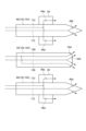
- FIG. 1 is a schematic diagram of a fuel nozzle for a gas turbine system according to an embodiment.
- 1 is a schematic diagram showing an overall configuration of a gas turbine device 1 according to an embodiment.
- Fig. 1 is a schematic configuration diagram of a gas turbine system according to one embodiment.
- the gas turbine system 1 includes a gas turbine compressor 2 for generating compressed air, a combustor 4 for generating combustion gas using the compressed air and fuel, and a turbine 6 configured to be rotationally driven by the combustion gas.
- a generator (not shown) is connected to the turbine 6.
- the gas turbine compressor 2 includes a number of stator vanes 16 fixed to the compressor casing 10, and a number of rotor blades 18 attached to the rotor 8 so as to be arranged alternately with respect to the stator vanes 16. Air taken in from an air intake 12 is sent to the gas turbine compressor 2, and this air is compressed as it passes through the number of stator vanes 16 and the number of rotor blades 18, becoming high-temperature, high-pressure compressed air.
- the combustor 4 is supplied with fuel and compressed air generated by the gas turbine compressor 2, and the fuel is combusted in the combustor 4 to generate combustion gas, which is the working fluid for the turbine 6.
- the gas turbine device 1 has multiple combustors 4 arranged in the circumferential direction around the rotor 8 (rotor axis O) inside the combustor casing 20.
- the turbine 6 has a combustion gas passage 28 formed by the turbine casing 22, and includes a number of stator vanes 24 and rotor blades 26 provided in the combustion gas passage 28.
- the stator vanes 24 and rotor blades 26 of the turbine 6 are provided downstream of the combustor 4 with respect to the flow of combustion gas.
- the stator vanes 24 are fixed to the turbine casing 22 side, and the number of stator vanes 24 arranged along the circumferential direction of the rotor 8 constitute a stator vane row.
- the rotor blades 26 are also implanted in the rotor 8, and the number of rotor blades 26 arranged along the circumferential direction of the rotor 8 constitute a rotor blade row.
- the stator vane row and rotor blade row are arranged alternately in the axial direction of the rotor 8.
- the combustion gas from the combustor 4 flows into the combustion gas passage 28 and passes through a number of stationary vanes 24 and a number of rotor blades 26, driving the rotor 8 to rotate, which drives a generator connected to the rotor 8 to generate electricity. After driving the turbine 6, the combustion gas is exhausted to the outside via the exhaust chamber 30.
- FIG 2 is a schematic cross-sectional view of the combustor 4 of the gas turbine device 1 shown in Figure 1.
- each of the combustors 4 (see Figure 1), which are arranged in a plurality of circumferential directions around the rotor 8, includes a combustion liner 50 provided inside the combustor casing 20, a first combustion burner 38 arranged inside the combustion liner 50, and a plurality of second combustion burners 44 arranged to surround the first combustion burner 38.
- the combustion liner 50, the first combustion burner 38, and the second combustion burner 44 are housed in the combustor casing 20.
- the first combustion burner 38 is arranged to extend along the central axis Q of the combustion tube 50, and has a first fuel nozzle 40 for injecting fuel, and a first burner tube 41 arranged to surround the first fuel nozzle 40. Fuel is supplied to the first fuel nozzle 40 via a first fuel port 42.
- the second combustion burner 44 has a second fuel nozzle 46 for injecting fuel and a second burner tube 47 arranged to surround the second fuel nozzle 46. Fuel is supplied to the second fuel nozzle 46 via the second fuel port 43.
- the combustor 4 further includes an outer cylinder 52 provided on the outer periphery of the combustion cylinder 50 inside the combustor casing 20.
- An air passage 54 through which compressed air flows is formed on the outer periphery of the inner cylinder 48 and on the inner periphery of the outer cylinder 52.
- Swirlers 45, 49 are provided around the first fuel nozzle 40 and the second fuel nozzle 46, respectively, and compressed air from the gas turbine compressor 2 (see Figure 1) is supplied into the combustion liner 50 via the swirlers 45, 49.
- a mixture of fuel and air is formed in the combustion tube 50 by the fuel ejected from the fuel nozzles 40, 46 and the compressed air supplied via the air passage 54 and the swirlers 45, 49.
- the mixture that flows into the combustion tube 50 is ignited by an ignition device (not shown) or by a pilot flame and burns, thereby generating combustion gas.
- the combustion gas flows through the combustion tube 50 and is led to the turbine 6 (see Figure 1).
- the above-mentioned first combustion burner 38 may be configured to form a pilot flame. That is, the first fuel nozzle 40 of the first combustion burner 38 may be a pilot nozzle for ejecting pilot fuel to form a pilot flame.
- the gas turbine device 1 is a gas turbine equipped with a dual-fuel combustor 4 capable of selectively using gas fuel and oil fuel as fuel for combustion.
- the dual-fuel combustor 4 includes both a gas nozzle for ejecting gas fuel and an oil nozzle for ejecting oil fuel.
- a single nozzle member may function as both a gas nozzle and an oil nozzle. That is, a single nozzle member may be provided with passages and nozzle holes for gas fuel, and passages and nozzle holes for oil fuel. Alternatively, in a dual-fuel combustor 4, a nozzle member that functions as a gas nozzle and a nozzle member that functions as an oil nozzle may be installed separately.
- FIG. 3 is a schematic diagram of fuel nozzles (first fuel nozzle 40 and second fuel nozzle 46) of a gas turbine apparatus 1 according to one embodiment.
- the fuel nozzles shown in FIG. 3 are fuel nozzles of a dual-fuel combustor 4.
- the first fuel nozzle 40 and the second fuel nozzle 46 shown in FIG. 3 function as a gas nozzle 102 and an oil nozzle 104, respectively.
- the first fuel nozzle 40 shown in FIG. 3 is a gas nozzle 102 having a gas fuel passage 106 and a gas fuel outlet 40a, and an oil nozzle 104 having an oil fuel passage 108 and an oil fuel outlet 40b.
- the second fuel nozzle 46 shown in FIG. 3 is a gas nozzle 102 having a gas fuel passage 110 and a gas fuel outlet 46a, and an oil nozzle 104 having an oil fuel passage 112 and an oil fuel outlet 46b.
- the gas fuel and the oil fuel are supplied from separate fuel ports.
- FIG. 4 is a schematic diagram showing the overall configuration of a gas turbine system 1 according to one embodiment.
- the gas turbine system 1 shown in FIG. 1 includes the gas turbine compressor 2, combustor 4, and turbine 6 described above.
- the combustor 4 is a dual-fuel combustor capable of selectively using gas fuel and oil fuel as fuel for combustion, and includes both a gas nozzle 102 (not shown in FIG. 4) and an oil nozzle 104.
- the gas turbine device 1 shown in FIG. 1 is equipped with a first purge air line 74 and a second purge air line 82 for supplying purge air to the oil nozzle 104 of the combustor 4.
- the oil nozzle 104 to which the purge air is supplied may be the first fuel nozzle 40 described above, or may be the second fuel nozzle 46 described above.
- the first purge air line 74 is configured to supply the first air derived from the bleed air from the combustor casing 20 (i.e., air compressed by the gas turbine compressor 2) to the oil nozzle 104.
- the gas turbine device 1 includes a first bleed line 62 for bleed air from the combustor casing 20 (i.e., air at the outlet of the gas turbine compressor 2) and a second bleed line 60 branching from the first bleed line 62. A portion of the air flowing through the first bleed line 62 is guided to the second bleed line 60.
- the first purge air line 74 is provided so as to branch off from the second bleed line 60, and is adapted to guide air derived from the air (bleed air) flowing through the second bleed line 60.
- the downstream end of the first purge air line 74 is connected to the second purge air line 82.
- the first purge air line 74 may be provided with a filter 80 for removing foreign matter contained in the bleed air from the combustor casing 20.
- the second purge air line 82 is configured to supply the second air compressed by an external compressor 84 separate from the gas turbine compressor 2 to the oil nozzle 104.
- the second purge air line 82 is provided with external compressors 84A and 84B and is connected to the oil nozzle 104.
- the external compressor 84 may include a positive displacement compressor (such as a reciprocating compressor or a rotary compressor such as a screw compressor).
- the second purge air line 82 may be provided with an air receiver 86 capable of storing the air compressed by the external compressor 84.
- the first air from the first purge air line 74 and the second air from the second purge air line 82 can be selectively supplied as purge air to the oil nozzle 104.
- the first purge air line 74 is provided with a first valve 76 capable of switching the supply state of the first air from the first purge air line 74 to the oil nozzle 104
- the second purge air line 82 is provided with a second valve 88 capable of switching the supply state of the second air from the second purge air line 92 to the oil nozzle 104.
- a pressure regulating valve 90 is provided in the second purge air line 82 downstream of the connection point with the first purge air line 74 to regulate the pressure of the purge air supplied to the oil nozzle 104.
- the gas turbine system 1 it is possible to selectively supply the first air derived from the bleed air from the combustor casing 20 and the second air, which is compressed air generated by the external compressor 84, as purge air for suppressing burnout of the oil nozzle 104 or for blowing off and removing the remaining oil in the oil nozzle 104. If oil fuel remains in the oil nozzle 104, there is a possibility that coking may occur, so it is desirable to remove the oil remaining in the oil nozzle 104.
- a positive displacement compressor which has a high compression ratio and is easy to generate high-pressure gas, is usually used as the external compressor 84.
- Positive displacement compressors tend to break down more frequently than turbo compressors, so they require more frequent maintenance, and if they do break down, it becomes necessary to stop the gas turbine in order to prevent the oil nozzle from burning out.
- the first air derived from the bleed air from the combustor casing 20 can be used as purge air for the oil nozzle 104
- the first air can be supplied instead of the second air generated by the external compressor 84, thereby reducing the frequency of use of the external compressor 84 when supplying purge air to the oil nozzle 104.
- the target to which the purge air is supplied from the first purge air line 74 and the second purge air line 82 may be the first fuel nozzle 40 as an oil nozzle 104 that is arranged to extend along the central axis Q of the combustion tube 50 of the combustor 4 (see Figures 2 and 3).
- the target to which the purge air is supplied from the first purge air line 74 and the second purge air line 82 may be an oil nozzle that functions as a pilot nozzle (e.g., the first fuel nozzle 40 described above).
- the first fuel nozzle 40 (e.g., pilot nozzle, etc.) as the oil nozzle 104 arranged to extend along the central axis Q of the combustion tube 50 is located closer to the area where the fuel is burned than a nozzle arranged in the vicinity of the first fuel nozzle 40 (e.g., the second fuel nozzle 46 as the oil nozzle 104), and therefore has a higher risk of being burned due to the intake of high-temperature combustion gas. Therefore, there is a high need to supply high-pressure purge air to the first fuel nozzle 40.
- a nozzle arranged in the vicinity of the first fuel nozzle 40 e.g., the second fuel nozzle 46 as the oil nozzle 104
- the first air derived from the bleed air from the combustor casing 20 and the second air, which is compressed air generated by the external compressor 84, can be selectively supplied as purge air to the oil nozzle 104 to the first fuel nozzle 40 arranged to extend along the central axis Q of the combustion tube 50. Therefore, damage to gas turbine parts can be more effectively suppressed while reducing maintenance costs.
- the gas turbine system 1 includes an bleed compressor 68 for boosting the bleed air from the combustor casing 20.
- the first purge air line 74 is configured to supply the first air generated by compressing the bleed air in the bleed compressor 68 to the oil nozzle 104.
- an bleed compressor 68 is provided in the second bleed line 60 from which the first purge air line 74 branches, upstream of the branch point of the first purge air line 74.
- the air pressurized by this bleed compressor 68 is guided to the first purge air line 74.
- the bleed air from the combustor casing 20 (air compressed by the gas turbine compressor 2) is further pressurized by the bleed compressor 68, so that it is possible to generate first air having an appropriate pressure (higher than the pressure of the combustor casing 20) as purge air for suppressing the intake of combustion gas into the oil nozzle 104. Therefore, when the first air derived from the bleed air from the combustor casing 20 can be used as purge air (for example, when the pressure of the combustor casing 20 is equal to or higher than a predetermined value), the first air can be supplied as purge air, so that the frequency of use of the external compressor 84 when supplying purge air to the oil nozzle 104 can be reduced. Therefore, the frequency of failure of the gas turbine components can be reduced.
- the above-mentioned extraction compressor 68 may be a turbo compressor (e.g., a centrifugal compressor or an axial compressor, etc.).
- a turbo compressor which generally has a lower failure frequency than a positive displacement compressor, is used as the bleed compressor 68. Therefore, when the first air derived from the bleed air from the combustor casing 20 can be used as purge air, the first air compressed by the bleed compressor 68 can be supplied as purge air, thereby effectively reducing the failure frequency of the gas turbine components. Therefore, it is possible to effectively reduce maintenance costs while effectively suppressing damage to gas turbine parts.
- a valve 67 may be provided to adjust the amount of air flowing through the second bleed line 60 or to block the flow of air in the second bleed line 60.
- the first bleed air line 62 is provided with a first bleed air cooler 64.
- the air bled from the combustor casing 20 via the first bleed air line 62 is cooled by the first bleed air cooler 64 and supplied as cooled air to rotating members of the gas turbine device 1 (such as the rotor disk (rotor 8) of the turbine 6 and the rotor blades 26).
- the first bleed air line 62 may be provided with a booster 63 for boosting the pressure of the cooling air.
- the first bleed air cooler 64 may be configured to cool the air in the first bleed air line 62 by heat exchange with the feed water of a steam turbine (not shown) driven by steam generated by utilizing the heat of the exhaust gas from the gas turbine device 1.
- the feed water may be heated by heat exchange with the exhaust gas from the gas turbine device 1 in a boiler (not shown).
- the second bleed line 60 is provided so as to branch off from the first bleed line 62 downstream of the first bleed cooler 64.
- the second bleed line 60 is configured to supply air from the first bleed line 62 as cooling air to stationary components of the gas turbine device 1 (such as the combustor 4, the blade ring of the turbine 6, the stationary vanes 26, etc.).
- the second bleed line 60 may be configured to supply cooling air of higher pressure to the stationary members of the gas turbine unit 1 than the cooling air supplied from the first bleed line 60 to the rotating members. That is, the pressure at the outlet of the bleed compressor 68 in the second bleed line 60 may be higher than the pressure at the outlet of the booster 63 in the first bleed line 62. In this case, higher pressure cooling air can be supplied to the combustor 4 to which high pressure air from the gas turbine compressor 2 is supplied as combustion air, making it easier to properly cool the combustor 4.
- the second bleed line 60 may be provided with a second bleed cooler 66 for further cooling the air from the first bleed line 62.
- the second bleed line 60 may also be provided with a filter 70 for removing foreign matter contained in the cooling air.
- the second bleed cooler 66 may be configured to cool the air in the second bleed line 60, for example, by heat exchange with condensate from a steam turbine (not shown) driven by steam generated using the heat of the exhaust gas from the gas turbine device 1, or with atmospheric air.
- the above-mentioned condensate includes condensed water generated by condensing the steam discharged from the steam turbine in a condenser.
- the first purge air line 74 is provided so as to branch off from the second bleed air line 60 downstream of the second bleed air cooler 66.
- the first purge air line 74 may be provided with a purge air cooler 78 (cooler) for further cooling the air from the second bleed air line 60.
- the purge air cooler 78 may be configured to cool the air in the first purge air line 74, for example, by heat exchange with water at a temperature below room temperature.
- the first purge air line 74 branches off from the second bleed line 60 for supplying the bleed air from the combustor casing 20 to the stationary parts of the combustor 4 etc. as cooling air, so that the air derived from the bleed air guided from the second bleed line 60 to the first purge air line 74 is supplied to the oil nozzle 104 as purge air.
- the second bleed line 60 can be used for both supplying cooling air and supplying purge air to the oil nozzle 104, and the installation area of the equipment can be reduced compared to the case where the bleed air line for purge air is installed separately from the second bleed line 60 for cooling air.
- the gas turbine system 1 includes at least one cooler (e.g., at least one of the first bleed air cooler 64, the second bleed air cooler 66, or the purge air cooler 78 described above) for cooling the first air derived from the bleed air supplied to the oil nozzle 104 from the combustor casing 20 via the first purge air line 74.
- at least one cooler e.g., at least one of the first bleed air cooler 64, the second bleed air cooler 66, or the purge air cooler 78 described above
- the gas turbine system 1 includes a first bleed air cooler 64, a second bleed air cooler 66, and a purge air cooler 78 as the above-mentioned coolers.
- the first purge air line 74 may be provided with a purge air cooler 78 (cooler) for cooling the first air derived from the bleed air.
- the air flowing from the second bleed line 60, through which the cooling air for cooling the combustor 4 flows, into the first purge air line 74 can be further cooled by the purge air cooler 78 provided in the first purge air line 74. Therefore, by supplying the first air thus cooled to the oil nozzle 104 as purge air, it is possible to more effectively prevent the oil nozzle 104 from burning due to the intake of high-temperature combustion gas, etc.
- air from the first bleed line 62 and the second bleed line 60 for supplying cooling air to the gas turbine device 1 is guided to the first purge air line 74, so that the air derived from the bleed can be easily cooled to a temperature suitable for use as purge air to be supplied to the oil nozzle 104 by utilizing the first bleed cooler 64 provided on the first bleed line 62 and the second bleed cooler 66 provided on the second bleed line 60.
- air from the first bleed line 62 and the second bleed line 60 for supplying cooling air to the gas turbine unit 1 is led to the first purge air line 74, so that the air pressurized by the bleed compressor 68 provided in the second bleed line 60 can be used as purge air for the oil nozzle 104 simply by cooling it with the purge air cooler 78.
- downstream end of the first purge air line 74 may be connected to the second purge air line 82 downstream of the external compressor 84 (84A, 84B).
- the downstream end of the first purge air line 74 is connected to the second purge air line 82 downstream of the external compressor 84, so that the second purge air line 82 can be used to selectively supply, as purge air to the oil nozzle 104, the first air derived from the bleed air from the combustor casing 20 and the second air, which is compressed air generated by the external compressor 84.
- the first purge air line 74 to an existing gas turbine device 1 including the second purge air line 82, the gas turbine device 1 according to some embodiments can be obtained relatively easily.
- the gas turbine system 1 may include a control device 100 (control unit) for controlling the opening and closing of the first valve 76 and the second valve 88.
- control device 100 control unit
- the opening and closing of the first valve 76 and the second valve 88 can be controlled by the control device 100 (control unit), and by appropriately controlling the opening and closing of the first valve 76 and the second valve 88 by the control unit, it is possible to selectively supply the first air from the first purge air line 74 and the second air from the second purge air line 82 as purge air to the oil nozzle 104. Therefore, by appropriately switching the supply source of the purge air between the first purge air line 74 and the second purge air line 82 by the control device 100, it is possible to effectively suppress damage to gas turbine components while reducing maintenance costs.
- the control device 100 may be configured to receive a signal indicating the operating state of the gas turbine device 1 from a higher-level control device, for example.
- the control device 100 may be configured to control the opening and closing of the first valve 76 and the second valve 88 based on the signal indicating the operating state of the gas turbine device 1.
- the control device 100 includes a computer equipped with a processor (CPU, etc.), a main memory device (memory device; RAM, etc.), an auxiliary memory device, and an interface.
- the control device 100 receives signals from a higher-level control device and a pressure sensor 98 (described below) via the interface.
- the processor is configured to process the signals received in this manner.
- the processor is also configured to process a program deployed in the main memory device. This realizes the functions of the control device 100.
- a pressure sensor 98 for detecting the pressure of the second purge air line 82 may be provided downstream of the pressure regulating valve 90 in the second purge air line 82.
- a signal indicating the pressure measurement value obtained by the pressure sensor 98 is sent to a control device 100.
- the control device 100 may be configured to adjust the opening of the pressure regulating valve 90 based on the pressure measurement value obtained by the pressure sensor 98 so that purge air of an appropriate pressure is supplied to the oil nozzle 104.
- a method of operating the gas turbine system 1 includes selectively supplying first air (air derived from the bleed air) from the first purge air line 74 and second air (air compressed by the external compressor 84) from the second purge air line 82 as purge air to the oil nozzle 104.
- the first air derived from the bleed air from the combustor casing 20 and the second air, which is compressed air generated by the external compressor 84 can be selectively supplied as purge air for suppressing burnout of the oil nozzle 104 or for blowing off the remaining oil in the oil nozzle 104.
- a volumetric compressor with a high compression ratio is usually used as the external compressor 84.
- the first air derived from the bleed air from the combustor casing 20 can be used as purge air for the oil nozzle 104
- the first air is supplied instead of the second air generated by the external compressor 84, thereby reducing the frequency of use of the external compressor 84 when supplying purge air to the oil nozzle 104. Therefore, the frequency of failure of gas turbine components can be reduced. Therefore, according to the method according to the embodiment described above, damage to gas turbine parts can be effectively suppressed while reducing maintenance costs.
- the first air from the first purge air line 74 is supplied to the oil nozzle 104 as purge air.
- the first air from the first purge air line 74 is supplied to the oil nozzle 104 as purge air during gas firing operation, thereby suppressing damage to the oil nozzle due to the intake of combustion gas during gas firing operation.
- the frequency of use of the external compressor 84 (compressor for generating the second air) during operation of the gas turbine device 1 can be significantly reduced. Therefore, the frequency of failure of the gas turbine components can be reduced. Therefore, according to the above-mentioned method, damage to gas turbine parts can be effectively suppressed while reducing maintenance costs.
- the first air from the first purge air line 74 is supplied to the oil nozzle 104 as purge air at least from the time when the rotation speed of the gas turbine device 1 increases and reaches the rated rotation speed until the combustor 4 is extinguished when the gas turbine device 1 is stopped.
- the proportion of time spent in gas-fired operation is greater than that spent in oil-fired operation.
- the first air from the first purge air line 74 is supplied to the oil nozzle 104 as purge air during most of the gas-fired operation, thereby suppressing damage to the oil nozzle due to the intake of combustion gas during gas-fired operation.
- the second air from the second purge air line 82 as purge air for the oil nozzle 104, so the frequency of use of the external compressor 84 (compressor for generating the second air) during operation of the gas turbine system 1 can be significantly reduced. Therefore, the frequency of failure of gas turbine components can be reduced.
- damage to gas turbine components can be effectively suppressed while reducing maintenance costs.
- the gas turbine device 1 which burns oil fuel injected from the oil nozzle 104, switches from oil-fired operation to the above-mentioned gas-fired operation
- the second air from the second purge air line 82 is supplied to the oil nozzle 104 as purge air.
- the fuel may be switched between gas fuel and oil fuel.
- the operation of the gas turbine device 1 switches from oil-fired operation to gas-fired operation
- the supply of fuel oil to the oil nozzle 104 is stopped, but at this time, a small amount of fuel oil remains in the oil nozzle 104.
- the high-pressure second air compressed by the external compressor 84 is supplied to the oil nozzle 104 as purge air, so that the oil nozzle 104 can be purged with air while the remaining oil in the oil nozzle 104 can be appropriately blown away.
- the supply of second air from the second purge air line 82 to the oil nozzle 104 is stopped, and the supply of first air from the first purge air line 74 to the oil nozzle 104 is started.
- the supply of the second air as purge air to the oil nozzle 104 is stopped, and the supply of the first air to the oil nozzle 104 is started.
- the second air is supplied as purge air, and when this is no longer necessary, the supply of the second air as purge air is stopped and the supply of the first air is started, thereby reducing the frequency of use of the external compressor 84 (compressor for generating the second air) during operation of the gas turbine device 1. Therefore, the frequency of failure of the gas turbine components can be reduced. Therefore, according to the above method, it is possible to effectively suppress damage to gas turbine parts while reducing maintenance costs.
- the second air from the second purge air line 82 is supplied to the oil nozzle 104 as purge air during at least a portion of the period from when the gas turbine device 1 starts oil-fired operation until the gas turbine device 1 is stopped, for example, during the period from when the rotation speed of the gas turbine device 1 drops from the rated rotation speed to zero.
- the high-pressure second air compressed by the external compressor 84 is supplied to the oil nozzle 104 as purge air within the period until the gas turbine device 1 is stopped during oil-fired operation, so that the remaining oil in the oil nozzle 104 can be appropriately blown away while purging the oil nozzle 104 with air.
- This makes it possible to suppress damage to the oil nozzle 104 due to the intake of combustion gas, etc., and to suppress coking of the remaining oil in the oil nozzle 104. Therefore, according to the above-mentioned method, it is possible to effectively suppress damage to gas turbine parts while reducing maintenance costs.
- a gas turbine device (1) includes: a combustor casing (20) to which compressed air from a gas turbine compressor (2) is guided; a combustor (4) provided in the combustor casing, the combustor (4) including a gas nozzle (102) for injecting gas fuel and an oil nozzle (104) for ejecting oil fuel; a first purge air line (74) configured to supply first air derived from bleed air from the combustor casing to the oil nozzle; a second purge air line (82) configured to supply second air compressed by an external compressor (84) separate from the gas turbine compressor to the oil nozzle;
- the oil nozzle is configured to be able to selectively supply the first air from the first purge air line and the second air from the second purge air line as purge air.
- the first air derived from the bleed air from the combustor casing and the second air, which is compressed air generated by the external compressor can be selectively supplied as purge air for suppressing burnout of the oil nozzle or for blowing off remaining oil in the oil nozzle.
- a volumetric compressor with a high compression ratio is usually used as the external compressor. That is, in the above configuration (1), when the first air derived from the bleed air from the combustor casing can be used as purge air for the oil nozzle, the first air is supplied instead of the second air generated by the external compressor, thereby reducing the frequency of use of the external compressor when supplying purge air to the oil nozzle. Therefore, the frequency of failure of gas turbine components can be reduced. Therefore, according to the above configuration (1), damage to gas turbine parts can be effectively suppressed while reducing maintenance costs.
- the gas turbine apparatus includes: a first valve (76) provided in the first purge air line and capable of switching a supply state of the first air from the first purge air line to the oil nozzle; a second valve (88) provided in the second purge air line and capable of switching a supply state of the second air from the second purge air line to the oil nozzle; Equipped with.
- the first and second valves are provided on the first and second purge air lines, respectively, so that by appropriately opening and closing these valves, it is possible to selectively supply the first air from the first purge air line and the second air from the second purge air line as purge air to the oil nozzle. Therefore, as described in (1) above, it is possible to effectively suppress damage to gas turbine components while reducing maintenance costs.
- the gas turbine apparatus includes:
- the control unit includes a control section (for example, the above-mentioned control device 100) for controlling the opening and closing of the first valve and the second valve.
- the opening and closing of the first valve and the second valve can be controlled by the control unit, and by appropriately controlling the opening and closing of the first valve and the second valve by the control unit, it is possible to selectively supply the first air from the first purge air line and the second air from the second purge air line as purge air to the oil nozzle. Therefore, as described in (1) above, it is possible to effectively suppress damage to gas turbine parts while reducing maintenance costs.
- the oil nozzle (for example, the first fuel nozzle 40 described above) is provided to extend along the central axis of the combustion liner of the combustor.
- the oil nozzle (e.g., pilot nozzle (first fuel nozzle 40)) that is arranged to extend along the central axis of the combustion tube is located closer to the area where the fuel is burned than a nozzle arranged in the vicinity of the oil nozzle (e.g., the above-mentioned second fuel nozzle 46), and therefore has a higher risk of being burned due to the intake of high-temperature combustion gas. For this reason, there is a high need to supply high-pressure purge air to the oil nozzle.
- pilot nozzle first fuel nozzle 40
- the gas turbine apparatus includes: a bleed compressor (68) for pressurizing the bleed air from the combustor casing;
- the first purge air line is configured to supply the first air, which is generated by compressing the bleed air in the bleed compressor, to the oil nozzle.
- the bleed air from the combustor casing (air compressed by the gas turbine compressor) is further pressurized by the bleed compressor, so that it is possible to generate first air having an appropriate pressure (higher than the combustor casing) as purge air to suppress the intake of combustion gas into the oil nozzle. Therefore, when the first air derived from the bleed air from the combustor casing can be used as purge air (for example, when the combustor casing pressure is equal to or higher than a predetermined value), the first air can be supplied as purge air, so that it is possible to reduce the frequency of use of the external compressor when supplying purge air to the oil nozzle. Therefore, it is possible to reduce the frequency of failure of gas turbine components. Therefore, according to the above configuration (4), it is possible to effectively suppress damage to gas turbine parts while reducing maintenance costs.
- the external compressor includes a positive displacement compressor;
- the bleed compressor includes a turbo compressor.
- a positive displacement compressor with a relatively large pressure ratio compared to turbo compressors and the like is used as the external compressor, and a turbo compressor, which generally has a lower failure frequency compared to positive displacement compressors, is used as the bleed compressor. Therefore, when the first air derived from the bleed air from the combustor casing can be used as purge air, the first air compressed by the bleed compressor (turbo compressor) can be supplied as purge air, thereby effectively reducing the failure frequency of the gas turbine components. Therefore, according to the above configuration (5), it is possible to effectively reduce maintenance costs while effectively suppressing damage to gas turbine components.
- the gas turbine apparatus includes: a bleed line (e.g., the above-mentioned second bleed line 60) configured to supply bleed air from the combustor casing as cooling air to a stationary part of the gas turbine device;
- the first purge air line branches off from the bleed air line.
- the first purge air line branches off from the bleed air line that supplies the bleed air from the combustor casing as cooling air to the stationary component such as the combustor, and the air derived from the bleed air that is guided from the bleed air line to the first purge air line is supplied to the oil nozzle as purge air.
- the bleed air line can be used for both supplying cooling air and supplying purge air to the oil nozzle, and the installation area of the equipment can be reduced compared to when a bleed air line for purge air is installed separately from a bleed air line for cooling air.
- the gas turbine apparatus includes: At least one cooler (such as any of the first bleed air cooler 64, second bleed air cooler 66, or purge air cooler 78 described above) is provided for cooling the first air derived from the bleed air.
- At least one cooler such as any of the first bleed air cooler 64, second bleed air cooler 66, or purge air cooler 78 described above
- the first air derived from the bleed air can be cooled by the cooler, making it easier to cool the air derived from the bleed air to a temperature suitable for use as purge air to be supplied to the oil nozzle.
- the at least one cooler includes a plurality of coolers.
- the first air derived from the bleed air can be cooled by multiple coolers, making it easier to cool the air derived from the bleed air to a temperature suitable for use as purge air to be supplied to the oil nozzle.
- the gas turbine apparatus includes: A cooler (such as the purge air cooler 78 described above) is provided in the first purge air line for cooling the first air derived from the bleed air.
- a cooler such as the purge air cooler 78 described above
- the air flowing from the bleed line through which cooling air flows to cool stationary components such as the combustor into the first purge air line can be further cooled by a cooler provided in the first purge air line. Therefore, by supplying the first air thus cooled to the oil nozzle as purge air, it is possible to more effectively prevent the oil nozzle from burning due to the intake of high-temperature combustion gas, etc.
- the downstream end of the first purge air line is connected to the second purge air line downstream of the external compressor, so that the second purge air line can be used to selectively supply the first air derived from the bleed air from the combustor casing and the second air, which is compressed air generated by the external compressor, as purge air to the oil nozzle.
- the first purge air line is additionally installed to an existing gas turbine device including the second purge air line, a gas turbine device having the above configuration (9) can be obtained relatively easily.
- a method for operating a gas turbine apparatus comprising: a combustor casing (20) to which air from a gas turbine compressor (2) is guided; A combustor provided in the combustor casing, the combustor including a gas nozzle (102) for injecting gas fuel and an oil nozzle (104) for ejecting oil fuel; a first purge air line (74) configured to supply first air derived from bleed air from the combustor casing to the oil nozzle; a second purge air line (82) configured to supply second air compressed by an external compressor separate from the gas turbine compressor to the oil nozzle;
- a method of operating a gas turbine apparatus comprising: The method includes selectively supplying the first air from the first purge air line and the second air from the second purge air line as purge air to the oil nozzle.
- the first air derived from the bleed air from the combustor casing and the second air, which is compressed air generated by an external compressor can be selectively supplied as purge air for suppressing burnout of the oil nozzle or for blowing off remaining oil in the oil nozzle.
- a volumetric compressor with a high compression ratio is usually used as the external compressor. That is, in the method (10) above, when the first air derived from the bleed air from the combustor casing can be used as purge air for the oil nozzle, the first air is supplied instead of the second air generated by the external compressor, thereby reducing the frequency of use of the external compressor when supplying purge air to the oil nozzle. Therefore, the frequency of failure of gas turbine components can be reduced. Therefore, according to the method (10) above, damage to gas turbine parts can be effectively suppressed while reducing maintenance costs.
- the first air from the first purge air line is supplied to the oil nozzle as the purge air.
- the first air from the first purge air line is supplied to the oil nozzle as the purge air, at least for the period from the point at which the rotation speed of the gas turbine equipment increases and reaches the rated rotation speed to the point at which the combustor is extinguished when the gas turbine equipment is stopped.
- the proportion of time spent in gas-fired operation is greater than that spent in oil-fired operation.
- the method of (12) above supplies the first air from the first purge air line to the oil nozzle as purge air for most of the time during gas-fired operation, thereby suppressing damage to the oil nozzle due to the intake of combustion gas during gas-fired operation.
- the frequency of use of the external compressor (compressor for generating the second air) during operation of the gas turbine system can be significantly reduced. This can reduce the frequency of failure of gas turbine components. Therefore, according to the above-mentioned method, it is possible to effectively suppress damage to gas turbine parts while reducing maintenance costs.
- the supply of the second air as purge air to the oil nozzle is stopped, and the supply of the first air to the oil nozzle is started.
- the second air is supplied as purge air, and when this is no longer necessary, the supply of the second air as purge air is stopped and the supply of the first air is started, thereby reducing the frequency of use of the external compressor (compressor for generating the second air) during operation of the gas turbine device. Therefore, the frequency of failure of gas turbine components can be reduced. Therefore, according to the method (14) above, damage to gas turbine parts can be effectively suppressed while reducing maintenance costs.
- the second air from the second purge air line is supplied to the oil nozzle as the purge air during the period from oil-fired operation of the gas turbine unit, in which the oil fuel sprayed from the oil nozzle is burned, to the time the gas turbine unit is stopped.
- expressions expressing relative or absolute configuration do not only strictly represent such a configuration, but also represent a state in which there is a relative displacement with a tolerance or an angle or distance to the extent that the same function is obtained.
- expressions indicating that things are in an equal state such as “identical,””equal,” and “homogeneous,” not only indicate a state of strict equality, but also indicate a state in which there is a tolerance or a difference to the extent that the same function is obtained.
- expressions describing shapes such as a rectangular shape or a cylindrical shape do not only refer to shapes such as a rectangular shape or a cylindrical shape in the strict geometric sense, but also refer to shapes that include uneven portions, chamfered portions, etc., to the extent that the same effect can be obtained.
- the expressions "comprise,””include,” or “have” a certain element are not exclusive expressions that exclude the presence of other elements.
Landscapes
- Engineering & Computer Science (AREA)
- Chemical & Material Sciences (AREA)
- Combustion & Propulsion (AREA)
- Mechanical Engineering (AREA)
- General Engineering & Computer Science (AREA)
- Physics & Mathematics (AREA)
- Fluid Mechanics (AREA)
- Control Of Turbines (AREA)
- Supercharger (AREA)
Priority Applications (4)
| Application Number | Priority Date | Filing Date | Title |
|---|---|---|---|
| KR1020257028733A KR20250137713A (ko) | 2023-03-09 | 2024-02-22 | 가스 터빈 장치 및 가스 터빈 장치의 운전 방법 |
| CN202480013656.9A CN120731314A (zh) | 2023-03-09 | 2024-02-22 | 燃气涡轮装置及燃气涡轮装置的运行方法 |
| DE112024000509.8T DE112024000509T5 (de) | 2023-03-09 | 2024-02-22 | Gasturbinenvorrichtung und verfahren zum betreiben von gasturbinenvorrichtung |
| JP2025505219A JPWO2024185530A1 (https=) | 2023-03-09 | 2024-02-22 |
Applications Claiming Priority (2)
| Application Number | Priority Date | Filing Date | Title |
|---|---|---|---|
| JP2023-036107 | 2023-03-09 | ||
| JP2023036107 | 2023-03-09 |
Publications (1)
| Publication Number | Publication Date |
|---|---|
| WO2024185530A1 true WO2024185530A1 (ja) | 2024-09-12 |
Family
ID=92674896
Family Applications (1)
| Application Number | Title | Priority Date | Filing Date |
|---|---|---|---|
| PCT/JP2024/006485 Ceased WO2024185530A1 (ja) | 2023-03-09 | 2024-02-22 | ガスタービン装置及びガスタービン装置の運転方法 |
Country Status (5)
| Country | Link |
|---|---|
| JP (1) | JPWO2024185530A1 (https=) |
| KR (1) | KR20250137713A (https=) |
| CN (1) | CN120731314A (https=) |
| DE (1) | DE112024000509T5 (https=) |
| WO (1) | WO2024185530A1 (https=) |
Citations (4)
| Publication number | Priority date | Publication date | Assignee | Title |
|---|---|---|---|---|
| JP2001173461A (ja) * | 1999-12-17 | 2001-06-26 | Mitsubishi Heavy Ind Ltd | 発電システム |
| JP2003090231A (ja) * | 2001-09-18 | 2003-03-28 | Hitachi Ltd | 改質燃料焚きガスタービン及びその燃料系統パージ方法 |
| JP2012136991A (ja) * | 2010-12-27 | 2012-07-19 | Hitachi Ltd | ガスタービンシステム |
| JP2018151124A (ja) * | 2017-03-13 | 2018-09-27 | 三菱日立パワーシステムズ株式会社 | 燃焼器用ノズル、燃焼器、及びガスタービン |
Family Cites Families (1)
| Publication number | Priority date | Publication date | Assignee | Title |
|---|---|---|---|---|
| JP5571197B2 (ja) | 2010-10-28 | 2014-08-13 | 三菱重工業株式会社 | ガスタービンおよびこれを備えたガスタービンプラント |
-
2024
- 2024-02-22 JP JP2025505219A patent/JPWO2024185530A1/ja active Pending
- 2024-02-22 KR KR1020257028733A patent/KR20250137713A/ko active Pending
- 2024-02-22 WO PCT/JP2024/006485 patent/WO2024185530A1/ja not_active Ceased
- 2024-02-22 DE DE112024000509.8T patent/DE112024000509T5/de active Pending
- 2024-02-22 CN CN202480013656.9A patent/CN120731314A/zh active Pending
Patent Citations (4)
| Publication number | Priority date | Publication date | Assignee | Title |
|---|---|---|---|---|
| JP2001173461A (ja) * | 1999-12-17 | 2001-06-26 | Mitsubishi Heavy Ind Ltd | 発電システム |
| JP2003090231A (ja) * | 2001-09-18 | 2003-03-28 | Hitachi Ltd | 改質燃料焚きガスタービン及びその燃料系統パージ方法 |
| JP2012136991A (ja) * | 2010-12-27 | 2012-07-19 | Hitachi Ltd | ガスタービンシステム |
| JP2018151124A (ja) * | 2017-03-13 | 2018-09-27 | 三菱日立パワーシステムズ株式会社 | 燃焼器用ノズル、燃焼器、及びガスタービン |
Also Published As
| Publication number | Publication date |
|---|---|
| DE112024000509T5 (de) | 2025-11-27 |
| KR20250137713A (ko) | 2025-09-18 |
| CN120731314A (zh) | 2025-09-30 |
| JPWO2024185530A1 (https=) | 2024-09-12 |
Similar Documents
| Publication | Publication Date | Title |
|---|---|---|
| US8079802B2 (en) | Gas turbine | |
| US10669852B2 (en) | Gas turbine | |
| CN106762158B (zh) | 用于操作燃气涡轮的同时维持排放标准的系统和方法 | |
| CN104769222A (zh) | 位于燃气轮机发动机中的外部冷却流体喷射系统 | |
| KR102426622B1 (ko) | 연소기 및 이를 포함하는 가스터빈 | |
| JP2007182883A (ja) | エンジンターンダウンを可能にするための方法およびタービンエンジン | |
| US20210254479A1 (en) | Gas turbine | |
| KR102028591B1 (ko) | 터빈 베인 조립체 및 이를 포함하는 가스터빈 | |
| US20090196732A1 (en) | Turbomachine, in Particular a Gas Turbine | |
| KR102027199B1 (ko) | 가변 베인 구동장치 및 이를 포함하는 가스터빈 | |
| US10309319B2 (en) | Compressor arrangement and gas turbine engine | |
| US20010022075A1 (en) | Gas turbine | |
| KR20190057546A (ko) | 블레이드 팁 간극 조절 수단을 구비한 가스 터빈 | |
| JP2018520289A (ja) | 機械駆動用途における超低NOx排出ガスタービンエンジン | |
| US20190153950A1 (en) | Gas turbine including external cooling system and method of cooling the same | |
| WO2024185530A1 (ja) | ガスタービン装置及びガスタービン装置の運転方法 | |
| US10151250B2 (en) | Method of operating a gas turbine assembly and the gas turbine assembly | |
| KR102059187B1 (ko) | 프리 스월 시스템 및 이를 포함하는 가스터빈 | |
| CN105074169A (zh) | 用于使燃气轮机以低于其额定功率操作的方法 | |
| KR102011799B1 (ko) | 부분부하 성능 개선이 가능한 가스터빈 및 이의 제어방법 | |
| KR102212880B1 (ko) | 가스터빈 | |
| CN112840160B (zh) | 燃烧器以及具备该燃烧器的燃气轮机 | |
| KR102307706B1 (ko) | 외부 냉각시스템을 포함하는 가스터빈 및 이의 냉각방법 | |
| KR20200116273A (ko) | 블레이드 및 이를 구비하는 압축기 및 가스터빈, 블레이드 성형 보수 방법 | |
| KR101985108B1 (ko) | 부분부하 성능 개선이 가능한 가스터빈 및 이의 제어방법 |
Legal Events
| Date | Code | Title | Description |
|---|---|---|---|
| 121 | Ep: the epo has been informed by wipo that ep was designated in this application |
Ref document number: 24766901 Country of ref document: EP Kind code of ref document: A1 |
|
| ENP | Entry into the national phase |
Ref document number: 2025505219 Country of ref document: JP Kind code of ref document: A |
|
| WWE | Wipo information: entry into national phase |
Ref document number: 2025505219 Country of ref document: JP |
|
| WWE | Wipo information: entry into national phase |
Ref document number: 202480013656.9 Country of ref document: CN |
|
| ENP | Entry into the national phase |
Ref document number: 1020257028733 Country of ref document: KR Free format text: ST27 STATUS EVENT CODE: A-0-1-A10-A15-NAP-PA0105 (AS PROVIDED BY THE NATIONAL OFFICE) |
|
| WWE | Wipo information: entry into national phase |
Ref document number: 112024000509 Country of ref document: DE |
|
| WWP | Wipo information: published in national office |
Ref document number: 202480013656.9 Country of ref document: CN |
|
| WWP | Wipo information: published in national office |
Ref document number: 112024000509 Country of ref document: DE |
|
| 122 | Ep: pct application non-entry in european phase |
Ref document number: 24766901 Country of ref document: EP Kind code of ref document: A1 |