WO2024185422A1 - 情報処理装置、情報処理方法、及び情報処理プログラム - Google Patents
情報処理装置、情報処理方法、及び情報処理プログラム Download PDFInfo
- Publication number
- WO2024185422A1 WO2024185422A1 PCT/JP2024/005004 JP2024005004W WO2024185422A1 WO 2024185422 A1 WO2024185422 A1 WO 2024185422A1 JP 2024005004 W JP2024005004 W JP 2024005004W WO 2024185422 A1 WO2024185422 A1 WO 2024185422A1
- Authority
- WO
- WIPO (PCT)
- Prior art keywords
- area
- projection
- information processing
- image
- virtual projection
- Prior art date
- Legal status (The legal status is an assumption and is not a legal conclusion. Google has not performed a legal analysis and makes no representation as to the accuracy of the status listed.)
- Ceased
Links
Images










Classifications
-
- H—ELECTRICITY
- H04—ELECTRIC COMMUNICATION TECHNIQUE
- H04N—PICTORIAL COMMUNICATION, e.g. TELEVISION
- H04N5/00—Details of television systems
- H04N5/74—Projection arrangements for image reproduction, e.g. using eidophor
-
- G—PHYSICS
- G09—EDUCATION; CRYPTOGRAPHY; DISPLAY; ADVERTISING; SEALS
- G09G—ARRANGEMENTS OR CIRCUITS FOR CONTROL OF INDICATING DEVICES USING STATIC MEANS TO PRESENT VARIABLE INFORMATION
- G09G5/00—Control arrangements or circuits for visual indicators common to cathode-ray tube indicators and other visual indicators
-
- G—PHYSICS
- G09—EDUCATION; CRYPTOGRAPHY; DISPLAY; ADVERTISING; SEALS
- G09G—ARRANGEMENTS OR CIRCUITS FOR CONTROL OF INDICATING DEVICES USING STATIC MEANS TO PRESENT VARIABLE INFORMATION
- G09G5/00—Control arrangements or circuits for visual indicators common to cathode-ray tube indicators and other visual indicators
- G09G5/36—Control arrangements or circuits for visual indicators common to cathode-ray tube indicators and other visual indicators characterised by the display of a graphic pattern, e.g. using an all-points-addressable [APA] memory
- G09G5/37—Details of the operation on graphic patterns
-
- G—PHYSICS
- G09—EDUCATION; CRYPTOGRAPHY; DISPLAY; ADVERTISING; SEALS
- G09G—ARRANGEMENTS OR CIRCUITS FOR CONTROL OF INDICATING DEVICES USING STATIC MEANS TO PRESENT VARIABLE INFORMATION
- G09G5/00—Control arrangements or circuits for visual indicators common to cathode-ray tube indicators and other visual indicators
- G09G5/36—Control arrangements or circuits for visual indicators common to cathode-ray tube indicators and other visual indicators characterised by the display of a graphic pattern, e.g. using an all-points-addressable [APA] memory
- G09G5/37—Details of the operation on graphic patterns
- G09G5/377—Details of the operation on graphic patterns for mixing or overlaying two or more graphic patterns
-
- H—ELECTRICITY
- H04—ELECTRIC COMMUNICATION TECHNIQUE
- H04N—PICTORIAL COMMUNICATION, e.g. TELEVISION
- H04N9/00—Details of colour television systems
- H04N9/12—Picture reproducers
- H04N9/31—Projection devices for colour picture display, e.g. using electronic spatial light modulators [ESLM]
- H04N9/3191—Testing thereof
- H04N9/3194—Testing thereof including sensor feedback
Definitions
- the present invention relates to an information processing device, an information processing method, and an information processing program.
- Patent document 1 describes an information processing device that has a camera on the back and a touch panel on the front, and displays on the touch panel a composite image in which a projector image, a sample image, and a path image showing the path of light used to project the sample image from the projector are superimposed on an image of a target space captured by the camera in real space.
- Patent document 2 describes an information processing device that includes an imaging device, a touch panel, and a storage device that stores a program, and when the program is executed, the imaging device captures an image of the space in which the projector is placed, including the projection surface, and a simulation image is displayed on the touch panel to allow the user to specify the positional relationship between the projector and the projection surface, and the size of the image to be projected from the projector onto the projection surface.
- Patent document 3 describes a projection system that includes an information processing device, a projection control device, a projector, and a screen, in which a reception unit of the information processing device receives projection conditions from a user, an arrangement control unit automatically designs the arrangement of the projector based on the projection conditions received by the reception unit and outputs it as projector arrangement information, and an evaluation unit evaluates the projector arrangement information based on projection state information that indicates a simulation result regarding the intersection of light rays projected from the projector with objects other than the screen.
- One embodiment of the technology disclosed herein provides an information processing device, an information processing method, and an information processing program that can improve the convenience of installing a projection device.
- An information processing device including a processor, The processor is Obtaining first image data representing a first image in which the space is displayed; determining a position of a virtual projection surface and a position of a virtual projection device in the space; determining a first area indicating a part of an area within the virtual projection plane; determining a first projection area indicating a range of light projected from the virtual projection device to the first area based on a position of the virtual projection surface, a position of the virtual projection device, and the first area; outputting, to an output destination, second image data representing a second image in which the first projection area is displayed on the first image; Information processing device.
- the second image is an image in which the virtual projection surface and the virtual projection device are displayed on the first image. Information processing device.
- the information processing device is determining a second area that indicates a portion of the virtual projection plane and is different from the first area; determining a second projection area indicating a range of light projected from the virtual projection device to the second area based on the position of the virtual projection surface, the position of the virtual projection device, and the second area;
- the second image is an image in which the second projection area is displayed on the first image.
- the processor determines the first projection area based on an energy density of light projected from the virtual projection device onto the first area. Information processing device.
- An information processing device determines a first spatial region in the space;
- the second image is an image representing an overlapping relationship between the first projection region and the first spatial region.
- An information processing device determines a first spatial region in the space;
- the second image is an image representing a region of the first region that corresponds to an overlapping portion of the first projection region and the first spatial region.
- An information processing device is determining a position of a second virtual projection device in the space, the second virtual projection device being different from the first virtual projection device; determining a third projection area indicating a range of light projected from the second virtual projection device to the first area based on a position of the virtual projection surface, a position of the second virtual projection device, and the first area;
- the second image is an image in which the third projection area is displayed on the first image.
- An information processing device is outputting a determination result of a positional relationship between a specific object detected from the space and a specific area in the space; Information processing device.
- the specific object is an information terminal
- the processor outputs a result of determining a positional relationship between an area obtained by extending the area of the information terminal in a height direction and the specific area.
- Information processing device outputs a result of determining a positional relationship between an area obtained by extending the area of the information terminal in a height direction and the specific area.
- the information processing device according to (8) or (9), the specific object is an information terminal, the processor performs control to increase the luminance of a light-emitting unit of the information terminal based on the result of the determination.
- Information processing device
- An information processing device is determining an effective area of a device to be installed in said space; determining an overlap area between the valid area and a particular area in the space;
- the second image is an image in which the overlapping area is displayed on the first image.
- An information processing device according to any one of (1) to (11), Equipped with an imaging device and a display device,
- the first image data is imaging data obtained by imaging the space with the imaging device,
- the output destination is the display device.
- Information processing device
- the present invention provides an information processing device, an information processing method, and an information processing program that can improve the convenience of installing a projection device.
- FIG. 1 is a schematic diagram illustrating an example of a projection device 10 that is a target for installation support by the information processing apparatus according to an embodiment.
- 2 is a schematic diagram showing an example of an internal configuration of a projection unit 1 shown in FIG. 1 .
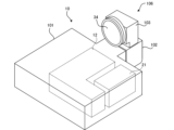
- FIG. 1 is a schematic diagram showing the external configuration of a projection device 10.
- 4 is a schematic cross-sectional view of an optical unit 106 of the projection device 10 shown in FIG. 3.
- FIG. 2 illustrates an example of an information processing apparatus 50 according to an embodiment.
- FIG. 2 is a diagram illustrating an example of a hardware configuration of an information processing device 50.
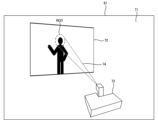
- 7 is a diagram showing a virtual projection surface 72, a virtual projection device 73, and an ROI 1 set in space in the first form.
- FIG. 8 is a diagram showing a first projection area 74 set in the space shown in FIG. 7 .
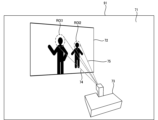
- 13 is a diagram in which ROI1 and ROI2 are designated as partial areas within a virtual projection plane 72.
- FIG. This is a diagram showing a first projection region 74 for ROI1 and a second projection region 75 for ROI2.
- FIG. 13 is a diagram illustrating an example of a projection region based on energy density.
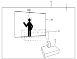
- 7 is a diagram showing a virtual projection surface 72, a virtual projection device 73, an ROI 1, and a test subject region 77 set in space in the second form.
- 13 is a diagram showing a logical product region 78 of a first projection region 74 and a test target region 77.
- FIG. 13 is a diagram showing a logical difference area 79 between a first projection area 74 and a test target area 77.
- FIG. This is a diagram in which a virtual projection plane 72, a virtual projection device 73, an ROI1, and a logical product region 78 are set in space.
- 13 is a diagram showing a logical product region when ROI1 and ROI2 are specified within a virtual projection plane 72.
- FIG. FIG. 13 is a diagram showing an example of a virtual projection image 91 in the third embodiment.
- FIG. 13 is a diagram showing an example of a situation in which a specific object to be detected in a space enters a specific region of the space in the fourth embodiment.
- FIG. 13 is a diagram showing an example of a case where a determination is made based on belongings of a person M.
- FIG. 1 is a schematic diagram illustrating an example of a projection device 10 that is a target for installation support by an information processing device according to an embodiment.
- the information processing device of the embodiment can be used, for example, to assist in the installation of a projection device 10.
- the projection device 10 includes a projection unit 1, a control device 4, and an operation reception unit 2.
- the projection unit 1 is, for example, a liquid crystal projector or a projector using LCOS (Liquid Crystal On Silicon). In the following description, the projection unit 1 is assumed to be a liquid crystal projector.
- the control device 4 is a control device that controls the projection by the projection device 10.
- the control device 4 is a device that includes a control unit composed of various processors, a communication interface (not shown) for communicating with each unit, and a memory 4a such as a hard disk, SSD (Solid State Drive), or ROM (Read Only Memory), and controls the projection unit 1.
- a control unit composed of various processors, a communication interface (not shown) for communicating with each unit, and a memory 4a such as a hard disk, SSD (Solid State Drive), or ROM (Read Only Memory), and controls the projection unit 1.
- the various processors in the control unit of the control device 4 include a CPU (Central Processing Unit), which is a general-purpose processor that executes programs to perform various processes, a programmable logic device (PLD), which is a processor whose circuit configuration can be changed after manufacture, such as an FPGA (Field Programmable Gate Array), or a dedicated electrical circuit, such as an ASIC (Application Specific Integrated Circuit), which is a processor with a circuit configuration designed specifically to perform specific processes.
- a CPU Central Processing Unit
- PLD programmable logic device
- FPGA Field Programmable Gate Array
- ASIC Application Specific Integrated Circuit
- the structure of these various processors is an electric circuit that combines circuit elements such as semiconductor elements.
- the control unit of the control device 4 may be composed of one of the various processors, or may be composed of a combination of two or more processors of the same or different types (for example, a combination of multiple FPGAs or a combination of a CPU and an FPGA).
- the operation reception unit 2 detects instructions from the user by receiving various operations from the user.
- the operation reception unit 2 may be a button, key, joystick, etc. provided on the control device 4, or may be a receiving unit that receives a signal from a remote controller that remotely controls the control device 4.
- the object to be projected 6 is an object such as a screen or a wall that has a projection surface on which a projected image is displayed by the projection unit 1.
- the projection surface of the object to be projected 6 is a rectangular plane.
- the top, bottom, left and right of the object to be projected 6 in FIG. 1 are assumed to be the top, bottom, left and right of the actual object to be projected 6.
- the projection range 11 shown by a dashed line, is the area of the object 6 onto which projection light is irradiated by the projection unit 1.
- the projection range 11 is rectangular.
- the projection range 11 is a part or the entirety of the range within which projection is possible using the projection unit 1.
- the projection unit 1, the control device 4, and the operation reception unit 2 may be realized, for example, by a single device (see, for example, Figs. 3 and 4).
- the projection unit 1, the control device 4, and the operation reception unit 2 may be separate devices that communicate with each other to cooperate.
- FIG. 2 is a schematic diagram showing an example of the internal configuration of the projection unit 1 shown in FIG.
- the projection unit 1 includes a light source 21, a light modulation unit 22, a projection optical system 23, and a control circuit 24.
- the light source 21 includes a light-emitting element such as a laser or an LED (Light Emitting Diode), and emits, for example, white light.
- a light-emitting element such as a laser or an LED (Light Emitting Diode)
- LED Light Emitting Diode
- the light modulation unit 22 is composed of three liquid crystal panels that modulate the three colors of light emitted from the light source 21 and separated into red, blue, and green by a color separation mechanism (not shown) based on image information to emit each color image.
- Each of the three liquid crystal panels may be equipped with a red, blue, and green filter, and the white light emitted from the light source 21 may be modulated by each liquid crystal panel to emit each color image.
- the projection optical system 23 receives light from the light source 21 and the light modulation unit 22 and includes at least one lens, and is composed of, for example, a relay optical system. The light that passes through the projection optical system 23 is projected onto the object 6 to be projected.
- the area of the object 6 onto which light that passes through the entire range of the light modulation unit 22 is irradiated becomes the projectable range where projection by the projection unit 1 is possible. Within this projectable range, the area onto which light that actually passes through the light modulation unit 22 is irradiated becomes the projection range 11. For example, by controlling the size, position, and shape of the area of the light modulation unit 22 through which light passes, the size, position, and shape of the projection range 11 changes within the projectable range.
- the control circuit 24 controls the light source 21, the light modulation unit 22, and the projection optical system 23 based on the display data input from the control device 4, thereby projecting an image based on this display data onto the projection target 6.
- the display data input to the control circuit 24 is composed of three pieces of data: red display data, blue display data, and green display data.
- the control circuit 24 also changes the projection optical system 23 based on a command input from the control device 4, thereby enlarging or reducing the projection range 11 (see FIG. 1) of the projection unit 1.
- the control device 4 may also move the projection range 11 of the projection unit 1 by changing the projection optical system 23 based on an operation from the user received by the operation receiving unit 2.
- the projection device 10 also includes a shift mechanism that mechanically or optically moves the projection range 11 while maintaining the image circle of the projection optical system 23.
- the image circle of the projection optical system 23 is the area through which the projection light incident on the projection optical system 23 passes through the projection optical system 23 appropriately in terms of light intensity loss, color separation, peripheral curvature, etc.
- the shift mechanism is realized by at least one of an optical system shift mechanism that performs an optical system shift and an electronic shift mechanism that performs an electronic shift.
- the optical system shift mechanism is, for example, a mechanism for moving the projection optical system 23 in a direction perpendicular to the optical axis (see, for example, Figures 3 and 4), or a mechanism for moving the light modulation unit 22 in a direction perpendicular to the optical axis instead of moving the projection optical system 23.
- the optical system shift mechanism may also be a mechanism that combines the movement of the projection optical system 23 and the movement of the light modulation unit 22.
- the electronic shift mechanism is a mechanism that shifts the pseudo projection range 11 by changing the range through which light is transmitted in the light modulation section 22.
- the projection device 10 may also include a projection direction change mechanism that moves the projection range 11 together with the image circle of the projection optical system 23.
- the projection direction change mechanism is a mechanism that changes the projection direction of the projection unit 1 by changing the orientation of the projection unit 1 through mechanical rotation (see, for example, Figures 3 and 4).
- Fig. 3 is a schematic diagram showing the external configuration of the projection device 10.
- Fig. 4 is a schematic cross-sectional view of the optical unit 106 of the projection device 10 shown in Fig. 3.
- Fig. 4 shows a cross section taken along a plane along the optical path of light emitted from the main body 101 shown in Fig. 3.
- the projection device 10 includes a main body 101 and an optical unit 106 that protrudes from the main body 101.
- the operation reception unit 2, the control device 4, and the light source 21, light modulation unit 22, and control circuit 24 in the projection unit 1 are provided in the main body 101.
- the projection optical system 23 in the projection unit 1 is provided in the optical unit 106.
- the optical unit 106 includes a first member 102 supported by the main body 101 and a second member 103 supported by the first member 102.
- the first member 102 and the second member 103 may be an integrated member.
- the optical unit 106 may be configured to be detachable from the main body 101 (in other words, replaceable).
- the main body 101 has a housing 15 (see FIG. 4) in which an opening 15a (see FIG. 4) for passing light is formed at the portion connected to the optical unit 106.
- a light source 21 As shown in FIG. 3, inside the housing 15 of the main body 101, there is provided a light source 21, and a light modulation unit 12 including a light modulation section 22 (see FIG. 2) that spatially modulates the light emitted from the light source 21 based on input image data to generate an image.
- a light modulation unit 12 including a light modulation section 22 (see FIG. 2) that spatially modulates the light emitted from the light source 21 based on input image data to generate an image.
- the light emitted from the light source 21 is incident on the light modulation section 22 of the light modulation unit 12, and is spatially modulated by the light modulation section 22 before being emitted.
- the image formed by the light spatially modulated by the light modulation unit 12 passes through the opening 15a of the housing 15 and enters the optical unit 106, where it is projected onto the projection target 6, which is the projection object, and the image G1 becomes visible to the observer.
- the optical unit 106 includes a first member 102 having a hollow portion 2A that is connected to the inside of the main body 101, a second member 103 having a hollow portion 3A that is connected to the hollow portion 2A, a first optical system 121 and a reflecting member 122 that are arranged in the hollow portion 2A, a second optical system 31, a reflecting member 32, a third optical system 33, and a lens 34 that are arranged in the hollow portion 3A, a shift mechanism 105, and a projection direction change mechanism 104.
- the first member 102 is a member having a cross-sectional outer shape that is, for example, rectangular, with the openings 2a and 2b formed on planes perpendicular to each other.
- the first member 102 is supported by the main body 101 with the opening 2a positioned opposite the opening 15a of the main body 101.
- Light emitted from the optical modulation section 22 of the optical modulation unit 12 of the main body 101 passes through the openings 15a and 2a and enters the hollow section 2A of the first member 102.
- direction X1 The direction of light entering hollow portion 2A from main body portion 101 is referred to as direction X1, the opposite direction to direction X1 is referred to as direction X2, and directions X1 and X2 are collectively referred to as direction X.
- direction Z the direction from the front of the paper toward the back and the opposite direction are referred to as direction Z.
- direction Z the direction from the front of the paper toward the back is referred to as direction Z1
- direction Z2 the direction from the back of the paper toward the front is referred to as direction Z2.
- direction Y The direction perpendicular to directions X and Z is referred to as direction Y, and within direction Y, the upward direction in FIG. 4 is referred to as direction Y1, and the downward direction in FIG. 4 is referred to as direction Y2.
- the projection device 10 is disposed so that direction Y2 is the vertical direction.
- the projection optical system 23 shown in FIG. 2 is composed of a first optical system 121, a reflecting member 122, a second optical system 31, a reflecting member 32, a third optical system 33, and a lens 34.
- FIG. 4 shows the optical axis K of the projection optical system 23.
- the first optical system 121, the reflecting member 122, the second optical system 31, the reflecting member 32, the third optical system 33, and the lens 34 are arranged along the optical axis K in this order from the light modulation unit 22 side.
- the first optical system 121 includes at least one lens and guides light traveling in a direction X1 that is incident on the first member 102 from the main body 101 to the reflecting member 122.
- the reflecting member 122 reflects the light incident from the first optical system 121 in the direction Y1.
- the reflecting member 122 is formed of, for example, a mirror.
- the first member 102 has an opening 2b formed on the optical path of the light reflected by the reflecting member 122, and this reflected light passes through the opening 2b and proceeds to the hollow portion 3A of the second member 103.
- the second member 103 is a member with a cross-sectional outer shape that is approximately T-shaped, and an opening 3a is formed in a position facing the opening 2b of the first member 102. Light from the main body 101 that passes through the opening 2b of the first member 102 passes through this opening 3a and enters the hollow portion 3A of the second member 103. Note that the cross-sectional outer shapes of the first member 102 and the second member 103 are arbitrary and are not limited to those described above.
- the second optical system 31 includes at least one lens and guides the light incident from the first member 102 to the reflecting member 32.
- the reflecting member 32 reflects the light incident from the second optical system 31 in the direction X2 and guides it to the third optical system 33.
- the reflecting member 32 is formed of, for example, a mirror.
- the third optical system 33 includes at least one lens and guides the light reflected by the reflecting member 32 to the lens 34.
- the lens 34 is disposed at the end of the second member 103 in the direction X2 so as to cover the opening 3c formed at this end.
- the lens 34 projects the light incident from the third optical system 33 onto the projection target 6.
- the projection direction change mechanism 104 is a rotation mechanism that rotatably connects the second member 103 to the first member 102. This projection direction change mechanism 104 configures the second member 103 to be rotatable around a rotation axis (specifically, the optical axis K) that extends in the direction Y. Note that the projection direction change mechanism 104 is not limited to the arrangement position shown in FIG. 4 as long as it can rotate the optical system. Furthermore, the number of rotation mechanisms is not limited to one, and multiple mechanisms may be provided.
- the shift mechanism 105 is a mechanism for moving the optical axis K of the projection optical system (in other words, the optical unit 106) in a direction perpendicular to the optical axis K (direction Y in FIG. 4). Specifically, the shift mechanism 105 is configured to be able to change the position of the first member 102 in direction Y relative to the main body 101.
- the shift mechanism 105 may be one that moves the first member 102 manually, or one that moves the first member 102 electrically.
- Figure 4 shows a state in which the first member 102 has been moved to its maximum extent in the direction Y1 by the shift mechanism 105.
- the first member 102 is moved in the direction Y2 by the shift mechanism 105 from the state shown in Figure 4, the relative position between the center of the image formed by the light modulation unit 22 (in other words, the center of the display surface) and the optical axis K changes, and the image G1 projected onto the object to be projected 6 can be shifted (translated) in the direction Y2.
- the shift mechanism 105 may be a mechanism that moves the light modulation section 22 in the direction Y instead of moving the optical unit 106 in the direction Y. Even in this case, the image G1 projected onto the projection object 6 can be moved in the direction Y2.
- FIG. 5 is a diagram showing an example of an information processing device 50 according to an embodiment.
- the information processing device 50 according to an embodiment is a tablet terminal or the like having a touch panel 51.
- the touch panel 51 is a display that can be touched.
- the information processing device 50 is used to find a suitable installation position for the projection device 10 and the projection target 6 onto which the light from the projection device 10 is projected.
- a user of the information processing device 50 brings the information processing device 50 into a space (room) where projection by the projection device 10 is to be performed.
- the information processing device 50 displays an installation support image on the touch panel 51 to support the installation of the projection device 10 and the projection target 6 in the space.
- the information processing device 50 displays a second image as an installation assistance image, which is a superimposed image of a virtual projection surface, which is a virtual projection surface, and an image of a virtual projection device, which is a virtual projection device, on a first image obtained by capturing an image of a space in which the projection device 10 is installed and projection is to be performed.
- the user of the information processing device 50 can obtain information regarding the installation of the projection device 10 and the object to be projected 6 while referring to the installation assistance image.
- Fig. 6 is a diagram showing an example of a hardware configuration of the information processing device 50.
- the information processing device 50 shown in Fig. 5 includes, for example, a processor 61, a memory 62, a communication interface 63, a user interface 64, and a sensor 65, as shown in Fig. 6.
- the processor 61, the memory 62, the communication interface 63, the user interface 64, and the sensor 65 are connected by, for example, a bus 69.
- the processor 61 is a circuit that performs signal processing, and is, for example, a CPU that controls the entire information processing device 50.
- the processor 61 may be realized by other digital circuits such as an FPGA or a DSP (Digital Signal Processor).
- the processor 61 may also be realized by combining multiple digital circuits.
- Memory 62 includes, for example, a main memory and an auxiliary memory.
- the main memory is, for example, a RAM (Random Access Memory).
- the main memory is used as a work area for processor 61.
- the auxiliary memory is, for example, a non-volatile memory such as a magnetic disk or a flash memory.
- Various programs that operate the information processing device 50 are stored in the auxiliary memory.
- the programs stored in the auxiliary memory are loaded into the main memory and executed by the processor 61.
- the auxiliary memory may also include a portable memory that is removable from the information processing device 50.
- Portable memories include memory cards such as a Universal Serial Bus (USB) flash drive or a Secure Digital (SD) memory card, and an external hard disk drive.
- USB Universal Serial Bus
- SD Secure Digital
- the communication interface 63 is a communication interface that communicates with devices external to the information processing device 50.
- the communication interface 63 includes at least one of a wired communication interface that communicates via a wire and a wireless communication interface that communicates wirelessly.
- the communication interface 63 is controlled by the processor 61.
- the user interface 64 includes, for example, an input device that accepts operational input from the user and an output device that outputs information to the user.
- the input device can be realized, for example, by keys (e.g., a keyboard) or a remote control.
- the output device can be realized, for example, by a display or a speaker.
- the input device and output device are realized by the touch panel 51.
- the user interface 64 is controlled by the processor 61.
- the information processing device 50 accepts various specifications from the user using the user interface 64.
- the sensor 65 includes an imaging device having an imaging optical system and an imaging element capable of capturing images, and a spatial recognition sensor capable of three-dimensionally recognizing the space around the information processing device 50.
- the imaging device includes, for example, an imaging device provided on the back surface of the information processing device 50 shown in FIG. 5.
- spatial recognition sensor is a LIDAR (Light Detection and Ranging) that emits laser light, measures the time it takes for the laser light to hit an object and bounce back, and measures the distance and direction to the object.
- LIDAR Light Detection and Ranging
- spatial recognition sensors are not limited to this, and can be various types of sensors, such as radar that emits radio waves and ultrasonic sensors that emit ultrasonic waves.
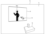
- FIG. 7 is a diagram showing a virtual projection surface 72, a virtual projection device 73, and an ROI 1 set in a space in the first mode.
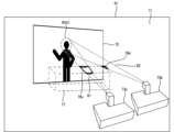
- Fig. 8 is a diagram showing a first projection area 74 set in the space shown in Fig. 7.
- the processor 61 of the information processing device 50 acquires spatial image data representing a spatial image 71 of the physical space in which the projection device 10 is installed and projection is performed by the projection device 10.
- the "spatial image 71" may be, for example, an image of the space captured by an imaging device, or an image generated from a 3D (dimensional) model of the space.
- the imaging device that captures the space may be an imaging device that is provided integrally with the information processing device 50, or may be an external imaging device.
- the spatial image data is, for example, imaging data of the space captured by an imaging device, or image data generated from a 3D model.
- the spatial image 71 is described as a through image (live view image) that shows an image captured by an imaging device in real time.
- the spatial image 71 is an example of a "first image” in the present invention.
- the spatial image data is an example of "first image data" in the present invention.
- the processor 61 determines the position of a virtual projection surface 72, which is a virtual projection surface, and the position of a virtual projection device 73, which is a virtual projection device, in the above space.
- the processor 61 also determines an ROI1 that indicates a portion of the area within the virtual projection surface 72.
- the ROI1 is an area designated as a range in which important information, among the information content projected onto the virtual projection surface 72, is projected.
- the ROI1 is designated as a circular area surrounded by a dashed line.
- the ROI1 is not limited to a portion of the virtual projection surface, and may be, for example, the entire area of the virtual projection surface.
- the shape of the designated ROI1 is not limited to a circle, and may be, for example, a polygonal shape.
- the ROI1 is an example of a "first area" in the present invention.
- the position of the virtual projection surface, the position of the virtual projection device, and ROI1 may be determined based on instructions from a user of the information processing device 50, or may be determined based on an analysis process of the first image.
- the position of ROI1 may be determined to be an approximately fixed position depending on the information content projected onto the virtual projection surface 72, for example, or it may move within the virtual projection surface 72. Specifically, if the information content is a story, the position of the protagonist's face may be the position of ROI1, or if subtitles are displayed, the position of the subtitles, etc.
- the processor 61 determines the first projection area 74 based on the position of the virtual projection surface 72, the position of the virtual projection device 73, and the ROI1, as shown in FIG. 8.
- the first projection area 74 is an area that indicates the range of the projection light projected from the virtual projection device 73 to the ROI1.
- the first projection area 74 is displayed as a continuous projection area from the virtual projection device 73 to the ROI1.
- the first projection area 74 is a cone-shaped projection area that extends from the virtual projection device 73 to the ROI1. However, if the shape of the ROI1 is polygonal, the shape of the first projection area 74 becomes a polygonal pyramid-shaped projection area.
- the processor 61 generates a virtual projection image 91 based on the virtual projection surface 72, the virtual projection device 73, and the first projection area 74.
- the virtual projection image 91 is an image in which the virtual projection surface 72, the virtual projection device 73, and the first projection area 74 are displayed on the spatial image 71.
- the virtual projection image 91 may be generated, for example, as an image in which the first projection area 74 is displayed on the spatial image 71.
- the virtual projection image 91 is an example of a "second image" in the present invention.
- the processor 61 acquires virtual projection image data representing the virtual projection image 91.
- the processor 61 outputs the acquired virtual projection image data to a predetermined output destination.
- the output destination of the virtual projection image data may be, for example, a display unit (touch panel 51) that is integrated into the information processing device 50, or an external display device that is provided externally.
- the virtual projection image data is an example of the "second image data" in the present invention.
- the first information processing device 50 outputs to the touch panel 51 a virtual projection image 91 in which the virtual projection device 73, the virtual projection surface 72, the ROI 1 in the virtual projection surface 72, and the first projection area 74 indicating the range of the projection light from the virtual projection device 73 to the ROI 1 are displayed in the spatial image 71.
- a user who wants to project information content using the projection device 10 can specify the ROI 1 as the area in which important information content is displayed, and the first projection area 74 indicating the range of the projection light projecting the ROI 1 can be displayed.
- This makes it possible to easily recognize the area in space where a shadow is cast in the ROI 1 by, for example, a viewer entering between the virtual projection device 73 and the virtual projection surface 72.
- This makes it easier to design the installation position of the projection device 10, the positions of the surrounding installations, the viewer's movement line, etc. when installing the projection device 10 and the projection target 6, and to modify the information content to be projected, thereby improving convenience.
- Fig. 9 is a diagram showing ROI1 and ROI2 designated as partial regions in a virtual projection plane 72.
- Fig. 10 is a diagram showing a first projection region 74 for ROI1 and a second projection region 75 for ROI2.
- a case where one ROI1 is designated has been described as an example of designating a partial region in the virtual projection plane 72, but the number of designated regions may be multiple as shown in this first modified example.
- ROI2 is a partial area within the virtual projection plane that is different from ROI1.
- ROI2 is specified as a circular area surrounded by a dashed line at the position of the face of the protagonist other than the protagonist for whom ROI1 is specified, out of two protagonists included in the information content.
- ROI2 is an example of a "second area" in the present invention.
- the processor 61 determines the second projection area 75 based on the position of the virtual projection surface 72, the position of the virtual projection device 73, and the ROI2.
- the second projection area 75 is an area that indicates the range of the projection light projected from the virtual projection device 73 to the ROI2.
- the processor 61 generates a virtual projection image 91 based on the virtual projection surface 72, the virtual projection device 73, the second projection area 75, and the first projection area 74.
- the virtual projection image 91 is an image in which the virtual projection surface 72, the virtual projection device 73, the second projection area 75, and the first projection area 74 are displayed on the spatial image 71.
- the virtual projection image 91 may also be generated, for example, as an image in which at least the second projection area 75 and the first projection area 74 are displayed on the spatial image 71.
- the processor 61 acquires virtual projection image data representing the virtual projection image 91, and outputs the acquired virtual projection image data to an output destination (e.g., the touch panel 51, etc.) in the same manner as in the first embodiment described above.
- an output destination e.g., the touch panel 51, etc.
- Fig. 11 is a diagram showing an example of a projection region based on energy density.
- the first projection area 74 is displayed continuously from the virtual projection device 73 to the ROI 1, but the shape of the first projection area 74 may be determined based on predetermined conditions.
- the shape of the first projection area 74 may be determined based on the energy density of the projection light calculated from the specifications of the projection device 10.
- the specifications of the projection device 10 include, for example, the amount of projected light, the angle of view of the lens, etc.
- the viewer may perceive the irradiated projection light as unpleasant glare or unpleasant heat. Whether or not the viewer perceives the projection light as unpleasant glare or unpleasant heat depends on the energy density of the projection light. Therefore, for example, the minimum amount of light energy that is unpleasant to the human eye is detected, and the energy density value per unit area obtained from this is calculated as a threshold value. Specifically, the energy density of the projection light is calculated from the cross-sectional area of the cone-shaped first projection region 74 (see FIG.
- the processor 61 determines the first projection area 76 based on the energy density of the light projected from the virtual projection device 73 onto the ROI 1, as shown in FIG. 11.
- the first projection area 76 is displayed as a cone-shaped first projection area 76 that is cut off midway through the cone-shaped projection area extending from the virtual projection device 73 to the ROI 1.
- the presenter or viewer may turn their face toward the lens of the projection device 10, causing unpleasant glare.
- the shape (length) of the first projection area 76 is set based on a threshold value of the energy density of the light projected from the virtual projection device 73 to the ROI 1.
- the first projection area 74 (see FIG. 8) may be displayed in a different color depending on the energy density of the projection light, for example.
- the projection region with high energy density may be displayed in a dark color, and the projection region with low energy density may be displayed in a light color.
- the projection region on the virtual projection device 73 side with high energy density may be displayed in a dark color, and the projection regions closer to the ROI1 may be displayed in gradually lighter colors.
- the degree of discomfort felt by the viewer is measured based on the energy density of the projection light, and the first projection area 74 is displayed in a different color according to the degree of discomfort. This makes it possible to distinguish between areas where the viewer feels very unpleasant glare and therefore the traffic flow needs to be designed to keep the viewer from entering, and areas where the viewer feels a certain degree of discomfort and therefore the traffic flow needs to be designed to keep the viewer from entering as little as possible. This makes it easier to design traffic flows that can reduce the viewer's discomfort caused by the projection light.
- Fig. 12 is a diagram showing a virtual projection plane 72, a virtual projection device 73, an ROI 1, and a test target area 77 set in space in the second form.
- Fig. 13 is a diagram showing a logical product area 78 between a first projection area 74 and the test target area 77.
- Fig. 14 is a diagram showing a logical difference area 79 between the first projection area 74 and the test target area 77.
- the processor 61 determines the position of the virtual projection surface 72, the position of the virtual projection device 73, the ROI1, and the test target area 77 in the space where the projection by the projection device 10 is performed.
- the test target area 77 is an area assumed to be the movement line of the viewer who views the projected image.
- the test target area 77 is set to an area where the viewer can move between the virtual projection surface 72 and the virtual projection device 73.
- the direction from the virtual projection surface 72 toward the virtual projection device 73 is the depth x direction
- the horizontal direction of the virtual projection surface 72 is the width y direction
- the vertical direction of the virtual projection surface 72 is the height z direction.
- the user of the information processing device 50 specifies the test target area, for example, with the depth x direction being 3 m from the virtual projection surface 72, the width y direction being the same length as the projection range for the virtual projection surface 72, and the height z direction being 1.8 m from the floor.
- the test target area 77 in this example is specified as a rectangular parallelepiped area surrounded by a dashed line in FIG. 12.
- the user may specify, for example, a test target area by inputting a numerical value based on a virtual object, or by having the user hold the device while viewing the projected image and designating the area around the position through which the device passes as the test target area, or by selecting from test target area candidates stored in advance in the information processing device 50.
- the test target area 77 is an example of the "first spatial area" in the present invention.
- the processor 61 determines a first projection area 74 of the projected light projected from the virtual projection device 73 to the ROI1 based on the position of the virtual projection surface 72, the position of the virtual projection device 73, and the ROI1.
- the processor 61 calculates the overlapping area of the first projection area 74 and the test subject area 77 by a logical product operation.
- the processor 61 determines the calculated overlapping area as a logical product area 78 of the first projection area 74 and the test subject area 77.
- the logical product area 78 is displayed as an area surrounded by a thick solid line above the test subject area 77.
- the logical product area 78 is an area that overlaps with the first projection area 74 when the viewer passes through the test subject area 77 and appears as a shadow within the ROI1.
- the processor 61 generates a virtual projection image 91 based on the virtual projection surface 72, the virtual projection device 73, the ROI1, the first projection area 74, the test target area 77, and the logical product area 78.
- the virtual projection image 91 is an image in which the virtual projection surface 72, the virtual projection device 73, the ROI1, the first projection area 74, the test target area 77, and the logical product area 78 are displayed in the spatial image 71.
- the virtual projection image 91 may also be generated, for example, as an image in which the overlapping relationship between the first projection area 74 and the test target area 77 is displayed in the spatial image 71.
- the overlapping relationship being displayed means that at least the logical product area 78 between the first projection area 74 and the test target area 77 is displayed.
- the processor 61 may calculate the area in the test subject area 77 that does not overlap with the first projection area 74 by performing a logical difference operation based on the test subject area 77 and the first projection area 74 shown in FIG. 13.
- the processor 61 may determine the calculated non-overlapping area as a logical difference area 79 as shown in FIG. 14.
- the logical difference area 79 is displayed as an area obtained by removing the logical product area 78 from the test subject area 77.
- the logical difference area 79 is an area in the test subject area 77 that does not overlap with the first projection area 74 even when a viewer passes through it, and does not cast a shadow in ROI1.
- the processor 61 generates a virtual projection image 91 based on the virtual projection surface 72, the virtual projection device 73, the ROI1, and the logical difference area 79.
- the virtual projection image 91 is an image in which the virtual projection surface 72, the virtual projection device 73, the ROI1, and the logical difference area 79 are displayed in the spatial image 71.
- the virtual projection image 91 may also be generated, for example, as an image in which at least the logical difference area 79 between the first projection area 74 and the test subject area 77 is displayed in the spatial image 71.
- the processor 61 acquires virtual projection image data representing the virtual projection image 91, and outputs the acquired virtual projection image data to an output destination (e.g., the touch panel 51, etc.) in the same manner as in the first embodiment described above.
- an output destination e.g., the touch panel 51, etc.
- the area to be secured as the viewer's movement is set as the test target area 77.
- the test target area 77 by determining the overlapping area between the first projection area 74 and the test target area 77 and displaying the overlapping area as a logical product area 78, it is possible to easily grasp whether the viewer's movement and the first projection area 74 overlap, and the size of the overlapping area.
- the area in the test target area 77 that does not overlap with the first projection area 74 and displaying the non-overlapping area as a logical difference area 79 it is possible to easily grasp the viewer's movement area that does not cast a shadow on ROI1.
- FIG. 15 is a diagram in which a virtual projection surface 72, a virtual projection device 73, an ROI1, and a logical product region 78 are set in a space.
- a first projection region 74, a test subject region 77, and a logical product region 78 thereof are displayed in addition to the virtual projection surface 72, the virtual projection device 73, and the ROI1 as images in the space, but the type and number of images to be displayed may be switched by selection.
- the processor 61 may display only the logical product region 78 in addition to the virtual projection surface 72, virtual projection device 73, and ROI 1 as an image in space.
- the type and number of images to be displayed can be switched by touching the touch panel 51 of, for example, the information processing device 50 on which these images are displayed.
- the touch panel 51 it is possible to switch between the virtual projection image 91 of FIG. 13 in which the first projection region 74, the test subject region 77, and their logical product region 78 are displayed in the spatial image 71, and the virtual projection image 91 of FIG. 15 in which the logical product region 78 is displayed in the spatial image 71.
- the type and number of images to be displayed can be changed by selection, so that only the areas necessary for the user can be displayed, making it easier for the user to grasp the position and shape of the areas.
- FIG. 16 is a diagram showing a logical product region when ROI1 and ROI2 are specified within the virtual projection plane 72.
- the processor 61 determines a first projection area 74 of the projected light projected from the virtual projection device 73 onto ROI1, and also determines a second projection area 75 of the projected light projected from the virtual projection device 73 onto ROI2. Then, by performing a logical product operation, the processor 61 determines a logical product area 78a as the overlapping area of the first projection area 74 and the test subject area 77, and also determines a logical product area 78b as the overlapping area of the second projection area 75 and the test subject area 77.
- the logical product area 78b is an area that overlaps with the second projection area 75 when the viewer passes through the test subject area 77, and appears as a shadow within ROI2.
- the processor 61 generates a virtual projection image 91 based on the virtual projection surface 72, the virtual projection device 73, the ROI1, the first projection area 74, the second projection area 75, the test subject area 77, and the logical product areas 78a, 78b.
- the virtual projection image 91 is an image in which the virtual projection surface 72, the virtual projection device 73, the ROI1, the ROI2, the first projection area 74, the second projection area 75, the test subject area 77, and the logical product areas 78a, 78b are displayed in the spatial image 71.
- the virtual projection image 91 may also be generated, for example, as an image in which at least the logical product area 78a between the first projection area 74 and the test subject area 77 and the logical product area 78b between the second projection area 75 and the test subject area 77 are displayed in the spatial image 71.
- FIG. 12 A third modified example of the second embodiment of the processing of the information processing device 50 will be described.
- a case where one test subject area 77 is set in the space where the projection is performed is described, but for example, a plurality of test subject areas may be set in the space.
- the processor 61 determines the logical product area and logical difference area between the first projection area 74 and the two test target areas in the same manner as in Figures 13 and 14 of the second embodiment above.
- the processor 61 generates a virtual projection image 91 in which the logical product area or logical difference area between the first projection area 74 and the two test target areas is displayed, for example.
- the processor 61 acquires virtual projection image data representing the generated virtual projection image 91, and outputs the acquired virtual projection image data to an output destination (e.g., the touch panel 51, etc.) in the same manner as in the first embodiment above.
- the processor 61 determines the area of the ROI1 that corresponds to the logical product area 78 where the first projection area 74 and the test target area 77 overlap.
- the processor 61 displays the area of the ROI1 that corresponds to the logical product area 78 as an area where the projection light is blocked and cast in shadow, for example, assuming that a viewer is present in the logical product area 78.
- the processor 61 displays the area of the ROI1 that corresponds to the logical product area 78, for example, in black or by flashing red.
- the processor 61 generates a virtual projection image 91 that displays, for example, an area of the ROI 1 that corresponds to the logical product area 78 of the first projection area 74 and the test target area 77.
- the processor 61 acquires virtual projection image data that represents the generated virtual projection image 91, and outputs the acquired virtual projection image data to an output destination (for example, the touch panel 51, etc.) in the same manner as in the first embodiment described above.
- Fig. 17 is a diagram showing an example of a virtual projection image 91 in the third mode.
- one information content is displayed (stacking) on one virtual projection surface 72 using a plurality of (two in this example) first virtual projection devices 73a and second virtual projection devices 73b.
- the processor 61 determines the position of the virtual projection surface 72, the position of the first virtual projection device 73a, and the position of the second virtual projection device 73b in the space where projection is performed by the projection device 10.
- the second virtual projection device 73b is a projection device that is specified at a different position from the first virtual projection device 73a.
- the processor 61 determines an ROI1 that indicates a partial area within the virtual projection surface 72.
- the processor 61 also determines a test target area 77 that is expected to be the movement line of the viewer.
- the processor 61 determines a first projection area 81 indicating the range of the light projected from the first virtual projection device 73a to the ROI1 based on the position of the virtual projection surface 72, the position of the first virtual projection device 73a, and the ROI1, and determines a third projection area 82 indicating the range of the light projected from the second virtual projection device 73b to the ROI1 based on the position of the virtual projection surface 72, the position of the second virtual projection device 73b, and the ROI1.
- the processor 61 also performs a logical product operation to determine a logical product area 78c as the overlapping area of the first projection area 81 and the test target area 77, and determines a logical product area 78d as the overlapping area of the third projection area 82 and the test target area 77.
- the processor 61 generates a virtual projection image 91 based on the virtual projection surface 72, the first virtual projection device 73a, the second virtual projection device 73b, the ROI1, the first projection region 81, the third projection region 82, the test target region 77, and the logical product regions 78c, 78d.
- the virtual projection image 91 is an image in which the virtual projection surface 72, the first virtual projection device 73a, the second virtual projection device 73b, the ROI1, the ROI2, the first projection region 81, the third projection region 82, the test target region 77, and the logical product regions 78c, 78d are displayed in the spatial image 71.
- the virtual projection image 91 may also be generated, for example, as an image in which at least the logical product region 78c of the first projection region 81 and the test target region 77, and the logical product region 78d of the third projection region 82 and the test target region 77 are displayed in the spatial image 71.
- the third form of information processing device 50 can achieve the same effects as the first and second forms described above, even when the information content is projected by multiple projection devices through stacking.
- FIG. 18 is a diagram showing an example of a situation in which a specific object detected in a space where projection is performed by the projection device 10 has entered the specific area in the space in the fourth embodiment.
- the information processing device 50 determines the positional relationship between the specific area and the specific object, and notifies the fact when it is determined that the specific object has entered the specific area.
- the positional relationship is, for example, whether or not the specific object overlaps the specific area.
- the processor 61 sets a first projection area 74 based on a virtual projection surface 72, a virtual projection device 73, and an ROI 1 specified in the above space, and determines whether or not a real person M has entered the first projection area 74.
- the first projection area 74 is an example of a "specific area” in the present invention.
- the person M is an example of a "specific object” in the present invention.
- Whether or not person M has entered the first projection area 74 may be detected, for example, based on an image captured by a camera mounted on the information processing device 50, or based on sensing by a three-dimensional sensor (e.g., a lidar) mounted on the information processing device 50.
- a three-dimensional sensor e.g., a lidar mounted on the information processing device 50.
- person M acting as a viewer, is asked to move in the area in front of the virtual projection surface 72, and the movement is captured by a camera mounted on the information processing device 50, and it is determined from the captured image whether or not person M has entered the first projection area 74.
- the processor 61 notifies the result of the determination as to whether or not the person M has entered the first projection area 74, for example, via an output device (such as the touch panel 51 or a speaker) of the information processing device 50. Specifically, the processor 61 displays the portion of the person M that overlaps with the first projection area 74 in the virtual projection image 91 displayed on the touch panel 51 as a high-brightness partial image. The processor 61 may also output an audio message indicating the overlap from the speaker. The processor 61 may also transmit the result of the determination to an information terminal carried by the person M. The result of the determination to be notified may be whether or not the person M who had entered the first projection area 74 has left the first projection area 74.
- an output device such as the touch panel 51 or a speaker
- the fourth form of information processing device 50 when the first projection area 74 is displayed for the purpose of grasping the area where a shadow is cast on the ROI 1, it is possible to easily grasp whether or not the person M, who is playing the role of a viewer, has entered the first projection area 74 by having the person M move along an expected line of movement.
- the first projection area 74 is given as an example of a "specific area” in space, but this is not limiting, and the specific area may be, for example, the logical product area 78 shown in FIG. 13.
- the real person M is given as an example of a "specific object” detected in space, but this is not limiting, and the specific object may be, for example, the information processing device 50 or another information processing device.
- FIG. 19 is a diagram showing an example of a case in which the determination is made based on the belongings of the person M.
- the processor 61 sets a first projection area 74 based on a virtual projection surface 72, a virtual projection device 73, and an ROI 1 specified in the above space, and determines whether a real person M has entered the first projection area 74 based on the position of a smartphone 83 carried by the person M.
- the smartphone 83 is an example of an "information terminal" in the present invention.
- An example of the information terminal carried by the person M may be the information processing device 50 or another information processing device.
- the processor 61 identifies the position of the smartphone 83 carried by the person M by receiving position information transmitted from the smartphone 83 via wireless communication or the like.
- the processor 61 determines a virtual person area 84 by extending the identified position of the smartphone 83 in the height direction.
- the processor 61 determines the positional relationship between the virtual person area 84 and the first projection area 74.
- the virtual person area 84 is set as an area in which the smartphone 83 exists in the horizontal direction and an area of a predetermined length from the floor in the height direction.
- the area in which the smartphone 83 exists may be, for example, an area at the point where the smartphone 83 is carried by the person M.
- the predetermined length from the floor is the expected height of the person M (for example, 180 cm).
- the processor 61 determines whether the virtual person area 84 enters the first projection area 74 from the determined positional relationship between the first projection area 74 and the virtual person area 84.
- the processor 61 notifies the result of the determination as to whether the virtual person area 84 has entered the first projection area 74, for example, using a light-emitting unit of the smartphone 83 carried by the person M.
- the light-emitting unit of the smartphone 83 includes, for example, the display and backlight of the smartphone 83.
- the processor 61 displays a high-brightness image on the display of the smartphone 83. This creates an effect as if light from the virtual projection device 73 is reflecting off the smartphone 83.
- the processor 61 may also notify the result of the determination as to whether the virtual person area 84 has entered the first projection area 74 via the touch panel 51, speaker, etc. of the information processing device 50, as in the fourth embodiment.
- ⁇ Sixth mode of processing of information processing device 50> A sixth embodiment of the processing of the information processing device 50 will be described.
- a new device is installed in the space where the projection device 10 performs projection, and the effective area of the device is determined.
- the device is, for example, a sensor such as an infrared sensor.
- the effective area is the range in which the sensor can collect information.
- the processor 61 determines the overlap area between the effective area of the device and a specific area in the space where the projection is performed. For example, the processor 61 determines the overlap area between the effective area of the device and the first projection area 74 and the test target area 77 described above by a logical AND operation. The processor 61 generates a virtual projection image 91 in which the effective area of the device, the first projection area 74, the test target area 77, and the overlap area between these areas are displayed in the spatial image 71, for example. The processor 61 acquires virtual projection image data representing the virtual projection image 91, and outputs the acquired virtual projection image data to an output destination (e.g., the touch panel 51, etc.) in the same manner as in the first embodiment described above.
- an output destination e.g., the touch panel 51, etc.
- One example of such operations is to install an infrared sensor with a detection range near the front of the projection screen of the projection device 10, detect a child who is interested in the image displayed on the projection screen of the projection device 10 and approaches with the infrared sensor, and project an image of flowers blooming on the projection screen based on the detection of the child by the infrared sensor.
- Another example of operations is to detect the position of a person giving a presentation in front of the projection screen of the projection device 10 with an infrared sensor, and based on the detection of the presenter's position by the infrared sensor, control the position of the image of the operation button projected so that the presenter can operate it on the projection screen of the projection device 10 to be moved to a position on the projection screen of the projection device 10 that is easy for the presenter to operate as the presentation progresses.
- the device having an effective area may be a device that acts on the effective area, such as a device that emits wind, water, or a smell when a child approaches.
- the sixth embodiment by displaying the overlapping area between the effective area of the device, the first projection area 74, and the test target area 77, it is possible to easily grasp whether the movement of a viewer approaching the effective area of the device affects the projection onto ROI1. This allows the positions of the virtual projection device 73, the virtual projection surface 72, and the device in space to be set appropriately.
- the control method described in the above embodiment can be realized by executing a prepared control program on a computer.
- This control program is recorded on a computer-readable storage medium and executed by reading it from the storage medium.
- This control program may be provided in a form stored in a non-transitory storage medium such as a flash memory, or provided via a network such as the Internet.
- the computer that executes this control program may be included in the control device, or may be included in an electronic device such as a smartphone, tablet terminal, or personal computer that can communicate with the control device, or may be included in a server device that can communicate with these control devices and electronic devices.
Landscapes
- Engineering & Computer Science (AREA)
- Multimedia (AREA)
- Signal Processing (AREA)
- Physics & Mathematics (AREA)
- Computer Hardware Design (AREA)
- General Physics & Mathematics (AREA)
- Theoretical Computer Science (AREA)
- Transforming Electric Information Into Light Information (AREA)
- Controls And Circuits For Display Device (AREA)
Priority Applications (2)
| Application Number | Priority Date | Filing Date | Title |
|---|---|---|---|
| JP2025505169A JPWO2024185422A1 (https=) | 2023-03-03 | 2024-02-14 | |
| US19/316,904 US20260006153A1 (en) | 2023-03-03 | 2025-09-02 | Information processing apparatus, information processing method, and information processing program |
Applications Claiming Priority (2)
| Application Number | Priority Date | Filing Date | Title |
|---|---|---|---|
| JP2023-032762 | 2023-03-03 | ||
| JP2023032762 | 2023-03-03 |
Related Child Applications (1)
| Application Number | Title | Priority Date | Filing Date |
|---|---|---|---|
| US19/316,904 Continuation US20260006153A1 (en) | 2023-03-03 | 2025-09-02 | Information processing apparatus, information processing method, and information processing program |
Publications (1)
| Publication Number | Publication Date |
|---|---|
| WO2024185422A1 true WO2024185422A1 (ja) | 2024-09-12 |
Family
ID=92674581
Family Applications (1)
| Application Number | Title | Priority Date | Filing Date |
|---|---|---|---|
| PCT/JP2024/005004 Ceased WO2024185422A1 (ja) | 2023-03-03 | 2024-02-14 | 情報処理装置、情報処理方法、及び情報処理プログラム |
Country Status (3)
| Country | Link |
|---|---|
| US (1) | US20260006153A1 (https=) |
| JP (1) | JPWO2024185422A1 (https=) |
| WO (1) | WO2024185422A1 (https=) |
Citations (4)
| Publication number | Priority date | Publication date | Assignee | Title |
|---|---|---|---|---|
| WO2017179272A1 (ja) * | 2016-04-15 | 2017-10-19 | ソニー株式会社 | 情報処理装置、情報処理方法、及びプログラム |
| WO2022138240A1 (ja) * | 2020-12-25 | 2022-06-30 | 富士フイルム株式会社 | 設置支援装置、設置支援方法、及び設置支援プログラム |
| JP2022114688A (ja) * | 2021-01-27 | 2022-08-08 | セイコーエプソン株式会社 | 表示方法および表示システム |
| JP2022114697A (ja) * | 2021-01-27 | 2022-08-08 | セイコーエプソン株式会社 | 表示方法および表示システム |
-
2024
- 2024-02-14 WO PCT/JP2024/005004 patent/WO2024185422A1/ja not_active Ceased
- 2024-02-14 JP JP2025505169A patent/JPWO2024185422A1/ja active Pending
-
2025
- 2025-09-02 US US19/316,904 patent/US20260006153A1/en active Pending
Patent Citations (4)
| Publication number | Priority date | Publication date | Assignee | Title |
|---|---|---|---|---|
| WO2017179272A1 (ja) * | 2016-04-15 | 2017-10-19 | ソニー株式会社 | 情報処理装置、情報処理方法、及びプログラム |
| WO2022138240A1 (ja) * | 2020-12-25 | 2022-06-30 | 富士フイルム株式会社 | 設置支援装置、設置支援方法、及び設置支援プログラム |
| JP2022114688A (ja) * | 2021-01-27 | 2022-08-08 | セイコーエプソン株式会社 | 表示方法および表示システム |
| JP2022114697A (ja) * | 2021-01-27 | 2022-08-08 | セイコーエプソン株式会社 | 表示方法および表示システム |
Also Published As
| Publication number | Publication date |
|---|---|
| JPWO2024185422A1 (https=) | 2024-09-12 |
| US20260006153A1 (en) | 2026-01-01 |
Similar Documents
| Publication | Publication Date | Title |
|---|---|---|
| JP6186599B1 (ja) | 投影装置 | |
| WO2007013215A1 (ja) | 画像表示装置 | |
| JPH1124839A (ja) | 情報入力装置 | |
| CN107113949A (zh) | 照明装置 | |
| CN115113216A (zh) | 检测装置、检测方法以及空间投影装置 | |
| US20240019715A1 (en) | Air floating video display apparatus | |
| EP4245252A1 (en) | Oral image processing device and oral image processing method | |
| CN112019674B (zh) | 电子装置的控制方法及电子装置 | |
| CN115112042A (zh) | 检测装置、检测方法以及空间投影装置 | |
| JP6935713B2 (ja) | 位置検出装置、位置検出システム及び位置検出装置の制御方法 | |
| CN116783644A (zh) | 空间悬浮影像显示装置 | |
| WO2018078777A1 (ja) | 空中映像表示システム、波長選択結像装置、映像表示装置、及び空中映像表示方法 | |
| JP2015064459A (ja) | 映像投射装置及び映像投射システム | |
| JP7372485B2 (ja) | 設置支援装置、設置支援方法、及び設置支援プログラム | |
| WO2024185422A1 (ja) | 情報処理装置、情報処理方法、及び情報処理プログラム | |
| JP4712754B2 (ja) | 情報処理装置及び情報処理方法 | |
| KR101002071B1 (ko) | 멀티 적외선 카메라 방식의 투영 영상 터치 장치 | |
| JP2014182332A (ja) | サイネージ装置 | |
| JP4687820B2 (ja) | 情報入力装置及び情報入力方法 | |
| JP6740614B2 (ja) | 物体検出装置、及び物体検出装置を備えた画像表示装置 | |
| US20200019050A1 (en) | Display system | |
| JP2014233005A (ja) | 画像表示装置 | |
| JP7709444B2 (ja) | 制御装置、制御方法、制御プログラム、及び投影システム | |
| US20250016293A1 (en) | Information processing apparatus, information processing method, and information processing program | |
| JP7266151B2 (ja) | 指示位置検出装置、指示位置検出方法、指示位置検出プログラム、及び投影システム |
Legal Events
| Date | Code | Title | Description |
|---|---|---|---|
| 121 | Ep: the epo has been informed by wipo that ep was designated in this application |
Ref document number: 24766794 Country of ref document: EP Kind code of ref document: A1 |
|
| ENP | Entry into the national phase |
Ref document number: 2025505169 Country of ref document: JP Kind code of ref document: A |
|
| WWE | Wipo information: entry into national phase |
Ref document number: 2025505169 Country of ref document: JP |
|
| NENP | Non-entry into the national phase |
Ref country code: DE |
|
| 122 | Ep: pct application non-entry in european phase |
Ref document number: 24766794 Country of ref document: EP Kind code of ref document: A1 |