WO2024185076A1 - ロボット装置、制御システム、制御方法、及びプログラム - Google Patents
ロボット装置、制御システム、制御方法、及びプログラム Download PDFInfo
- Publication number
- WO2024185076A1 WO2024185076A1 PCT/JP2023/008820 JP2023008820W WO2024185076A1 WO 2024185076 A1 WO2024185076 A1 WO 2024185076A1 JP 2023008820 W JP2023008820 W JP 2023008820W WO 2024185076 A1 WO2024185076 A1 WO 2024185076A1
- Authority
- WO
- WIPO (PCT)
- Prior art keywords
- person
- unit
- robot device
- camera
- face
- Prior art date
- Legal status (The legal status is an assumption and is not a legal conclusion. Google has not performed a legal analysis and makes no representation as to the accuracy of the status listed.)
- Ceased
Links
Images


Classifications
-
- B—PERFORMING OPERATIONS; TRANSPORTING
- B25—HAND TOOLS; PORTABLE POWER-DRIVEN TOOLS; MANIPULATORS
- B25J—MANIPULATORS; CHAMBERS PROVIDED WITH MANIPULATION DEVICES
- B25J5/00—Manipulators mounted on wheels or on carriages
-
- G—PHYSICS
- G06—COMPUTING OR CALCULATING; COUNTING
- G06T—IMAGE DATA PROCESSING OR GENERATION, IN GENERAL
- G06T7/00—Image analysis
-
- H—ELECTRICITY
- H04—ELECTRIC COMMUNICATION TECHNIQUE
- H04N—PICTORIAL COMMUNICATION, e.g. TELEVISION
- H04N7/00—Television systems
- H04N7/18—Closed-circuit television [CCTV] systems, i.e. systems in which the video signal is not broadcast
Definitions
- This disclosure relates to a robot device, a control system, a control method, and a program.
- Facial recognition is sometimes used in surveillance operations. Facial recognition is performed by comparing the facial features of people registered in advance with the facial features of people in images captured by a camera. However, the accuracy of facial recognition can be reduced if the person in the image has their back turned and their face is not visible, or if the person is visible but facing the camera, depending on the direction of their face.
- the purpose of this disclosure is to provide a robotic device that can perform face recognition with high accuracy.
- the robot device includes a camera that captures an image including a person, a drive unit that moves the robot device, a detection unit that detects a person or the face of the person from an image captured by the camera, a determination unit that determines whether facial authentication can be performed on the person detected by the detection unit, and a control unit that controls the drive unit so that the robot device moves to a position where facial authentication is possible or moves along a path when the determination unit determines that facial authentication cannot be performed.
- This disclosure provides a robot device that can perform face recognition with high accuracy.
- FIG. 1 is a diagram showing an overview of a first embodiment.
- FIG. 2 is a diagram illustrating hardware included in the robot device of the first embodiment. 2 is a block diagram showing the functions of the robot device according to the first embodiment.
- FIG. 4A and 4B are diagrams illustrating an example of a detection frame according to the first embodiment.
- 5A to 5C are diagrams illustrating a specific example of a method for calculating a destination position in the first embodiment.
- FIG. 2 is a diagram for explaining a target position in the first embodiment.
- 5 is a flowchart showing an example of a process executed by the robot device of the first embodiment.
- 10 is a flowchart illustrating an example of a destination position calculation process according to the first embodiment.
- FIG. 11 is a diagram showing a control system according to a second embodiment.
- FIG. 11 is a diagram illustrating hardware included in an information processing device according to a second embodiment.
- FIG. 11 is a block diagram showing the functions of an information processing device according to
- Fig. 1 is a diagram showing an overview of the first embodiment.
- Fig. 1 shows a robot device 100.
- the robot device 100 is a device that executes a control method.
- the robot device 100 is an autonomous robot.
- the robot device 100 performs a monitoring task.
- the robot device 100 has a camera.
- FIG. 1 shows a person 10.
- the person 10 is facing backwards. Therefore, the robot device 100 cannot capture an image of the face of the person 10. Therefore, the robot device 100 goes around.
- the lower diagram in FIG. 1 shows the state when the robot device 100 and the person 10 are viewed from above. As shown in the lower diagram in FIG. 1, the robot device 100 goes around. This allows the robot device 100 to capture an image of the face of the person 10. Therefore, the robot device 100 can obtain an image including the face.
- the robot device 100 will now be described in detail.
- the robot device 100 includes a processor 101, a volatile storage device 102, a non-volatile storage device 103, a camera 104, and a driving unit 105.
- the processor 101 controls the entire robot device 100.
- the processor 101 is a CPU (Central Processing Unit) or an FPGA (Field Programmable Gate Array).
- the processor 101 may be a multiprocessor.
- the robot device 100 may also have a processing circuit.
- the volatile memory device 102 is the main memory device of the robot device 100.
- the volatile memory device 102 is a RAM (Random Access Memory).
- the non-volatile memory device 103 is the auxiliary memory device of the robot device 100.
- the non-volatile memory device 103 is a HDD (Hard Disk Drive) or an SSD (Solid State Drive).
- the camera 104 is an RGB (Red Green Blue) camera, an RGB-D (Depth) camera, or an infrared camera.
- the camera 104 captures an image of an object.
- the camera 104 captures an image of the person 10.
- the driving unit 105 drives the robot device 100 .
- the robot device 100 includes a storage unit 110, an imaging unit 120, an acquisition unit 130, a detection unit 140, a determination unit 150, a calculation unit 160, and a control unit 170.
- the storage unit 110 may be realized as a storage area secured in the volatile storage device 102 or the non-volatile storage device 103 .
- the imaging unit 120 is realized by the camera 104 .
- Some or all of the acquiring unit 130, the detecting unit 140, the determining unit 150, the calculating unit 160, and the control unit 170 may be realized by a processing circuit.
- some or all of the acquiring unit 130, the detecting unit 140, the determining unit 150, the calculating unit 160, and the control unit 170 may be realized as modules of a program executed by the processor 101.
- the program executed by the processor 101 is also called a control program.
- the control program is recorded on a recording medium.
- the storage unit 110 stores various information.
- the imaging unit 120 captures an image using the camera 104 .
- the acquisition unit 130 acquires the image captured by the imaging unit 120.
- the acquisition unit 130 acquires position information of the robotic device 100.
- the acquisition unit 130 acquires the position information of the robotic device 100 from a GPS (Global Positioning System) sensor included in the robotic device 100.
- GPS Global Positioning System
- the detection unit 140 detects a person or a person's face from the image captured by the camera 104.
- the detection is performed using image recognition technology.
- the image recognition technology may be a technology that uses a trained model, or a technology that uses Haar-Like features.
- the determination unit 150 determines whether or not the face of a person appearing in an image can be authenticated. First, the determination unit 150 determines whether or not the person was detected by the detection unit 140. If a person was detected, the determination unit 150 determines whether or not the detected detection frame is larger than a certain size. If it is determined that the detection frame is larger, the detection unit 140 performs face detection, and the determination unit 150 determines whether or not the face was detected. If a face was detected, the determination unit 150 determines whether or not face authentication can be performed. The determination of whether or not face authentication can be performed is performed as follows. First, the facial features of a person whose face has been detected are extracted.
- the facial features of a plurality of people registered in a database are compared with the facial features of the person photographed by the camera. Whether or not face authentication is possible is determined based on whether the degree of match between the features in the comparison is equal to or exceeds a predetermined value.
- the database that stores information about the facial features of people for face authentication is a storage device or recording medium that can read and write information, and is, for example, placed on a cloud or in a building where the robot device performs monitoring and transmits and receives information to and from the robot device via a network, or is attached to the robot device.
- the robot device 100 moves by moving closer to capture a larger image of the face of the person or by changing its direction to capture the face of the person as close as possible to the front, so that the face of the person can be authenticated with high accuracy.
- Taking a larger picture of a person's face refers to processing including enlarging the detection frame of a person or face captured in the camera.
- Taking a picture of a face from as far in front as possible refers to an action including movement to capture a picture of a person captured in the camera from the front or diagonally in front.
- the movement of the robot device 100 can be, for example, by moving closer to the person so that the detection frame for detecting the person or the person's face becomes larger, or by moving to a calculated position where the accuracy of extracting or matching facial features when authenticating the person's face will be high (also called a position where the person's face is clearly visible). These methods will be described in detail later.
- a method for the robot device 100 to move based on the size of the detection frame will be described.
- the control unit 170 may control the driving unit 105 to move closer to the person.
- an example of the detection frame is shown.
- FIG. 4A and 4B are diagrams showing examples of detection frames in the first embodiment.
- FIG. 4A shows an image 20.
- the image 20 includes a person.
- FIG. 4A shows a detection frame 21.
- the determination unit 150 determines whether or not the face of the person can be recognized. If the detection frame 21 in which the detection unit 140 detects a person is small, the distance between the robot device 100 and the person is far, so the determination unit 150 may not be able to detect the face even if the person is facing forward. Therefore, the control unit 170 controls the driving unit 105 to approach the person. The distance to approach the person may be determined in advance. The control unit 170 also controls the driving unit 105 to align the center position in the width direction of the image captured by the camera with the center position 22 of the detection frame 21.
- This control allows the robot to move toward the direction 23 in which the person is located.
- the control unit 170 instructs the camera 104 to capture an image.
- the camera 104 captures an image of the person.
- FIG. 4(B) shows an image 30 obtained by capturing the image.
- FIG. 4(B) shows a detection frame 31. Note that the detection frame 31 is larger than a predetermined frame. This means that the distance between the robot device 100 and the person is short, and it is expected that the accuracy of face detection and face authentication after the person is detected will improve.
- a method for the robot device 100 to calculate and move to a position where a person's face is best captured by the camera will be described.
- the calculation unit 160 calculates a position where face recognition is possible.
- the calculation of the position will be described using a specific example.
- the position will be referred to as a target position.
- FIG. 5 is a diagram showing a specific example of a method for calculating a target position in the first embodiment.
- FIG. 5 shows a distance 40 between the robot device 100 and the person 10.
- the distance 40 is also called a first distance.
- the distance 40 is obtained by the following method.
- the acquisition unit 130 acquires the trained model from the storage unit 110 or an external device.
- the external device is a cloud server. Note that a diagram of the external device is omitted.
- the acquisition unit 130 inputs an image into the trained model, and the trained model outputs a distance of 40. In this way, the acquisition unit 130 can obtain the distance of 40.
- the acquisition unit 130 acquires the distance 40 from an image captured by the RGB camera using the Shape From Focus/Defocus method.
- the acquisition unit 130 acquires the distance 40 based on the approximate height of the person 10, the height of the detection frame in the image, the focal length, and the similarity relationship of the distance 40.
- the acquisition unit 130 acquires depth information obtained from the generated image as a distance of 40.
- the acquisition unit 130 acquires the distance 40 based on information obtained from the infrared sensor.
- the acquisition unit 130 acquires the distance 40 based on information obtained from the distance sensor.
- the distance sensor here is, for example, a LiDAR.
- the acquisition unit 130 acquires the distance 41 between the person 10 and the destination position 42.
- the distance 41 is a predetermined distance.
- the acquisition unit 130 acquires the distance 41 from the storage unit 110 or an external device.
- the distance 41 is also referred to as the second distance.
- the calculation unit 160 may subtract a value from the distance 41 if the statistically processed value of the brightness of the image is equal to or less than a predetermined value. For example, an average value based on a predetermined sample may be used as the statistical processing.
- the calculation unit 160 may also perform statistical processing on the brightness of the entire image, or on the brightness within a detection frame in which a person or face is detected. If the statistically processed value is equal to or less than the value, it means that the image is dark overall. In other words, it means that the brightness of the environment when the person 10 is imaged is dark. Therefore, if the robot device 100 captures an image at the target position 42 without changing the distance 41, the brightness of the image obtained by the image capture is dark.
- the calculation unit 160 shortens the distance 41. As a result, if the robot device 100 captures an image at the target position 42, the size of the face included in the image obtained by the image capture becomes larger. This improves the accuracy of face recognition.
- the acquisition unit 130 may directly acquire information relating to distance from the external device or various sensor devices described above, or may indirectly acquire information relating to distance by converting information output from the external device or the device itself. In other words, the acquisition unit 130 not only performs information acquisition processing, but also performs arithmetic processing such as converting the acquired information into information relating to distance.
- the calculation unit 160 may add a value to the distance 41 if the height of the detection frame in the image is equal to or greater than a predetermined value. This allows the robot device 100 to capture an image of an appropriate size even if a tall person is detected.
- the acquisition unit 130 also acquires information indicating the direction of the person 10 or the direction of the face of the person 10, which is determined from the image captured by the camera 104.
- the direction of the person 10 or the information indicating the direction of the face of the person 10 here is determined using image analysis technology.
- the direction of the person 10 captured by the camera 104 or the information indicating the direction of the face of the person 10 is also referred to as direction information.
- the information indicating the direction of the person 10 is not limited to being determined from external features such as the skeletal shape of the person 10, but may also be determined using information regarding the direction in which the person 10 moves when walking or running.
- the calculation unit 160 calculates the destination position 42 based on the position information of the robot device 100, the above-mentioned orientation information, distance 40, and distance 41.
- the control unit 170 controls the drive unit 105 and the imaging unit 120 to point the camera 104 toward the face of the person 10.
- the robot device 100 uses the information on the destination position 42 calculated by the calculation unit 160 to capture an image of the person 10 with the camera 104 when moving around to get in front of the person 10 or after moving around to get in front of the person 10.
- direction information not only information indicating the direction of the person's face 10, but also information indicating the direction of the person 10 can be used as direction information.
- the direction of the person's face 10 is basically directed forward. However, if there is something of concern, the person may turn his/her face in a direction other than the front by, for example, shaking his/her head. Therefore, if the direction of the face changes unexpectedly, first, information on the direction of the person 10 is identified.
- the information on the direction of the person 10 it is possible to estimate the direction of the face when the person 10 turns to the front or turns his/her face at a predetermined angle from the front, that is, when he/she turns his/her head at a predetermined angle, and generate information on the direction of the face of the person 10.
- information indicating the direction of the person 10 can also be used as information indicating the direction of the person's face 10, and therefore the identified information indicating the direction of the person 10 can also be used as direction information for face authentication of the person 10.
- the information on the facial orientation of person 10 may include not only the facial orientation when facing forward, but also, for example, the facial orientation when facing a direction within an angle range of 0° to 45° directly in front of the face, as described below. Furthermore, this angle range may be used as a predetermined angle when generating information on the facial orientation of person 10 from the orientation of person 10.
- the acquisition unit 130 may also acquire information related to orientation, associate the acquired orientation information with information about the person 10 and information about the face of the person 10, and store these in the memory unit 110 of the robot device 100 or in a memory unit of a control system described below.
- the calculation unit 160 may calculate a path along which the robot device 100 moves to the calculated destination position 42, that is, a movement path.
- the method for calculating the movement path at this time may be a method of linearly interpolating the position information of the robot device 100 and the destination position 42, or a method of two-dimensionally interpolating in a wraparound manner using spline interpolation or the like.
- the robot device 100 may also move along the movement path calculated in this manner.
- Fig. 6 is a diagram for explaining a target position in the first embodiment. It is desirable that the target position 42 is a position that is in front of the face. In Fig. 6, the target position 42a is a position that is in front of the face.
- the target position 42 for the robot device 100 to perform face authentication does not necessarily have to be a position in front of the face. For example, the target position 42 may be in the range of angles from 0° directly in front of the face to positions 42b and 42c shifted by 45°.
- image information for authentication in which the face of a known person who is known not to be a suspicious person is captured from the front or at an angle is recorded in advance in a database, and the robot device 100 moves so as to capture the face of the person from a direction that can capture the facial features contained in this recorded image information. Therefore, the more directions in which the face of a known person is captured as image information for authentication, the easier it is for the robot device 100 to use the camera to perform authentication.
- facial information of the same person may be registered in the database under different shooting conditions or shooting directions, and more information indicating facial features may be recorded to enable smooth matching and authentication, or a technology may be used to three-dimensionally estimate the shape or features of the face that are not included when the image is captured for at least one of the facial information registered in the database and the face to be authenticated, thereby enabling highly versatile matching.
- facial recognition can be performed smoothly, it will be possible to quickly determine whether the person is a known person registered in the database or not, which will increase the practicality of surveillance using the camera mounted on the robot device 100.
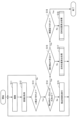
- FIG. 7 is a flowchart illustrating an example of a process executed by the robot device according to the first embodiment.
- the imaging unit 120 captures an image.
- the acquisition unit 130 acquires the image captured by the imaging unit 120 .
- the detection unit 140 performs human detection on the image obtained by the acquisition unit 130. The detection unit 140 judges whether or not a human has been detected. If a human has been detected, the process proceeds to step S14. If a human has not been detected, the control unit 170 controls the robot device 100 to perform monitoring work on a different area. Then, the process proceeds to step S11.
- Step S14 The determination unit 150 determines whether the size of the detection frame in which the detection unit 140 detects a person is equal to or larger than a certain size. If the size of the detection frame is smaller than the certain size, the process proceeds to step S15. If the size of the detection frame is larger than the certain size, the process proceeds to step S16. (Step S15) The control unit 170 controls the robot device 100 to approach the monitoring target. Then, the process proceeds to step S11. (Step S16) The determination unit 150 determines whether or not the face of the person can be detected. If the face of the person can be detected, the process proceeds to step S18. If the face of the person cannot be detected, the process proceeds to step S17.
- Step S17 The robot device 100 executes a destination position calculation process. After that, the control unit 170 controls the robot device 100 to move to the calculated destination position. Note that the robot device 100 may move along the calculated movement path instead of moving to the calculated destination position. Then, the process proceeds to step S11.
- Step S18 The robot device 100 performs face authentication.
- the robot device 100 judges the result of the face authentication. If the face authentication is successful, the process ends. If the face authentication is not successful, the process proceeds to step S19.
- Step S19 The robot device 100 executes a destination position calculation process. After that, the control unit 170 controls the robot device 100 to move to the calculated destination position. Note that the robot device 100 may move along the calculated movement path instead of moving to the calculated destination position. Then, the process proceeds to step S11.
- Step S21 The acquisition unit 130 acquires the distance 40.
- Step S22 The acquisition unit 130 acquires orientation information.
- Step S23 The acquisition unit 130 acquires the distance 41.
- Step S24 The acquisition unit 130 acquires the position information of the robot device 100.
- Step S25 The calculation unit 160 calculates the destination position 42 based on the orientation information, the position information of the robot device 100, the distance 40, and the distance 41.
- the determination unit 150 may determine that face recognition is not possible, and may interrupt the face recognition process and output an alert if the number of times face recognition is not possible exceeds a predetermined number, in order to avoid the face recognition process being continued repeatedly.
- the robot device 100 is present on a certain floor in a building.
- the robot device 100 is patrolling at night.
- the robot device 100 captures an image of the surroundings.
- a person is included in the image obtained by capturing the image.
- the person has his/her back turned. Therefore, the robot device 100 cannot detect the face of the person.
- the robot device 100 moves to a target position.
- the robot device 100 captures an image of the person.
- the robot device 100 performs face authentication. If the person is not a security guard or an employee, the robot device 100 outputs an alert.
- the robot device 100 when the robot device 100 is unable to capture an image of a person's face, it moves to a position where it can capture an image of the person's face. Then, the robot device 100 captures an image of the person's face. In this way, the robot device 100 can obtain an image that includes the face.
- Embodiment 2 Next, a description will be given of embodiment 2. In embodiment 2, differences from embodiment 1 will be mainly described. Furthermore, in embodiment 2, description of matters common to embodiment 1 will be omitted. In the first embodiment, the case has been described where all the processes are executed by the robot device 100. In the second embodiment, a case will be described where some of the processes are executed by an external device.
- the control system includes an information processing device 200 and a robotic device 300.
- the information processing device 200 and the robotic device 300 communicate with each other via a network.
- the information processing device 200 is a server.
- the robot device 300 includes a camera and a driving unit.
- the information processing apparatus 200 includes a processor 201, a volatile storage device 202, and a non-volatile storage device 203.
- the processor 201 controls the entire information processing device 200.
- the processor 201 is a CPU, an FPGA, or the like.
- the processor 201 may be a multiprocessor.
- the information processing device 200 may also have a processing circuit.
- the volatile storage device 202 is the main storage device of the information processing device 200.
- the volatile storage device 202 is a RAM.
- the non-volatile storage device 203 is the auxiliary storage device of the information processing device 200.
- the non-volatile storage device 203 is a HDD or SSD.
- the information processing device 200 includes a storage unit 210, an acquisition unit 220, a detection unit 230, a determination unit 240, a calculation unit 250, and a control unit 260.
- the storage unit 210 may be realized as a storage area secured in the volatile storage device 202 or the non-volatile storage device 203 .
- the acquiring unit 220, the detecting unit 230, the determining unit 240, the calculating unit 250, and the control unit 260 may be partly or entirely implemented by a processing circuit. Also, the acquiring unit 220, the detecting unit 230, the determining unit 240, the calculating unit 250, and the control unit 260 may be partly or entirely implemented as a program module executed by the processor 201.
- the acquisition unit 220 acquires an image captured by a camera possessed by the robot device 300, position information of the robot device 300, the distance 40 between the robot device 300 and a person, and a predetermined distance 41.
- the functions of the acquisition unit 220, detection unit 230, determination unit 240, and calculation unit 250 are almost the same as the functions of the acquisition unit 130, detection unit 140, determination unit 150, and calculation unit 160. Therefore, detailed descriptions of the functions of the acquisition unit 220, detection unit 230, determination unit 240, and calculation unit 250 will be omitted.
- the control unit 260 instructs the robot device 300 to move to the target position 42 and to take an image at the target position 42 .
- the robot device 300 receives the instruction, it moves to the destination position 42.
- the robot device 300 arrives at the destination position 42, it captures an image of the person.
- control unit 260 may instruct the robot device 300 to move closer to the person.
- the control unit 260 may also calculate the center coordinates of the detection frame, identify the direction of the center coordinates, and instruct the robot device 300 to move in that direction.
- the robot device 300 when the robot device 300 is unable to capture an image of a person's face, it moves to a position where it can capture an image of the person's face. Then, the robot device 300 captures an image of the person's face. This allows the control system to obtain an image that includes the face.
- the information processing device 200 has the storage unit 210, the acquisition unit 220, the detection unit 230, the determination unit 240, the calculation unit 250, and the control unit 260, but is not limited to this. For example, some of these may be included in the robot device 300.
- 10 person 20 image, 21 detection frame, 22 center coordinates, 23 direction, 30 image, 31 detection frame, 40 distance, 41 distance, 42 target position, 42a target position, 42b, 42c position, 100 robot device, 101 processor, 102 volatile storage device, 103 non-volatile storage device, 104 camera, 105 drive unit, 110 memory unit, 120 imaging unit, 130 acquisition unit, 140 detection unit, 150 determination unit, 160 calculation unit, 170 control unit, 200 information processing device, 201 processor, 202 volatile storage device, 203 non-volatile storage device, 210 storage unit, 220 acquisition unit, 230 detection unit, 240 determination unit, 250 calculation unit, 260 control unit, 300 robot device.
Landscapes
- Engineering & Computer Science (AREA)
- Robotics (AREA)
- Mechanical Engineering (AREA)
- Computer Vision & Pattern Recognition (AREA)
- Physics & Mathematics (AREA)
- General Physics & Mathematics (AREA)
- Theoretical Computer Science (AREA)
- Multimedia (AREA)
- Signal Processing (AREA)
- Manipulator (AREA)
Priority Applications (2)
| Application Number | Priority Date | Filing Date | Title |
|---|---|---|---|
| PCT/JP2023/008820 WO2024185076A1 (ja) | 2023-03-08 | 2023-03-08 | ロボット装置、制御システム、制御方法、及びプログラム |
| JP2023545932A JP7690039B2 (ja) | 2023-03-08 | 2023-03-08 | ロボット装置、制御システム、制御方法、及びプログラム |
Applications Claiming Priority (1)
| Application Number | Priority Date | Filing Date | Title |
|---|---|---|---|
| PCT/JP2023/008820 WO2024185076A1 (ja) | 2023-03-08 | 2023-03-08 | ロボット装置、制御システム、制御方法、及びプログラム |
Publications (1)
| Publication Number | Publication Date |
|---|---|
| WO2024185076A1 true WO2024185076A1 (ja) | 2024-09-12 |
Family
ID=92674319
Family Applications (1)
| Application Number | Title | Priority Date | Filing Date |
|---|---|---|---|
| PCT/JP2023/008820 Ceased WO2024185076A1 (ja) | 2023-03-08 | 2023-03-08 | ロボット装置、制御システム、制御方法、及びプログラム |
Country Status (2)
| Country | Link |
|---|---|
| JP (1) | JP7690039B2 (https=) |
| WO (1) | WO2024185076A1 (https=) |
Citations (4)
| Publication number | Priority date | Publication date | Assignee | Title |
|---|---|---|---|---|
| JP2005193351A (ja) * | 2004-01-09 | 2005-07-21 | Honda Motor Co Ltd | 顔画像取得方法およびそのシステム |
| JP2006179023A (ja) * | 2006-02-13 | 2006-07-06 | Nec Corp | ロボット装置 |
| JP2020057149A (ja) * | 2018-10-01 | 2020-04-09 | カシオ計算機株式会社 | 画像処理装置、ロボット、画像処理方法及びプログラム |
| WO2022137720A1 (ja) * | 2020-12-21 | 2022-06-30 | パナソニックIpマネジメント株式会社 | 在席情報管理システムおよび在席情報管理方法 |
-
2023
- 2023-03-08 JP JP2023545932A patent/JP7690039B2/ja active Active
- 2023-03-08 WO PCT/JP2023/008820 patent/WO2024185076A1/ja not_active Ceased
Patent Citations (4)
| Publication number | Priority date | Publication date | Assignee | Title |
|---|---|---|---|---|
| JP2005193351A (ja) * | 2004-01-09 | 2005-07-21 | Honda Motor Co Ltd | 顔画像取得方法およびそのシステム |
| JP2006179023A (ja) * | 2006-02-13 | 2006-07-06 | Nec Corp | ロボット装置 |
| JP2020057149A (ja) * | 2018-10-01 | 2020-04-09 | カシオ計算機株式会社 | 画像処理装置、ロボット、画像処理方法及びプログラム |
| WO2022137720A1 (ja) * | 2020-12-21 | 2022-06-30 | パナソニックIpマネジメント株式会社 | 在席情報管理システムおよび在席情報管理方法 |
Also Published As
| Publication number | Publication date |
|---|---|
| JP7690039B2 (ja) | 2025-06-09 |
| JPWO2024185076A1 (https=) | 2024-09-12 |
Similar Documents
| Publication | Publication Date | Title |
|---|---|---|
| TWI466545B (zh) | 攝影機裝置及利用其進行影像監控的方法 | |
| CN108111818B (zh) | 基于多摄像机协同的运动目标主动感知方法和装置 | |
| JP5688456B2 (ja) | 熱画像座標を用いた保安用カメラ追跡監視システム及び方法 | |
| JP4642128B2 (ja) | 画像処理方法、画像処理装置及びシステム | |
| JP5567853B2 (ja) | 画像認識装置および方法 | |
| JP6532217B2 (ja) | 画像処理装置、画像処理方法、及び画像処理システム | |
| JP3801137B2 (ja) | 侵入物体検出装置 | |
| KR101530255B1 (ko) | 객체 자동 추적 장치가 구비된 cctv 시스템 | |
| US20140022351A1 (en) | Photographing apparatus, photographing control method, and eyeball recognition apparatus | |
| CN102196240B (zh) | 摄像装置及利用其动态侦测监控对象的方法 | |
| JP5001930B2 (ja) | 動作認識装置及び方法 | |
| JP6973175B2 (ja) | 画像選択プログラム、情報処理装置、システム、および画像選択方法 | |
| CN108243304A (zh) | 枪球一体式动态人脸抓拍专用摄像机及动态人脸抓拍方法 | |
| JP4604606B2 (ja) | 顔検出装置及び顔検出方法、並びにコンピュータ・プログラム | |
| JP6624800B2 (ja) | 画像処理装置、画像処理方法、及び画像処理システム | |
| JP5159390B2 (ja) | 物体検知方法及びその装置 | |
| KR101290517B1 (ko) | 촬영장치 및 이의 대상 추적방법 | |
| JP7690039B2 (ja) | ロボット装置、制御システム、制御方法、及びプログラム | |
| JP2024127882A (ja) | ロボット装置、制御システム、制御方法、及びプログラム | |
| Fahn et al. | A high-definition human face tracking system using the fusion of omni-directional and PTZ cameras mounted on a mobile robot | |
| JP2021022783A (ja) | 制御装置、追尾システム、制御方法、及びプログラム | |
| JP2007134845A (ja) | カメラ制御装置およびカメラ制御プログラム | |
| CN110580427A (zh) | 一种人脸检测方法、装置及设备 | |
| JP2019192155A (ja) | 画像処理装置、撮影装置、画像処理方法およびプログラム | |
| JP2018051669A (ja) | ロボットシステム及びプログラム |
Legal Events
| Date | Code | Title | Description |
|---|---|---|---|
| WWE | Wipo information: entry into national phase |
Ref document number: 2023545932 Country of ref document: JP |
|
| 121 | Ep: the epo has been informed by wipo that ep was designated in this application |
Ref document number: 23926288 Country of ref document: EP Kind code of ref document: A1 |
|
| NENP | Non-entry into the national phase |
Ref country code: DE |
|
| 122 | Ep: pct application non-entry in european phase |
Ref document number: 23926288 Country of ref document: EP Kind code of ref document: A1 |