WO2024185035A1 - コイルボビンおよびリアクトル - Google Patents
コイルボビンおよびリアクトル Download PDFInfo
- Publication number
- WO2024185035A1 WO2024185035A1 PCT/JP2023/008598 JP2023008598W WO2024185035A1 WO 2024185035 A1 WO2024185035 A1 WO 2024185035A1 JP 2023008598 W JP2023008598 W JP 2023008598W WO 2024185035 A1 WO2024185035 A1 WO 2024185035A1
- Authority
- WO
- WIPO (PCT)
- Prior art keywords
- flange
- coil bobbin
- cylindrical body
- inclined portion
- wire
- Prior art date
- Legal status (The legal status is an assumption and is not a legal conclusion. Google has not performed a legal analysis and makes no representation as to the accuracy of the status listed.)
- Ceased
Links
Images







Classifications
-
- H—ELECTRICITY
- H01—ELECTRIC ELEMENTS
- H01F—MAGNETS; INDUCTANCES; TRANSFORMERS; SELECTION OF MATERIALS FOR THEIR MAGNETIC PROPERTIES
- H01F37/00—Fixed inductances not covered by group H01F17/00
-
- H—ELECTRICITY
- H01—ELECTRIC ELEMENTS
- H01F—MAGNETS; INDUCTANCES; TRANSFORMERS; SELECTION OF MATERIALS FOR THEIR MAGNETIC PROPERTIES
- H01F5/00—Coils
- H01F5/02—Coils wound on non-magnetic supports, e.g. formers
Definitions
- This disclosure relates to coil bobbins and reactors.
- reactors have been developed that have a core body that includes an outer core and multiple cores arranged inside the outer core. Each of the multiple cores is inserted into a coil. Strictly speaking, the coil is made by winding wire around a coil bobbin.
- multiple protrusions are provided on the wound portion of the coil bobbin (for example, JP 2021-083216 A).
- the protrusions are dimensioned and positioned such that a wire having a particular diameter is positioned in the gap between the protrusions. Therefore, when another wire having a diameter different from the particular diameter is wound around the coil bobbin, the other wire is not positioned in the gap between the protrusions, and thus the wire may become unwound.
- a coil bobbin that includes a cylindrical body having a circumferential surface around which a wire is to be wound, a first flange disposed at one end of the cylindrical body, and a second flange disposed at the other end of the cylindrical body, and at least a portion of the circumferential surface of the cylindrical body adjacent to the first flange is formed with an inclined portion that is inclined toward the central axis of the coil bobbin.
- FIG. 1 is a perspective view of a coil bobbin according to the prior art.
- FIG. 1 is a side view of a coil bobbin according to the prior art.
- FIG. 1 is a top view of a coil bobbin according to the prior art.
- FIG. 3B is a partial cross-sectional view of the coil bobbin shown in FIG. 3A.
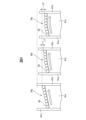
- 10A to 10C are partial cross-sectional views of a coil bobbin showing a number of modified examples.
- FIG. 11 is a partial cross-sectional view of a coil bobbin showing another modified example.
- FIG. 11 is a side view of a coil bobbin according to the second embodiment.
- FIG. 6B is a cross-sectional view taken along line BB of FIG. 6A.
- FIG. 11 is a partial cross-sectional view of a coil bobbin according to a third embodiment.
- FIG. 10 is a partial cross-sectional view of a coil bobbin according to a fourth embodiment.
- FIG. 2 is a first perspective view for explaining a manufacturing method of a reactor.
- FIG. 11 is a second perspective view for explaining the method for manufacturing the reactor.
- FIG. 11 is a cross-sectional view of a core body included in a reactor based on another embodiment.
- a three-phase reactor will be mainly described as an example, but the application of the present disclosure is not limited to three-phase reactors, and can be widely applied to multi-phase reactors in which a certain inductance is required in each phase.
- the reactor according to the present disclosure is not limited to those provided on the primary and secondary sides of inverters in industrial robots and machine tools, and can be applied to various devices.
- FIG. 1A is a cross-sectional view of a reactor including a coil bobbin based on a first embodiment.
- FIG. 1B is a perspective view of the reactor shown in FIG. 1A.
- the core body 5 of the reactor 6 includes an outer peripheral iron core 20 and three iron core coils 31-33 arranged inside the outer peripheral iron core 20.
- the iron core coils 31-33 are arranged inside the approximately hexagonal outer peripheral iron core 20. These iron core coils 31-33 are arranged at equal intervals in the circumferential direction of the core body 5.
- the outer core 20 may have another rotationally symmetric shape, such as a circle. Also, the number of core coils may be any multiple of three, in which case the reactor 6 can be used as a three-phase reactor.
- each of the core coils 31-33 includes an iron core 41-43 that extends only in the radial direction of the outer core 20, and a coil 51-53 attached to the iron core.
- Each of the at least three coils 51-53 is housed in a coil bobbin 61-63.
- the coil bobbins 61-63 are preferably formed from a non-magnetic material, such as resin. Note that in some drawings, the coils 51-53 may be omitted for the sake of simplicity.
- the outer core 20 is composed of multiple, for example three, outer core portions 24-26 divided in the circumferential direction.
- the outer core portions 24-26 are integrally formed with the cores 41-43, respectively.
- the outer core portions 24-26 and the cores 41-43 are formed by laminating multiple magnetic plates, for example iron plates, carbon steel plates, electromagnetic steel plates, or from pressed powder cores.
- the outer core 20 is composed of multiple outer core portions 24-26 in this way, it can be easily manufactured even if the outer core 20 is large. Note that the number of cores 41-43 and the number of outer core portions 24-26 do not necessarily have to match.
- each of the cores 41 to 43 are located near the center of the outer core 20.
- the radially inner ends of each of the cores 41 to 43 converge toward the center of the outer core 20, with a tip angle of approximately 120 degrees.
- the radially inner ends of the cores 41 to 43 are separated from each other by magnetically connectable gaps 101 to 103.
- the radially inner end of the core 41 is separated from the radially inner end of each of the two adjacent cores 42, 43 by gaps 101, 103.
- the same is true for the other cores 42, 43.
- the dimensions of the gaps 101 to 103 are assumed to be equal to each other.
- the configuration shown in FIG. 1A does not require a central core located at the center of the core body 5, so the core body 5 can be constructed lighter and more simply. Furthermore, because the three iron core coils 31-33 are surrounded by the outer periphery iron core 20, the magnetic field generated from the coils 51-53 does not leak outside the outer periphery iron core 20. Also, the gaps 101-103 can be provided at any thickness and at low cost, which is advantageous in terms of design compared to reactors of conventional structures.
- the difference in magnetic path length between phases is smaller than in reactors of conventional structure. Therefore, in the present disclosure, it is also possible to reduce the imbalance in inductance caused by the difference in magnetic path length.
- FIG. 2A is a perspective view of a coil bobbin in the first embodiment
- FIGS. 2B and 2C are a side view and a top view, respectively, of the coil bobbin shown in FIG. 2A.
- only coil bobbin 61 is shown as a representative, but the other coil bobbins 62, 63, (64) are assumed to have the same configuration.
- the coil bobbin 61 is composed of a cylindrical body 61c having a peripheral surface around which the wire 50, for example a wire having a circular cross section, is wound, a first flange 61a disposed at one end of the cylindrical body 61c, and a second flange 61b disposed at the other end of the cylindrical body 61c.
- the peripheral surface of the cylindrical body 61c has an inclined portion 70a that inclines toward the central axis O of the coil bobbin 61.
- the distance between the central axis O near the second flange 61b and the side of the cylindrical body 61c is longer than the distance between the central axis O near the first flange 61a and the side of the cylindrical body 61c.
- FIG. 2C also shows that the distance between the central axis O near the second flange 61b and the side of the cylindrical body 61c is longer than the distance between the central axis O near the first flange 61a and the side of the cylindrical body 61c.
- the cross-sectional area of the peripheral surface of the cylindrical body 61c adjacent to the first flange 61a is smaller than the cross-sectional area of the peripheral surface of the cylindrical body 61c adjacent to the second flange 61b.
- Figure 2E is a cross-sectional view taken along line A-A in Figure 2B. From Figures 2B, 2C, and 2E, it can be seen that the inclined portion 70a is formed over the entire circumferential surface of the cylindrical body 61c, and that the inclined portion 70a extends from the first flange 61a to the second flange 61b. Furthermore, Figure 2E shows the through hole 69 of the coil bobbin 61 into which the iron core 41 should be inserted.
- FIG. 2D is a partial cross-sectional view of the coil bobbin shown in FIG. 2A.
- FIG. 2D shows wire 50 wound around coil bobbin 61.
- wire 50 begins to be wound from the position of cylinder 61c adjacent to first flange 61a.
- wire 50 may have a circular cross section as shown in FIG. 2A, or wire 50 may be a rectangular wire having a rectangular cross section.
- the wire 50 is wound while being pressed against the first flange 61a or an adjacent already wound wire 50. Because the inclined portion described above is formed in the cylindrical body 61c, there is a possibility that the wound wire 50 may slide toward the first flange 61a when the wire 50 is wound one or more times. However, the wire 50 does not slide along the cylindrical body 61c toward the second flange 61b. Therefore, even if the wire 50 continues to be wound in the direction shown by the arrow in FIG. 2D, the wire will not collapse.
- FIG. 2F is a partial cross-sectional view of a coil bobbin in a modified example.
- wire 50' is wound around it.
- the diameter of wire 50' is larger than the diameter of wire 50.
- wire 50' can be wound around a cylindrical body 61c on which a sloping portion 70a is formed in the same manner. This is because there is no need to form a protruding piece as shown in FIG. 3D, which will be described later.
- wire 50' can be wound well. Therefore, the same coil bobbin 61 can be used even when the diameter of the wire is changed.
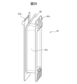
- FIG. 3A is a perspective view of a coil bobbin in the prior art
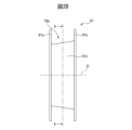
- FIG. 3B is a side view of a coil bobbin in the prior art
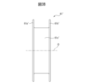
- FIG. 3C is a top view of a coil bobbin in the prior art.
- a coil bobbin 61' is shown that has a cylindrical body 61c' between a first flange 61a' and a second flange 61b'.
- the side of the cylindrical body 61c' is parallel to the central axis O. Therefore, the inclined portion 70a is not formed on the cylindrical body 61c'.
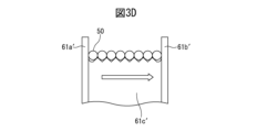
- FIG. 3D is a partial cross-sectional view of the coil bobbin shown in FIG. 3A.
- a number of protrusions are formed on the surface of the cylindrical body 61c'. These protrusions have dimensions and spacing suitable for receiving the wire 50.
- the wire 50 engages with the protrusions in sequence each time it is wound, and therefore does not collapse.
- the prior art had the disadvantage that it was necessary to form the multiple protrusions in advance.
- the protrusions correspond to a specific dimension of the wire 50, there was a problem that collapse would occur when winding a wire of a different dimension (not shown).
- FIG. 4 is a partial cross-sectional view of a coil bobbin showing several modified examples.
- the left side of FIG. 4 shows the same inclined portion 70a as in FIG. 2D.
- the inclination angle of the inclined portion 70a relative to the central axis O (not shown in FIG. 4, etc.) is constant, and the inclined portion 70a is formed from the first flange 61a to the second flange 61b. Therefore, the wire 50 can be wound well from the start to the end of winding the wire 50.
- the inclined portion 70b shown in the center of FIG. 4 is also formed from the first flange 61a to the second flange 61b.
- the inclination angle of the inclined portion 70b on the first flange 61a side with respect to the central axis O (not shown in FIG. 4, etc.) is equal to the inclination angle of the inclined portion 70a.
- the inclination angle of inclined portion 70b with respect to central axis O on the second flange 61b side is smaller than the inclination angle of inclined portion 70a.
- the distance between central axis O on the second flange 61b side and the side of cylindrical body 61c is smaller by a deviation L1 than the distance between central axis O on the second flange 61b side and the side of cylindrical body 61c.
- the coil bobbin 61 can be made smaller.
- the inclination angle of the inclined portion 70b is different in two regions.
- the inclination angle of the inclined portion 70b may be different in three or more regions. In this case, it is desirable to make the inclination angle of the inclined portion 70b adjacent to the first flange 61a larger than the inclination angle of the other regions, thereby achieving the same effect as described above.
- the inclination angle of the inclined portion 70b on the second flange 61b side is 0° or more.
- the wire 50 can be wound more easily in areas with a small inclination angle than in areas with a large inclination angle. Therefore, by providing areas with a relatively small inclination angle, the efficiency of the winding operation of the wire 50 can be improved.
- the inclination angle of the inclined portion 70c with respect to the central axis O on the first flange 61a side shown on the right side of Figure 4 is equal to the inclination angle of the inclined portion 70a.
- the inclination angle of the inclined portion 70c with respect to the central axis O on the second flange 61b side is smaller than the inclination angle of the inclined portion 70a, for example, 0°.
- the distance between the central axis O on the second flange 61b side and the side of the cylindrical body 61c is smaller than the distance between the central axis O on the second flange 61b side and the side of the cylindrical body 61c by a deviation L2.
- the coil bobbin 61 can be made even smaller.
- the inclination angle is 0°
- the efficiency of the winding work of the wire 50 in that portion can be further improved.
- the inclined portion 70c is formed only on the first flange 61a side of the peripheral surface of the cylindrical body 61c.
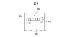
- FIG. 5 is a partial cross-sectional view of a coil bobbin showing another modified example.
- the inclination angle of the inclined portion 70d on the first flange 61a side and the second flange 61b side in FIG. 5 is the same as the inclination angle of the inclined portion 70a described above.
- the inclination angle of the central portion of the inclined portion 70d is smaller than the inclination angle of the inclined portion 70d on the first flange 61a side and the second flange 61b side, and is, for example, 0°.
- the coil bobbin 61 can be made smaller and the efficiency of the winding work of the wire 50 can be improved.
- the inclination angle of the inclined portion 70d on the first flange 61a side and the inclination angle of the inclined portion 70d on the second flange 61b side may be different from each other. However, it is preferable that the inclination angle of the inclined portion 70d on the first flange 61a side is larger than the inclination angle of the inclined portion 70d on the second flange 61b side. This makes it possible to obtain the same effect as described above.
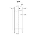
- FIG. 6A is a side view of a coil bobbin in the second embodiment
- FIG. 6B is a cross-sectional view taken along line B-B in FIG. 6A
- the upper line segment showing part of the circumferential surface of the cylindrical body 61c is an inclined line
- the lower line segment showing another part of the circumferential surface of the cylindrical body 61c is perpendicular to the first flange 61a and the second flange 61b.
- the inclined portion 70e is formed only on a part of the circumferential surface, not on the entire circumferential surface of the cylindrical body 61c.
- the through hole 69 is a substantially rectangular shape that corresponds to the shape of the insertion portion of the iron core 41.
- the through hole 69 has four corners 81 to 84.
- the inclined portion 70e is formed in a region of the circumferential surface of the cylindrical body 61c that includes one corner 81. In this way, it is preferable that the inclined portion 70e is formed in a region that includes at least one corner.
- the inclined portion 70e can be formed in the region of at least one of the corners 81-84, so the region in which the inclined portion 70e is formed can be adjusted to the minimum necessary.
- the inclined portion 70e may be formed in a region including two of the four corners 81-84, or in a region including three corners. In such cases, the same effect as described above can be obtained.
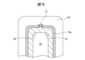
- FIG. 7A is a partial cross-sectional view of a coil bobbin based on the third embodiment.
- FIG. 7A roughly corresponds to a portion of FIG. 2E, and shows an inclined portion 70a similar to that described above.
- a protrusion 72 is formed on the inclined portion 70a at a position corresponding to the position between the two corners 81, 84. It is preferable that the protrusion 72 is formed at least partially from the first flange 61a toward the second flange 61b.
- the upper surface of the protrusion 72 may be inclined at the same angle as the inclined portion 70a, but the upper surface of the protrusion 72 may have a larger angle of inclination than the inclined portion 70a, which further prevents the wire 50 from sliding toward the second flange 61b.
- Multiple protrusions 72 may be formed in the area between the corners 81 and 84, and the protrusions 72 may be formed at positions corresponding to any of the four corners 81 to 84.
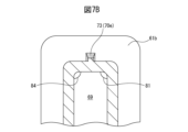
- FIG. 7B is a partial cross-sectional view of a coil bobbin based on the fourth embodiment.
- inclined portion 70a is not formed, and instead, protrusion 73 similar to protrusion 72 is formed at a position corresponding to between corners 81 and 84.
- the upper surface of protrusion 73 is inclined at the same inclination angle as inclined portion 70a or at a different inclination angle. Therefore, protrusion 73 can be said to be inclined portion 70f formed only on a portion of the circumferential surface of cylindrical body 61c, and protrusion 73 plays a similar role to inclined portions 70a to 70e described above.
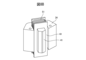
- FIGS. 8A and 8B are perspective views for explaining a method for manufacturing a reactor. As shown in these drawings, a coil bobbin 61 around which a coil 51 is wound is inserted into the corresponding core 41 of the outer core portion 24.
- coils 52, 53 are similarly attached to the core 42 of the other outer core portion 25 and the core 43 of the outer core portion 26 via coil bobbins 62, 63, respectively.
- these outer core portions 24 to 26 are assembled together in the circumferential direction, thereby creating the reactor 6.
- the first flange 61a may be pushed by the coil bobbin 61 and come off the cylindrical body 61c. For this reason, it is preferable to position the coil bobbin 61 so that the first flange 61a is positioned radially outward of the reactor 6. In this case, even if the coil bobbin 61 and the first flange 61a slide, they will stop at the outer circumferential core 20.
- the coil bobbin 61 is positioned so that the first flange 61a is located radially inside the reactor 6, the coil bobbin 61 and other components may fall off through the gaps 101 to 103.
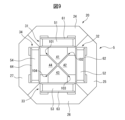
- FIG. 9 is a top view of a core body of a reactor in another embodiment.
- the core body 5 shown in FIG. 9 includes an approximately octagonal outer core 20 and four iron core coils 31-34 similar to those described above, which are arranged inside the outer core 20. These iron core coils 31-34 are arranged at equal intervals around the circumference of the core body 5. It is also preferable that the number of iron cores is an even number equal to or greater than four, so that a reactor equipped with the core body 5 can be used as a single-phase reactor.
- the outer core 20 is composed of four outer core portions 24-27 divided in the circumferential direction.
- Each core coil 31-34 includes a radially extending core 41-44 and a coil 51-54 attached to the core.
- the radially outer end of each of the cores 41-44 is formed integrally with each of the outer core portions 21-24. Note that the number of cores 41-44 does not necessarily have to match the number of outer core portions 24-27.
- each of the cores 41-44 are located near the center of the outer core 20.
- the radially inner ends of each of the cores 41-44 converge toward the center of the outer core 20, with a tip angle of approximately 90 degrees.
- the radially inner ends of the cores 41-44 are separated from each other via magnetically connectable gaps 101-104.
- FIG. 9 at least three coils 51-54 are also housed in coil bobbins 61-64 similar to those described above.
- the coil bobbins 61-64 are provided with the inclined portions 70a and the like described above. Therefore, even in the case shown in FIG. 9, the same effects as those described above can be obtained.
- the coil bobbins 61-64 themselves that are provided with the inclined portions 70a and the like are also considered to be within the scope of this disclosure.
- the advantage of at least one of the embodiments described above is that, because the inclined portion is formed at least partially on the circumferential surface of the cylindrical body, it is possible to prevent the winding from collapsing, and it is possible to provide a coil bobbin on which wires of different diameters can be wound.
- a cylinder having a circumferential surface around which the wire is to be wound; A first flange disposed at one end of the cylindrical body; a second flange disposed at the other end of the barrel; A cross-sectional area of the peripheral surface of the cylindrical body adjacent to the first flange is smaller than a cross-sectional area of the peripheral surface of the cylindrical body adjacent to the second flange.
- (Appendix 6) an outer core composed of a plurality of outer core portions; At least three cores coupled to the plurality of outer periphery core portions; a coil wound around the coil bobbin according to claim 1 and inserted into the at least three iron cores; A reactor, wherein a magnetically connectable gap is formed between one of the at least three iron cores and another iron core adjacent to the one iron core.
- (Appendix 7) 7. The reactor of claim 6, wherein the number of the at least three iron cores and coils is a multiple of three.
- (Appendix 8) 7. The reactor according to claim 6, wherein the number of the at least three iron cores and coils is an even number greater than or equal to four.
- Reference Signs List 5 Core body 6 Reactor 20 Outer periphery core 24-27 Outer periphery core portion 31-34 Core coil 41-44 Core 50 Wire rod 51-54 Coil 61-64 Coil bobbin 61a First flange 61b Second flange 61c Cylinder 69 Opening 70a-70f Inclined portion 72, 73 Protrusion 81-84 Corner portion 101-104 Gap
Landscapes
- Engineering & Computer Science (AREA)
- Power Engineering (AREA)
- Insulating Of Coils (AREA)
Abstract
コイルボビンは、線材が巻付けられるべき周面を有する筒体と、筒体の一端に配置された第一フランジと、筒体の他端に配置された第二フランジと、を含む。前記第一フランジに隣接する前記筒体の前記周面の少なくとも一部分には、前記コイルボビンの中心軸線に向かって傾斜する傾斜部が形成されている。
Description
本開示は、コイルボビンおよびリアクトルに関する。
近年では、外周部鉄心と該外周部鉄心の内部に配置された複数の鉄心とを含むコア本体を備えたリアクトルが開発されている。複数の鉄心のそれぞれは、コイルに挿入されている。厳密に言えば、コイルは、線材をコイルボビンに巻回することにより作成されている。
コイルボビン上における線材の巻崩れを防止するために、コイルボビンの被巻回部に複数の突片部を設けることが行われている(例えば特開2021-083216号公報)。
しかしながら、複数の突片部は、特定の直径を有する線材が複数の突片部の間の隙間に配置されるように寸法決めおよび位置決めされている。従って、特定の直径とは異なる直径を有する他の線材を前述したコイルボビンに巻回すると、他の線材は突片部の間の隙間に配置されず、従って、線材の巻崩れが発生する場合がある。
それゆえ、特定の直径とは異なる直径を有する線材であっても、線材の巻崩れを防止することのできるコイルボビンおよびそのようなコイルボビンを備えたリアクトルが望まれている。
本開示の1番目の態様によれば、コイルボビンにおいて、線材が巻付けられるべき周面を有する筒体と、該筒体の一端に配置された第一フランジと、前記筒体の他端に配置された第二フランジと、を具備し、前記第一フランジに隣接する前記筒体の前記周面の少なくとも一部分には、前記コイルボビンの中心軸線に向かって傾斜する傾斜部が形成されている、コイルボビンが提供される。
本開示の目的、特徴及び利点は、添付図面に関連した以下の実施形態の説明により一層明らかになろう。
以下、添付図面を参照して本開示の実施の形態を説明する。全図面に渡り、対応する構成要素には共通の参照符号を付す。
以下の記載では、三相リアクトルを例として主に説明するが、本開示の適用は、三相リアクトルに限定されず、各相で一定のインダクタンスが求められる多相リアクトルに対して幅広く適用可能である。また、本開示に係るリアクトルは、産業用ロボットや工作機械におけるインバータの一次側および二次側に設けるものに限定されず、様々な機器に対して適用することができる。
以下の記載では、三相リアクトルを例として主に説明するが、本開示の適用は、三相リアクトルに限定されず、各相で一定のインダクタンスが求められる多相リアクトルに対して幅広く適用可能である。また、本開示に係るリアクトルは、産業用ロボットや工作機械におけるインバータの一次側および二次側に設けるものに限定されず、様々な機器に対して適用することができる。
図1Aは第一の実施形態に基づくコイルボビンを含むリアクトルの断面図である。図1Bは図1Aに示されるリアクトルの斜視図である。図1Aおよび図1Bに示されるように、リアクトル6のコア本体5は、外周部鉄心20と、外周部鉄心20の内側に配置された三つの鉄心コイル31~33とを含んでいる。図1においては、略六角形の外周部鉄心20の内側に鉄心コイル31~33が配置されている。これら鉄心コイル31~33はコア本体5の周方向に等間隔で配置されている。
なお、外周部鉄心20が他の回転対称形状、例えば円形であってもよい。また、鉄心コイルの数は3の倍数であればよく、その場合には、リアクトル6を三相リアクトルとして使用できる。
図面から分かるように、それぞれの鉄心コイル31~33は、外周部鉄心20の半径方向にのみ延びる鉄心41~43と、該鉄心に装着されたコイル51~53とを含んでいる。少なくとも三つのコイル51~53のそれぞれがコイルボビン61~63に収納されている。コイルボビン61~63は非磁性材料、例えば樹脂から形成されるのが好ましい。なお、一部の図面においては、簡潔にする目的で、コイル51~53の図示を省略する場合がある。
外周部鉄心20は周方向に分割された複数、例えば三つの外周部鉄心部分24~26より構成されている。外周部鉄心部分24~26は、それぞれ鉄心41~43に一体的に構成されている。外周部鉄心部分24~26および鉄心41~43は、複数の磁性板、例えば鉄板、炭素鋼板、電磁鋼板を積層するか、または圧粉鉄心から形成される。このように外周部鉄心20が複数の外周部鉄心部分24~26から構成される場合には、外周部鉄心20が大型である場合であっても、そのような外周部鉄心20を容易に製造できる。なお、鉄心41~43の数と、外周部鉄心部分24~26の数とが必ずしも一致していなくてもよい。
さらに、鉄心41~43のそれぞれの半径方向内側端部は外周部鉄心20の中心近傍に位置している。図面においては鉄心41~43のそれぞれの半径方向内側端部は外周部鉄心20の中心に向かって収斂しており、その先端角度は約120度である。そして、鉄心41~43の半径方向内側端部は、磁気的に連結可能なギャップ101~103を介して互いに離間している。
言い換えれば、鉄心41の半径方向内側端部は、隣接する二つの鉄心42、43のそれぞれの半径方向内側端部とギャップ101、103を介して互いに離間している。他の鉄心42、43についても同様である。なお、ギャップ101~103の寸法は互いに等しいものとする。
このように、図1Aに示される構成では、コア本体5の中心部に位置する中心部鉄心が不要であるので、コア本体5を軽量かつ簡易に構成することができる。さらに、三つの鉄心コイル31~33が外周部鉄心20により取囲まれているので、コイル51~53から発生した磁場が外周部鉄心20の外部に漏洩することもない。また、ギャップ101~103を任意の厚さで低コストで設けることができるので、従来構造のリアクトルと比べて設計上有利である。
さらに、本開示のコア本体5においては、従来構造のリアクトルに比較して、相間の磁路長の差が少なくなる。このため、本開示においては、磁路長の差に起因するインダクタンスのアンバランスを軽減することもできる。
図2Aは第一の実施形態におけるコイルボビンの斜視図であり、図2Bおよび図2Cは、それぞれ図2Aに示されるコイルボビンの側面図および頂面図である。これら図面および後述する他の図面においては、代表として、コイルボビン61のみを表示するが他のコイルボビン62、63、(64)も同様の構成であるものとする。
図2Aより分かるように、コイルボビン61は、線材50、例えば断面が円形の線材が巻付けられるべき周面を有する筒体61cと、筒体61cの一端に配置された第一フランジ61aと、筒体61cの他端に配置された第二フランジ61bとから構成されている。
図2Bに示されるように、筒体61cの周面はコイルボビン61の中心軸線Oに向かって傾斜する傾斜部70aを有している。第二フランジ61b近傍における中心軸線Oと筒体61cの側部との間の距離は、第一フランジ61a近傍における中心軸線Oと筒体61cの側部との間の距離よりも長い。図2Cにおいても、第二フランジ61b近傍における中心軸線Oと筒体61cの側部との間の距離は、第一フランジ61a近傍における中心軸線Oと筒体61cの側部との間の距離よりも長いことが示されている。言い換えれば、第一フランジ61aに隣接する筒体61cの周面の断面積は、第二フランジ61bに隣接する筒体61cの周面の断面積よりも小さい。
さらに、図2Eは、図2Bの線A-Aに沿ってみた断面図である。図2B、図2Cおよび図2Eより、傾斜部70aは筒体61cの周面全体にわたって形成されており、傾斜部70aは第一フランジ61aから第二フランジ61bまで延びているのが分かるであろう。なお、図2Eには、鉄心41が挿入されるべきコイルボビン61の貫通孔69が示されている。
さらに、図2Dは図2Aに示されるコイルボビンの部分断面図である。図2Dにおいては、コイルボビン61に巻回された線材50が示されている。はじめに、図2Aに示されるように、第一フランジ61aに隣接する筒体61cの位置から線材50を巻回し始める。なお、図2Aに示されるように線材50は円形の断面を有してもよく、また、線材50は矩形の断面を有する平角線であってもよい。
線材50を第一フランジ61aまたは隣接する巻回済みの線材50に押付けながら線材50を巻回する。筒体61cには前述した傾斜部が形成されているので、線材50を一巻き以上巻回すると、巻回済みの線材50は第一フランジ61a側に摺動しうる可能性がある。しかしながら、線材50は第二フランジ61bに向かって筒体61cを摺動することはない。従って、図2Dに矢印で示される方向に線材50を巻回し続けたとしても、巻崩れは生じない。
図2Fは変形例におけるコイルボビンの部分断面図である。図2Fにおいては線材50’が巻回されている。線材50’の直径は線材50の直径よりも大きい。図2Fに示されるように、傾斜部70aが形成されている筒体61cに線材50’を同様に巻回することができる。その理由は、後述する図3Dに示される突片部を形成する必要がないためである。本開示においては、傾斜部70aの傾斜部分の寸法が新たな線材50’の直径よりも大きい場合には、線材50’を良好に巻回できる。従って、線材の直径を変更する場合であっても、同一のコイルボビン61を使用することができる。
図3Aは従来技術におけるコイルボビンの斜視図であり、図3Bは従来技術におけるコイルボビンの側面図であり、図3Cは従来技術におけるコイルボビンの頂面図である。これら図面に示されるように、第一フランジ61a’および第二フランジ61b’の間に筒体61c’を備えたコイルボビン61’が示されている。筒体61c’の側面は中心軸線Oに対して平行である。従って、筒体61c’には傾斜部70aは形成されていない。
さらに、図3Dは図3Aに示されるコイルボビンの部分断面図である。筒体61c’の表面には、複数の突片部が形成されている。これら突片部は線材50を受容するのに適した寸法および間隔を有している。図3Dより分かるように、線材50は、巻回されるたびに複数の突片部に順番に係合し、従って、巻崩れは生じない。しかしながら、従来技術においては、複数の突片部を予め形成する必要があるという欠点があった。さらに、従来技術においては、突片部が特定の寸法の線材50に対応しているため、他の寸法の線材(図示しない)を巻回するときに巻崩れが生じるという問題があった。
図4は複数の変形例を示すコイルボビンの部分断面図である。図4の左方には図2Dと同じ傾斜部70aが示されている。この場合には、中心軸線O(図4等には示さない)に対する傾斜部70aの傾斜角度は一定であり、傾斜部70aは第一フランジ61aから第二フランジ61bに亙って形成されている。従って、線材50の巻始めから巻終わりまで、線材50を良好に巻回することができる。
図4の中央に示される傾斜部70bも、第一フランジ61aから第二フランジ61bまで形成されている。そして、第一フランジ61a側における、中心軸線O(図4等には示さない)に対する傾斜部70bの傾斜角度は傾斜部70aの傾斜角度に等しい。
しかしながら、第二フランジ61b側における中心軸線Oに対する傾斜部70bの傾斜角度は傾斜部70aの傾斜角度よりも小さい。その結果、第二フランジ61b側における中心軸線Oと筒体61cの側部との間の距離は、第二フランジ61b側における中心軸線Oと筒体61cの側部との間の距離よりも、偏差L1だけ小さくなる。これにより、コイルボビン61をより小型化できるのが分かるであろう。
図4の中央のコイルボビン61については、傾斜部70bの傾斜角度が二つの領域で異なるようにしている。しかしながら、図面には示さないものの、傾斜部70bの傾斜角度が三つ以上の領域で異なるようにしてもよい。この場合には、第一フランジ61aに隣接する傾斜部70bの傾斜角度が、他の領域の傾斜角度よりも大きくなるようにするのが望ましく、これにより、前述したのと同様な効果を得ることができる。ただし、第二フランジ61b側における傾斜部70bの傾斜角度は0°以上であるのが好ましい。
線材50は、傾斜角度の大きい領域よりも、傾斜角度の小さい領域において、より容易に巻回することができる。従って、相対的に傾斜角度の小さい領域を設けることにより、線材50の巻回作業の効率を高めることができる。
図4の右方に示される第一フランジ61a側における、中心軸線Oに対する傾斜部70cの傾斜角度は傾斜部70aの傾斜角度に等しい。そして、第二フランジ61b側における、中心軸線Oに対する傾斜部70cの傾斜角度は傾斜部70aの傾斜角度よりも小さく、例えば0°である。
従って、第二フランジ61b側における中心軸線Oと筒体61cの側部との間の距離は、第二フランジ61b側における中心軸線Oと筒体61cの側部との間の距離よりも、偏差L2だけ小さくなる。これにより、コイルボビン61をより更に小型化できるのが分かるであろう。
このように傾斜角度が0°の領域を有する場合には、その部分における線材50の巻回作業の効率をさらに高めることができる。あるいは、傾斜角度が0°の場合には、傾斜部70cは、筒体61cの周面の第一フランジ61a側にのみに形成されていると言い換えることもできる。
図5は他の変形例を示すコイルボビンの部分断面図である。図5における第一フランジ61a側および第二フランジ61b側における傾斜部70dの傾斜角度は傾斜部70aの前述した傾斜角度と同様である。そして、傾斜部70dの中央部分における傾斜角度は、第一フランジ61a側および第二フランジ61b側における傾斜部70dの傾斜角度よりも小さく、例えば0°である。この場合には、コイルボビン61を小型化できると共に、線材50の巻回作業の効率を高めることができる。
なお、第一フランジ61a側における傾斜部70dの傾斜角度と第二フランジ61b側における傾斜部70dの傾斜角度とが互いに異なっていてもよい。ただし、第一フランジ61a側における傾斜部70dの傾斜角度は、第二フランジ61b側における傾斜部70dの傾斜角度よりも大きいのが好ましい。これにより、前述した効果を同様に得ることができる。
図6Aは第二の実施形態におけるコイルボビンの側面図であり、図6Bは図6Aの線B-Bに沿ってみた断面図である。図6Aにおいては、筒体61cの周面の一部を示す上方側の線分は傾斜線となっているのに対し、筒体61cの周面の他の一部を示す下方側の線分は第一フランジ61aおよび第二フランジ61bに対して垂直になっている。その理由は、図6Bから分かるように、第二の実施形態における傾斜部70eは筒体61cの周面全体ではなく、周面の一部分にのみ形成されているためである。
図6Bに示されるように、貫通孔69は鉄心41の挿入部位の形状に対応した略矩形である。従って、貫通孔69は四つの角部81~84を有している。図6Bにおいては、傾斜部70eは一つの角部81を含む、筒体61cの周面の領域に形成されている。このように、傾斜部70eは少なくとも一つの角部を含む領域に形成されるのが好ましい。
線材50を角部81~84近傍において巻回するときには、線材50が第二フランジ61bに向かって特に摺動しやすい。このため、線材50を角部81~84近傍において巻回するときには、線材50が摺動するのを防止するために、角部81~84以外の他の部分において巻回するときよりも大きい力が必要とされる。
従って、第二の実施形態においては、少なくとも一つの角部81~84の領域に傾斜部70eを形成できるので、傾斜部70eを形成する領域を必要最小限に調整することができる。図面には示さないものの、傾斜部70eは四つの角部81~84のうちの二つの角部を含む領域、または三つの角部を含む領域に形成されていてもよい。このような場合にも前述したのと同様な効果を得ることができる。
図7Aは第三の実施形態に基づくコイルボビンの部分断面図である。図7Aは図2Eの一部分に概ね相当し、前述したのと同様な傾斜部70aが示されている。そして、傾斜部70aには、突起72が二つの角部81、84の間に対応した位置に形成されている。突起72は第一フランジ61aから第二フランジ61bに向かって少なくとも部分的に形成されているのが好ましい。
この場合には、線材50が突起72に当接するので、線材50と筒体61cとの間の接触抵抗が減る。それゆえ、前述した効果を高めることが可能である。また、突起72の上面は傾斜部70aと同じ傾斜角度で傾斜していてもよいが、突起72の上面は傾斜部70aよりも大きい傾斜角度を有していてもよく、それにより、線材50が第二フランジ61bに向かって摺動するのをさらに防止できる。また、複数の突起72が角部81と角部84との間の領域に形成されていてもよく、また、突起72は四つの角部81~84のいずれかに対応した位置に形成されていてもよい。
さらに、図7Bは第四の実施形態に基づくコイルボビンの部分断面図である。図7においては、傾斜部70aは形成されておらず、その代わりに、突起72と同様な突起73が角部81と角部84の間に対応した位置に形成されている。突起73の上面は傾斜部70aと同じ傾斜角度または異なる傾斜角度で傾斜している。従って、突起73は、筒体61cの周面の一部分にのみ形成された傾斜部70fともいえ、突起73は前述した傾斜部70a~70eと同様な役目を果たす。
図8Aおよび図8Bはリアクトルの製造方法を説明するための斜視図である。これら図面に示されるように、コイル51が巻回されたコイルボビン61を対応する外周部鉄心部分24の鉄心41に挿入する。
そして、図面には示さないものの、他の外周部鉄心部分25の鉄心42および外周部鉄心部分26の鉄心43にもコイルボビン62、63を介してコイル52、53をそれぞれ同様に装着する。次いで、これら外周部鉄心部分24~26を互いに周方向に組付け、それにより、リアクトル6が作成される。
ところで、コイル51を備えたコイルボビン61が傾斜部70aに沿って摺動すると、第一フランジ61aがコイルボビン61に押されて筒体61cから離脱する可能性もある。このため、第一フランジ61aがリアクトル6の半径方向外側に位置するようコイルボビン61を配置するのが好ましい。この場合にはコイルボビン61および第一フランジ61aが摺動したとしても、これらが外周部鉄心20にて停止するためである。
これに対し、第一フランジ61aがリアクトル6の半径方向内側に位置するようにコイルボビン61を配置した場合には、ギャップ101~103を通じてコイルボビン61等が脱落する可能性もある。
図9は他の実施形態におけるリアクトルのコア本体の頂面図である。図9に示されるコア本体5は、略八角形状の外周部鉄心20と、外周部鉄心20の内方に配置された、前述したのと同様な四つの鉄心コイル31~34とを含んでいる。これら鉄心コイル31~34はコア本体5の周方向に等間隔で配置されている。また、鉄心の数は4以上の偶数であるのが好ましく、それにより、コア本体5を備えたリアクトルを単相リアクトルとして使用できる。
図面から分かるように、外周部鉄心20は周方向に分割された四つの外周部鉄心部分24~27より構成されている。それぞれの鉄心コイル31~34は、半径方向に延びる鉄心41~44と該鉄心に装着されたコイル51~54とを含んでいる。そして、鉄心41~44のそれぞれの半径方向外側端部は、外周部鉄心部分21~24のそれぞれと一体的に形成されている。なお、鉄心41~44の数と、外周部鉄心部分24~27の数とが必ずしも一致していなくてもよい。
さらに、鉄心41~44のそれぞれの半径方向内側端部は外周部鉄心20の中心近傍に位置している。図9においては鉄心41~44のそれぞれの半径方向内側端部は外周部鉄心20の中心に向かって収斂しており、その先端角度は約90度である。そして、鉄心41~44の半径方向内側端部は、磁気的に連結可能なギャップ101~104を介して互いに離間している。
図9においても、少なくとも三つのコイル51~54のそれぞれは、前述したのと同様なコイルボビン61~64に収納されている。言い換えれば、コイルボビン61~64は前述した傾斜部70a等を備える。従って、図9に示される場合であっても、前述したのと同様な効果を得ることができる。なお、傾斜部70a等を備えたコイルボビン61~64自体も本開示の範囲に含まれるものとする。
以上説明した少なくとも一つの実施形態の効果としては、傾斜部が筒体の周面に少なくとも部分的に形成されているので、巻線の巻崩れを防止することができ、また、直径の異なる線材を巻回できるコイルボビンを提供できる。
本開示の実施形態について詳述したが、本開示は上述した個々の実施形態に限定されるものではない。これらの実施形態は、発明の要旨を逸脱しない範囲で、または請求の範囲に記載された内容とその均等物から導き出される本発明の思想および趣旨を逸脱しない範囲で、種々の追加、置き換え、変更、部分的削除などが可能である。例えば、上述した実施形態において、各動作の順序や各処理の順序は、一例として示したものであり、これらに限定されるものではない。また、上述した実施形態の説明に数値又は数式が用いられている場合も同様である。さらに、前述した実施形態の幾つかを適宜組み合わせることは本開示の範囲に含まれる。
上記実施形態および変型例に関し、更に以下の付記を開示する。
(付記1)
コイルボビンにおいて、
線材が巻付けられるべき周面を有する筒体と、
該筒体の一端に配置された第一フランジと、
前記筒体の他端に配置された第二フランジと、を具備し、
前記第一フランジに隣接する前記筒体の前記周面の少なくとも一部分には、前記コイルボビンの中心軸線に向かって傾斜する傾斜部が形成されている、コイルボビン。
(付記2)
前記筒体は、前記コイルボビンの中心軸線に対して垂直な平面において四つの角部を含む矩形であり、
前記傾斜部は、前記四つの角部のうちの少なくとも一つに対応するよう形成されている、付記1に記載のコイルボビン。
(付記3)
前記傾斜部は前記第一フランジから前記第二フランジまで延びている、付記1に記載のコイルボビン。
(付記4)
前記コイルボビンの中心軸線に対する前記傾斜部の傾斜角度は、前記第一フランジから前記第二フランジに向かって小さくなるようにした、付記3に記載のコイルボビン。
(付記5)
コイルボビンにおいて、
線材が巻付けられるべき周面を有する筒体と、
該筒体の一端に配置された第一フランジと、
前記筒体の他端に配置された第二フランジと、を具備し、
前記第一フランジに隣接する前記筒体の前記周面の断面積は、前記第二フランジに隣接する前記筒体の前記周面の断面積よりも小さいようにした、コイルボビン。
(付記6)
複数の外周部鉄心部分から構成された外周部鉄心と、
前記複数の外周部鉄心部分に結合された少なくとも三つの鉄心と、
請求項1に記載のコイルボビンに巻回されていて前記少なくとも三つの鉄心に嵌挿されたコイルと、を含んでおり、
前記少なくとも三つの鉄心のうちの一つの鉄心と該一つの鉄心に隣接する他の鉄心との間には磁気的に連結可能なギャップが形成されている、リアクトル。
(付記7)
前記少なくとも三つの鉄心およびコイルの数が3の倍数である、付記6に記載のリアクトル。
(付記8)
前記少なくとも三つの鉄心およびコイルの数が4以上の偶数である、付記6に記載のリアクトル。
(付記1)
コイルボビンにおいて、
線材が巻付けられるべき周面を有する筒体と、
該筒体の一端に配置された第一フランジと、
前記筒体の他端に配置された第二フランジと、を具備し、
前記第一フランジに隣接する前記筒体の前記周面の少なくとも一部分には、前記コイルボビンの中心軸線に向かって傾斜する傾斜部が形成されている、コイルボビン。
(付記2)
前記筒体は、前記コイルボビンの中心軸線に対して垂直な平面において四つの角部を含む矩形であり、
前記傾斜部は、前記四つの角部のうちの少なくとも一つに対応するよう形成されている、付記1に記載のコイルボビン。
(付記3)
前記傾斜部は前記第一フランジから前記第二フランジまで延びている、付記1に記載のコイルボビン。
(付記4)
前記コイルボビンの中心軸線に対する前記傾斜部の傾斜角度は、前記第一フランジから前記第二フランジに向かって小さくなるようにした、付記3に記載のコイルボビン。
(付記5)
コイルボビンにおいて、
線材が巻付けられるべき周面を有する筒体と、
該筒体の一端に配置された第一フランジと、
前記筒体の他端に配置された第二フランジと、を具備し、
前記第一フランジに隣接する前記筒体の前記周面の断面積は、前記第二フランジに隣接する前記筒体の前記周面の断面積よりも小さいようにした、コイルボビン。
(付記6)
複数の外周部鉄心部分から構成された外周部鉄心と、
前記複数の外周部鉄心部分に結合された少なくとも三つの鉄心と、
請求項1に記載のコイルボビンに巻回されていて前記少なくとも三つの鉄心に嵌挿されたコイルと、を含んでおり、
前記少なくとも三つの鉄心のうちの一つの鉄心と該一つの鉄心に隣接する他の鉄心との間には磁気的に連結可能なギャップが形成されている、リアクトル。
(付記7)
前記少なくとも三つの鉄心およびコイルの数が3の倍数である、付記6に記載のリアクトル。
(付記8)
前記少なくとも三つの鉄心およびコイルの数が4以上の偶数である、付記6に記載のリアクトル。
5 コア本体
6 リアクトル
20 外周部鉄心
24~27 外周部鉄心部分
31~34 鉄心コイル
41~44 鉄心
50 線材
51~54 コイル
61~64 コイルボビン
61a 第一フランジ
61b 第二フランジ
61c 筒体
69 開口部
70a~70f 傾斜部
72、73 突起
81~84 角部
101~104 ギャップ
6 リアクトル
20 外周部鉄心
24~27 外周部鉄心部分
31~34 鉄心コイル
41~44 鉄心
50 線材
51~54 コイル
61~64 コイルボビン
61a 第一フランジ
61b 第二フランジ
61c 筒体
69 開口部
70a~70f 傾斜部
72、73 突起
81~84 角部
101~104 ギャップ
Claims (8)
- コイルボビンにおいて、
線材が巻付けられるべき周面を有する筒体と、
該筒体の一端に配置された第一フランジと、
前記筒体の他端に配置された第二フランジと、を具備し、
前記第一フランジに隣接する前記筒体の前記周面の少なくとも一部分には、前記コイルボビンの中心軸線に向かって傾斜する傾斜部が形成されている、コイルボビン。 - 前記筒体は、前記コイルボビンの中心軸線に対して垂直な平面において四つの角部を含む矩形であり、
前記傾斜部は、前記四つの角部のうちの少なくとも一つに対応するよう形成されている、請求項1に記載のコイルボビン。 - 前記傾斜部は前記第一フランジから前記第二フランジまで延びている、請求項1に記載のコイルボビン。
- 前記コイルボビンの中心軸線に対する前記傾斜部の傾斜角度は、前記第一フランジから前記第二フランジに向かって小さくなるようにした、請求項3に記載のコイルボビン。
- コイルボビンにおいて、
線材が巻付けられるべき周面を有する筒体と、
該筒体の一端に配置された第一フランジと、
前記筒体の他端に配置された第二フランジと、を具備し、
前記第一フランジに隣接する前記筒体の前記周面の断面積は、前記第二フランジに隣接する前記筒体の前記周面の断面積よりも小さいようにした、コイルボビン。 - 複数の外周部鉄心部分から構成された外周部鉄心と、
前記複数の外周部鉄心部分に結合された少なくとも三つの鉄心と、
請求項1に記載のコイルボビンに巻回されていて前記少なくとも三つの鉄心に嵌挿されたコイルと、を含んでおり、
前記少なくとも三つの鉄心のうちの一つの鉄心と該一つの鉄心に隣接する他の鉄心との間には磁気的に連結可能なギャップが形成されている、リアクトル。 - 前記少なくとも三つの鉄心およびコイルの数が3の倍数である、請求項6に記載のリアクトル。
- 前記少なくとも三つの鉄心およびコイルの数が4以上の偶数である、請求項6に記載のリアクトル。
Priority Applications (2)
| Application Number | Priority Date | Filing Date | Title |
|---|---|---|---|
| JP2025504966A JPWO2024185035A1 (ja) | 2023-03-07 | 2023-03-07 | |
| PCT/JP2023/008598 WO2024185035A1 (ja) | 2023-03-07 | 2023-03-07 | コイルボビンおよびリアクトル |
Applications Claiming Priority (1)
| Application Number | Priority Date | Filing Date | Title |
|---|---|---|---|
| PCT/JP2023/008598 WO2024185035A1 (ja) | 2023-03-07 | 2023-03-07 | コイルボビンおよびリアクトル |
Publications (1)
| Publication Number | Publication Date |
|---|---|
| WO2024185035A1 true WO2024185035A1 (ja) | 2024-09-12 |
Family
ID=92674244
Family Applications (1)
| Application Number | Title | Priority Date | Filing Date |
|---|---|---|---|
| PCT/JP2023/008598 Ceased WO2024185035A1 (ja) | 2023-03-07 | 2023-03-07 | コイルボビンおよびリアクトル |
Country Status (2)
| Country | Link |
|---|---|
| JP (1) | JPWO2024185035A1 (ja) |
| WO (1) | WO2024185035A1 (ja) |
Citations (3)
| Publication number | Priority date | Publication date | Assignee | Title |
|---|---|---|---|---|
| JP2007006636A (ja) * | 2005-06-24 | 2007-01-11 | Daikin Ind Ltd | 電機子用鉄心、電機子及びモータ |
| JP2009277802A (ja) * | 2008-05-13 | 2009-11-26 | Sumida Corporation | コイル部品 |
| WO2020203354A1 (ja) * | 2019-03-29 | 2020-10-08 | パナソニックIpマネジメント株式会社 | リアクトル及び電力変換装置 |
-
2023
- 2023-03-07 JP JP2025504966A patent/JPWO2024185035A1/ja active Pending
- 2023-03-07 WO PCT/JP2023/008598 patent/WO2024185035A1/ja not_active Ceased
Patent Citations (3)
| Publication number | Priority date | Publication date | Assignee | Title |
|---|---|---|---|---|
| JP2007006636A (ja) * | 2005-06-24 | 2007-01-11 | Daikin Ind Ltd | 電機子用鉄心、電機子及びモータ |
| JP2009277802A (ja) * | 2008-05-13 | 2009-11-26 | Sumida Corporation | コイル部品 |
| WO2020203354A1 (ja) * | 2019-03-29 | 2020-10-08 | パナソニックIpマネジメント株式会社 | リアクトル及び電力変換装置 |
Also Published As
| Publication number | Publication date |
|---|---|
| JPWO2024185035A1 (ja) | 2024-09-12 |
Similar Documents
| Publication | Publication Date | Title |
|---|---|---|
| US10629360B2 (en) | Reactor having iron cores and coils | |
| US7990014B2 (en) | Stators for electrical machines | |
| US10937587B2 (en) | Reactor and method for production of core body | |
| US10714248B2 (en) | Reactor having outer peripheral iron core divided into multiple portions and production method therefor | |
| US10643779B2 (en) | Reactor having outer peripheral iron core and iron core coils | |
| US11107618B2 (en) | Core body and reactor | |
| US10790084B2 (en) | Multi-phase iron-core reactor having function of changing magnitude of inductance | |
| WO2024185035A1 (ja) | コイルボビンおよびリアクトル | |
| JP7391695B2 (ja) | コイルケースを備えたリアクトルおよびコイルケース | |
| JP7041087B2 (ja) | 端板を備えたリアクトル | |
| JP7835930B2 (ja) | コイルケースを備えた電磁機器 | |
| CN212724956U (zh) | 芯主体和电抗器 | |
| JPWO2018047839A1 (ja) | 回転電機のステータ、および、その製造方法 | |
| JP7715938B2 (ja) | 外周部鉄心を含むリアクトル | |
| JP7403200B1 (ja) | リアクトル用ボビン及びリアクトル | |
| EP3985842B1 (en) | Stator and winding assembly thereof | |
| JP6633785B2 (ja) | コア本体、リアクトルおよび製造方法 | |
| JP7448391B2 (ja) | 基板を備えたリアクトル | |
| JP6703152B2 (ja) | インダクタンス可変機能を有する多相鉄心リアクトル | |
| WO2024247427A1 (ja) | 固定子およびそれを備えた電動機 | |
| JP2020092493A (ja) | ステータ |
Legal Events
| Date | Code | Title | Description |
|---|---|---|---|
| 121 | Ep: the epo has been informed by wipo that ep was designated in this application |
Ref document number: 23926249 Country of ref document: EP Kind code of ref document: A1 |
|
| WWE | Wipo information: entry into national phase |
Ref document number: 2025504966 Country of ref document: JP |
|
| NENP | Non-entry into the national phase |
Ref country code: DE |
|
| 122 | Ep: pct application non-entry in european phase |
Ref document number: 23926249 Country of ref document: EP Kind code of ref document: A1 |