WO2024181546A1 - 検知装置及びプログラム - Google Patents
検知装置及びプログラム Download PDFInfo
- Publication number
- WO2024181546A1 WO2024181546A1 PCT/JP2024/007623 JP2024007623W WO2024181546A1 WO 2024181546 A1 WO2024181546 A1 WO 2024181546A1 JP 2024007623 W JP2024007623 W JP 2024007623W WO 2024181546 A1 WO2024181546 A1 WO 2024181546A1
- Authority
- WO
- WIPO (PCT)
- Prior art keywords
- unit
- laser
- detection device
- sea surface
- radio waves
- Prior art date
- Legal status (The legal status is an assumption and is not a legal conclusion. Google has not performed a legal analysis and makes no representation as to the accuracy of the status listed.)
- Ceased
Links
Images




Classifications
-
- G—PHYSICS
- G01—MEASURING; TESTING
- G01S—RADIO DIRECTION-FINDING; RADIO NAVIGATION; DETERMINING DISTANCE OR VELOCITY BY USE OF RADIO WAVES; LOCATING OR PRESENCE-DETECTING BY USE OF THE REFLECTION OR RERADIATION OF RADIO WAVES; ANALOGOUS ARRANGEMENTS USING OTHER WAVES
- G01S13/00—Systems using the reflection or reradiation of radio waves, e.g. radar systems; Analogous systems using reflection or reradiation of waves whose nature or wavelength is irrelevant or unspecified
- G01S13/02—Systems using reflection of radio waves, e.g. primary radar systems; Analogous systems
- G01S13/04—Systems determining presence of a target
-
- G—PHYSICS
- G01—MEASURING; TESTING
- G01V—GEOPHYSICS; GRAVITATIONAL MEASUREMENTS; DETECTING MASSES OR OBJECTS; TAGS
- G01V3/00—Electric or magnetic prospecting or detecting; Measuring magnetic field characteristics of the earth, e.g. declination, deviation
- G01V3/12—Electric or magnetic prospecting or detecting; Measuring magnetic field characteristics of the earth, e.g. declination, deviation operating with electromagnetic waves
-
- G—PHYSICS
- G01—MEASURING; TESTING
- G01V—GEOPHYSICS; GRAVITATIONAL MEASUREMENTS; DETECTING MASSES OR OBJECTS; TAGS
- G01V8/00—Prospecting or detecting by optical means
- G01V8/10—Detecting, e.g. by using light barriers
Definitions
- the present invention relates to a detection device and a program.
- Patent Document 1 describes an underwater geological exploration system for exploring the underwater geology (underwater structure) based on sound waves that are emitted underwater from a vibration source such as an air gun and reflected from the seabed.
- a vibration source such as an air gun
- a detection device may include a laser control unit that controls the irradiation of a laser onto the sea surface.
- the detection device may include an image acquisition unit that acquires a sea surface image of the sea surface.
- the detection device may include a detection unit that detects marine life by the diffused light of the laser contained in the sea surface image.
- the detection unit may determine that the marine life is present within the shooting range of the ocean image when the diffused light of the laser diffused by the marine life's gas is located on the ocean surface included in the ocean surface image.
- the detection device may include a learning model storage unit that stores a learning model that determines whether or not the input image contains the gas of a marine life, the learning model being generated by machine learning using images including the diffused light of the laser diffused by the marine life's gas as learning data, and the detection unit may input the ocean surface image into the learning model to determine whether or not the marine life is present within the range of the image.
- the laser control unit may control the laser to be irradiated in a plurality of directions based on the detection device
- the image acquisition unit may acquire a plurality of sea surface images obtained by photographing the sea surface in a plurality of directions based on the detection device
- the detection unit may use the plurality of sea surface images to determine whether the marine life is present in each of the plurality of directions based on the detection device.
- the detection unit may detect the position of the marine life based on the detection device, and the detection device may include a control execution unit that executes control according to the position of the marine life when the detection unit detects the marine life.
- the control execution unit may execute notification control to notify the position of the marine life.
- the control device may be mounted on a ship, and the control execution unit may control the ship to change its traveling direction so as to avoid the position of the marine life.
- the control execution unit may control the ship to adjust its traveling speed according to the positional relationship between the ship and the marine life.
- any of the detection devices may include a laser irradiation unit that irradiates the laser and an imaging unit that photographs the sea surface, the laser irradiation unit may be configured to be able to change the frequency of the irradiated laser, and the imaging unit may be configured to be able to perform imaging suitable for the frequency of the laser irradiated by the laser irradiation unit.
- the imaging unit may be configured to be able to perform imaging suitable for the frequency of the laser by having multiple cameras on the same axis, each having sensitivity to different frequencies.
- the imaging unit may be configured to be able to perform imaging suitable for the frequency of the laser by having multiple filters, each having characteristics for different frequencies.
- the detection device may include a determination unit that determines the frequency of the laser irradiated by the laser irradiation unit based on at least one of location information of the detection device, weather information at the location of the detection device, and imaging time information when the sea surface image was photographed, and the laser control unit may cause the laser irradiation unit to irradiate the laser of the frequency determined by the determination unit.
- the laser control unit may control the imaging unit so that, as the laser irradiation unit irradiates the laser having the frequency determined by the determination unit, the image acquisition unit performs imaging suitable for that frequency.
- a program for causing a computer to function as the detection device.
- the program may be a program for causing the detection device to function as a laser control unit that controls the detection device to irradiate a laser onto the sea surface.
- the program may be a program for causing the computer to function as an image acquisition unit that acquires a sea surface image of the sea surface.
- the program may be a program for causing the computer to function as a detection unit that detects marine life by the diffused light of the laser contained in the sea surface image.
- a detection device may include a radio wave control unit that controls the irradiation of radio waves to the sea surface.
- the detection device may include a radio wave information acquisition unit that acquires information on the reflected radio waves.
- the detection device may include a detection unit that detects marine life based on the dielectric constant of the reflected radio waves.
- the detection unit may detect the marine life based on the difference between the dielectric constant of the irradiated radio waves under the control of the radio wave control unit and the dielectric constant of the reflected radio waves.
- the detection device may include a radio wave irradiating unit that irradiates the radio waves and a radio wave receiving unit that receives the reflected radio waves, and the radio wave irradiating unit may be configured to be able to change the frequency of the irradiated radio waves.
- a program for causing a computer to function as the detection device.
- the program may be a program for causing the computer to function as a radio wave control unit that controls the irradiation of radio waves to the sea surface.
- the program may be a program for causing the computer to function as a radio wave information acquisition unit that acquires information on the reflected radio waves.
- the program may be a program for causing the computer to function as a detection unit that detects marine life based on the dielectric constant of the reflected radio waves.
- An example of detection of marine life 20 by detection device 100 using a laser 112 is shown generally.
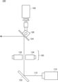
- 2 shows an example of a laser irradiation unit 120 and an imaging unit 130 in a simplified manner.
- 2 shows an example of a laser irradiation unit 120 and an imaging unit 130 in a simplified manner.
- 2 illustrates an example of a functional configuration of the detection device 100.
- 13 illustrates an example of a process flow performed by the detection device 100.
- 2 shows a schematic diagram of an example of detection of marine life 20 by a detection device 200 using radio waves 212 .
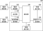
- 2 illustrates an example of a functional configuration of the detection device 200.
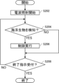
- 13 illustrates an example of a process flow performed by the detection device 200.
- 1 illustrates an example of a hardware configuration of a computer 1200 that functions as the detection device 100 or the detection device 200.
- the exploration device of this embodiment detects marine mammals, for example, by shining a laser toward the ocean surface and using a camera to detect the light that is scattered when it hits the steam.
- FIG. 1 shows a schematic example of detection of marine life 20 by a detection device 100 using a laser 112.
- the detection device 100 is mounted on a ship 10, for example, to detect marine life 20 around the ship 10.
- the detection device 100 may also be installed on a coast and used to detect marine life 20 around the coast.
- the detection device 100 detects the marine organism 20 by detecting the blowing 22 of the marine organism 20 using a laser 112.
- the marine organism 20 in this embodiment may be a marine mammal such as a whale or dolphin that blows the blowing 22.
- the detection device 100 captures the sea surface in a 360-degree direction around it while irradiating the laser 112 in that 360-degree direction.
- the detection device 100 captures the 360-degree direction by using one 360-degree camera or two 180-degree cameras, while rotating the irradiation direction of the laser 112 to continuously irradiate the laser 112 in a 360-degree direction.
- the detection device 100 may capture the sea surface in the irradiation direction of the laser 112 by rotating the shooting direction of the camera in synchronization with the rotation of the irradiation direction of the laser 112.
- the detection device 100 may determine that marine life 20 is present when it detects diffused light 114 from a laser 112 diffused by a jet 22 in an ocean surface image captured of the ocean surface. For example, when the detection device 100 determines that marine life 20 is present, it notifies the crew of the ship 10 of that fact.
- the monitoring of whales, dolphins, etc. has been based on visual confirmation, and has been performed by checking the blowout 22 with binoculars from the bridge of the ship 10 or the marine mammal monitoring room.
- the line of sight is about 17 km
- the area to be monitored is about 923 km2 , which places a very heavy burden on the monitor and also leads to the possibility of overlooking something.
- the detection device 100 can automate the monitoring of the marine life 20 and can perform monitoring at any time, which significantly reduces the monitoring burden and significantly reduces the possibility of overlooking the marine life 20.
- the detection device 100 may emit a laser 112 using the laser irradiation unit 120 and capture an image of the sea surface using the image capturing unit 130.
- the laser irradiation unit 120 includes a laser output unit 110, a reflecting mirror 122, a reflecting mirror 124, an angle adjustment screw 126, and a rotation motor 128.
- the laser 112 output by the laser output unit 110 is reflected by the reflecting mirrors 122 and 124 and irradiated toward the outside.
- the reflecting mirror 124 is rotated by the rotation motor 128, thereby changing the horizontal irradiation direction of the laser 112.
- the angle adjustment screw 126 changes the inclination of the reflecting mirror 124, thereby changing the vertical irradiation direction of the laser 112.
- the image capture unit 130 includes a 180-degree camera 132 and a 180-degree camera 134.
- the 180-degree camera 132 and the 180-degree camera 134 can capture images in a 360-degree direction.
- FIG. 4 shows an example of the functional configuration of the detection device 100.
- the detection device 100 includes a laser control unit 142, an image acquisition unit 144, a detection unit 146, a learning model storage unit 148, a learning execution unit 150, a control execution unit 152, and a determination unit 154.
- the detection device 100 includes all of these.
- the detection device 100 does not need to include the learning execution unit 150.
- the detection device 100 does not need to include the learning model storage unit 148.
- the detection device 100 does not need to include the determination unit 154.
- the detection device 100 may control the laser irradiation unit 120.
- the detection device 100 controls an external laser irradiation unit 120.
- the detection device 100 may be equipped with a laser irradiation unit 120.
- the detection device 100 may control the image capturing unit 130.
- the detection device 100 controls an external image capturing unit 130.
- the detection device 100 may be equipped with the image capturing unit 130.
- the laser irradiation unit 120 irradiates a laser.
- the laser irradiation unit 120 may be configured to be able to irradiate the laser in a 360-degree direction with the vertical direction as its axis.
- the laser irradiation unit 120 is configured to be able to rotate the laser irradiation direction with the vertical direction as its axis, and by continuously rotating the laser irradiation direction, the laser is irradiated in a 360-degree direction with the vertical direction as its axis.
- the laser irradiation unit 120 has multiple laser output units, and irradiates the laser in different directions simultaneously, thereby irradiating the laser in a 360-degree direction with the vertical direction as its axis.
- the laser irradiation unit 120 may be configured to be able to change the vertical irradiation direction of the laser.
- the laser irradiation unit 120 may be configured to be capable of emitting a sheet laser.
- the laser irradiation unit 120 may be capable of emitting a sheet laser that spreads in the vertical direction.
- the laser irradiation unit 120 may be configured to rotate the sheet laser that spreads in the vertical direction around an axis in the vertical direction.
- the laser irradiation unit 120 may be configured to emit the sheet laser that spreads in the vertical direction in different directions simultaneously.
- the laser irradiation unit 120 may be capable of emitting a sheet laser that spreads in the horizontal direction.
- the laser irradiation unit 120 may be configured to rotate the sheet laser that spreads in the horizontal direction around an axis in the vertical direction.
- the laser irradiation unit 120 may be configured to emit the sheet laser that spreads in the horizontal direction in different directions simultaneously.
- the laser irradiation unit 120 may be configured to change the vertical irradiation direction of the sheet laser that spreads in the horizontal direction.
- the photographing unit 130 photographs the ocean surface.
- the photographing unit 130 may be configured to be capable of photographing in a 360-degree direction with the vertical direction as its axis.
- the photographing unit 130 is, for example, configured with a 360-degree camera.
- the photographing unit 130 may also be configured with two 180-degree cameras.
- the photographing unit 130 may be configured to rotate a camera with a photographing range narrower than 360 degrees, thereby photographing in a 360-degree direction.
- the laser control unit 142 controls the laser irradiation unit 120 to irradiate the laser onto the sea surface.
- the laser control unit 142 causes the laser irradiation unit 120 to irradiate the laser onto the sea surface.
- the image acquisition unit 144 acquires an ocean surface image obtained by photographing the ocean surface.
- the image acquisition unit 144 may cause the photographing unit 130 to photograph the ocean surface and acquire the ocean surface image from the photographing unit 130.
- the detection unit 146 detects marine life 20 by the diffused light 114 of the laser 112 contained in the sea surface image acquired by the image acquisition unit 144. If the detection unit 146 determines that the sea surface image contains the diffused light 114 of the laser 112 diffused by the blowing gas 22 of the marine life 20, it may determine that the marine life 20 is present within the shooting range of the sea surface image. If the detection unit 146 determines that the diffused light 114 of the laser 112 diffused by the blowing gas 22 of the marine life 20 is located on the sea surface included in the sea surface image, it may determine that the marine life 20 is present within the shooting range of the sea surface image.
- the detection unit 146 may perform image analysis of the sea surface image to determine whether or not the sea surface image contains diffuse light 114 caused by the fumes 22.
- the detection unit 146 may determine whether or not the sea surface image contains diffuse light 114 caused by the fumes 22 by using, for example, a feature amount of diffuse light 114 of the laser 112 caused by the fumes 22 that has been registered in advance.
- the detection unit 146 may use machine learning technology.
- the learning model storage unit 148 stores a learning model that determines whether or not an input image contains the blow 22 of the marine organism 20, and that is generated by machine learning using an image including the diffused light 114 of the laser 112 diffused by the blow 22 of the marine organism 20 as learning data.
- the detection unit 146 may input the sea surface image acquired by the image acquisition unit 144 into the learning model stored in the learning model storage unit 148, thereby determining whether or not the marine organism 20 is present within the range of the sea surface image.
- the learning model storage unit 148 may store a learning model that is received from outside and generated by another device.
- the learning model storage unit 148 may store a learning model that is generated by the learning execution unit 150.
- the learning execution unit 150 may generate a learning model by collecting images that include the diffused light 114 of the laser 112 that is diffused by the blowing gas 22 of the marine organism 20, and performing machine learning using the collected images as learning data.
- the control execution unit 152 executes control according to the detection result of the detection unit 146.
- the control execution unit 152 executes notification control to control the detection unit 146 to notify a predetermined notification destination, such as a crew member of the ship 10, of the detection of marine life 20 by the detection unit 146.
- the notification to the notification destination may be performed by display output on a display of a device installed on the ship 10, audio output from a speaker of a device installed on the ship 10, display output on a display of a communication terminal carried by a crew member of the ship 10, audio output from a speaker of a communication terminal carried by a crew member of the ship 10, or the like.
- the control execution unit 152 may execute these notifications by transmitting notification information notifying that marine life 20 has been detected to a device installed on the ship 10 or a communication terminal carried by a crew member of the ship 10.
- the laser control unit 142 may, for example, control the laser irradiation unit 120 to irradiate the laser 112 in the traveling direction of the ship 10, and the image acquisition unit 144 may acquire a sea surface image of the sea surface in the traveling direction of the ship 10 captured by the image capture unit 130.
- the detection unit 146 may determine whether or not marine life 20 is present in the traveling direction of the ship 10 using the sea surface image of the sea surface in the traveling direction of the ship 10. If the detection unit 146 determines that marine life 20 is present in the traveling direction of the ship 10, the control execution unit 152 may execute notification control to control to notify a predetermined notification destination such as the crew of the ship 10.
- the control execution unit 152 may execute a traveling direction change control to change the traveling direction of the ship 10.
- the control execution unit 152 may execute a traveling speed change control to slow down the traveling speed of the ship 10.
- the control execution unit 152 may execute a traveling direction change control or a traveling speed change control by cooperating with the power unit of the ship 10.
- the laser control unit 142 may control the laser irradiation unit 120 to irradiate the laser 112 in multiple directions based on the detection device 100, and the photographing unit 130 may acquire one or multiple sea surface images obtained by photographing the sea surface in multiple directions based on the detection device 100.
- the laser control unit 142 may control the laser 112 to irradiate in multiple directions by rotating the irradiation direction of the laser 112.
- the photographing unit 130 may acquire sea surface images obtained by photographing the sea surface in all directions based on the detection device 100 using a 360-degree camera or two 180-degree cameras, or may acquire multiple sea surface images obtained by photographing the sea surface in multiple directions based on the detection device 100 by rotating a camera with a photographing range narrower than 360 degrees.
- the detection unit 146 may use the one or multiple sea surface images to determine whether or not marine life 20 is present in each of the multiple directions based on the detection device 100. This makes it possible to determine in which direction the marine organism 20 is located relative to the detection device 100.
- the detection unit 146 may detect the position of the marine life 20 relative to the detection device 100.
- the detection unit 146 may detect the position of the marine life 20 relative to the detection device 100 by using image analysis of ocean surface images or machine learning technology.
- the control execution unit 152 may execute control according to the position of the marine life 20.
- the control execution unit 152 executes notification control to notify the position of the marine life 20.
- the control execution unit 152 controls the ship 10 to change its traveling direction so as to avoid the position of the marine life 20.
- the control execution unit 152 controls the ship 10 to adjust its traveling speed according to the positional relationship between the ship 10 and the marine life 20.
- the laser irradiation unit 120 may be configured to be able to change the frequency of the laser 112 to be irradiated.
- the laser irradiation unit 120 may be configured to be able to irradiate lasers 112 of different frequencies, for example, by having a plurality of laser output units on the same axis, each of which outputs lasers 112 of different frequencies.
- the laser irradiation unit 120 may be configured to be able to irradiate lasers 112 of different frequencies, for example, by having laser output units capable of outputting lasers 112 of different frequencies.
- the photographing unit 130 may be configured to be able to perform photographing suitable for the frequency of the laser 112 emitted by the laser irradiation unit 120.
- the photographing unit 130 may be configured to be able to perform photographing suitable for the frequency of the laser 112, for example, by having multiple cameras on the same axis, each having sensitivity to different frequencies.
- the photographing unit 130 may be configured to be able to perform photographing suitable for the frequency of the laser 112, for example, by having multiple filters, each having characteristics for different frequencies.
- the appearance of the laser 112 varies depending on the weather, location (latitude and longitude), time of day, etc. For example, while there may be no problem on clear days, if the laser 112 is significantly attenuated in rainy weather and cuts off midway, this will have a negative impact on the detection of marine life 20.
- the frequency of the laser 112 to be changeable and the sensitivity of the imaging unit 130 to be changeable, it is possible to adjust the frequency of the laser 112 and the sensitivity of the imaging unit 130 to be suitable for the weather, location, time of day, etc., thereby reducing the possibility of an incident occurring in which the laser 112 is cut off midway.
- the determination unit 154 determines the frequency of the laser 112 emitted by the laser emission unit 120 based on at least one of the position information of the detection device 100, weather information at the position of the detection device 100, and time information.
- the laser control unit 142 causes the laser emission unit 120 to emit the laser 112 having the frequency determined by the determination unit 154. This makes it possible to automatically emit the laser 112 having a frequency suitable for the position of the detection device 100, the weather of the detection device 100, and the time of day, etc., thereby reducing the load of adjusting the frequency of the laser 112 and preventing a decrease in detection accuracy.
- the laser control unit 142 may control the image capture unit 130 so that, as the laser control unit 142 causes the laser irradiation unit 120 to irradiate the laser 112 having the frequency determined by the determination unit 154, the image acquisition unit 144 performs imaging suitable for that frequency. This can improve the accuracy with which the image capture unit 130 captures the laser 112 compared to a case in which the image capture unit 130 is not controlled, which can contribute to improving the accuracy of detection of marine life 20.
- the detection device 100 may have a GNSS (Global Navigation Satellite System) positioning function, and the determination unit 154 may acquire position information determined by the GNSS positioning function.
- the detection device 100 may acquire position information of the ship 10 from the ship 10, and handle the position information as the position information of the detection device 100.
- the detection device 100 may receive weather information for the detection device 100's position by satellite communication or the like from a weather information service that provides weather information for each position.
- the detection device 100 may acquire weather information measured by a weather radar mounted on the detection device 100 or the ship 10.
- the frequency of the laser 112 suitable for each weather may be determined in advance by conducting an experiment in which the laser 112 is irradiated while changing the frequency in each weather and the irradiated laser 112 is measured.
- the frequency of the laser 112 suitable for each location may be determined in advance by conducting an experiment in each location.
- the frequency of the laser 112 suitable for each time period may be determined in advance by conducting an experiment in each time period.
- the frequency of the laser 112 suitable for each weather and each location may be determined in advance by conducting an experiment in each time period in each weather in each location.
- the frequency of the laser 112 suitable for each weather and each time period may be determined in advance by conducting an experiment in each time period in each weather.
- the frequency of the laser 112 suitable for each weather, each location, and each time period may be determined in advance by conducting an experiment in each time period in each weather in each location.
- the frequency of the laser 112 suitable for each location and each time period may be determined in advance by conducting an experiment in each time period in each location.
- FIG. 5 shows an example of a processing flow by the detection device 100.
- the processing flow is described in which the detection device 100 searches for marine life 20 around the ship 10 and notifies the crew of the ship 10 when it detects marine life 20.
- step (sometimes abbreviated to S) 102 the image capture unit 130 starts capturing images of the ocean surface under the control of the image acquisition unit 144.
- step (104) the laser irradiation unit 120 starts irradiating the laser 112 under the control of the laser control unit 142.
- the detection unit 146 detects marine life 20 using the sea surface image acquired by the image acquisition unit 144. If the detection unit 146 determines that the sea surface image contains diffuse light 114 of the laser 112 diffused by the blowing gas 22 of the marine life 20, it may determine that the marine life 20 has been detected, and if it determines that the marine life 20 is not contained, it may determine that the marine life 20 has not been detected. If it is determined that the marine life 20 has been detected, the process proceeds to S108, and if it is determined that the marine life 20 has not been detected, the process proceeds to S110. In S108, the control execution unit 152 executes notification control for the crew of the ship 10.
- FIG. 6 shows a schematic example of detection of marine life 20 using radio waves 212 by a detection device 200.
- the detection device 200 is mounted on a ship 10, for example, to detect marine life 20 around the ship 10.
- the detection device 200 may also be installed on a coast and used to detect marine life 20 around the coast.
- the detection device 200 detects the marine organisms 20 by detecting the gas 22 of the marine organisms 20 using radio waves 212.
- the radio waves 212 may be millimeter waves or microwaves with a narrow emission direction.
- the detection device 200 captures the sea surface in a 360-degree direction around it while emitting radio waves 212 in that 360-degree direction.
- the detection device 200 captures the 360-degree direction by using one 360-degree camera or two 180-degree cameras, while rotating the direction of radiation of the radio waves 212 to continuously radiate the radio waves 212 in a 360-degree direction.
- the detection device 200 may capture the sea surface in the direction of radiation of the radio waves 212 by rotating the shooting direction of the camera in synchronization with the rotation of the radiation direction of the radio waves 212.
- the detection device 200 may determine that marine life 20 is present. For example, when the detection device 200 determines that marine life 20 is present, it notifies the crew of the ship 10 of that fact.
- FIG. 7 shows an example of the functional configuration of the detection device 200.
- the detection device 200 includes a radio wave control unit 242, a radio wave information acquisition unit 244, a detection unit 246, a learning model storage unit 248, a learning execution unit 250, a control execution unit 252, and a determination unit 254.
- the detection device 200 includes all of these.
- the detection device 200 does not need to include the learning execution unit 250.
- the detection device 200 does not need to include the learning model storage unit 248.
- the detection device 200 does not need to include the determination unit 254.
- the detection device 200 may control the radio wave irradiation unit 220.
- the detection device 200 controls an external radio wave irradiation unit 220.
- the detection device 200 may be equipped with the radio wave irradiation unit 220.
- the detection device 200 may control the radio wave receiving unit 230.
- the detection device 200 controls an external radio wave receiving unit 230.
- the detection device 200 may be equipped with a radio wave receiving unit 230.
- the radio wave irradiation unit 220 irradiates radio waves.
- the radio wave irradiation unit 220 may irradiate millimeter waves with a narrowed emission direction.
- the radio wave irradiation unit 220 may irradiate microwaves with a narrowed emission direction.
- the radio wave irradiation unit 220 may be configured to be able to irradiate radio waves in 360-degree directions with the vertical direction as its axis.
- the radio wave irradiation unit 220 is configured to be able to rotate the irradiation direction of the radio waves with the vertical direction as its axis, and irradiates radio waves in 360-degree directions with the vertical direction as its axis by continuously rotating the irradiation direction of the radio waves.
- the radio wave irradiation unit 220 has multiple radio wave output units, and irradiates radio waves in different directions at the same time, thereby irradiating radio waves in 360-degree directions with the vertical direction as its axis.
- the radio wave irradiation unit 220 may be configured to be able to change the irradiation direction of the radio waves in the vertical direction.
- the radio wave receiving unit 230 receives radio waves.
- the radio wave receiving unit 230 may be configured to be able to receive radio waves from 360 degrees around the vertical axis.
- the radio wave receiving unit 230 may have multiple antennas arranged to receive radio waves from 360 degrees.
- the radio wave receiving unit 230 may have one or multiple antennas configured to rotate around the vertical axis.
- the radio wave control unit 242 controls the irradiation of radio waves onto the sea surface.
- the radio wave control unit 242 causes the radio wave irradiation unit 220 to irradiate radio waves onto the sea surface.
- the radio wave information acquisition unit 244 acquires information on reflected radio waves that are radio waves reflected by the radio wave irradiation unit 220.
- the radio wave information acquisition unit 244 may acquire information on the reflected radio waves received by the radio wave receiving unit 230 from the radio wave receiving unit 230.
- the information on the reflected radio waves may include the dielectric constant.
- the detection unit 246 detects marine life 20 based on the information acquired by the radio wave information acquisition unit 244.
- the detection unit 246 may detect marine life 20 based on the dielectric constant of the reflected radio waves.
- the detection unit 246 may detect marine life 20 based on the difference between the dielectric constant of the radio waves irradiated by the radio wave irradiating unit 220 under the control of the radio wave control unit 242 and the dielectric constant of the reflected radio waves.
- the detection unit 246 may, for example, preregister the difference between the dielectric constant of the irradiated radio waves and the dielectric constant of the reflected radio waves, which is determined by performing an experiment in which radio waves are irradiated from the radio wave irradiating unit 220 toward the blowing gas 22 of the marine organism 20 and the reflected radio waves are analyzed, and may use the registered information to detect the marine organism 20 under the control of the radio wave control unit 242 from the difference between the dielectric constant of the radio waves irradiated by the radio wave irradiating unit 220 and the dielectric constant of the reflected radio waves.
- the detection unit 246 may use machine learning technology.
- the learning model storage unit 248 stores a learning model that irradiates radio waves 212 to the gas 22 of the marine organism 20, and determines whether the dielectric constant of the input irradiated radio waves and the dielectric constant of the reflected radio waves are reflected by the gas 22, the learning model being generated by machine learning using information on the reflected radio waves received by the radio wave receiving unit 230 and information on the irradiated radio waves 212 as learning data.
- the detection unit 246 may determine whether the marine organism 20 is present by inputting information on the radio waves 212 irradiated by the radio wave irradiating unit 220 and information on the reflected radio waves 214 received by the radio wave receiving unit 230 into the learning model stored in the learning model storage unit 248.
- the learning model storage unit 248 may store a learning model that is received from the outside and generated by another device.
- the learning model storage unit 248 may store a learning model that is generated by the learning execution unit 250.
- the learning execution unit 250 may generate a learning model by collecting information on the radio waves 212 and the reflected radio waves 214 that are generated when the radio waves 212 are reflected by the gas 22 of the marine organism 20, and performing machine learning using the collected information as learning data.
- the control execution unit 252 executes control according to the detection result of the detection unit 246. For example, the control execution unit 252 executes notification control such that when marine life 20 is detected by the detection unit 246, a notification of that fact is sent to a predetermined notification destination such as the crew of the ship 10.
- the control execution unit 252 may execute notification control similar to that of the control execution unit 152.
- the radio wave control unit 242 may, for example, control the radio wave emission unit 220 to emit radio waves 212 in the traveling direction of the ship 10.
- the detection unit 246 may determine whether or not marine life 20 is present in the traveling direction of the ship 10. If the detection unit 246 determines that marine life 20 is present in the traveling direction of the ship 10, the control execution unit 252 may execute notification control, traveling direction change control, and traveling speed change control similar to the control execution unit 152.
- the radio wave control unit 242 may control the radio wave emitting unit 220 to emit radio waves 212 in multiple directions based on the detection device 200, and the radio wave receiving unit 230 may receive radio waves in multiple directions based on the detection device 100.
- the radio wave control unit 242 may control the radio waves 212 to be emitted in multiple directions by rotating the emission direction of the radio waves 212.
- the radio wave receiving unit 230 may receive radio waves in all directions based on the detection device 100 by using multiple antennas or rotating the antennas.
- the detection unit 246 may determine whether or not marine life 20 is present in each of the multiple directions based on the detection device 200.
- the detection unit 246 may detect the position of the marine life 20 relative to the detection device 200.
- the detection unit 246 may detect the position of the marine life 20 relative to the detection device 200 by using the direction of irradiation of the radio waves 212 and the time from emitting the radio waves 212 to receiving the reflected radio waves 214, etc.
- the control execution unit 252 may execute control according to the position of the marine life 20.
- the control execution unit 252 executes notification control to notify the position of the marine life 20.
- the control execution unit 252 controls the ship 10 to change its traveling direction so as to avoid the position of the marine life 20.
- the control execution unit 252 controls the ship 10 to adjust its traveling speed according to the positional relationship between the ship 10 and the marine life 20.
- the radio wave irradiation unit 220 may be configured to be able to change the frequency of the radio waves it irradiates.
- the radio wave irradiation unit 220 may be configured to be able to irradiate radio waves 212 of different frequencies, for example, by having multiple radio wave output units on the same axis, each of which outputs radio waves 212 of a different frequency.
- the radio wave irradiation unit 220 may be configured to be able to irradiate radio waves 212 of different frequencies, for example, by having radio wave output units capable of outputting radio waves 212 of different frequencies.
- the determination unit 254 determines the frequency of the radio waves to be emitted by the radio wave emission unit 220 based on at least one of the location information of the detection device 200, the weather information at the location of the detection device 200, and the time information. The determination unit 254 may determine the frequency in the same manner as the determination unit 154.
- the radio wave control unit 242 causes the radio wave emission unit 220 to emit radio waves 212 of the frequency determined by the determination unit 254.
- FIG. 8 shows an example of a processing flow by the detection device 200.
- the processing flow is described in which the detection device 200 searches for marine life 20 around the ship 10 and notifies the crew of the ship 10 when it detects marine life 20.
- the radio wave irradiation unit 220 starts emitting radio waves 212.
- the detection unit 246 detects marine life 20 using the radio wave information acquired by the radio wave information acquisition unit 244. The detection unit 246 may determine that marine life 20 has been detected if the difference in dielectric constant between the radio waves 212 and the reflected radio waves 214 satisfies a condition, and may determine that marine life 20 has not been detected if the condition is not satisfied. If it is determined that marine life 20 has been detected, the process proceeds to S206, and if it is determined that marine life 20 has not been detected, the process proceeds to S208. In S206, the control execution unit 252 executes notification control for the crew of the ship 10.
- FIG. 9 shows a schematic diagram of an example of a hardware configuration of a computer 1200 functioning as the detection device 100 or the detection device 200.
- a program installed on the computer 1200 can cause the computer 1200 to function as one or more "parts" of the device according to the present embodiment, or to execute operations or one or more "parts” associated with the device according to the present embodiment, and/or to execute a process or steps of the process according to the present embodiment.
- Such a program can be executed by the CPU 1212 to cause the computer 1200 to execute specific operations associated with some or all of the blocks of the flowcharts and block diagrams described herein.
- the computer 1200 includes a CPU 1212, a RAM 1214, and a graphics controller 1216, which are connected to each other by a host controller 1210.
- the computer 1200 also includes input/output units such as a communication interface 1222, a storage device 1224, a DVD drive 1226, and an IC card drive, which are connected to the host controller 1210 via an input/output controller 1220.
- the DVD drive 1226 may be a DVD-ROM drive, a DVD-RAM drive, or the like.
- the storage device 1224 may be a hard disk drive, a solid state drive, or the like.
- the computer 1200 also includes a ROM 1230 and a legacy input/output unit such as a keyboard, which are connected to the input/output controller 1220 via an input/output chip 1240.
- the CPU 1212 operates according to the programs stored in the ROM 1230 and the RAM 1214, thereby controlling each unit.
- the graphics controller 1216 acquires image data generated by the CPU 1212 into a frame buffer or the like provided in the RAM 1214 or into itself, and causes the image data to be displayed on the display device 1218.
- the communication interface 1222 communicates with other electronic devices via a network.
- the storage device 1224 stores programs and data used by the CPU 1212 in the computer 1200.
- the DVD drive 1226 reads programs or data from a DVD-ROM 1227 or the like and provides the programs or data to the storage device 1224.
- the IC card drive reads programs and data from an IC card and/or writes programs and data to an IC card.
- ROM 1230 stores therein a boot program or the like to be executed by computer 1200 upon activation, and/or a program that depends on the hardware of computer 1200.
- I/O chip 1240 may also connect various I/O units to I/O controller 1220 via USB ports, parallel ports, serial ports, keyboard ports, mouse ports, etc.
- the programs are provided by a computer-readable storage medium such as a DVD-ROM 1227 or an IC card.
- the programs are read from the computer-readable storage medium, installed in the storage device 1224, RAM 1214, or ROM 1230, which are also examples of computer-readable storage media, and executed by the CPU 1212.
- the information processing described in these programs is read by the computer 1200, and brings about cooperation between the programs and the various types of hardware resources described above.
- An apparatus or method may be constructed by realizing the operation or processing of information according to the use of the computer 1200.
- CPU 1212 may execute a communication program loaded into RAM 1214 and instruct communication interface 1222 to perform communication processing based on the processing described in the communication program.
- communication interface 1222 reads transmission data stored in a transmission buffer area provided in RAM 1214, storage device 1224, DVD-ROM 1227, or a recording medium such as an IC card, and transmits the read transmission data to the network, or writes received data received from the network to a reception buffer area or the like provided on the recording medium.
- the CPU 1212 may also cause all or a necessary portion of a file or database stored in an external recording medium such as the storage device 1224, DVD drive 1226 (DVD-ROM 1227), IC card, etc. to be read into the RAM 1214, and perform various types of processing on the data on the RAM 1214. The CPU 1212 may then write back the processed data to the external recording medium.
- an external recording medium such as the storage device 1224, DVD drive 1226 (DVD-ROM 1227), IC card, etc.
- CPU 1212 may perform various types of processing on data read from RAM 1214, including various types of operations, information processing, conditional judgment, conditional branching, unconditional branching, information search/replacement, etc., as described throughout this disclosure and specified by the instruction sequence of the program, and write back the results to RAM 1214.
- CPU 1212 may also search for information in a file, database, etc. in the recording medium.
- CPU 1212 may search for an entry whose attribute value of the first attribute matches a specified condition from among the multiple entries, read the attribute value of the second attribute stored in the entry, and thereby obtain the attribute value of the second attribute associated with the first attribute that satisfies a predetermined condition.
- the above-described programs or software modules may be stored in a computer-readable storage medium on the computer 1200 or in the vicinity of the computer 1200.
- a recording medium such as a hard disk or RAM provided in a server system connected to a dedicated communication network or the Internet can be used as a computer-readable storage medium, thereby providing the programs to the computer 1200 via the network.
- the blocks in the flowcharts and block diagrams in this embodiment may represent stages of a process where an operation is performed or "parts" of a device responsible for performing the operation. Particular stages and “parts" may be implemented by dedicated circuitry, programmable circuitry provided with computer-readable instructions stored on a computer-readable storage medium, and/or a processor provided with computer-readable instructions stored on a computer-readable storage medium.
- the dedicated circuitry may include digital and/or analog hardware circuitry and may include integrated circuits (ICs) and/or discrete circuits.
- the programmable circuitry may include reconfigurable hardware circuitry including AND, OR, XOR, NAND, NOR, and other logical operations, flip-flops, registers, and memory elements, such as, for example, field programmable gate arrays (FPGAs) and programmable logic arrays (PLAs).
- FPGAs field programmable gate arrays
- PDAs programmable logic arrays
- a computer-readable storage medium may include any tangible device capable of storing instructions that are executed by a suitable device, such that a computer-readable storage medium having instructions stored thereon comprises an article of manufacture that includes instructions that can be executed to create means for performing the operations specified in the flowchart or block diagram.
- Examples of computer-readable storage media may include electronic storage media, magnetic storage media, optical storage media, electromagnetic storage media, semiconductor storage media, and the like.
- Computer-readable storage media may include floppy disks, diskettes, hard disks, random access memories (RAMs), read-only memories (ROMs), erasable programmable read-only memories (EPROMs or flash memories), electrically erasable programmable read-only memories (EEPROMs), static random access memories (SRAMs), compact disk read-only memories (CD-ROMs), digital versatile disks (DVDs), Blu-ray disks, memory sticks, integrated circuit cards, and the like.
- RAMs random access memories
- ROMs read-only memories
- EPROMs or flash memories erasable programmable read-only memories
- EEPROMs electrically erasable programmable read-only memories
- SRAMs static random access memories
- CD-ROMs compact disk read-only memories
- DVDs digital versatile disks
- Blu-ray disks memory sticks, integrated circuit cards, and the like.
- the computer readable instructions may include either assembler instructions, instruction set architecture (ISA) instructions, machine instructions, machine-dependent instructions, microcode, firmware instructions, state setting data, or source or object code written in any combination of one or more programming languages, including object-oriented programming languages such as Smalltalk (registered trademark), JAVA (registered trademark), C++, etc., and conventional procedural programming languages such as the "C" programming language or similar programming languages.
- ISA instruction set architecture
- machine instructions machine-dependent instructions
- microcode firmware instructions
- state setting data or source or object code written in any combination of one or more programming languages, including object-oriented programming languages such as Smalltalk (registered trademark), JAVA (registered trademark), C++, etc., and conventional procedural programming languages such as the "C" programming language or similar programming languages.
- the computer-readable instructions may be provided to a processor of a general-purpose computer, special-purpose computer, or other programmable data processing apparatus, or to a programmable circuit, either locally or over a local area network (LAN), a wide area network (WAN) such as the Internet, so that the processor of the general-purpose computer, special-purpose computer, or other programmable data processing apparatus, or to a programmable circuit, executes the computer-readable instructions to generate means for performing the operations specified in the flowcharts or block diagrams.
- processors include computer processors, processing units, microprocessors, digital signal processors, controllers, microcontrollers, etc.
Landscapes
- Remote Sensing (AREA)
- Engineering & Computer Science (AREA)
- Physics & Mathematics (AREA)
- Radar, Positioning & Navigation (AREA)
- General Physics & Mathematics (AREA)
- Life Sciences & Earth Sciences (AREA)
- Geophysics (AREA)
- General Life Sciences & Earth Sciences (AREA)
- Computer Networks & Wireless Communication (AREA)
- Electromagnetism (AREA)
- Environmental & Geological Engineering (AREA)
- Geology (AREA)
- Geophysics And Detection Of Objects (AREA)
Abstract
海面に対してレーザを照射するよう制御するレーザ制御部と、前記海面を撮影した海面画像を取得する画像取得部と、前記海面画像に含まれる前記レーザの拡散光によって海洋生物を検知する検知部とを備える検知装置を提供する。海面に対して電波を照射するよう制御する電波制御部と、前記電波が反射された反射電波の情報を取得する電波情報取得部と、前記反射電波の誘電率によって海洋生物を検知する検知部とを備える検知装置を提供する。
Description
本発明は、検知装置及びプログラムに関する。
特許文献1には、エアガン等の振源から水中に向けて発振され海底で反射した音波に基づいて海底地質(海底構造)を探査するための海底地質探査システムについて記載されている。
[先行技術文献]
[特許文献]
[特許文献1]特開2018-185206号公報
[先行技術文献]
[特許文献]
[特許文献1]特開2018-185206号公報
本発明の一実施態様によれば、検知装置が提供される。前記検知装置は、海面に対してレーザを照射するよう制御するレーザ制御部を備えてよい。前記検知装置は、前記海面を撮影した海面画像を取得する画像取得部を備えてよい。前記検知装置は、前記海面画像に含まれる前記レーザの拡散光によって海洋生物を検知する検知部を備えてよい。
前記検知装置において、前記検知部は、前記海面画像に含まれる海面上に、前記海洋生物の噴気によって拡散された前記レーザの前記拡散光が位置する場合に、前記海洋画像の撮影範囲内に前記海洋生物が存在すると判定してよい。前記検知装置は、海洋生物の噴気によって拡散されたレーザの拡散光を含む画像を学習データとして用いた機械学習によって生成された、入力された画像に海洋生物の噴気が含まれるか否かを判定する学習モデルを記憶する学習モデル記憶部を備えてよく、前記検知部は、前記海面画像を前記学習モデルに入力することによって、前記画像の範囲内に海洋生物が存在するか否かを判定してよい。
前記いずれかの検知装置において、前記レーザ制御部は、前記検知装置を基準とした複数の方向に前記レーザを照射するよう制御してよく、前記画像取得部は、前記検知装置を基準とした複数の方向の前記海面を撮影した複数の海面画像を取得してよく、前記検知部は、前記複数の海面画像を用いて、前記検知装置を基準とした複数の方向のそれぞれに、前記海洋生物が存在するか否かを判定してよい。前記検知部は、前記検知装置を基準とした前記海洋生物の位置を検知してよく、前記検知装置は、前記検知部が前記海洋生物を検知した場合に、前記海洋生物の位置に応じた制御を実行する制御実行部を備えてよい。前記制御実行部は、前記海洋生物の位置を通知する通知制御を実行してよい。前記制御装置は、船に搭載されてよく、前記制御実行部は、前記海洋生物の位置を避けるように前記船の進行方向を変更するよう制御してよい。前記制御実行部は、前記船と前記海洋生物との位置関係に応じて、前記船の進行速度を調整するよう制御してよい。
前記いずれかの検知装置は、前記レーザを照射するレーザ照射部と、前記海面を撮影する撮像部とを備えてよく、前記レーザ照射部は、照射する前記レーザの周波数を変更可能に構成されていてよく、前記撮像部は、前記レーザ照射部が照射する前記レーザの周波数に適した撮影を実行可能に構成されていてよい。前記撮影部は、同軸上に、それぞれが異なる周波数に対する感度を有する複数のカメラを備えることによって、前記レーザの周波数に適した撮影を実行可能に構成されてよい。前記撮影部は、それぞれが異なる周波数に対する特性を有する複数のフィルタを備えることによって、前記レーザの周波数に適した撮影を実行可能に構成されてよい。前記検知装置は、前記検知装置の位置情報、前記検知装置の位置の天候情報、及び前記海面画像を撮影した撮影時刻情報の少なくともいずれかに基づいて、前記レーザ照射部が照射する前記レーザの周波数を決定する決定部を備えてよく、前記レーザ制御部は、前記決定部によって決定された周波数の前記レーザを前記レーザ照射部に照射させてよい。前記レーザ制御部が、前記決定部によって決定された周波数のレーザを前記レーザ照射部に照射させることにともなって、前記画像取得部が、当該周波数に適した撮影を実行するように、前記撮影部を制御してよい。
本発明の一実施態様によれば、コンピュータを、前記検知装置として機能させるためのプログラムが提供される。前記プログラムは、前記検知装置を、海面に対してレーザを照射するよう制御するレーザ制御部として機能させるためのプログラムであってよい。前記プログラムは、前記コンピュータを、前記海面を撮影した海面画像を取得する画像取得部として機能させるためのプログラムであってよい。前記プログラムは、前記コンピュータを、前記海面画像に含まれる前記レーザの拡散光によって海洋生物を検知する検知部として機能させるためのプログラムであってよい。
本発明の一実施態様によれば、検知装置が提供される。前記検知装置は、海面に対して電波を照射するよう制御する電波制御部を備えてよい。前記検知装置は、前記電波が反射された反射電波の情報を取得する電波情報取得部を備えてよい。前記検知装置は、前記反射電波の誘電率によって海洋生物を検知する検知部を備えてよい。
前記検知装置において、前記検知部は、前記電波制御部の制御のもと照射された前記電波の誘電率と、前記反射電波の誘電率との差異に基づいて、前記海洋生物を検知してよい。前記検知装置は、前記電波を照射する電波照射部と、前記反射電波を受信する電波受信部とを備えてよく、前記電波照射部は、照射する電波の周波数を変更可能に構成されていてよい。
本発明の一実施態様によれば、コンピュータを、前記検知装置として機能させるためのプログラムが提供される。前記プログラムは、前記コンピュータを、海面に対して電波を照射するよう制御する電波制御部として機能させるためのプログラムであってよい。前記プログラムは、前記コンピュータを、前記電波が反射された反射電波の情報を取得する電波情報取得部として機能させるためのプログラムであってよい。前記プログラムは、前記コンピュータを、前記反射電波の誘電率によって海洋生物を検知する検知部として機能させるためのプログラムであってよい。
なお、上記の発明の概要は、本発明の必要な特徴の全てを列挙したものではない。また、これらの特徴群のサブコンビネーションもまた、発明となりうる。
水中での音波の発信は海洋生物、特にクジラ、イルカ等の海棲哺乳類に対して悪い影響を及ぼすことから、海底地質探査システムの稼働中は、海棲哺乳類の監視が義務付けられており、目視での監視が行われていた。しかしながら、目視での監視は常時監視員を配置する必要があるほか、見逃し等のおそれもあり効率的でなかった。それに対して、本実施形態に係る探査装置は、例えば、海面に向けてレーザを照射し、噴気に当たって拡散した光をカメラで検知すること等によって、海棲哺乳類の検知を行う。
以下、発明の実施の形態を通じて本発明を説明するが、以下の実施形態は請求の範囲にかかる発明を限定するものではない。また、実施形態の中で説明されている特徴の組み合わせの全てが発明の解決手段に必須であるとは限らない。
図1は、検知装置100によるレーザ112を用いた海洋生物20の検知の一例を概略的に示す。検知装置100は、例えば、船10に搭載されて、船10の周辺の海洋生物20を検知する。検知装置100は、海岸に設置されて、海岸周辺の海洋生物20を検知する等の用いられ方をしてもよい。
検知装置100は、レーザ112によって、海洋生物20の噴気22を検知することによって、海洋生物20を検知する。本実施形態に係る海洋生物20は、噴気22を行うクジラ及びイルカ等の海棲哺乳類であってよい。
例えば、検知装置100は、周辺360度方向の海面を撮影しつつ、当該360度方向にレーザ112を照射する。具体例として、検知装置100は、1つの360度カメラを用いたり、2つの180度カメラを用いたりすることによって360度方向を撮影しつつ、レーザ112の照射方向を回転させることによって360度方向に連続的にレーザ112を照射する。検知装置100は、レーザ112の照射方向の回転と同期させてカメラの撮影方向を回転させることによって、レーザ112の照射方向の海面を撮影してもよい。
検知装置100は、海面を撮影した海面画像によって、噴気22によって拡散されたレーザ112の拡散光114を検出した場合に、海洋生物20が存在すると判定してよい。検知装置100は、例えば、海洋生物20が存在すると判定した場合に、船10の乗組員に対して、その旨を通知する。
従来は、クジラやイルカ等の監視の基本は目視確認であり、船10のブリッジ又は海棲哺乳類監視室等から双眼鏡で噴気22を確認することによって行われていた。しかし、例えば、海面から20mの高さから監視した場合の見通し距離は約17kmであり、監視する広さとしては約923km2であり、監視員の負荷は非常に高く、また、見落としの可能性もあった。それに対して本実施形態に係る検知装置100によれば、海洋生物20の監視を自動化できるとともに、監視を常時行うことができるので、監視の負荷を大幅に軽減できるとともに、海洋生物20の見落としの可能性を大幅に低減することができる。
図2及び図3は、レーザ照射部120及び撮影部130の一例を概略的に示す。検知装置100は、レーザ照射部120によってレーザ112を照射し、撮影部130によって海面を撮影してよい。
図2及び図3に示す例において、レーザ照射部120は、レーザ出力部110、反射ミラー122、反射ミラー124、角度調整ネジ126、及び回転モータ128を備える。レーザ照射部120において、レーザ出力部110が出力したレーザ112が、反射ミラー122と反射ミラー124とによって反射されて、外部に向けて照射される。回転モータ128によって反射ミラー124が回転することによって、レーザ112の横方向の照射方向が変わる。角度調整ネジ126によって、反射ミラー124の傾きが変わることによって、レーザ112の上下方向の照射方向が変わる。
図2及び図3に示す例において、撮影部130は、180度カメラ132と、180度カメラ134とを備える。180度カメラ132及び180度カメラ134によって、360度の方向を撮影することができる。
図2及び図3に示す構成は一例であって、レーザ照射部120及び撮影部130は、他の構成であってもよい。
図4は、検知装置100の機能構成の一例を概略的に示す。検知装置100は、レーザ制御部142、画像取得部144、検知部146、学習モデル記憶部148、学習実行部150、制御実行部152、及び決定部154を備える。
検知装置100がこれらの全てを備えることは必須とは限らない。例えば、検知装置100は、学習実行部150を備えなくてもよい。例えば、検知装置100は、学習モデル記憶部148を備えなくてもよい。例えば、検知装置100は、決定部154を備えなくてもよい。
検知装置100は、レーザ照射部120を制御してよい。例えば、検知装置100は、外付けのレーザ照射部120を制御する。検知装置100は、レーザ照射部120を備えてもよい。
検知装置100は、撮影部130を制御してよい。例えば、検知装置100は、外付けの撮影部130を制御する。検知装置100は、撮影部130を備えてもよい。
レーザ照射部120は、レーザを照射する。レーザ照射部120は、レーザを、上下方向を軸とした360度方向に照射可能に構成されていてよい。例えば、レーザ照射部120は、レーザの照射方向を、上下方向を軸として回転可能に構成されており、レーザの照射方向を連続的に回転させることによって、上下方向を軸とした360度方向にレーザを照射する。例えば、レーザ照射部120は、複数のレーザ出力部を有することによって、同時に異なる方向にレーザを照射することによって、上下方向を軸とした360度方向にレーザを照射する。レーザ照射部120は、レーザの上下方向の照射方向を変更可能に構成されていてよい。
レーザ照射部120は、シートレーザを照射可能に構成されてもよい。レーザ照射部120は、上下方向に広がるシートレーザを照射可能であってよい。レーザ照射部120は、上下方向に広がるシートレーザを、上下方向を軸として回転可能に構成されていてよい。レーザ照射部120は、上下方向に広がるシートレーザを同時に異なる方向に照射可能に構成されてもよい。レーザ照射部120は、横方向に広がるシートレーザを照射可能であってよい。レーザ照射部120は、横方向に広がるシートレーザを、上下方向を軸として回転可能に構成されていてよい。レーザ照射部120は、横方向に広がるシートレーザを同時に異なる方向に照射可能に構成されてもよい。レーザ照射部120は、横方向に広がるシートレーザの上下方向の照射方向を変更可能に構成されていてよい。
撮影部130は、海面を撮影する。撮影部130は、上下方向を軸とした360度方向を撮影可能に構成されていてよい。撮影部130は、例えば、360度カメラによって構成される。撮影部130は、2つの180度カメラによって構成されてもよい。撮影部130は、360度よりも撮影範囲が狭いカメラを回転する構成を備えることによって、360度方向を撮影してもよい。
レーザ制御部142は、海面に対してレーザを照射するよう制御する。レーザ制御部142は、レーザ照射部120に、海面に対してレーザを照射させる。
画像取得部144は、海面を撮影した海面画像を取得する。画像取得部144は、撮影部130に海面を撮影させて、撮影部130から海面画像を取得してよい。
検知部146は、画像取得部144が取得した海面画像に含まれるレーザ112の拡散光114によって海洋生物20を検知する。検知部146は、海面画像に、海洋生物20の噴気22によって拡散されたレーザ112の拡散光114が含まれると判定した場合、海面画像の撮影範囲内に海洋生物20が存在すると判定してよい。検知部146は、海面画像に含まれる海面上に、海洋生物20の噴気22によって拡散されたレーザ112の拡散光114が位置すると判定した場合に、海面画像の撮影範囲内に海洋生物20が存在すると判定してよい。
検知部146は、海面画像を画像解析することによって、海面画像に、噴気22による拡散光114が含まれるか否かを判定してよい。検知部146は、例えば、予め登録された、噴気22によるレーザ112の拡散光114の特徴量を用いて、海面画像に噴気22による拡散光114が含まれるか否かを判定する。
検知部146は、機械学習技術を用いてもよい。学習モデル記憶部148は、海洋生物20の噴気22によって拡散されたレーザ112の拡散光114を含む画像を学習データとして用いた機械学習によって生成された、入力された画像に海洋生物20の噴気22が含まれるか否かを判定する学習モデルを記憶する。検知部146は、画像取得部144が取得した海面画像を、学習モデル記憶部148に記憶されている学習モデルに入力することによって、当該海面画像の範囲内に海洋生物20が存在するか否かを判定してよい。
学習モデル記憶部148は、外部から受信した、他の装置によって生成された学習モデルを記憶してよい。学習モデル記憶部148は、学習実行部150によって生成された学習モデルを記憶してもよい。学習実行部150は、海洋生物20の噴気22によって拡散されたレーザ112の拡散光114を含む画像を収集して、収集した画像を学習データとして用いた機械学習を実行することによって、学習モデルを生成してよい。
制御実行部152は、検知部146の検知結果に応じた制御を実行する。例えば、制御実行部152は、検知部146によって海洋生物20が検知された場合に、その旨を、船10の乗組員等の予め定められた通知先に通知するよう制御する通知制御を実行する。通知先への通知は、船10に設置された装置のディスプレイによる表示出力、船10に設置された装置のスピーカによる音声出力、船10の乗組員が所持する通信端末のディスプレイによる表示出力、船10の乗組員が所持する通信端末のスピーカによる音声出力等によって行われてよい。制御実行部152は、海洋生物20が検知されたことを通知する通知情報を、船10に設置された装置や、船10の乗組員が所持する通信端末に送信することによって、これらの通知を実行させてよい。
レーザ制御部142は、例えば、船10の進行方向にレーザ112を照射するようにレーザ照射部120を制御してよく、画像取得部144は、撮影部130によって撮影された、船10の進行方向の海面を撮影した海面画像を取得してよい。検知部146は、船10の進行方向の海面を撮影した海面画像を用いて、船10の進行方向に海洋生物20が存在するか否かを判定してよい。検知部146が、船10の進行方向に海洋生物20が存在すると判定した場合、制御実行部152は、船10の乗組員等の予め定められた通知先に通知するよう制御する通知制御を実行してよい。制御実行部152は、船10の進行方向を変更する進行方向変更制御を実行してもよい。制御実行部152は、船10の進行速度を遅くさせる進行速度変更制御を実行してもよい。制御実行部152は、船10の動力部と連携することによって、進行方向変更制御や、進行速度変更制御を実行してよい。
レーザ制御部142は、検知装置100を基準とした複数の方向にレーザ112を照射するようにレーザ照射部120を制御してよく、撮影部130は、検知装置100を基準とした複数の方向の海面を撮影した1又は複数の海面画像を取得してよい。レーザ制御部142は、レーザ112の照射方向を回転させることによって、複数の方向にレーザ112を照射するように制御してよい。撮影部130は、360度カメラ又は2つの180度カメラによって、検知装置100を基準とした全方向の海面を撮影した海面画像を取得したり、撮影範囲が360度より狭いカメラを回転させることによって、検知装置100を基準とした複数の方向の海面を撮影した複数の海面画像を取得してよい。検知部146は、当該1又は複数の海面画像を用いて、検知装置100を基準とした複数の方向のそれぞれに、海洋生物20が存在するか否かを判定してよい。これにより、検知装置100を基準としたいずれの方向に海洋生物20が存在するかを把握可能にできる。
検知部146は、検知装置100を基準とした海洋生物20の位置を検知してもよい。検知部146は、海面画像の画像解析や、機械学習技術を用いることによって、検知装置100を基準とした海洋生物20の位置を検知してよい。検知部146が海洋生物20の位置を検知した場合、制御実行部152は、海洋生物20の位置に応じた制御を実行してよい。例えば、制御実行部152は、海洋生物20の位置を通知する通知制御を実行する。例えば、制御実行部152は、海洋生物20の位置を避けるように船10の進行方向を変更するよう制御する。例えば、制御実行部152は、船10と海洋生物20との位置関係に応じて、船10の進行速度を調整するよう制御する。
レーザ照射部120は、照射するレーザ112の周波数を変更可能に構成されていてもよい。レーザ照射部120は、例えば、同軸上に、それぞれが異なる周波数のレーザ112を出力する複数のレーザ出力部を備えることによって、異なる周波数のレーザ112を照射可能に構成されてよい。レーザ照射部120は、例えば、異なる周波数のレーザ112を出力可能なレーザ出力部を備えることによって、異なる周波数のレーザ112を照射可能に構成されてもよい。
撮影部130は、レーザ照射部120が照射するレーザ112の周波数に適した撮影を実行可能に構成されていてもよい。撮影部130は、例えば、同軸上に、それぞれが異なる周波数に対する感度を有する複数のカメラを備えることによって、レーザ112の周波数に適した撮影を実行可能に構成されてよい。撮影部130は、例えば、それぞれが異なる周波数に対する特性を有する複数のフィルタを備えることによって、レーザ112の周波数に適した撮影を実行可能に構成されてよい。
レーザ112は、天候、位置(緯度・経度)、及び時間帯等によって、見え方が異なる。例えば、晴天時には問題なくても、雨天時には減衰が大きくなって途中で途絶えてしまう、といった事態が発生すると、海洋生物20の検知に悪影響を及ぼす。それに対して、レーザ112の周波数を変更可能に構成し、撮影部130の感度を変更可能に構成することによって、天候、位置、時間帯等に適したレーザ112の周波数及び撮影部130の感度に調整することを可能にでき、レーザ112が途中で途絶える等の事態が発生する可能性を低減することができる。
決定部154は、検知装置100の位置情報、検知装置100の位置の天候情報、及び時刻情報の少なくともいずれかに基づいて、レーザ照射部120が照射するレーザ112の周波数を決定する。レーザ制御部142は、決定部154によって決定された周波数のレーザ112をレーザ照射部120に照射させる。これにより、検知装置100の位置、検知装置100の天候、及び時刻等に適した周波数のレーザ112を自動的に照射するようにでき、レーザ112の周波数の調整負荷を低減したり、検知精度の低下を防止したりすることができる。
レーザ制御部142が、決定部154によって決定された周波数のレーザ112をレーザ照射部120に照射させることにともなって、画像取得部144が、当該周波数に適した撮影を実行するように、撮影部130を制御してもよい。これにより、撮影部130の制御を行わない場合と比較して、撮影部130がレーザ112をとらえる精度を向上させることができ、海洋生物20の検知精度の向上に貢献することができる。
例えば、検知装置100が、GNSS(Global Navigation Satellite System)測位機能を備え、決定部154は、GNSS測位機能によって測位された位置情報を取得する。検知装置100は、船10から、船10の位置情報を取得して、当該位置情報を検知装置100の位置情報として取り扱ってもよい。検知装置100は、各位置の天候情報を提供する天候情報サービスから、衛星通信等によって、検知装置100の位置の天候情報を受信してよい。検知装置100は、検知装置100又は船10に搭載された天候レーダによって測定された天候情報を取得してもよい。
各天候に適したレーザ112の周波数は、各天候時に、周波数を変更しながらレーザ112を照射して照射されたレーザ112を測定する実験を行うことによって、事前に特定されてよい。各位置に適したレーザ112の周波数は、各地において実験を行うことによって、事前に特定されてよい。各時間帯に適したレーザ112の周波数は、各時間帯において実験を行うことによって、事前に特定されてよい。各天候及び各位置に適したレーザ112の周波数は、各地における各天候時に実験を行うことによって、事前に特定されてよい。各天候及び各時間帯に適したレーザ112の周波数は、各天候時に各時間帯において実験を行うことによって、事前に特定されてよい。各天候、各位置、及び各時間帯に適したレーザ112の周波数は、各地における各天候時に各時間帯において実験を行うことによって、事前に特定されてよい。各位置及び各時間帯に適したレーザ112の周波数は、各地における各時間帯において実験を行うことによって、事前に特定されてよい。
図5は、検知装置100による処理の流れの一例を概略的に示す。ここでは、検知装置100が、船10の周辺の海洋生物20を探査して、海洋生物20を検知した場合に、船10の乗組員に通知する処理の流れについて説明する。
ステップ(ステップをSと省略して記載する場合がある。)102では、画像取得部144の制御のもと、撮影部130が海面の撮影を開始する。S104では、レーザ制御部142の制御のもと、レーザ照射部120がレーザ112の照射を開始する。
S106では、検知部146が、画像取得部144が取得する海面画像を用いて、海洋生物20の検知を行う。検知部146は、海面画像に、海洋生物20の噴気22によって拡散されたレーザ112の拡散光114が含まれると判定した場合に、海洋生物20を検知したと判定し、含まれないと判定した場合、海洋生物20を検知していないと判定してよい。検知したと判定した場合、S108に進み、検知していないと判定した場合、S110に進む。S108では、制御実行部152が、船10の乗組員に対する通知制御を実行する。
S110において、終了指示を受け付けているか否かを判定し、受け付けていない場合、S106に戻り、受け付けた場合、処理を終了する。
図6は、検知装置200による電波212を用いた海洋生物20の検知の一例を概略的に示す。検知装置200は、例えば、船10に搭載されて、船10の周辺の海洋生物20を検知する。検知装置200は、海岸に設置されて、海岸周辺の海洋生物20を検知する等の用いられ方をしてもよい。
検知装置200は、電波212によって海洋生物20の噴気22を検知することにより、海洋生物20を検知する。電波212は、出射方向を絞ったミリ波やマイクロ波等であってよい。
例えば、検知装置200は、周辺360度方向の海面を撮影しつつ、当該360度方向に電波212を照射する。具体例として、検知装置200は、1つの360度カメラを用いたり、2つの180度カメラを用いたりすることによって360度方向を撮影しつつ、電波212の照射方向を回転させることによって360度方向に連続的に電波212を照射する。検知装置200は、電波212の照射方向の回転と同期させてカメラの撮影方向を回転させることによって、電波212の照射方向の海面を撮影してもよい。
検知装置200は、噴気22によって電波212が反射された反射電波214を受信した場合であって、誘電率の変化が条件を満たした場合に、海洋生物20が存在すると判定してよい。検知装置200は、例えば、海洋生物20が存在すると判定した場合に、船10の乗組員に対して、その旨を通知する。
図7は、検知装置200の機能構成の一例を概略的に示す。検知装置200は、電波制御部242、電波情報取得部244、検知部246、学習モデル記憶部248、学習実行部250、制御実行部252、及び決定部254を備える。
検知装置200がこれらの全てを備えることは必須とは限らない。例えば、検知装置200は、学習実行部250を備えなくてもよい。例えば、検知装置200は、学習モデル記憶部248を備えなくてもよい。例えば、検知装置200は、決定部254を備えなくてもよい。
検知装置200は、電波照射部220を制御してよい。例えば、検知装置200は、外付けの電波照射部220を制御する。検知装置200は、電波照射部220を備えてもよい。
検知装置200は、電波受信部230を制御してよい。例えば、検知装置200は、外付けの電波受信部230を制御する。検知装置200は、電波受信部230を備えてもよい。
電波照射部220は、電波を照射する。電波照射部220は、出射方向を絞ったミリ波を照射してよい。電波照射部220は、出射方向を絞ったマイクロ波を照射してよい。電波照射部220は、電波を、上下方向を軸とした360度方向に照射可能に構成されていてよい。例えば、電波照射部220は、電波の照射方向を、上下方向を軸として回転可能に構成されており、電波の照射方向を連続的に回転させることによって、上下方向を軸とした360度方向に電波を照射する。例えば、電波照射部220は、複数の電波出力部を有することによって、同時に異なる方向に電波を照射することによって、上下方向を軸とした360度方向に電波を照射する。電波照射部220は、電波の上下方向の照射方向を変更可能に構成されていてよい。
電波受信部230は電波を受信する。電波受信部230は、上下方向を軸とした360度方向からの電波を受信可能に構成されていてよい。電波受信部230は、360度方向からの電波を受信できるように配置された複数のアンテナを有してよい。電波受信部230は、上下方向を軸として回転に構成された、1又は複数のアンテナを有してもよい。
電波制御部242は、海面に対して電波を照射するよう制御する。電波制御部242は、電波照射部220に、海面に対して電波を照射させる。
電波情報取得部244は、電波照射部220によって反射された電波が反射された反射電波の情報を取得する。電波情報取得部244は、電波受信部230が受信した反射電波の情報を電波受信部230から取得してよい。反射電波の情報は、誘電率を含んでよい。
検知部246は、電波情報取得部244が取得した情報に基づいて、海洋生物20を検知する。検知部246は、反射電波の誘電率によって海洋生物20を検知してよい。検知部246は、電波制御部242の制御のもと電波照射部220によって照射された電波の誘電率と、反射電波の誘電率との差異に基づいて、海洋生物20を検知してよい。
検知部246は、例えば、電波照射部220から海洋生物20の噴気22に向けて電波を照射し、電波受信部230が受信した反射電波を解析する実験を行うことによって特定した、照射電波の誘電率と、反射電波の誘電率との差異を予め登録しておき、登録した情報を用いて、電波制御部242の制御のもと電波照射部220によって照射された電波の誘電率と反射電波の誘電率との差異から、海洋生物20を検知してよい。
検知部246は、機械学習技術を用いてもよい。学習モデル記憶部248は、海洋生物20の噴気22に対して電波212を照射し、電波受信部230が受信した反射電波の情報と、照射した電波212の情報とを学習データとして用いた機械学習によって生成された、入力された照射電波の誘電率及び反射電波の誘電率が、噴気22によって反射されたか否かを判定する学習モデルを記憶する。検知部246は、電波照射部220が照射した電波212の情報と、電波受信部230が受信した反射電波214の情報とを、学習モデル記憶部248に記憶されている学習モデルに入力することによって、海洋生物20が存在するか否かを判定してよい。
学習モデル記憶部248は、外部から受信した、他の装置によって生成された学習モデルを記憶してよい。学習モデル記憶部248は、学習実行部250によって生成された学習モデルを記憶してもよい。学習実行部250は、海洋生物20の噴気22によって電波212が反射された反射電波214と、電波212との情報を収集して、収集した情報を学習データとして用いた機械学習を実行することによって、学習モデルを生成してよい。
制御実行部252は、検知部246の検知結果に応じた制御を実行する。例えば、制御実行部252は、検知部246によって海洋生物20が検知された場合に、その旨を、船10の乗組員等の予め定められた通知先に通知するよう制御する通知制御を実行する。制御実行部252は、制御実行部152と同様の通知制御を実行してよい。
電波制御部242は、例えば、船10の進行方向に電波212を照射するように電波照射部220を制御してよい。検知部246は、船10の進行方向に海洋生物20が存在するか否かを判定してよい。検知部246が、船10の進行方向に海洋生物20が存在すると判定した場合、制御実行部252は、制御実行部152と同様の通知制御、進行方向変更制御、進行速度変更制御を実行してよい。
電波制御部242は、検知装置200を基準とした複数の方向に電波212を照射するように電波照射部220を制御してよく、電波受信部230は、検知装置100を基準とした複数の方向の電波を受信してよい。電波制御部242は、電波212の照射方向を回転させることによって、複数の方向に電波212を照射するように制御してよい。電波受信部230は、複数のアンテナを用いたり、アンテナを回転させたりすることによって、検知装置100を基準とした全方向の電波を受信してよい。検知部246は、検知装置200を基準とした複数の方向のそれぞれに、海洋生物20が存在するか否かを判定してよい。
検知部246は、検知装置200を基準とした海洋生物20の位置を検知してもよい。検知部246は、電波212の照射方向と、電波212を照射してから反射電波214を受信するまでの時間等を用いることによって、検知装置200を基準とした海洋生物20の位置を検知してよい。検知部246が海洋生物20の位置を検知した場合、制御実行部252は、海洋生物20の位置に応じた制御を実行してよい。例えば、制御実行部252は、海洋生物20の位置を通知する通知制御を実行する。例えば、制御実行部252は、海洋生物20の位置を避けるように船10の進行方向を変更するよう制御する。例えば、制御実行部252は、船10と海洋生物20との位置関係に応じて、船10の進行速度を調整するよう制御する。
電波照射部220は、照射する電波の周波数を変更可能に構成されていてもよい。電波照射部220は、例えば、同軸上に、それぞれが異なる周波数の電波212を出力する複数の電波出力部を備えることによって、異なる周波数の電波212を照射可能に構成されてよい。電波照射部220は、例えば、異なる周波数の電波212を出力可能な電波出力部を備えることによって、異なる周波数の電波212を照射可能に構成されてもよい。
決定部254は、検知装置200の位置情報、検知装置200の位置の天候情報、及び時刻情報の少なくともいずれかに基づいて、電波照射部220が照射する電波の周波数を決定する。決定部254は、決定部154と同様に、周波数を決定してよい。電波制御部242は、決定部254によって決定された周波数の電波212を電波照射部220に照射させる。
図8は、検知装置200による処理の流れの一例を概略的に示す。ここでは、検知装置200が、船10の周辺の海洋生物20を探査して、海洋生物20を検知した場合に、船10の乗組員に通知する処理の流れについて説明する。
S202では、電波制御部242の制御のもと、電波照射部220が電波212の照射を開始する。S204では、検知部246が、電波情報取得部244が取得する電波情報を用いて、海洋生物20の検知を行う。検知部246は、電波212と、反射電波214との誘電率の差異が条件を満たした場合に、海洋生物20を検知したと判定し、満たさない場合に、海洋生物20を検知していないと判定してよい。検知したと判定した場合、S206に進み、検知していないと判定した場合、S208に進む。S206では、制御実行部252が、船10の乗組員に対する通知制御を実行する。
S208において、終了指示を受け付けているか否かを判定し、受け付けていない場合、S204に戻り、受け付けた場合、処理を終了する。
図9は、検知装置100又は検知装置200として機能するコンピュータ1200のハードウェア構成の一例を概略的に示す。コンピュータ1200にインストールされたプログラムは、コンピュータ1200を、本実施形態に係る装置の1又は複数の「部」として機能させ、又はコンピュータ1200に、本実施形態に係る装置に関連付けられるオペレーション又は当該1又は複数の「部」を実行させることができ、及び/又はコンピュータ1200に、本実施形態に係るプロセス又は当該プロセスの段階を実行させることができる。そのようなプログラムは、コンピュータ1200に、本明細書に記載のフローチャート及びブロック図のブロックのうちのいくつか又はすべてに関連付けられた特定のオペレーションを実行させるべく、CPU1212によって実行されてよい。
本実施形態によるコンピュータ1200は、CPU1212、RAM1214、及びグラフィックコントローラ1216を含み、それらはホストコントローラ1210によって相互に接続されている。コンピュータ1200はまた、通信インタフェース1222、記憶装置1224、DVDドライブ1226、及びICカードドライブのような入出力ユニットを含み、それらは入出力コントローラ1220を介してホストコントローラ1210に接続されている。DVDドライブ1226は、DVD-ROMドライブ及びDVD-RAMドライブ等であってよい。記憶装置1224は、ハードディスクドライブ及びソリッドステートドライブ等であってよい。コンピュータ1200はまた、ROM1230及びキーボードのようなレガシの入出力ユニットを含み、それらは入出力チップ1240を介して入出力コントローラ1220に接続されている。
CPU1212は、ROM1230及びRAM1214内に格納されたプログラムに従い動作し、それにより各ユニットを制御する。グラフィックコントローラ1216は、RAM1214内に提供されるフレームバッファ等又はそれ自体の中に、CPU1212によって生成されるイメージデータを取得し、イメージデータがディスプレイデバイス1218上に表示されるようにする。
通信インタフェース1222は、ネットワークを介して他の電子デバイスと通信する。記憶装置1224は、コンピュータ1200内のCPU1212によって使用されるプログラム及びデータを格納する。DVDドライブ1226は、プログラム又はデータをDVD-ROM1227等から読み取り、記憶装置1224に提供する。ICカードドライブは、プログラム及びデータをICカードから読み取り、及び/又はプログラム及びデータをICカードに書き込む。
ROM1230はその中に、アクティブ化時にコンピュータ1200によって実行されるブートプログラム等、及び/又はコンピュータ1200のハードウェアに依存するプログラムを格納する。入出力チップ1240はまた、様々な入出力ユニットをUSBポート、パラレルポート、シリアルポート、キーボードポート、マウスポート等を介して、入出力コントローラ1220に接続してよい。
プログラムは、DVD-ROM1227又はICカードのようなコンピュータ可読記憶媒体によって提供される。プログラムは、コンピュータ可読記憶媒体から読み取られ、コンピュータ可読記憶媒体の例でもある記憶装置1224、RAM1214、又はROM1230にインストールされ、CPU1212によって実行される。これらのプログラム内に記述される情報処理は、コンピュータ1200に読み取られ、プログラムと、上記様々なタイプのハードウェアリソースとの間の連携をもたらす。装置又は方法が、コンピュータ1200の使用に従い情報のオペレーション又は処理を実現することによって構成されてよい。
例えば、通信がコンピュータ1200及び外部デバイス間で実行される場合、CPU1212は、RAM1214にロードされた通信プログラムを実行し、通信プログラムに記述された処理に基づいて、通信インタフェース1222に対し、通信処理を命令してよい。通信インタフェース1222は、CPU1212の制御の下、RAM1214、記憶装置1224、DVD-ROM1227、又はICカードのような記録媒体内に提供される送信バッファ領域に格納された送信データを読み取り、読み取られた送信データをネットワークに送信し、又はネットワークから受信した受信データを記録媒体上に提供される受信バッファ領域等に書き込む。
また、CPU1212は、記憶装置1224、DVDドライブ1226(DVD-ROM1227)、ICカード等のような外部記録媒体に格納されたファイル又はデータベースの全部又は必要な部分がRAM1214に読み取られるようにし、RAM1214上のデータに対し様々なタイプの処理を実行してよい。CPU1212は次に、処理されたデータを外部記録媒体にライトバックしてよい。
様々なタイプのプログラム、データ、テーブル、及びデータベースのような様々なタイプの情報が記録媒体に格納され、情報処理を受けてよい。CPU1212は、RAM1214から読み取られたデータに対し、本開示の随所に記載され、プログラムの命令シーケンスによって指定される様々なタイプのオペレーション、情報処理、条件判断、条件分岐、無条件分岐、情報の検索/置換等を含む、様々なタイプの処理を実行してよく、結果をRAM1214に対しライトバックする。また、CPU1212は、記録媒体内のファイル、データベース等における情報を検索してよい。例えば、各々が第2の属性の属性値に関連付けられた第1の属性の属性値を有する複数のエントリが記録媒体内に格納される場合、CPU1212は、当該複数のエントリの中から、第1の属性の属性値が指定されている条件に一致するエントリを検索し、当該エントリ内に格納された第2の属性の属性値を読み取り、それにより予め定められた条件を満たす第1の属性に関連付けられた第2の属性の属性値を取得してよい。
上で説明したプログラム又はソフトウエアモジュールは、コンピュータ1200上又はコンピュータ1200近傍のコンピュータ可読記憶媒体に格納されてよい。また、専用通信ネットワーク又はインターネットに接続されたサーバシステム内に提供されるハードディスク又はRAMのような記録媒体が、コンピュータ可読記憶媒体として使用可能であり、それによりプログラムを、ネットワークを介してコンピュータ1200に提供する。
本実施形態におけるフローチャート及びブロック図におけるブロックは、オペレーションが実行されるプロセスの段階又はオペレーションを実行する役割を持つ装置の「部」を表わしてよい。特定の段階及び「部」が、専用回路、コンピュータ可読記憶媒体上に格納されるコンピュータ可読命令と共に供給されるプログラマブル回路、及び/又はコンピュータ可読記憶媒体上に格納されるコンピュータ可読命令と共に供給されるプロセッサによって実装されてよい。専用回路は、デジタル及び/又はアナログハードウェア回路を含んでよく、集積回路(IC)及び/又はディスクリート回路を含んでよい。プログラマブル回路は、例えば、フィールドプログラマブルゲートアレイ(FPGA)、及びプログラマブルロジックアレイ(PLA)等のような、論理積、論理和、排他的論理和、否定論理積、否定論理和、及び他の論理演算、フリップフロップ、レジスタ、並びにメモリエレメントを含む、再構成可能なハードウェア回路を含んでよい。
コンピュータ可読記憶媒体は、適切なデバイスによって実行される命令を格納可能な任意の有形なデバイスを含んでよく、その結果、そこに格納される命令を有するコンピュータ可読記憶媒体は、フローチャート又はブロック図で指定されたオペレーションを実行するための手段を作成すべく実行され得る命令を含む、製品を備えることになる。コンピュータ可読記憶媒体の例としては、電子記憶媒体、磁気記憶媒体、光記憶媒体、電磁記憶媒体、半導体記憶媒体等が含まれてよい。コンピュータ可読記憶媒体のより具体的な例としては、フロッピー(登録商標)ディスク、ディスケット、ハードディスク、ランダムアクセスメモリ(RAM)、リードオンリメモリ(ROM)、消去可能プログラマブルリードオンリメモリ(EPROM又はフラッシュメモリ)、電気的消去可能プログラマブルリードオンリメモリ(EEPROM)、静的ランダムアクセスメモリ(SRAM)、コンパクトディスクリードオンリメモリ(CD-ROM)、デジタル多用途ディスク(DVD)、ブルーレイ(登録商標)ディスク、メモリスティック、集積回路カード等が含まれてよい。
コンピュータ可読命令は、アセンブラ命令、命令セットアーキテクチャ(ISA)命令、マシン命令、マシン依存命令、マイクロコード、ファームウェア命令、状態設定データ、又はSmalltalk(登録商標)、JAVA(登録商標)、C++等のようなオブジェクト指向プログラミング言語、及び「C」プログラミング言語又は同様のプログラミング言語のような従来の手続型プログラミング言語を含む、1又は複数のプログラミング言語の任意の組み合わせで記述されたソースコード又はオブジェクトコードのいずれかを含んでよい。
コンピュータ可読命令は、汎用コンピュータ、特殊目的のコンピュータ、若しくは他のプログラム可能なデータ処理装置のプロセッサ、又はプログラマブル回路が、フローチャート又はブロック図で指定されたオペレーションを実行するための手段を生成するために当該コンピュータ可読命令を実行すべく、ローカルに又はローカルエリアネットワーク(LAN)、インターネット等のようなワイドエリアネットワーク(WAN)を介して、汎用コンピュータ、特殊目的のコンピュータ、若しくは他のプログラム可能なデータ処理装置のプロセッサ、又はプログラマブル回路に提供されてよい。プロセッサの例としては、コンピュータプロセッサ、処理ユニット、マイクロプロセッサ、デジタル信号プロセッサ、コントローラ、マイクロコントローラ等を含む。
以上、本発明を実施の形態を用いて説明したが、本発明の技術的範囲は上記実施の形態に記載の範囲には限定されない。上記実施の形態に、多様な変更又は改良を加えることが可能であることが当業者に明らかである。その様な変更又は改良を加えた形態も本発明の技術的範囲に含まれ得ることが、請求の範囲の記載から明らかである。
請求の範囲、明細書、及び図面中において示した装置、システム、プログラム、及び方法における動作、手順、ステップ、及び段階などの各処理の実行順序は、特段「より前に」、「先立って」などと明示しておらず、また、前の処理の出力を後の処理で用いるのでない限り、任意の順序で実現しうることに留意すべきである。請求の範囲、明細書、及び図面中の動作フローに関して、便宜上「まず、」、「次に、」などを用いて説明したとしても、この順で実施することが必須であることを意味するものではない。
10 船、20 海洋生物、22 噴気、100 検知装置、110 レーザ出力部、112 レーザ、114 拡散光、120 レーザ照射部、122 反射ミラー、124 反射ミラー、126 角度調整ネジ、128 回転モータ、130 撮影部、132 180度カメラ、134 180度カメラ、142 レーザ制御部、144 画像取得部、146 検知部、148 学習モデル記憶部、150 学習実行部、152 制御実行部、154 決定部、200 検知装置、212 電波、214 反射電波、220 電波照射部、230 電波受信部、242 電波制御部、244 電波情報取得部、246 検知部、248 学習モデル記憶部、250 学習実行部、252 制御実行部、254 決定部、1200 コンピュータ、1210 ホストコントローラ、1212 CPU、1214 RAM、1216 グラフィックコントローラ、1218 ディスプレイデバイス、1220 入出力コントローラ、1222 通信インタフェース、1224 記憶装置、1226 DVDドライブ、1227 DVD-ROM、1230 ROM、1240 入出力チップ
Claims (12)
- 海面に対してレーザを照射するよう制御するレーザ制御部と、
前記海面を撮影した海面画像を取得する画像取得部と、
前記海面画像に含まれる前記レーザの拡散光によって海洋生物を検知する検知部と
を備える検知装置。 - 前記検知部は、前記海面画像に含まれる海面上に、前記海洋生物の噴気によって拡散された前記レーザの前記拡散光が位置する場合に、前記海面画像の撮影範囲内に前記海洋生物が存在すると判定する、請求項1に記載の検知装置。
- 海洋生物の噴気によって拡散されたレーザの拡散光を含む画像を学習データとして用いた機械学習によって生成された、入力された画像に海洋生物の噴気が含まれるか否かを判定する学習モデルを記憶する学習モデル記憶部
を備え、
前記検知部は、前記海面画像を前記学習モデルに入力することによって、前記海面画像の範囲内に海洋生物が存在するか否かを判定する、請求項2に記載の検知装置。 - 前記レーザ制御部は、前記検知装置を基準とした複数の方向に前記レーザを照射するよう制御し、
前記画像取得部は、前記検知装置を基準とした複数の方向の前記海面を撮影した1又は複数の海面画像を取得し、
前記検知部は、前記1又は複数の海面画像を用いて、前記検知装置を基準とした複数の方向のそれぞれに、前記海洋生物が存在するか否かを判定する、請求項1から3のいずれか一項に記載の検知装置。 - 前記検知部は、前記検知装置を基準とした前記海洋生物の位置を検知し、
前記検知装置は、
前記検知部が前記海洋生物を検知した場合に、前記海洋生物の位置に応じた制御を実行する制御実行部
を備える、請求項4に記載の検知装置。 - 前記レーザを照射するレーザ照射部と、
前記海面を撮影する撮像部と
を備え、
前記レーザ照射部は、照射する前記レーザの周波数を変更可能に構成されており、
前記撮像部は、前記レーザ照射部が照射する前記レーザの周波数に適した撮影を実行可能に構成されている、請求項1から3のいずれか一項に記載の検知装置。 - 前記検知装置の位置情報、前記検知装置の位置の天候情報、及び時刻情報の少なくともいずれかに基づいて、前記レーザ照射部が照射する前記レーザの周波数を決定する決定部
を備え、
前記レーザ制御部は、前記決定部によって決定された周波数の前記レーザを前記レーザ照射部に照射させる、請求項6に記載の検知装置。 - コンピュータを、
海面に対してレーザを照射するよう制御するレーザ制御部、
前記海面を撮影した海面画像を取得する画像取得部、及び
前記海面画像に含まれる前記レーザの拡散光によって海洋生物を検知する検知部
として機能させるためのプログラム。 - 海面に対して電波を照射するよう制御する電波制御部と、
前記電波が反射された反射電波の情報を取得する電波情報取得部と、
前記反射電波の誘電率によって海洋生物を検知する検知部と
を備える検知装置。 - 前記検知部は、前記電波制御部の制御のもと照射された前記電波の誘電率と、前記反射電波の誘電率との差異に基づいて、前記海洋生物を検知する、請求項9に記載の検知装置。
- 前記電波を照射する電波照射部と、
前記反射電波を受信する電波受信部と
を備え、
前記電波照射部は、照射する電波の周波数を変更可能に構成されている、請求項9又は10に記載の検知装置。 - コンピュータを、
海面に対して電波を照射するよう制御する電波制御部、
前記電波が反射された反射電波の情報を取得する電波情報取得部、及び
前記反射電波の誘電率によって海洋生物を検知する検知部
として機能させるためのプログラム。
Applications Claiming Priority (2)
| Application Number | Priority Date | Filing Date | Title |
|---|---|---|---|
| JP2023-031007 | 2023-03-01 | ||
| JP2023031007A JP7607878B2 (ja) | 2023-03-01 | 2023-03-01 | 検知装置及びプログラム |
Publications (1)
| Publication Number | Publication Date |
|---|---|
| WO2024181546A1 true WO2024181546A1 (ja) | 2024-09-06 |
Family
ID=92589913
Family Applications (1)
| Application Number | Title | Priority Date | Filing Date |
|---|---|---|---|
| PCT/JP2024/007623 Ceased WO2024181546A1 (ja) | 2023-03-01 | 2024-02-29 | 検知装置及びプログラム |
Country Status (2)
| Country | Link |
|---|---|
| JP (1) | JP7607878B2 (ja) |
| WO (1) | WO2024181546A1 (ja) |
Citations (7)
| Publication number | Priority date | Publication date | Assignee | Title |
|---|---|---|---|---|
| JPH05134051A (ja) * | 1991-11-13 | 1993-05-28 | Toshiba Silicone Co Ltd | 埋設物・布設物の探査方法及び検知線 |
| JP2000275135A (ja) * | 1999-03-29 | 2000-10-06 | Mitsubishi Heavy Ind Ltd | 漏油検査装置及び検査方法 |
| JP2014530406A (ja) * | 2011-09-18 | 2014-11-17 | アルフレッド− ウェーグナー − インスティトゥート ヘルムホルツ − ツェントラム フュール ポラール− ウント メーレスフォルシュンケ | 海洋哺乳類の自動化されたリアルタイム取得(acquisition)のための方法 |
| US20180120432A1 (en) * | 2016-11-01 | 2018-05-03 | Bae Systems Information And Electronic Systems Integration Inc. | Apparatus for detecting sea mines |
| CN109031290A (zh) * | 2018-07-27 | 2018-12-18 | 山东农业大学 | 一种土地工程的质量检测方法 |
| CN112926383A (zh) * | 2021-01-08 | 2021-06-08 | 浙江大学 | 一种基于水下激光图像的目标自动识别系统 |
| JP2021189954A (ja) * | 2020-06-03 | 2021-12-13 | 日鉄ソリューションズ株式会社 | 対象物探索システム、対象物探索方法及び対象物探索プログラム |
Family Cites Families (8)
| Publication number | Priority date | Publication date | Assignee | Title |
|---|---|---|---|---|
| US5034810A (en) * | 1989-12-07 | 1991-07-23 | Kaman Aerospace Corporation | Two wavelength in-situ imaging of solitary internal waves |
| JPH0622980U (ja) * | 1992-06-05 | 1994-03-25 | 川崎重工業株式会社 | 高速船用障害物探知装置 |
| JP3903166B2 (ja) * | 2001-05-30 | 2007-04-11 | 独立行政法人情報通信研究機構 | 気象レーダの校正方法 |
| US8947973B2 (en) * | 2010-11-17 | 2015-02-03 | WesternGeco L.L.P. | Active detection of marine mammals during seismic surveying |
| JP2016170617A (ja) * | 2015-03-12 | 2016-09-23 | ノーリツプレシジョン株式会社 | 浴室異常検知システム、浴室異常検知方法、及び、浴室異常検知プログラム |
| US11048007B2 (en) * | 2018-10-05 | 2021-06-29 | Magseis Ff Llc | Systems and methods to control discharge speed of an ocean bottom seismic data acquisition unit via a moving underwater vehicle |
| JP7328885B2 (ja) * | 2019-12-24 | 2023-08-17 | 川崎重工業株式会社 | 動作センサ選択装置、目標探知システム及び動作センサ選択方法 |
| CN112817058B (zh) * | 2021-01-25 | 2022-11-15 | 华中科技大学鄂州工业技术研究院 | 成群海洋生物预警方法、系统、电子设备及存储介质 |
-
2023
- 2023-03-01 JP JP2023031007A patent/JP7607878B2/ja active Active
-
2024
- 2024-02-29 WO PCT/JP2024/007623 patent/WO2024181546A1/ja not_active Ceased
Patent Citations (7)
| Publication number | Priority date | Publication date | Assignee | Title |
|---|---|---|---|---|
| JPH05134051A (ja) * | 1991-11-13 | 1993-05-28 | Toshiba Silicone Co Ltd | 埋設物・布設物の探査方法及び検知線 |
| JP2000275135A (ja) * | 1999-03-29 | 2000-10-06 | Mitsubishi Heavy Ind Ltd | 漏油検査装置及び検査方法 |
| JP2014530406A (ja) * | 2011-09-18 | 2014-11-17 | アルフレッド− ウェーグナー − インスティトゥート ヘルムホルツ − ツェントラム フュール ポラール− ウント メーレスフォルシュンケ | 海洋哺乳類の自動化されたリアルタイム取得(acquisition)のための方法 |
| US20180120432A1 (en) * | 2016-11-01 | 2018-05-03 | Bae Systems Information And Electronic Systems Integration Inc. | Apparatus for detecting sea mines |
| CN109031290A (zh) * | 2018-07-27 | 2018-12-18 | 山东农业大学 | 一种土地工程的质量检测方法 |
| JP2021189954A (ja) * | 2020-06-03 | 2021-12-13 | 日鉄ソリューションズ株式会社 | 対象物探索システム、対象物探索方法及び対象物探索プログラム |
| CN112926383A (zh) * | 2021-01-08 | 2021-06-08 | 浙江大学 | 一种基于水下激光图像的目标自动识别系统 |
Also Published As
| Publication number | Publication date |
|---|---|
| JP2024123521A (ja) | 2024-09-12 |
| JP7607878B2 (ja) | 2025-01-06 |
Similar Documents
| Publication | Publication Date | Title |
|---|---|---|
| US11629957B2 (en) | Surveying apparatus | |
| US20210109209A1 (en) | Object measurement using deep learning analysis of synthetic aperture radar backscatter signatures | |
| US11361444B2 (en) | Information processing device, aerial photography path generating method, aerial photography path generating system, program, and recording medium | |
| US20200218289A1 (en) | Information processing apparatus, aerial photography path generation method, program and recording medium | |
| US11619741B2 (en) | Surveying data processing device, surveying data processing method, and surveying data processing program | |
| US5233415A (en) | Imaging lidar employing transmitter referencing | |
| US10175157B2 (en) | Size distribution determination of aerosols using hyperspectral image technology and analytics | |
| RU2137149C1 (ru) | Устройство для обнаружения целей | |
| US12196852B2 (en) | Sidescan sonar towfish with fiber optic gyroscopic sensing | |
| JP2015229836A (ja) | 建設機械用物体検知システム | |
| CN110910415A (zh) | 抛物检测方法、装置、服务器和计算机可读介质 | |
| JP7607878B2 (ja) | 検知装置及びプログラム | |
| CA3100215C (en) | Multiple mirror monostatic scanning lidar optical ranging sensor | |
| JP6495373B2 (ja) | 改良型光学ジンバル | |
| KR20220090698A (ko) | 인공지능 기반의 선박 과속 판정 장치, 방법 및 그 시스템 | |
| CN110163067B (zh) | 全景数据采集装置、采集车及采集方法 | |
| JP5741833B2 (ja) | レーザレーダ装置及びレーザレーダ法 | |
| JP2006521557A (ja) | 検出システム、物体を検出するための方法、およびそのためのコンピュータプログラム | |
| JP2025085604A (ja) | ガス漏れ検出装置、ガス漏れ検出システム、ガス漏れ検出方法、及びプログラム | |
| JP7490724B2 (ja) | 情報処理装置、プログラム、システム、及び情報処理方法 | |
| JP7624425B2 (ja) | 装置、プログラム、システム、及び方法 | |
| TW202026659A (zh) | 一種與錐形反射鏡製作二維光學雷達的感測裝置 | |
| US11393117B2 (en) | See-and-avoid sensor | |
| JP7498676B2 (ja) | システム、情報提供装置、プログラム、及び情報提供方法 | |
| WO2021187613A1 (ja) | 煙突傾斜検出装置、煙突傾斜検出方法、および記憶媒体 |
Legal Events
| Date | Code | Title | Description |
|---|---|---|---|
| 121 | Ep: the epo has been informed by wipo that ep was designated in this application |
Ref document number: 24764023 Country of ref document: EP Kind code of ref document: A1 |
|
| NENP | Non-entry into the national phase |
Ref country code: DE |
|
| 122 | Ep: pct application non-entry in european phase |
Ref document number: 24764023 Country of ref document: EP Kind code of ref document: A1 |