WO2024181503A1 - 情報処理システム、情報処理システムの制御方法、制御プログラム、記録媒体 - Google Patents
情報処理システム、情報処理システムの制御方法、制御プログラム、記録媒体 Download PDFInfo
- Publication number
- WO2024181503A1 WO2024181503A1 PCT/JP2024/007343 JP2024007343W WO2024181503A1 WO 2024181503 A1 WO2024181503 A1 WO 2024181503A1 JP 2024007343 W JP2024007343 W JP 2024007343W WO 2024181503 A1 WO2024181503 A1 WO 2024181503A1
- Authority
- WO
- WIPO (PCT)
- Prior art keywords
- bone
- information
- implant
- image
- information processing
- Prior art date
- Legal status (The legal status is an assumption and is not a legal conclusion. Google has not performed a legal analysis and makes no representation as to the accuracy of the status listed.)
- Ceased
Links
Images








Classifications
-
- G—PHYSICS
- G16—INFORMATION AND COMMUNICATION TECHNOLOGY [ICT] SPECIALLY ADAPTED FOR SPECIFIC APPLICATION FIELDS
- G16H—HEALTHCARE INFORMATICS, i.e. INFORMATION AND COMMUNICATION TECHNOLOGY [ICT] SPECIALLY ADAPTED FOR THE HANDLING OR PROCESSING OF MEDICAL OR HEALTHCARE DATA
- G16H50/00—ICT specially adapted for medical diagnosis, medical simulation or medical data mining; ICT specially adapted for detecting, monitoring or modelling epidemics or pandemics
- G16H50/70—ICT specially adapted for medical diagnosis, medical simulation or medical data mining; ICT specially adapted for detecting, monitoring or modelling epidemics or pandemics for mining of medical data, e.g. analysing previous cases of other patients
-
- A—HUMAN NECESSITIES
- A61—MEDICAL OR VETERINARY SCIENCE; HYGIENE
- A61B—DIAGNOSIS; SURGERY; IDENTIFICATION
- A61B6/00—Apparatus or devices for radiation diagnosis; Apparatus or devices for radiation diagnosis combined with radiation therapy equipment
- A61B6/48—Diagnostic techniques
- A61B6/482—Diagnostic techniques involving multiple energy imaging
-
- A—HUMAN NECESSITIES
- A61—MEDICAL OR VETERINARY SCIENCE; HYGIENE
- A61B—DIAGNOSIS; SURGERY; IDENTIFICATION
- A61B6/00—Apparatus or devices for radiation diagnosis; Apparatus or devices for radiation diagnosis combined with radiation therapy equipment
- A61B6/50—Apparatus or devices for radiation diagnosis; Apparatus or devices for radiation diagnosis combined with radiation therapy equipment specially adapted for specific body parts; specially adapted for specific clinical applications
- A61B6/505—Apparatus or devices for radiation diagnosis; Apparatus or devices for radiation diagnosis combined with radiation therapy equipment specially adapted for specific body parts; specially adapted for specific clinical applications for diagnosis of bone
-
- A—HUMAN NECESSITIES
- A61—MEDICAL OR VETERINARY SCIENCE; HYGIENE
- A61B—DIAGNOSIS; SURGERY; IDENTIFICATION
- A61B6/00—Apparatus or devices for radiation diagnosis; Apparatus or devices for radiation diagnosis combined with radiation therapy equipment
- A61B6/52—Devices using data or image processing specially adapted for radiation diagnosis
- A61B6/5211—Devices using data or image processing specially adapted for radiation diagnosis involving processing of medical diagnostic data
- A61B6/5217—Devices using data or image processing specially adapted for radiation diagnosis involving processing of medical diagnostic data extracting a diagnostic or physiological parameter from medical diagnostic data
-
- G—PHYSICS
- G16—INFORMATION AND COMMUNICATION TECHNOLOGY [ICT] SPECIALLY ADAPTED FOR SPECIFIC APPLICATION FIELDS
- G16H—HEALTHCARE INFORMATICS, i.e. INFORMATION AND COMMUNICATION TECHNOLOGY [ICT] SPECIALLY ADAPTED FOR THE HANDLING OR PROCESSING OF MEDICAL OR HEALTHCARE DATA
- G16H30/00—ICT specially adapted for the handling or processing of medical images
- G16H30/20—ICT specially adapted for the handling or processing of medical images for handling medical images, e.g. DICOM, HL7 or PACS
-
- G—PHYSICS
- G16—INFORMATION AND COMMUNICATION TECHNOLOGY [ICT] SPECIALLY ADAPTED FOR SPECIFIC APPLICATION FIELDS
- G16H—HEALTHCARE INFORMATICS, i.e. INFORMATION AND COMMUNICATION TECHNOLOGY [ICT] SPECIALLY ADAPTED FOR THE HANDLING OR PROCESSING OF MEDICAL OR HEALTHCARE DATA
- G16H30/00—ICT specially adapted for the handling or processing of medical images
- G16H30/40—ICT specially adapted for the handling or processing of medical images for processing medical images, e.g. editing
-
- G—PHYSICS
- G16—INFORMATION AND COMMUNICATION TECHNOLOGY [ICT] SPECIALLY ADAPTED FOR SPECIFIC APPLICATION FIELDS
- G16H—HEALTHCARE INFORMATICS, i.e. INFORMATION AND COMMUNICATION TECHNOLOGY [ICT] SPECIALLY ADAPTED FOR THE HANDLING OR PROCESSING OF MEDICAL OR HEALTHCARE DATA
- G16H50/00—ICT specially adapted for medical diagnosis, medical simulation or medical data mining; ICT specially adapted for detecting, monitoring or modelling epidemics or pandemics
- G16H50/20—ICT specially adapted for medical diagnosis, medical simulation or medical data mining; ICT specially adapted for detecting, monitoring or modelling epidemics or pandemics for computer-aided diagnosis, e.g. based on medical expert systems
-
- G—PHYSICS
- G16—INFORMATION AND COMMUNICATION TECHNOLOGY [ICT] SPECIALLY ADAPTED FOR SPECIFIC APPLICATION FIELDS
- G16H—HEALTHCARE INFORMATICS, i.e. INFORMATION AND COMMUNICATION TECHNOLOGY [ICT] SPECIALLY ADAPTED FOR THE HANDLING OR PROCESSING OF MEDICAL OR HEALTHCARE DATA
- G16H50/00—ICT specially adapted for medical diagnosis, medical simulation or medical data mining; ICT specially adapted for detecting, monitoring or modelling epidemics or pandemics
- G16H50/30—ICT specially adapted for medical diagnosis, medical simulation or medical data mining; ICT specially adapted for detecting, monitoring or modelling epidemics or pandemics for calculating health indices; for individual health risk assessment
Definitions
- the present disclosure relates to an information processing system that estimates the prognosis of a subject who has undergone implant placement surgery, and a control method thereof.
- Patent Document 1 discloses a technology for diagnosing a patient's risk of implant-related revision.
- An information processing system includes an acquisition unit that acquires input information including a first image showing at least a portion of a target bone in which a first implant of a subject is embedded, a second image showing at least a portion of a bone of an animal including a human, and a first estimation unit that inputs the input information into a first learning model trained using first teacher data including bone information related to at least one of the bone density, bone mass, and bone quality of the bone, thereby estimating first estimated information related to at least one of the bone density, bone mass, and bone quality of the target bone, and an output unit that outputs the first estimated information.
- a control method for an information processing system includes an acquisition step of acquiring input information including a first image showing at least a portion of a target bone in which a first implant of a subject is embedded, and an output step of inputting the input information into a learning model trained using a second image showing at least a portion of an animal bone, including a human, and first teacher data including bone information related to at least one of the bone density, bone mass, and bone quality of the bone, estimating first estimated information related to at least one of the bone density, bone mass, and bone quality of the target bone, and outputting the first estimated information.
- the information processing system may be realized by a computer.
- the control program for the information processing system that causes the computer to operate as each unit (software element) of the information processing system to realize the information processing system, and the computer-readable recording medium on which it is recorded, also fall within the scope of the present disclosure.
- FIG. 1 is a diagram illustrating a configuration example of an information processing system according to an embodiment of the present disclosure.
- FIG. 13 is a diagram illustrating a configuration example of an information processing system according to another embodiment of the present disclosure.
- 1 is a block diagram illustrating an example of a configuration of an information processing device according to an embodiment of the present disclosure.
- FIG. 2 is a diagram showing an example of a plurality of sites in a target bone.
- FIG. 2 is a diagram showing an example of a plurality of sites in a target bone.
- 13 is a flowchart showing an example of the flow of a learning process by a learning unit.
- FIG. 11 is a flowchart illustrating an example of a flow of processing performed by an information processing device.
- 1 is a block diagram illustrating an example of a configuration of an information processing device according to an embodiment of the present disclosure.
- FIG. 2 is a diagram showing an example of a plurality of sites in a target bone.
- FIG. 2 is a diagram showing an example of a plurality of sites in a target bone.
- FIG. 2 is a diagram showing an example of a plurality of sites in a target bone.
- 13 is a flowchart showing another example of the flow of the learning process by the learning unit.
- FIG. 1 is a diagram illustrating a configuration example of an information processing system according to an embodiment of the present disclosure.
- FIG. 1 is a block diagram illustrating an example of a configuration of an information processing device according to an embodiment of the present disclosure.
- FIG. 2 is a diagram illustrating an example of a configuration of a learning model executed by an estimation unit according to an embodiment of the present disclosure.
- 11 is a flowchart illustrating an example of a flow of a learning process by a learning unit according to an embodiment of the present disclosure.
- 1 is a flowchart illustrating an example of a flow of processing performed by an information processing device according to an embodiment of the present disclosure.
- FIG. 13 is a diagram illustrating a configuration example of an information processing system according to another embodiment of the present disclosure.
- the subject to which the application of a surgical treatment is considered is a human (i.e., a "subject") will be described as an example, but the subject is not limited to humans.
- the "subject” of the present disclosure may be a mammal other than a human, such as an equine, feline, canine, bovine, or porcine animal.
- the present disclosure also includes, among the embodiments below, embodiments in which "subject,” “patient,” and “person” are replaced with "animal” if the embodiment is applicable to these animals.
- the information processing device 1 outputs first estimated information estimated using a first learning model based on input information including a first image showing the affected area of the subject.
- the affected area includes at least a part of the bone (hereinafter referred to as the "target bone") in which an implant (first implant) is embedded.
- the first estimated information is information related to the teacher data of the first learning model, and includes, for example, bone information related to the condition of the bone of the subject.
- the bone information may include, for example, at least one of the following: presence or absence of a fracture, possibility of osteoporosis, drug efficacy, occurrence of an incident, bone density, bone mass, bone quality, trabecular number, trabecular gap, trabecular width, trabecular orientation, bone connectivity density, and cancellous bone structure index.
- the bone information may be obtained by analyzing the strength of the bone from the condition of the cortical bone and/or cancellous bone.
- the first estimated information may include bone information related to at least one of the bone density, bone mass, and bone quality related to a part of the region of the target bone in which the implant is embedded.
- the affected area may refer to an area with a disease or injury. In this case, the affected area includes areas with previous disease or injury.
- the possibility of osteoporosis includes, for example, "no osteoporosis", “suspected osteoporosis” or “yes” based on at least one of the presence or absence of fracture, the possibility of fracture, and a change in bone density. More specifically, the possibility of osteoporosis may indicate primary osteoporosis when there is no disease that reduces bone mass and secondary osteoporosis is not observed, and when there is a fracture or the possibility of fracture is high.
- the drug effect may include, for example, the name of a drug that improves the bone condition when the drug is taken or/and administered for a certain period of time, or may include bone information including at least one of bone density, bone mass, and trabecular bone condition after a certain period of time.
- the occurrence of an incident includes, for example, loosening of an implant, loss of an implant, or infection around an implant. Examples of implants include artificial hip joints, artificial knee joints, spinal implants, bolts embedded in bones, and dental implants.
- the first image showing at least a part of the bone in which the implant is embedded may be, for example, an image showing various implants described below and a part of the bone around them.
- the first image may be, for example, at least one of an X-ray image, a computed tomography (CT) image, a magnetic resonance imaging (MRI) image, a positron emission tomography (PET) image, a dual-energy x-ray absorptiometry (DXA) image, and an ultrasound image, but is not limited thereto.
- the first image may be, for example, an inspection device image acquired from an inspection device (for example, an x-ray inspection device), or an image in which noise has been reduced from an inspection device image captured. For example, machine learning may be used for noise reduction.
- the information processing device 1 may acquire the first image showing the bone of the subject from the image management device 5.
- the x-ray image may include, for example, a panoramic x-ray image used for dentistry.
- the panoramic x-ray image may be, for example, an image including multiple teeth (for example, all teeth).
- the first image may include at least one of an inspection device image acquired from an inspection device (e.g., an X-ray inspection device), an image obtained by reducing noise from an inspection device image, and an image obtained by digitizing an X-ray film output from an inspection device.
- the first image may be, for example, an inspection device image stored in an external storage terminal and an image obtained by reducing noise from an inspection device image.
- the first image showing the implant and bone may be, for example, an image obtained by applying image processing to an inspection device image to improve the appearance of the bone around the implant.
- the first image may be, for example, an image obtained by irradiating a part of the skeleton with a simple X-ray and taking a picture.
- the first image may be, for example, an image showing the entire bone, or an image showing at least a part of the bone.
- the first image may be an image showing a bone trabecula.
- the imaging site of the first image may include, for example, at least a part of the head, neck, chest, lower back, hip joint, knee joint, ankle joint, foot, toe, shoulder joint, elbow joint, wrist joint, hand, finger, and jaw joint.
- the type of imaging site of the first image is not limited to this.
- the X-ray image may be a frontal image (e.g., an image obtained by irradiating the target part with X-rays in the front-back direction) in which the target part is irradiated with plain X-rays from the front, or a side image (e.g., an image obtained by irradiating the target part with X-rays in the left-right direction) in which the target part is irradiated with X-rays from the side.
- the X-ray image may be an image showing at least one of cortical bone and cancellous bone.
- a chest X-ray front image including a person's chest or a lumbar X-ray front image including a person's lumbar region may be used as the X-ray image.
- the chest X-ray image is, for example, an image showing at least one of the ribs, clavicle, and sternum.
- the lumbar X-ray image is, for example, an image showing at least one of the lumbar vertebrae, pelvis, and femur.
- the first image is not limited to the lumbar region or chest, and may be, for example, an image showing the teeth, jaw, arm, hand, shoulder joint, knee joint, heel, skull, or foot bone.
- information about the bone trabeculae based on a three-dimensionally constructed image may be used, or information about the bone trabeculae based on a two-dimensionally captured image may be used.
- the bone density of the bones used in the first learning model can be, for example, actual bone density measurements from at least one of the hand, lumbar vertebrae, proximal femur, tibia, heel, and arm (e.g., radius, etc.). Bone density can be measured, for example, by single energy X-ray absorptiometry, dual energy X-ray absorptiometry (DXA), ultrasound, or quantitative computed tomography (CT).
- DXA dual energy X-ray absorptiometry
- CT quantitative computed tomography
- X-rays are irradiated from the front of the proximal femur of the subject.
- "in front of the lumbar vertebrae” and “in front of the proximal femur” refer to the direction that correctly faces the imaging site such as the lumbar vertebrae and the proximal femur, and may be the ventral side of the subject's body or the back side of the subject.
- the proximal femur includes at least one of the neck, trochanter, shaft, and the entire proximal femur (neck, trochanter, and shaft).
- the hand is irradiated with X-rays.
- the bone density of the bone used in the first learning model may be, for example, a bone density of the patient estimated by inputting a second image showing the patient's bone into a trained estimation model machine-learned using teacher data including at least one image of the bone, such as an X-ray image, a CT image, an MRI image, and an ultrasound image, and the measured bone density of the bone.
- the bone density of the bone used in the first learning model may be, for example, a future and/or past bone density of the patient predicted by inputting a second image showing the patient's bone into a prediction model machine-learned using at least one image of the bone, such as an X-ray image, a CT image, an MRI image, and an ultrasound image, and the measured bone density of the bone.
- the prediction model may be, for example, a trained model machine-learned using teacher data including an image showing the patient's bone and the measured bone density at a time point different from the time point when the image was taken (e.g., 3 months, 6 months, 1 year, 3 years, 5 years, etc.).
- the predicted result may be a result after a period shorter than the above-mentioned predetermined period, a result after a period longer than the above-mentioned predetermined period, or a result after a period equal to the above-mentioned predetermined period.
- the bone density of the bone may be estimated, for example, for a specific portion of a specific region of the bone (e.g., a portion of the vertebral body and a portion of the femur, etc.), or may be estimated separately for multiple specific portions.
- the bone may be, for example, a single bone, or a skeleton made up of multiple bones.
- the second image may be, for example, at least one of an X-ray image, a CT image, a nuclear magnetic resonance image, a PET image, a DXA image, and an ultrasound image, but is not limited thereto.
- the second image may be, for example, an inspection device image acquired from an inspection device (for example, an X-ray inspection device), or an image in which a captured inspection device image has been noise-reduced.
- an inspection device image for example, an X-ray inspection device
- the X-ray image may include, for example, a panoramic X-ray image used for dentistry.
- the panoramic X-ray image may be, for example, an image including a plurality of teeth (for example, all teeth).
- the second image may include, for example, at least one of an inspection device image acquired from an inspection device (for example, an X-ray inspection device), an image in which a noise-reduced inspection device image has been obtained, and an image in which an X-ray film output from an inspection device has been digitized.
- the second image may be, for example, an inspection device image stored in an external storage terminal and an image in which a noise-reduced inspection device image has been obtained.
- the second image in which the implant (second implant) and bone are captured may be, for example, an inspection device image to which image processing for improving the image of the bone around the implant has been applied.
- the second image may be, for example, an image taken by irradiating a part of the skeleton with simple X-rays.
- the second image may be, for example, an image showing the entire bone, or an image showing at least a part of the bone.
- the imaging site of the second image may include, for example, at least a part of the head, neck, chest, lower back, hip joint, knee joint, ankle joint, foot, toe, shoulder joint, elbow joint, wrist joint, hand, finger, and jaw joint.
- the type of imaging site of the second image is not limited to this.
- the X-ray image may be a front image (for example, an image obtained by irradiating the target part with X-rays in the front-back direction) showing the target part irradiated with simple X-rays from the front, or a side image (for example, an image obtained by irradiating the target part with X-rays in the left-right direction) showing the target part from the side.
- the X-ray image may be an image showing at least one of trabecular bone, cortical bone, and cancellous bone.
- the X-ray image may be a chest X-ray front image including the chest of a person or a lumbar X-ray front image including the lumbar region of a person.
- a chest X-ray image is, for example, an image showing at least one of the ribs, clavicle, and sternum.
- a lumbar X-ray image is, for example, an image showing at least one of the lumbar vertebrae, pelvis, and femur.
- the second image is not limited to the lumbar region or chest, and may be, for example, an image showing the teeth, jaw, arm, hand, shoulder joint, knee joint, heel, skull, or foot bones.
- information about the bone trabeculae based on a three-dimensionally constructed image may be used, or information about the bone trabeculae based on a two-dimensionally captured image may be used.
- the bone mass of a bone is an index related to bone density and is a concept that includes bone density.
- Bone mass may be the sum of bone salts and bone matrix proteins.
- bone mass is an index related to bone density
- the bone mass may be the amount of bone tissue in the skeleton.
- the bone quality of a bone may be based on at least one of the following: statistical properties of bone, geometric properties of bone, mechanical properties of bone, and chemical properties of bone.
- the information on bone mass may be information measured by a bone density measuring device such as DXA, or information obtained by estimating bone density from an X-ray image using learned parameters.
- the bone quality may include information on the attributes of the subject, which will be described later.
- the bone quality may be based on at least one of the following: bone metabolism markers, sex, race, whether or not the subject has had menopause, birth information, age, condition of cortical bone, condition of cancellous bone, condition of cancellous bone trabeculae, disease information, bone evaluation information, drug information, presence or absence of fracture, number of fractures, location of fracture, and fracture history. More specifically, bone quality may include, but is not limited to, at least one of bone formation markers, bone resorption markers, bone quality markers (e.g., vitamin K level), cortical bone thickness, trabecular density, trabecular orientation, and trabecular bone score.
- Bone evaluation information may include information evaluated by a Fracture Risk Assessment Tool (FRAX (registered trademark)).
- the drug information may include, for example, at least one of the trade name, generic name, dosage, administration period, and administration method (e.g., oral, intravenous injection, intramuscular injection, subcutaneous injection, etc.) for drugs including at least one of drugs that suppress bone resorption, drugs that promote bone formation, and other drugs (e.g., calcium preparations, vitamin preparations, female hormone preparations, etc.).
- the bone quality may also include, for example, the type of medullary cavity shape.
- the Dorr classification may be used for the medullary cavity shape.
- the medullary cavity shape may be classified as follows using at least one of the thickness of the cortical bone and the shape of the medullary cavity: - Type A: The cortical bone is thick and the medullary cavity is narrow and thin. - Type B: A type that is between Type A and Type C, in which the medullary cavity is neither narrow nor wide. -Type C: The cortical bone is thin and the medullary cavity is wide.
- the first learning model is trained using a second image showing a human bone and first training data including bone information related to at least one of the bone density, bone mass, and bone quality of the bone.
- the second image in the first training data may include an image showing at least a portion of a bone in which an implant is embedded.
- the human bone may be a bone that includes bone in the same location as the target bone, or a bone that does not include bone in the same location as the target bone.
- the second image may be, for example, an image showing an area that includes at least the entire bone in which the implant is embedded.
- the second image may be, for example, an image showing an area that includes at least a portion of the implant and a portion of the bone surrounding the implant.
- the implant can be an artificial object embedded in the human body by a surgical (including dental) operation.
- the implant can be an implant embedded in a target bone and an implant embedded in each of the bones of a plurality of patients.
- the implant can include, for example, at least one of an artificial joint, a spinal implant, a trauma implant, a plastic implant, and a dental implant.
- the artificial joint can be, for example, at least one of an artificial hip joint, an artificial knee joint, an artificial shoulder joint, an artificial elbow joint, an artificial ankle joint, and an artificial finger joint.
- the spinal implant can be, for example, at least one of an instrumentation, a cage, an artificial intervertebral disc, and an artificial vertebral body.
- the trauma implant can be, for example, at least one of a plate, a screw, and a nail.
- the plastic implant can be, for example, at least one of a skull plate and a nasal bone prosthesis.
- the implant can also include, for example, a bone cement that fixes the implant to the bone.
- a material mainly composed of polymethyl methacrylate can be used as the bone cement.
- Fig. 1 is a diagram showing an example of the configuration of the information processing system 100a in a medical facility 8 in which an information processing device 1 has been introduced.
- the information processing system 100a includes an information processing device 1 and one or more terminal devices 7 communicably connected to the information processing device 1.
- the information processing device 1 estimates first estimated information on at least any of bone information of the target bone, including bone density, bone mass, and bone quality, from a first image that captures at least a portion of the target bone.
- the information processing system 100a is a computer that transmits the first estimated information to the terminal device 7.
- the first estimated information can be useful information for doctors and the like to grasp signs of risks that may occur in the target bone and the implant embedded in the target bone. Therefore, the information processing device 1 according to one embodiment of the present disclosure is a device that outputs information that is useful for doctors and the like to estimate risks that may occur in the prognosis of a subject to which an implant embedding procedure has been applied.
- the terminal device 7 functions as an output unit in the information processing system 100a and outputs information received from the information processing device 1.
- the terminal device 7 is, for example, a computer used by medical personnel such as doctors (medical personnel) belonging to the medical facility 8.
- the terminal device 7 may be, for example, installed in the medical facility 8 or in a company that provides analysis services, or may be a cloud. If the image management device 5 is a cloud, the first image and/or the second image can be acquired via a communication network.
- the terminal device 7 may be, for example, a device that has a function of outputting information received from the information processing device 1 on a paper medium.
- the terminal device 7 is, for example, a personal computer, a tablet terminal, a smartphone, etc.
- the terminal device 7 has a communication unit that transmits and receives data to and from other devices, an input unit such as a keyboard and a microphone, a display unit that can display information transmitted from the information processing device 1, an output unit such as a speaker, etc.
- a LAN local area network
- the information processing device 1 and terminal device 7 are connected to the LAN, but this is not a limitation.
- the network in the medical facility 8 may be the Internet, a telephone communication line network, an optical fiber communication network, a cable communication network, a satellite communication network, etc.
- the information processing system 100a is compatible with the hospital information system (HIS: Hospital Information System), the radiology information system (RIS: Radiology Information System), the picture archiving and communication system (PACS: Picture Archiving and Communication System), etc. in the medical facility 8.
- communication in the information processing system 100a complies with international standards such as DICOM (Digital Imaging and Communications in Medicine).
- the image management device 5 and the electronic medical record management device 6 may be communicably connected to the LAN in the medical facility 8.
- the image management device 5 and the electronic medical record management device 6 may be installed in the medical facility 8 or in a facility outside the medical facility 8.
- the image management device 5 is a computer that functions as a server for managing images captured in the medical facility 8.
- the information processing device 1 may obtain a first image showing at least a part of the target bone from the image management device 5.
- the information processing device 1 may also obtain a first image showing at least a part of the target bone from the image management device 5 and the electronic medical record management device 6 installed in a facility outside the medical facility 8.
- the electronic medical record management device 6 is a computer that functions as a server for managing electronic medical record information of subjects who have been examined at the medical facility 8.
- the electronic medical record information may include attribute information of the subject and surgical information including information on the surgical procedure of the implant placement applied to the target bone.
- the LAN in the medical facility 8 may be communicatively connected to an external communication network.
- the information processing device 1 and the terminal device 7 may be directly connected without going through a LAN.
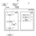
- Fig. 3 is a block diagram showing an example of the configuration of the information processing device 1.
- the information processing device 1 includes a control unit 2 that performs overall control of each unit of the information processing device 1, and a memory unit 3 that stores various data used by the control unit 2.
- the control unit 2 includes an acquisition unit 21, a first estimation unit 23, an output unit 24, and a learning unit 25.
- the memory unit 3 stores a control program 31, which is a program for performing various controls of the information processing device 1, as well as first teacher data 32 and a learned first learning model 33.
- the acquisition unit 21 acquires input information including a first image in which at least a part of a target bone is captured.
- the acquisition unit 21 shown in FIG. 3 may be capable of acquiring the first image from the image management device 5.
- the input information is input data input to the first estimation unit 23.
- the acquisition unit 21 may acquire attribute information and surgery information of the subject from the electronic medical record management device 6 in the medical facility 8.
- the first estimation unit 23 estimates the above-mentioned first estimation information by inputting input information to the trained first learning model 33.
- the trained first learning model 33 has been trained in advance using the first teacher data 32.
- the first teacher data may be data including a second image showing a human bone and bone information related to at least one of the bone density, bone mass, and bone quality of the bone.
- the first teacher data may be data including at least a second image showing a bone in which an implant is not embedded, and bone information related to at least one of the bone density, bone mass, and bone quality of the bone, for each of a plurality of patients.
- the first teacher data may be data including a second image showing a bone in which an implant is embedded, and bone information related to at least one of the bone density, bone mass, and bone quality of the bone, for each of a plurality of patients.
- the first estimation unit 23 may estimate first estimated information including bone information regarding at least one of bone density, bone mass, and bone quality of each of a plurality of regions of the target bone, including a region adjacent to the implant.
- the multiple regions can be set to any region adjacent to the implant.
- the multiple regions adjacent to the implant may be a region that appears in one image.
- the multiple regions adjacent to the implant may refer to a region that contacts the implant.
- the multiple regions adjacent to the implant may refer to a region that does not contact the implant.
- the multiple regions will be described using the stem of a cementless artificial hip joint as an example, but are not limited to this.
- Each of the multiple regions may be arranged along a first direction L1 from the insertion port side (proximal side) where the stem of the implant is inserted to the tip side (distal side) of the stem.
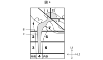
- regions divided by Gruen classification can be used, as shown in FIG. 4.
- FIG. 4 is a diagram showing an example of multiple regions in a target bone (right femur) B1.
- FIG. 4 is a diagram showing an artificial hip joint (i.e., implant I1) embedded in a right hip joint as viewed from the ventral side (front). That is, in FIG. 4, the left side is the outside (right arm side) and the right side is the inside (left arm side).
- FIG. 4 shows area 1 (outside) and area 7 (inside) located closest to the insertion opening, area 2 (outside) and area 6 (inside) next closest to the insertion opening, area 3 (outside) and area 5 (inside) next closest to the insertion opening, and area 4 furthest from the insertion opening.
- the implant embedded in the subject's bone is an artificial hip implant including a stem
- the target bone is the femur in which the stem is embedded.
- the first estimation unit 23 may estimate multiple pieces of first estimated information within a region of the femur, which is the target bone, classified by the Gruen classification.
- the multiple pieces of first estimated information may include first estimated information within a proximal region of the femur in which the stem is embedded.
- the first estimation unit 23 may estimate bone information related to at least one of bone density, bone mass, and bone quality for each of the multiple sites thus divided.
- the first estimation unit 23 may estimate different items for each of the multiple sites, or may estimate the same items.
- the first estimation unit 23 may estimate bone density, bone mass, and bone quality (e.g., cancellous bone structure index) for sites 1, 7, 2, and 6, while estimating only bone density for sites 3, 4, and 5.
- the first estimation unit 23 may estimate only bone density, for example, for all sites 1 to 7.
- the bone density may be a value related to the density of the bone.
- the bone density may be represented by at least one of bone mineral density per unit area (g/cm 2 ), bone mineral density per unit volume (g/cm 3 ), YAM (%), AGE, T-score, and Z-score.
- YAM (%) is an abbreviation for "Young Adult Mean” and may be called the young adult average percentage.
- the bone mineral density may be a value expressed as bone mineral density per unit area (g/ cm2 ) and YAM (%).
- AGE may be a value compared to the average value of the same age or age group.
- the bone mineral density may be an index determined by a guideline or may be an original index.
- the bone mineral density may be a value used in the osteoporosis guidelines (such as, but not limited to, the 2015 edition of the Prevention and Treatment Guidelines of the Japan Osteoporosis Society).
- the first estimation unit 23 may estimate the first estimated information for all the parts 1 to 7 as the first estimated information. Alternatively, the first estimation unit 23 may estimate only some parts as the first estimated information. More specifically, in order to estimate the loosening of the implant in the target bone, bone information including at least one of bone density, bone mass, and bone quality in the part of the target bone B1 on the insertion side where the stem of the implant I1 is inserted (i.e., parts 1, 2, 6, and 7 in FIG. 4) is more important. Therefore, the first estimation unit 23 may estimate, for example, only parts 1 and 7 as the first estimated information. Alternatively, the first estimation unit 23 may estimate, as the first estimated information, with different estimation accuracy for each part based on the importance of the part for the loosening of the implant I1.
- Estimating with different accuracy for each part includes, for example, changing the number of calculations for each part, changing the learning model for each part, and changing the variables during calculation for each part.
- areas 1 and 7 may be estimated with high accuracy, and other areas may be estimated with lower accuracy than areas 1 and 7.
- each of the multiple sites may be a site along the second direction L2 from the medullary cavity side to the outer shell side of the target bone B1 (i.e., a direction away from the axis of the stem of the embedded implant I1).
- bone information including at least one of bone density, bone volume, and bone quality in the site of the target bone B1 near the stem of the implant I1 on the medullary cavity side of the target bone B1 is more important.
- the multiple regions may be set two-dimensionally by dividing the regions in the first direction L1 and the second direction L2.
- the multiple regions may be set to regions with different areas.
- the multiple regions may also be set to regions with smaller areas of specific parts.
- the multiple regions may be set arbitrarily according to the attribute information of the subject. For example, if the subject has a history of fractures, the specific regions may be set to smaller areas than those of subjects without a history of fractures. More specifically, in the first direction L1, the areas of the regions may be set to be smaller than those of other regions as they move toward the regions 1 and 7. In the second direction L2, the areas of the regions may be set to be smaller as they move closer to the implant I1 than those of the regions farther from the implant.
- the multiple regions may be set to avoid the cement portion, for example, by considering the cement as part of the artificial joint.
- Example 1 In the case of a cementless artificial hip joint, the multiple sites can be set at any sites adjacent to the cup.
- the cup is embedded, for example, in the acetabulum of the pelvis.
- regions I to III according to the Chanley classification can be used, as shown in Figure 4.
- the implant embedded in the subject's bone is an artificial hip implant including a cup
- the target bone is the acetabulum in which the cup is embedded.
- the first estimation unit 23 may estimate multiple pieces of first estimated information within an area of the acetabulum, which is the target bone, classified by the Charnley classification.
- Example 2 The regions divided by the Gruen classification are not limited to the example shown in Figure 4, and can also be applied when the artificial hip joint is viewed from the side.
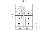
- Figure 5 is a diagram showing an example of multiple parts of the target bone (left femur) B2.
- Figure 5 is a diagram showing an artificial hip joint (i.e., implant I2) embedded in the left hip joint as viewed from the left arm side (side). That is, in Figure 5, the left side is the ventral side, and the right side is the dorsal side.
- Figure 5 shows part 8 (ventral side) and part 14 (dorsal side) located closest to the insertion opening, part 9 (ventral side) and part 13 (dorsal side) next closest to the insertion opening, part 10 (ventral side) and part 12 (dorsal side) next closest to the insertion opening, and part 11 which is furthest from the insertion opening.
- Example 3 A number of locations that can be set in the case of an artificial knee joint are described with reference to Figures 10 to 12.
- Figure 10 is a diagram showing an example of a number of locations in a target bone (left femur) B3.
- Figure 10 is a diagram showing an artificial knee joint (i.e., implant I3) embedded in the left femur B3 as viewed from the left arm side (side). That is, in Figure 10, the left side is the ventral side and the right side is the dorsal side.
- locations 1 to 7 are shown.
- Figure 11 is a diagram showing an example of a number of locations in a target bone (left tibia) B4.
- Figure 11 is a diagram showing an artificial knee joint (i.e., implant I4) embedded in the left tibia B4 as viewed from the ventral side (front). That is, in Figure 11, the left side is the inner side (right arm side) and the right side is the outer side (left arm side). In Figure 11, locations 1 to 7 are shown.
- Figure 12 is a diagram showing an example of a number of locations in a target bone (left tibia) B5.
- Figure 12 is a view of the artificial knee joint implanted in the left tibia B5, viewed from the left arm side (front). That is, in Figure 12, the left side is the ventral side, and the right side is the dorsal side.
- parts 1 to 3 are shown.
- each of the multiple sites may be arranged along a first direction L1 from the insertion port side (proximal side) where the stem of implant I2 to I5 is inserted to the tip side (distal side) of the stem.
- Each of the multiple sites may be arranged along a second direction L2 from the medullary cavity side to the outer shell side of the target bone (i.e., the direction away from the axis of the stem of implant I2 to I5 that is embedded).
- the first estimation unit 23 performs calculations based on the trained first learning model, and outputs a surgical treatment method suitable for the affected bone of the subject and an implant that can be used in the surgical treatment method from the output layer 232 (see FIG. 6 ).
- the first estimation unit 23 may be configured to extract features from the input information and use them as input data.
- the following known algorithms may be applied to extract the features.
- ⁇ Convolutional neural network (CNN) ⁇ Autoencoder ⁇ Recurrent neural network (RNN) ⁇ LSTM (Long Short-Term Memory) ⁇ ConvLSTM (Convolutional Long Short-Term Memory).
- the trained first learning model 33 is a calculation model used by the first estimation unit 23 when performing calculations based on input data.
- the trained first learning model 33 is generated by the learning unit 25 executing machine learning using the first teacher data 32 described later on an untrained neural network.
- the trained first learning model 33 can also be applied to non-human animals.
- the "patient" in the first teacher data 32 may be the same biological species as the "subject".
- the information processing device 1 according to the present disclosure is also capable of estimating first estimated information regarding at least any of bone information of bone density, bone mass, and bone quality of a bone in which an implant is embedded of a non-human animal. Specific examples of the first teacher data 32, the configuration of the neural network, and the learning process will be described later.
- the output unit 24 transmits the first estimated information estimated by the first estimation unit 23 to the terminal device 7.
- the information processing device 1 may be configured to include a display unit (not shown).
- the output unit 24 causes the display unit to display the above-mentioned information.
- the display unit may, for example, change the color of each divided portion according to the received first estimated information.
- the display unit may, for example, display the received first estimated information in the form of a heat map.
- the learning unit 25 controls a learning process for an untrained neural network.
- the learning unit 25 executes the learning process for the untrained neural network to create a trained neural network (trained first learning model 33) that functions as the first estimation unit 23.
- first teacher data 32 (described later) is used.
- a specific example of the learning performed by the learning unit 25 will be described later.
- the configuration of the first estimator 23 will be described below with reference to Fig. 6.
- the configuration shown in Fig. 6 is an example, and the configuration of the first estimator 23 is not limited thereto.
- the first estimation unit 23 performs calculations based on the trained first learning model 33 on the input data input to the input layer 231, and outputs output data from the output layer 232.
- the output data is bone information related to at least one of the bone density, bone volume, and bone quality of the bone in which the implant is embedded.
- the first estimation unit 23 in FIG. 6 includes a neural network having an input layer 231 and an output layer 232.
- FIG. 6 shows a case where the neural network is an LSTM, but is not limited to this.
- the neural network may be a ConvLSTM network that combines CNN and LSTM.
- the input layer 231 can extract features related to changes in the input data.
- the output layer 232 can calculate new features based on the features extracted by the input layer 231, the time change of the input data, and the initial value.
- the time change is the difference in time between the time when the input data is acquired and the time to be estimated, and may be input by the user of the system as 1 year, 3 years, 5 years, 10 years, 20 years, or 50 years, or a difference automatically determined within the system may be input.
- the initial value may be the value of bone mass or bone quality at the time when the input data is acquired.
- the initial value may be estimated by the first estimation unit 23, or a value of bone mass or bone quality measured by another device may be used.
- the input layer 231 and the output layer 232 each have multiple LSTM layers. Each of the input layer 231 and the output layer 232 may have three or more LSTM layers.
- Fig. 7 is a flowchart showing an example of the flow of the learning process by the learning unit 25.
- the learning unit 25 acquires the first teacher data 32 from the memory unit 3 (step S1).
- the first teacher data 32 includes explanatory variables and objective variables to be input to the input layer 231.
- the explanatory variables are the second image showing a human bone
- the objective variables may be bone information related to at least one of the bone density, bone mass, and bone quality of the human bone shown in the second image.
- the objective variables may include at least one of the area and position information of the bone information, or may include information on the loosening of the implant.
- the area or position information of the bone information may be used as the explanatory variable.
- the position information may be information that represents a position on the image, and may be XY coordinates on the image.
- the position information may be information indicating the interface between the bone and the implant, or a position a predetermined distance away from the interface of the implant.
- the position information may be the name of a specific part of the human body.
- the position information may be, for example, the trochanter part for the proximal part of the femur, the posterior condyle part for the distal part of the femur, or the medial side for the proximal part of the tibia.
- the information regarding implant loosening may be at least one of the following: the occurrence or absence of loosening, the probability of loosening, the presence or absence of a bone radiography image, the thickness of the bone radiography image, the range of the bone radiography image, changes in the thickness or range of the bone radiography image, sensation or pain felt by the patient, and changes in sensation or pain felt by the patient.
- the learning unit 25 inputs a second image showing a person's bones to the input layer 231 (step S2).
- the learning unit 25 acquires bone information (i.e., output data) relating to at least one of the bone density, bone mass, and bone quality of the bones of the person appearing in the second image input in step S2 from the output layer 232 (step S3).
- This output data contains the same content as the objective variable of the first teacher data 32.
- steps S2 and S3 may be reversed.
- steps S2 and S3 may be configured to be executed simultaneously.
- the learning unit 25 acquires a target variable related to the person appearing in the second image input in step S2, which is included in the first teacher data 32.
- the learning unit 25 compares the output data acquired in step S3 with the target variable related to the person, calculates an error (step S4), and adjusts the first learning model 33 being learned so as to reduce the error (step S5).
- the backpropagation method may be adopted as a method for adjusting the first learning model.
- the first learning model after adjustment becomes the new first learning model, and in subsequent calculations, the first estimation unit 23 uses the new first learning model.
- parameters used by the first estimation unit 23 e.g., filter coefficients, weighting coefficients, etc. can be adjusted.
- step S6 If the error is not within the predetermined range and explanatory variables for all people included in the first teacher data 32 have not been input (NO in step S6), the learning unit 25 returns to step S2 and repeats the learning process. If the error is within the predetermined range and explanatory variables for all people included in the first teacher data 32 have been input (YES in step S6), the learning unit 25 ends the learning process.
- the first estimation unit 23 can estimate first estimated information regarding at least any of bone information of bone density, bone mass, and bone quality of a portion of the target bone from input information including a first image showing at least a portion of the target bone in which an implant is embedded.
- Fig. 13 is a flowchart showing another example of the flow of the learning process by the learning unit 25.
- the learning unit 25 acquires the first teacher data 32 from the memory unit 3 (step S1a).
- the first teacher data 32 includes explanatory variables and objective variables to be input to the input layer 231.
- the explanatory variables include a second image showing at least the bone in which the implant is embedded for each of the multiple patients, and the objective variable is bone information related to at least one of the bone density, bone volume, and bone quality of the bone in which the implant is embedded.
- the learning unit 25 inputs a second image showing at least a portion of a bone in which an implant is embedded of a certain patient (referred to as Patient A) to the input layer 231 (step S2a).
- the learning unit 25 obtains output data relating to at least any of bone information, such as bone density, bone mass, and bone quality, of the bone in which the implant of patient A is embedded from the output layer 232 (step S3a).
- This output data contains the same content as the objective variable of the first teacher data 32.
- steps S2a and S3a may be reversed.
- steps S2a and S3a may be executed simultaneously.
- the learning unit 25 acquires the objective variables for patient A contained in the first teacher data 32.
- the learning unit 25 compares the output data acquired in step S3a with the objective variables for patient A, calculates the error (step S4a), and adjusts the first learning model 33 being learned so as to reduce the error (step S5a).
- the backpropagation method may be adopted as a method for adjusting the first learning model.
- the first learning model after adjustment becomes the new first learning model, and in subsequent calculations, the first estimation unit 23 uses the new first learning model.
- parameters used by the first estimation unit 23 e.g., filter coefficients, weighting coefficients, etc. can be adjusted.
- step S6a If the error is not within the predetermined range and explanatory variables for all patients included in the first teacher data 32 have not been input (NO in step S6a), the learning unit 25 returns to step S2a and repeats the learning process. If the error is within the predetermined range and explanatory variables for all patients included in the first teacher data 32 have been input (YES in step S6a), the learning unit 25 ends the learning process.
- the first estimation unit 23 can estimate first estimated information regarding at least any of bone information of bone density, bone mass, and bone quality of a portion of the target bone from input information including a first image showing at least a portion of the target bone in which an implant is embedded.
- the first teacher data 32 may further include at least one of attribute information of each of the multiple patients and surgical information on the implantation technique for embedding the implant in the bone of each patient.
- the trained first learning model 33 can more accurately estimate the first estimated information on at least one of bone information of the target bone, such as bone density, bone mass, and bone quality, from the input information.
- the input information may include at least a first image showing the target bone, attribute information of the subject, and surgical information on the implantation technique for embedding the implant in the target bone.
- the attribute information may include at least one of the following for each patient (and subject): age, sex, height, weight, race, whether or not the patient has undergone menopause, whether or not the patient has undergone a fracture, the number of fractures, the location of the fracture, history of fractures, information on lifestyle habits, information on medications taken (medication information), information indicating the results of a blood test (blood test information), urine test information, saliva test information, medical history, medical history of the subject's family, genetic information, birth information, and menopause information, predicted menopause prediction based on hormone information, and birth information.
- the surgical information may include at least one of the following: the type of implant embedded in the bone (and the subject bone) of each patient, the size of the implant, the surgical procedure applied, the surgical time of the implant, the amount of blood loss during the implant, information indicating the medical facility that performed the implant, and information indicating the surgeon who performed the implant.
- the lifestyle habits may be, for example, sleep time, wake-up time, sleep duration, daily exercise amount, meal contents, meal time, meal duration, blood glucose level, etc.
- the meal contents may include, for example, at least one of the name of the dish, the ingested ingredients, and the intake amount.
- the meal contents may be, for example, an estimated intake amount including at least one of calcium, vitamin B, vitamin D, and vitamin K.
- the blood glucose level may be, for example, a designated value estimated from parameters acquired by a wearable device.
- the information processing device 1 may acquire attribute information of the subject from the attribute information management device 4. When the acquired first image and/or second image has this attribute information added thereto, the information processing device 1 may extract the attribute information from the first image and/or the second image.
- Medication information may include, for example, the name of the medication, the amount taken, and the duration of taking the medication.
- Information regarding medications taken may include information regarding the steroid drug being used.
- Blood test information may be, for example, information regarding the results of at least one of a biochemistry test, a glucose metabolism test, and an endocrine system test.
- the patient's (and subject's) attribute information and surgical information may both be information related to the prognosis of the affected area to which the implant placement surgery has been applied, or information that may affect the prognosis of the affected area.
- the information processing device 1 can provide the first estimated information to a doctor or the like with greater accuracy. This allows the information processing device 1 to assist in estimating the risks that may arise in the prognosis of the target bone.
- the adjustment of the trained first learning model 33 may be performed in a computer different from the information processing device 1.
- the information processing device 1 may install and use the trained first learning model 33. That is, in the information processing device 1, the learning unit 25 is not a required component.
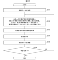
- Fig. 8 is a flowchart showing an example of the flow of processing performed by the information processing device 1.
- Fig. 8 shows an example of processing performed when the information processing device 1 outputs first estimated information on bone information of a target bone from input information.
- the acquisition unit 21 acquires input information including a first image that shows at least a portion of the target bone (step S11: acquisition step).
- the first estimation unit 23 estimates first estimated information regarding at least one of the bone information of the target bone, namely, bone density, bone mass, and bone quality, by inputting the input information into the trained first learning model 33 (step S12: estimation step).
- the output unit 24 outputs the first estimated information estimated in step S12 (step S13: output step).
- the information processing device 1 and the information processing system 100a can output useful information for doctors and others to estimate the risks that may occur in the affected area of a subject who has undergone implant placement surgery.
- the information processing system 100a may be configured to output second estimated information about events that may occur in the subject due to the placement of the implant, the second estimated information being based on the input information.
- Fig. 9 is a block diagram showing an example of the configuration of the information processing device 1a.
- the information processing device 1a can be applied to the information processing systems 100a and 100b.
- the information processing device 1a includes a control unit 2a that performs overall control of each unit of the information processing device 1a, and a memory unit 3a that stores various data used by the control unit 2a.
- the control unit 2a includes an acquisition unit 21, a first estimation unit 23, an output unit 24, and a learning unit 25, as well as a second estimation unit 26.
- the memory unit 3a stores a control program 31, which is a program for performing various controls of the information processing device 1a, first teacher data 32, a learned first learning model 33, and a learned second learning model 34.
- the second estimation unit 26 estimates the second estimated information from the first image included in the input information using the second learning model 34 trained using the second teacher data.
- the second teacher data is data including a third image showing a human bone and progress information regarding an event caused by embedding an implant (third implant) in the bone.
- the second teacher data may be, for example, data including a third image showing at least a portion of the bone in which the implant is embedded for each of a plurality of patients and progress information regarding an event caused by embedding the implant.
- the output unit 24 transmits the estimated second estimated information to the terminal device 7.
- the third image included in the second teacher data may be, for example, an image taken within a certain period of time (e.g., six months) after the progress information after implant placement is obtained.
- the second teacher data may further include a combination of the following information (i) and (ii).
- the future bone density may be information regarding the bone condition or bone density when a predetermined period of time has passed since the third image taken in the past (e.g., the actual bone density measured when a predetermined period of time has passed since the third image taken in the past).
- the current bone density may be an actual measurement of the bone density measured when the third image is captured.
- the current bone density may be a bone density estimated from the analysis of the image of the bone shown in the third image.
- the events occurring due to the embedding of the implant may include at least any of the following. - Loosening of the implant. - Fracture of the bone in which the implant is placed. Dislocation of the joint in relation to the bone in which the implant is placed. - Infection of the affected area, including the bone in which the implant is placed. - Implant fracture.
- the loosening of the implant may be detected based on at least one of an X-ray image of the implant and the bone interface in which the implant is embedded, a bone radiograph, and a medical examination (e.g., interview and/or palpation, etc.).
- the loosening of the implant may be determined based on at least one of the following: sensation felt by the patient, pain, the gap between the implant and the bone (e.g., the width of the gap), and the change in position of the implant from when it was embedded; the presence or absence of loosening and the degree of loosening.
- Fractures of the bone in which the implant is embedded, dislocations of the joints related to the bone in which the implant is embedded, infections of the affected area including the bone in which the implant is embedded, and fractures of the implant may be detected based on at least one of an X-ray image of the affected area and a medical examination (e.g., interview and/or palpation, etc.). Fractures of the bone in which the implant is embedded include, for example, fractures of bones in the skeleton surrounding the bone in which the implant is embedded.
- the second teacher data may be, for example, progress information at one time point, or may include progress information at multiple different time points.
- the tendency between the multiple different time points can be used as teacher data.
- the trained second learning model 34 may be a learning model trained using second teacher data including, as explanatory variables, the third image and progress information of the patient acquired at multiple different time points, and including, as objective variables, events that occurred due to the implantation of the patient's implant confirmed at the multiple different time points.
- the progress information may include, for example, information regarding at least one of the position of the bone radiography, the thickness of the bone radiography, the range of the bone radiography, sensation by the patient, pain (e.g., pain intensity, type of pain, duration of pain, etc.), the distance or angle between the implant and the bone, and the change in position between the time of implantation and the current time.
- the doctor or other medical professional can accurately determine the risk that may occur in the affected area of the subject. This allows the information processing device 1a to assist the doctor or other medical professional in estimating the risk that may occur in the prognosis of the affected area of the subject.
- implant loosening when implant loosening is predicted in this manner, the extent to which it will improve with treatment may also be indicated. It may also be possible to predict how implant loosening will change as a result of administering treatment to the patient.
- Implant loosening occurs due to a decrease in bone density of the bone surrounding the implant. In other words, improving the bone density of the bone surrounding the implant leads to improving the loosening of the implant.
- the doctor or the like can refer to the first estimated information and the second estimated information to determine a treatment plan that includes prescribing to the subject a drug that is expected to have the effect of suppressing the occurrence of loosening of the implant and delaying the occurrence of loosening of the implant.
- the drug considered for prescription to the subject may include, for example, a drug that has an effect on bone formation and a drug that has an effect on bone resorption.
- Drugs that have an effect on bone formation include, but are not limited to, active vitamin D3 preparations (e.g., calcitriol, eldecalcitol, or alphacalcidol), teriparatide acetate, and teriparatide (recombinant).
- Drugs that have an effect on bone resorption include, but are not limited to, calcitonin preparations, bisphosphonate preparations, and anti-RANKL monoclonal antibodies.
- Fig. 2 is a diagram showing an example configuration of an information processing system 100b according to another aspect of the present disclosure.
- the LAN in medical facility 8a may be communicatively connected to one or more terminal devices 7a, as well as an image management device 5a and an electronic medical record management device 6a.
- the LAN in medical facility 8b may be communicatively connected to one or more terminal devices 7b, as well as an image management device 5b and an electronic medical record management device 6b.
- medical facility 8 when there is no particular distinction between medical facilities 8a and 8b, they will be referred to as "medical facility 8."
- terminal devices 7a and 7b, image management devices 5a and 5b, and electronic medical record management devices 6a and 6b When there is no particular distinction between terminal devices 7a and 7b, image management devices 5a and 5b, and electronic medical record management devices 6a and 6b, they will be referred to as "terminal devices 7,” “image management devices 5,” and “electronic medical record management devices 6,” respectively.
- FIG. 2 an example is shown in which the LANs of medical facility 8a and medical facility 8b are connected to a communication network 9.
- the information processing device 1 is not limited to the configuration shown in FIG. 2 as long as it is communicably connected to the image management device 5 and electronic medical record management device 6 in each medical facility via the communication network 9.
- the information processing device 1 may be installed in medical facility 8a or medical facility 8b.
- the information processing device 1 can acquire a first image of the subject Pa who has been examined at the medical facility 8a from the image management device 5a of the medical facility 8a.
- the information processing device 1 can also acquire attribute information and surgery information of the subject Pa from the electronic medical record management device 6a of the medical facility 8a.
- the information processing device 1 then transmits the first estimated information about the subject Pa to the terminal device 7a installed in the medical facility 8a.
- the information processing device 1 can acquire attribute information and surgery information of the subject Pb from the electronic medical record management device 6b of the medical facility 8b.
- the information processing device 1 then transmits the first estimated information about the subject Pb to the terminal device 7a installed in the medical facility 8b.
- the terminal device 7 may have the function of the acquisition unit 21, and the information processing device 1 may receive input information from the terminal device 7.
- the information processing device 1 may receive input information from the terminal device 7.
- the function of the learning unit 25 may be configured to install a trained first learning model 33, which has been trained by a computer other than the information processing device 1, in the information processing device 1.
- the function of the second estimation unit 26 may be provided by another computer or terminal device 7 different from the information processing device 1. Also, in the information processing systems 100a and 100b, the function of the second estimation unit 26 may be provided by another computer or terminal device 7 different from the information processing device 1.
- a third estimated information of bone information related to the bone condition of the subject estimated using the third learning model 1034 is output.
- the learning model in this embodiment is trained using teacher data including at least one of information including a second medical image showing the trabecular bone of a specific person and trabecular bone information related to the trabecular bone condition of a specific person, and a second virtual image expressing the color shading in the second medical image for each predetermined area.
- the information processing system 1100a includes an information processing device 1001 instead of the information processing device 1 in the information processing system 100a in embodiment 1.
- the information processing device 1001 estimates bone information related to the bone condition of the subject from medical information including at least one of a first image showing the subject's bone trabeculae and a first virtual image expressing the color shading in the first image for each predetermined area.
- the information processing device 1001 may estimate the subject's future bone information or may estimate the subject's current bone information.
- the information processing device 1001 is a computer that transmits third estimated information of the subject's bone information to the terminal device 7.
- the information processing system 1100a includes an image management device 5A instead of the image management device 5 in embodiment 1.
- the information processing system 1100a may include a test numerical value management device 1005 and a diagnosis result management device 1006 in addition to the configuration of the information processing system 100a in embodiment 1.
- the information processing device 1001, the terminal device 7, the image management device 5A, the electronic medical record management device 6, the test numerical value management device 1005, and the diagnosis result management device 1006 may be communicatively connected by a LAN in the medical facility 8.
- the image management device 5A generates a virtual image that expresses the color shading in the first image for each specified area.
- the virtual image is generated from the shading of the cancellous bone and/or cortical bone parts and the non-bone parts of the bone image information that includes bone parts in the first image. More specifically, the virtual image can be generated, for example, by converting the bone shading from the bone image information into a numerical value for each specified area and generating an image in which the numerical value is expressed as a color shading.
- the predetermined area may be, for example, one pixel of an image as one unit, or multiple pixels of an image as one unit.
- at least one of the following may be considered: bone trabeculae, number of bone trabeculae (e.g., number of bone trabeculae per unit length), trabecular gap (e.g., spatial distance between bone trabeculae), trabecular width (width or thickness of bone trabeculae), trabecular orientation (e.g., degree of alignment of bone trabecular direction within a trabecula), and bone connectivity density (e.g., number of paths connecting the ends of bone trabeculae per unit area).
- the numerical value may be, for example, at least one of bone mass (e.g., numerical value in g), bone density, and cancellous bone structure index.
- the color shade may be, for example, two shades of white and black, grayscale (e.g., two shades of white and black plus a color that expresses a shade of gray that is an intermediate color between white and black in 254 shades), or a heat map using multiple colors.
- the color shading is not limited to these, and for example, one shading may be made by displaying the white color of the two gradations as transparent, or a predetermined value or more may be the subject of shading.
- the information processing device 1 may acquire a medical image showing the subject's bone trabeculae from the image management device 5A, and a virtual image generated using the medical image.
- the test value management device 1005 is a computer that functions as a server for managing test values obtained from tests performed at the medical facility 8.
- the test values include, for example, at least one of the following: KL (Kellgren-Lawrence) classification, bone morphology angle, muscle mass, MMSE (Mini Mental State Examination), blood test values (for example, at least one of bone formation marker, bone resorption marker, and vitamin K value), liver function marker, uric acid value, bone evaluation information, and malignant tumor marker.
- the information processing device 1001 may obtain the test values of the subject from the test value management device 1005.
- the diagnostic result management device 1006 is a computer that functions as a server for managing diagnostic results obtained by diagnoses performed at the medical facility 8.
- the information processing device 1001 may obtain the diagnostic results of the subject from the diagnostic result management device 1006.
- the diagnostic results may include the presence or absence of a fracture and the progression of osteoporosis.
- information regarding the cause such as a fragility fracture, a fatigue fracture, or a traumatic fracture, may be added.
- FIG. 14 shows an example of a configuration including an image management device 5A, an electronic medical record management device 6, a test value management device 1005, and a diagnosis result management device 1006, but is not limited to this.
- the configuration may include a management device that has the functions of any two or more of these devices, or all of them.
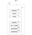
- Fig. 15 is a block diagram showing an example of the configuration of the information processing device 1001.
- the information processing device 1001 includes a control unit 1002 that performs overall control of each unit of the information processing device 1001, and a memory unit 1010 that stores various data used by the control unit 1002.
- the control unit 1002 includes an acquisition unit 1021, an estimation unit 1023, an output unit 1024, and a learning unit 1025.
- the memory unit 1010 stores a control program 1031, which is a program for performing various controls of the information processing device 1001, as well as teacher data 1032 and a trained third learning model 1034.
- the acquisition unit 1021 acquires input information including a first image of the subject.
- the input information is data input to the estimation unit 1023.
- the input information includes at least one of a first image showing the subject's trabecular bone and a virtual image expressing the color shading in the first image for each predetermined area.
- the first image showing the subject's trabecular bone may be referred to as a first medical image
- the virtual image expressing the color shading in the medical image for each predetermined area may be referred to as a first virtual image.
- the acquisition unit 1021 may acquire the first medical image and/or the first virtual image from the image management device 5A.
- the acquisition unit 1021 may acquire the first virtual image generated by a virtual image generation device other than the image management device 5A using the first medical image from the virtual image generation device. In addition to the first medical image and the first virtual image, the acquisition unit 1021 may acquire, as input information, attribute information of the subject from the electronic medical record management device 6, may acquire test values of the subject from the test value management device 1005, or may acquire diagnostic results of the subject from the diagnostic result management device 1006.
- the estimation unit 1023 estimates third estimated information, which is bone information related to the bone condition of the subject, by inputting the input information acquired by the acquisition unit 1021 to the third learning model 1034.
- third learning model 1034 is learned in advance using the teacher data 1032.
- the teacher data 1032 is data including medical information of a specific person.
- the specific person may be a patient suffering from a bone-related disease, or may be a person not suffering from a disease.
- the medical information included in the teacher data 1032 includes at least one of information including a second medical image showing the bone trabeculae of the specific person and trabecular information related to the state of the bone trabeculae of the specific person, and a second virtual image expressing the color shading in the second medical image for each specific area.
- the medical image showing the bone trabeculae of a specific person may be referred to as the second medical image
- the virtual image that represents the color shades in the second medical image for a specific area may be referred to as the second virtual image.
- the estimation unit 1023 may estimate the subject's future bone information by inputting input information including at least one of the first medical image and the first virtual image to the third learning model 1034.
- the estimation unit 1023 may estimate the subject's future bone information by (1) inputting the medical information including the first medical image to the third learning model 1034 trained using training data including at least information including a second medical image showing the bone trabeculae of a specific person and trabecular bone information related to the state of the bone trabeculae of the specific person, or (2) inputting medical information including the first virtual image to the third learning model 1034 trained using training data including at least a second virtual image that expresses the color shading in the second medical image for each specific area.
- the estimation unit 1023 may estimate, as the bone information, at least one of the following: cancellous bone structure index, fracture occurrence probability, osteoporosis possibility, drug efficacy, incident occurrence, bone density, trabecular number, trabecular space, and bone connectivity density, by inputting the above input information into the third learning model 1034.
- the bone information may be obtained by analyzing bone strength from the state of the cortical bone and/or cancellous bone.
- the third learning model 1034 is a calculation model used by the estimation unit 1023 when performing calculations based on input data.
- the learning unit 1025 executes machine learning using the teacher data 1032 described below on an untrained neural network, thereby generating the third learning model 1034.
- the third learning model 1034 can also be applied to non-human animals.
- the "prescribed person" in the teacher data 1032 only needs to be of the same biological species as the "subject.”
- the information processing device 1001 according to the present disclosure is also capable of estimating bone information relating to the condition of the bones of non-human animals.
- the teacher data 1032, the configuration of the neural network, and specific examples of the learning process will be described later.
- the output unit 1024 transmits the information estimated by the estimation unit 1023 to the terminal device 1030.
- the information processing device 1001 may be configured to include a display unit (not shown). In that case, the output unit 1024 causes the display unit to display the information estimated by the estimation unit 1023.
- the learning unit 1025 controls the learning process for the untrained neural network.
- the learning unit 1025 executes the learning process for the untrained neural network to create a trained neural network that functions as the estimation unit 1023.
- Teacher data 1032 (described later) is used for this learning. A specific example of the learning performed by the learning unit 1025 will be described later.
- the estimation unit 1023 performs calculations based on the third learning model 1034 on the input data input to the input layer 1210, and outputs output data from the output layer 1230.
- the output data is future bone information of the subject.
- the future bone information may be, for example, at least one of the following: cancellous bone structure index, probability of fracture occurrence, possibility of osteoporosis, drug efficacy, incident occurrence, bone density, trabecular number, trabecular gap, trabecular width, trabecular orientation, and bone connectivity density.
- the estimation unit 1023 in FIG. 16 includes a neural network 200 having an input layer 1210 and an output layer 1230.
- FIG. 16 shows a case where the neural network 1200 is a CNN.
- the neural network 1200 includes, for example, an input layer 1210, a hidden layer 1220, and an output layer 1230.
- the hidden layer 1220 is also called an intermediate layer.
- the hidden layer 1220 includes, for example, a plurality of convolutional layers 1240, a plurality of pooling layers 1250, and a fully connected layer 1260.
- the fully connected layer 1260 exists before the output layer 1230.
- the convolutional layer 1240 and the pooling layer 1250 are alternately arranged between the input layer 1210 and the fully connected layer 1260.
- the configuration of the neural network 1200 is not limited to the example in FIG. 16.
- the neural network 1200 may include one convolutional layer 1240 and one pooling layer 1250 between the input layer 1210 and the fully connected layer 1260.
- the neural network 1200 may be a neural network other than a convolutional neural network.
- Neural network 1200 is not limited to CNN, and may be LSTM.
- Neural network 1200 may be, for example, a ConvLSTM network that combines CNN and LSTM.
- the input layer can extract features related to changes in the input data.
- the output layer can calculate new features based on the features extracted in the input layer, the time changes in the input data, and the initial values.
- the input layer and output layer have multiple LSTM layers. Each of the input layer and output layer may have three or more LSTM layers.
- Fig. 17 is a flowchart showing an example of the flow of the learning process by the learning unit 1025.
- the learning unit 1025 acquires the teacher data 1032 from the storage unit 1010 (step S101).
- the teacher data 1032 includes information including the second medical image showing the trabecular bone of a specific person and trabecular bone information related to the state of the trabecular bone of the specific person, at least one of the second virtual images, and data related to the state of the trabecular bone of the specific person a specific time after the second medical image is captured, and includes explanatory variables and objective variables to be input to the input layer 1210.
- the explanatory variables are the information including the second medical image showing the trabecular bone of a specific person and trabecular bone information related to the state of the trabecular bone of the specific person, and at least one of the second virtual images, and the objective variable is data related to the state of the trabecular bone of the specific person a specific time after the second medical image is captured.
- the learning unit 1025 inputs information including a second medical image showing the trabeculae of a certain person (referred to as person A) and trabecular bone information related to the state of the trabeculae of the specified person, and information including at least one of the second virtual images to the input layer 210 (step S102).
- person A a second medical image showing the trabeculae of a certain person
- trabecular bone information related to the state of the trabeculae of the specified person
- the learning unit 1025 obtains output data related to bone information of person A from the output layer 1230 (step S103).
- This output data contains the same content as the objective variable of the teacher data 1032.
- steps S102 and S103 may be reversed.
- steps S102 and S103 may be executed simultaneously.
- the learning unit 1025 acquires the objective variables for person A contained in the teacher data 1032.
- the learning unit 1025 compares the output data acquired in step S103 with the objective variables for person A to calculate the error (step S104), and adjusts the third learning model 1034 being learned so as to reduce the error (step S105).
- the backpropagation method may be adopted as a method for adjusting the learning model.
- the adjusted learning model becomes the new learning model, and in subsequent calculations, the estimation unit 1023 uses the new learning model.
- parameters used by the estimation unit 1023 e.g., filter coefficients, weighting coefficients, etc. can be adjusted.
- step S106 If the error is not within the predetermined range and explanatory variables for all people included in the teacher data 1032 have not been input (NO in step S106), the learning unit 1025 returns to step S102 and repeats the learning process. If the error is within the predetermined range and explanatory variables for all people included in the teacher data 1032 have been input (YES in step S106), the learning unit 1025 ends the learning process.
- the estimation unit 1023 can estimate the subject's future bone information from medical information including at least one of a first medical image showing the subject's bone trabeculae and a first virtual image that expresses the color shading in the first medical image for each specified area.
- the teacher data 1032 includes multiple first medical images and/or first virtual images of the same person
- the third learning model 1034 may be constructed based on the change over time in the feature amount of a characteristic area. This allows the subject's future bone information to be estimated taking into account the change over time in the state of the bone trabeculae, thereby improving the accuracy of the estimation.
- Fig. 18 is a flowchart showing an example of the flow of processing performed by the information processing device 1001.
- the acquisition unit 1021 acquires medical information including at least one of a first medical image showing the subject's bone trabeculae and a first virtual image that represents the color shading in the first medical image for each specified area (step S1011: acquisition step).
- the estimation unit 1023 estimates the subject's future bone information by inputting the acquired medical information into the third learning model 1034 (step S1012: estimation step).
- the output unit 1024 outputs each piece of information including the bone information estimated in step S1012 (step S1013: output step).
- the information processing device 1001 and the information processing system 1100a estimate the subject's future bone information from medical information including at least one of a first medical image showing the subject's bone trabeculae and a first virtual image that expresses the color shading in the first medical image for each specified area.
- the first medical image shows the bone trabeculae, which are the internal structure of the bone. Therefore, the estimation result output from the third learning model 1034 using the first medical image or the first virtual image generated using the first medical image as input information by the estimation unit reflects the internal structure of the bone, and therefore the estimation accuracy is high.
- the information processing device 1001 and the information processing system 1100a can estimate bone information related to the subject's future bone condition with high accuracy.
- the information processing device 1001 estimates bone information related to the subject's future bone condition, but the information processing device 1001 of this embodiment is not limited to this.
- the information processing device 1001 may estimate bone information related to the subject's current bone condition.
- the learning unit 1025 may generate the third learning model 1034 using data related to the state of the bone trabeculae of the specified person at the time the second medical image was captured as the objective variable. This allows the estimation unit 1023 to estimate bone information related to the subject's current bone condition by inputting medical information including at least one of the first medical image and the first virtual image into the third learning model 1034.
- the estimation unit 1023 may output at least one of a first estimation result assuming that the subject has reached menopause and a second estimation result assuming that the subject will not reach menopause. This makes it possible to output an estimation result with higher accuracy that takes into account the presence or absence of menopause.
- the estimation unit 1023 may simultaneously output the first estimation result assuming that the subject has reached menopause and the second estimation result assuming that the subject will not reach menopause.
- the information processing device 1001 may not be a computer installed in a specific medical facility 8, but may be communicably connected to a LAN provided in each of a plurality of medical facilities 8 via a communication network 1009.
- Fig. 19 is a diagram showing an example configuration of an information processing system 1100b according to another aspect of the present disclosure.
- the LAN in medical facility 8a may be communicatively connected to one or more terminal devices 7a, as well as an image management device 5Aa, an electronic medical record management device 6a, a test numerical value management device 1005a, and a diagnosis result management device 1006a.
- the LAN in medical facility 8b may be communicatively connected to one or more terminal devices 7b, as well as an image management device 5Ab, an electronic medical record management device 6b, a test numerical value management device 1005b, and a diagnosis result management device 1006b.
- medical facility 8 when there is no particular distinction between medical facilities 8a and 8b, they will be referred to as “medical facility 8." Additionally, when no distinction is made between terminal devices 7a and 7b, image management devices 5Aa and 5Ab, electronic medical record management devices 6a and 6b, test numerical value management devices 1005a and 1005b, and diagnostic result management devices 1006a and 1006b, they will be referred to as "terminal device 7," “image management device 5A,” “electronic medical record management device 6,” “test numerical value management device 1005,” and “diagnosis result management device 1006,” respectively.
- FIG. 19 an example is shown in which the LANs of medical facility 8a and medical facility 8b are connected to a communication network 1009.
- the information processing device 1001 is not limited to the configuration shown in FIG. 19 as long as it is communicably connected to the image management device 5A, electronic medical record management device 6, test value management device 1005, and diagnosis result management device 1006 in each medical facility via the communication network 1009.
- the information processing device 1001 may be installed in medical facility 8a or medical facility 8b.
- the information processing device 1001 can acquire a first image, attribute information, test values, and diagnosis results of subject Pa who has been examined at the medical facility 8a from the image management device 5Aa, electronic medical record management device 6a, test value management device 1005a, and diagnosis result management device 1006a of the medical facility 8a.
- the information processing device 1001 then transmits the estimation results of future bone information of subject Pa to terminal device 7a installed in the medical facility 8a.
- the information processing device 1001 transmits future bone information of subject Pb to terminal device 7b.
- the terminal device 7 may have the function of the acquisition unit 1021, and the information processing device 1001 may receive input information from the terminal device 7.
- the information processing device 1001 may also receive input information from the terminal device 7.
- a third learning model 1034 in which the function of the learning unit 1025 has been subjected to learning processing by a computer other than the information processing device 1001 may be installed in the information processing device 1001.
- the function of the learning unit 1025 may be provided by a computer or terminal device 1030 other than the information processing device 1001.
- the function of the estimation unit 1023 may be provided by a computer or terminal device 1030 other than the information processing device 1001.
- the functions of the information processing device 1, 1a, 1001 can be realized by a program for causing a computer to function as the device, and a program for causing a computer to function as each control block of the device (particularly each part included in the control unit 2, 2a, 1002).
- the device includes a computer having at least one control device (e.g., a processor) and at least one storage device (e.g., a memory) as hardware for executing the program.
- control device e.g., a processor
- storage device e.g., a memory
- the above program may be recorded on one or more computer-readable recording media, not on a temporary basis.
- the recording media may or may not be included in the device. In the latter case, the above program may be supplied to the device via any wired or wireless transmission medium.
- each of the above control blocks can be realized by a logic circuit.
- a logic circuit for example, an integrated circuit in which a logic circuit that functions as each of the above control blocks is formed is also included in the scope of the present invention.
- each process described in each of the above embodiments may be executed by AI (Artificial Intelligence).
- AI Artificial Intelligence
- the AI may run on the control device, or may run on another device (such as an edge computer or a cloud server).
- the information processing system comprises an acquisition unit that acquires input information including a first image showing at least a portion of a target bone in which a first implant of a subject is embedded, a first estimation unit that inputs the input information into a first learning model trained using first teacher data including a second image showing at least a portion of a bone of an animal including a human, and bone information regarding at least one of bone density, bone mass, and bone quality of the bone, thereby estimating first estimated information regarding at least one of bone density, bone mass, and bone quality of the target bone, and an output unit that outputs the first estimated information.
- the second image may include an image showing at least a portion of the bone in which the second implant is embedded.
- the first estimated information may include information on at least one of bone density, bone mass, and bone quality for a portion of the region of the target bone in which the first implant is embedded.
- the first estimated information may include information on at least one of bone density, bone mass, and bone quality of multiple sites in the target bone, including a site adjacent to the first implant.
- the information processing system may be any one of aspects 1 to 4 above, in which the first implant is an artificial hip joint implant including a stem, the target bone is a femur in which the stem is embedded, and the first estimation unit estimates a plurality of pieces of the first estimated information within an area of the femur classified by the Gruen classification.
- the first estimated information may include the first estimated information within the proximal region of the femur in which the stem is embedded.
- the information processing system may be any one of aspects 1 to 4 above, in which the first implant is an artificial hip implant including a cup, the target bone is an acetabulum in which the cup is embedded, and the first estimation unit may estimate a plurality of pieces of the first estimated information within an area of the acetabulum classified by the Charnley classification.
- the information processing system in any one of aspects 1 to 7 above, further includes a second estimation unit that inputs the input information into a second learning model trained using second teacher data including a third image showing at least a part of a bone of an animal, including a human, and progress information regarding an event that has occurred due to the embedding of a third implant in the bone, and estimates second estimated information regarding an event that may occur in the subject due to the embedding of the first implant, and the output unit may transmit the second estimated information.
- a second estimation unit that inputs the input information into a second learning model trained using second teacher data including a third image showing at least a part of a bone of an animal, including a human, and progress information regarding an event that has occurred due to the embedding of a third implant in the bone, and estimates second estimated information regarding an event that may occur in the subject due to the embedding of the first implant, and the output unit may transmit the second estimated information.
- the event may include at least one of the following: loosening of the first implant, fracture of the bone in which the first implant is embedded, dislocation of a joint associated with the bone in which the first implant is embedded, infection of an area including the bone in which the first implant is embedded, and fracture of the first implant.
- the input information may include at least one of attribute information of the subject and surgical information regarding the implantation procedure in which the first implant was embedded in the target bone.
- the attribute information may include at least any of the subject's age, sex, height, weight, race, whether or not they have experienced menopause, whether or not they have had a fracture, the number of fractures, the locations of fractures, their fracture history, information about their lifestyle habits, information about medications they are taking, and information showing the results of blood tests.
- the surgical information may include at least any of the following: the model of the first implant embedded in the target bone, the size of the first implant, the surgical procedure, the surgical time of the implantation procedure, the amount of blood loss during the implantation procedure, information indicating the medical facility that performed the implantation procedure, and information indicating the surgeon who performed the implantation procedure.
- the first implant may include at least one of an artificial joint, a spinal implant, a trauma implant, a plastic implant, and a dental implant.
- the artificial joint may be at least one of an artificial hip joint, an artificial knee joint, an artificial shoulder joint, an artificial elbow joint, an artificial ankle joint, and an artificial finger joint
- the spinal implant may be at least one of an instrumentation, a cage, an artificial intervertebral disc, and an artificial vertebral body
- the trauma implant may be at least one of a plate, a screw, and a nail
- the plastic implant may be at least one of a skull plate and a nasal bone prosthesis.
- the control method of the information processing system includes an acquisition step of acquiring input information including a first image showing at least a portion of a target bone in which a first implant of a subject is embedded, and an output step of inputting the input information into a learning model trained using a second image showing at least a portion of a bone of an animal, including a human, and first teacher data including bone information related to at least one of the bone density, bone mass, and bone quality of the bone, estimating first estimated information related to at least one of the bone density, bone mass, and bone quality of the target bone, and outputting the first estimated information.
- the control program of the information processing device is a control program for causing a computer to function as the information processing system described in any one of aspects 1 to 14 above, and is a control program for causing a computer to function as the acquisition unit, the first estimation unit, and the output unit.
- the recording medium according to aspect 17 of the present disclosure is a computer-readable recording medium having the control program described in aspect 16 recorded thereon.
Landscapes
- Health & Medical Sciences (AREA)
- Engineering & Computer Science (AREA)
- Medical Informatics (AREA)
- Public Health (AREA)
- Life Sciences & Earth Sciences (AREA)
- General Health & Medical Sciences (AREA)
- Biomedical Technology (AREA)
- Pathology (AREA)
- Radiology & Medical Imaging (AREA)
- Nuclear Medicine, Radiotherapy & Molecular Imaging (AREA)
- Epidemiology (AREA)
- Primary Health Care (AREA)
- Data Mining & Analysis (AREA)
- Animal Behavior & Ethology (AREA)
- Heart & Thoracic Surgery (AREA)
- Optics & Photonics (AREA)
- High Energy & Nuclear Physics (AREA)
- Biophysics (AREA)
- Veterinary Medicine (AREA)
- Molecular Biology (AREA)
- Surgery (AREA)
- Physics & Mathematics (AREA)
- Databases & Information Systems (AREA)
- Orthopedic Medicine & Surgery (AREA)
- Dentistry (AREA)
- Oral & Maxillofacial Surgery (AREA)
- Physiology (AREA)
- Computer Vision & Pattern Recognition (AREA)
- Apparatus For Radiation Diagnosis (AREA)
- Prostheses (AREA)
Priority Applications (4)
| Application Number | Priority Date | Filing Date | Title |
|---|---|---|---|
| CN202480014934.2A CN120770052A (zh) | 2023-02-28 | 2024-02-28 | 信息处理系统、信息处理系统的控制方法、控制程序、记录介质 |
| KR1020257028359A KR20250142882A (ko) | 2023-02-28 | 2024-02-28 | 정보 처리 시스템, 정보 처리 시스템의 제어 방법, 제어 프로그램, 기록 매체 |
| JP2025503972A JPWO2024181503A1 (https=) | 2023-02-28 | 2024-02-28 | |
| EP24763982.6A EP4675642A1 (en) | 2023-02-28 | 2024-02-28 | Information processing system, method for controlling information processing system, control program, and recording medium |
Applications Claiming Priority (2)
| Application Number | Priority Date | Filing Date | Title |
|---|---|---|---|
| JP2023-030323 | 2023-02-28 | ||
| JP2023030323 | 2023-02-28 |
Publications (1)
| Publication Number | Publication Date |
|---|---|
| WO2024181503A1 true WO2024181503A1 (ja) | 2024-09-06 |
Family
ID=92589921
Family Applications (1)
| Application Number | Title | Priority Date | Filing Date |
|---|---|---|---|
| PCT/JP2024/007343 Ceased WO2024181503A1 (ja) | 2023-02-28 | 2024-02-28 | 情報処理システム、情報処理システムの制御方法、制御プログラム、記録媒体 |
Country Status (5)
| Country | Link |
|---|---|
| EP (1) | EP4675642A1 (https=) |
| JP (1) | JPWO2024181503A1 (https=) |
| KR (1) | KR20250142882A (https=) |
| CN (1) | CN120770052A (https=) |
| WO (1) | WO2024181503A1 (https=) |
Citations (5)
| Publication number | Priority date | Publication date | Assignee | Title |
|---|---|---|---|---|
| JP2004522465A (ja) * | 2000-10-11 | 2004-07-29 | イメージング セラピューティクス,インコーポレーテッド | X線画像解析のための方法および装置 |
| JP2012030035A (ja) * | 2010-06-29 | 2012-02-16 | Aichi Gakuin | 骨塩定量ファントム及びコーンビームx線ct装置 |
| JP2020507783A (ja) | 2017-02-07 | 2020-03-12 | オルトジェニックス・アーエスOrthogenics As | 無菌性弛みによるインプラント関連のインプラント再置換リスクの診断のためのバイオマーカー |
| WO2020054738A1 (ja) * | 2018-09-10 | 2020-03-19 | 京セラ株式会社 | 推定装置、推定システム及び推定プログラム |
| JP2022048732A (ja) * | 2020-09-15 | 2022-03-28 | 医療法人社団片山整形外科リウマチ科クリニック | 推定装置、推定方法、プログラム、及び生成方法 |
-
2024
- 2024-02-28 CN CN202480014934.2A patent/CN120770052A/zh active Pending
- 2024-02-28 JP JP2025503972A patent/JPWO2024181503A1/ja active Pending
- 2024-02-28 KR KR1020257028359A patent/KR20250142882A/ko active Pending
- 2024-02-28 WO PCT/JP2024/007343 patent/WO2024181503A1/ja not_active Ceased
- 2024-02-28 EP EP24763982.6A patent/EP4675642A1/en active Pending
Patent Citations (5)
| Publication number | Priority date | Publication date | Assignee | Title |
|---|---|---|---|---|
| JP2004522465A (ja) * | 2000-10-11 | 2004-07-29 | イメージング セラピューティクス,インコーポレーテッド | X線画像解析のための方法および装置 |
| JP2012030035A (ja) * | 2010-06-29 | 2012-02-16 | Aichi Gakuin | 骨塩定量ファントム及びコーンビームx線ct装置 |
| JP2020507783A (ja) | 2017-02-07 | 2020-03-12 | オルトジェニックス・アーエスOrthogenics As | 無菌性弛みによるインプラント関連のインプラント再置換リスクの診断のためのバイオマーカー |
| WO2020054738A1 (ja) * | 2018-09-10 | 2020-03-19 | 京セラ株式会社 | 推定装置、推定システム及び推定プログラム |
| JP2022048732A (ja) * | 2020-09-15 | 2022-03-28 | 医療法人社団片山整形外科リウマチ科クリニック | 推定装置、推定方法、プログラム、及び生成方法 |
Non-Patent Citations (1)
| Title |
|---|
| See also references of EP4675642A1 |
Also Published As
| Publication number | Publication date |
|---|---|
| JPWO2024181503A1 (https=) | 2024-09-06 |
| KR20250142882A (ko) | 2025-09-30 |
| EP4675642A1 (en) | 2026-01-07 |
| CN120770052A (zh) | 2025-10-10 |
Similar Documents
| Publication | Publication Date | Title |
|---|---|---|
| JP7283672B1 (ja) | 学習モデル生成方法、プログラム、記録媒体及び装置 | |
| WO2024181506A1 (ja) | 情報処理システム、情報処理システムの制御方法、制御プログラム、記録媒体 | |
| EP4675642A1 (en) | Information processing system, method for controlling information processing system, control program, and recording medium | |
| WO2007026787A1 (ja) | X線画像処理システム及びその方法 | |
| JP7736949B2 (ja) | 情報処理システム、情報処理システムの制御方法、制御プログラム、記録媒体 | |
| WO2024181507A1 (ja) | 情報処理システム、端末装置、情報処理システムの制御方法、制御プログラム、および記録媒体 | |
| Kiernan | The importance of biomechanical restoration for total hip arthroplasty | |
| WO2025206282A1 (ja) | 情報処理システム、予測装置、情報処理方法、制御プログラム及び記録媒体 | |
| CN120188227A (zh) | 预测系统、预测装置、预测方法、控制程序以及记录介质 |
Legal Events
| Date | Code | Title | Description |
|---|---|---|---|
| 121 | Ep: the epo has been informed by wipo that ep was designated in this application |
Ref document number: 24763982 Country of ref document: EP Kind code of ref document: A1 |
|
| ENP | Entry into the national phase |
Ref document number: 1020257028359 Country of ref document: KR Free format text: ST27 STATUS EVENT CODE: A-0-1-A10-A15-NAP-PA0105 (AS PROVIDED BY THE NATIONAL OFFICE) |
|
| WWE | Wipo information: entry into national phase |
Ref document number: 202480014934.2 Country of ref document: CN |
|
| ENP | Entry into the national phase |
Ref document number: 2025503972 Country of ref document: JP Kind code of ref document: A |
|
| WWE | Wipo information: entry into national phase |
Ref document number: 2025503972 Country of ref document: JP |
|
| WWE | Wipo information: entry into national phase |
Ref document number: 202517082421 Country of ref document: IN |
|
| WWP | Wipo information: published in national office |
Ref document number: 202517082421 Country of ref document: IN |
|
| WWE | Wipo information: entry into national phase |
Ref document number: 2024763982 Country of ref document: EP |
|
| NENP | Non-entry into the national phase |
Ref country code: DE |
|
| WWP | Wipo information: published in national office |
Ref document number: 202480014934.2 Country of ref document: CN |
|
| ENP | Entry into the national phase |
Ref document number: 2024763982 Country of ref document: EP Effective date: 20250929 |
|
| ENP | Entry into the national phase |
Ref document number: 2024763982 Country of ref document: EP Effective date: 20250929 |
|
| ENP | Entry into the national phase |
Ref document number: 2024763982 Country of ref document: EP Effective date: 20250929 |
|
| WWP | Wipo information: published in national office |
Ref document number: 2024763982 Country of ref document: EP |