WO2024181469A1 - 分布測定装置 - Google Patents
分布測定装置 Download PDFInfo
- Publication number
- WO2024181469A1 WO2024181469A1 PCT/JP2024/007194 JP2024007194W WO2024181469A1 WO 2024181469 A1 WO2024181469 A1 WO 2024181469A1 JP 2024007194 W JP2024007194 W JP 2024007194W WO 2024181469 A1 WO2024181469 A1 WO 2024181469A1
- Authority
- WO
- WIPO (PCT)
- Prior art keywords
- bioreactor
- distribution
- electrodes
- measurement device
- unit
- Prior art date
- Legal status (The legal status is an assumption and is not a legal conclusion. Google has not performed a legal analysis and makes no representation as to the accuracy of the status listed.)
- Ceased
Links
Images





Classifications
-
- C—CHEMISTRY; METALLURGY
- C12—BIOCHEMISTRY; BEER; SPIRITS; WINE; VINEGAR; MICROBIOLOGY; ENZYMOLOGY; MUTATION OR GENETIC ENGINEERING
- C12M—APPARATUS FOR ENZYMOLOGY OR MICROBIOLOGY; APPARATUS FOR CULTURING MICROORGANISMS FOR PRODUCING BIOMASS, FOR GROWING CELLS OR FOR OBTAINING FERMENTATION OR METABOLIC PRODUCTS, i.e. BIOREACTORS OR FERMENTERS
- C12M41/00—Means for regulation, monitoring, measurement or control, e.g. flow regulation
- C12M41/48—Automatic or computerized control
-
- C—CHEMISTRY; METALLURGY
- C12—BIOCHEMISTRY; BEER; SPIRITS; WINE; VINEGAR; MICROBIOLOGY; ENZYMOLOGY; MUTATION OR GENETIC ENGINEERING
- C12M—APPARATUS FOR ENZYMOLOGY OR MICROBIOLOGY; APPARATUS FOR CULTURING MICROORGANISMS FOR PRODUCING BIOMASS, FOR GROWING CELLS OR FOR OBTAINING FERMENTATION OR METABOLIC PRODUCTS, i.e. BIOREACTORS OR FERMENTERS
- C12M23/00—Constructional details, e.g. recesses, hinges
- C12M23/02—Form or structure of the vessel
- C12M23/12—Well or multiwell plates
-
- C—CHEMISTRY; METALLURGY
- C12—BIOCHEMISTRY; BEER; SPIRITS; WINE; VINEGAR; MICROBIOLOGY; ENZYMOLOGY; MUTATION OR GENETIC ENGINEERING
- C12M—APPARATUS FOR ENZYMOLOGY OR MICROBIOLOGY; APPARATUS FOR CULTURING MICROORGANISMS FOR PRODUCING BIOMASS, FOR GROWING CELLS OR FOR OBTAINING FERMENTATION OR METABOLIC PRODUCTS, i.e. BIOREACTORS OR FERMENTERS
- C12M29/00—Means for introduction, extraction or recirculation of materials, e.g. pumps
- C12M29/10—Perfusion
-
- C—CHEMISTRY; METALLURGY
- C12—BIOCHEMISTRY; BEER; SPIRITS; WINE; VINEGAR; MICROBIOLOGY; ENZYMOLOGY; MUTATION OR GENETIC ENGINEERING
- C12M—APPARATUS FOR ENZYMOLOGY OR MICROBIOLOGY; APPARATUS FOR CULTURING MICROORGANISMS FOR PRODUCING BIOMASS, FOR GROWING CELLS OR FOR OBTAINING FERMENTATION OR METABOLIC PRODUCTS, i.e. BIOREACTORS OR FERMENTERS
- C12M41/00—Means for regulation, monitoring, measurement or control, e.g. flow regulation
- C12M41/30—Means for regulation, monitoring, measurement or control, e.g. flow regulation of concentration
- C12M41/36—Means for regulation, monitoring, measurement or control, e.g. flow regulation of concentration of biomass, e.g. colony counters or by turbidity measurements
-
- G—PHYSICS
- G01—MEASURING; TESTING
- G01N—INVESTIGATING OR ANALYSING MATERIALS BY DETERMINING THEIR CHEMICAL OR PHYSICAL PROPERTIES
- G01N27/00—Investigating or analysing materials by the use of electric, electrochemical, or magnetic means
- G01N27/02—Investigating or analysing materials by the use of electric, electrochemical, or magnetic means by investigating impedance
- G01N27/22—Investigating or analysing materials by the use of electric, electrochemical, or magnetic means by investigating impedance by investigating capacitance
Definitions
- the present invention relates to a distribution measurement device that measures the distribution of cells, etc. inside a bioreactor.
- Patent Publication No. 6381083 discloses a technology for measuring cell density in a medium during cell culture.
- the present invention aims to solve the above-mentioned problems.
- the distribution measurement device of the present invention comprises a plurality of electrodes provided in a bioreactor, a selection unit that sequentially selects a pair of the electrodes from the plurality of electrodes, and a measurement unit that sequentially measures a physical quantity between the pair of the electrodes selected by the selection unit.
- the electrodes may be arranged along the longitudinal direction of the bioreactor.
- multiple pairs of electrodes form multiple cell concentration measurement ranges along the longitudinal direction within the bioreactor. Therefore, according to the present invention, it is possible to measure the distribution of cells in the longitudinal direction of the bioreactor. The distribution of cells in the longitudinal direction of the bioreactor contributes to the optimization of cell culture.
- the electrode group constituted by the plurality of electrodes may include a plurality of electrode pairs, and the plurality of electrode pairs may be arranged at a distance from each other along the longitudinal direction of the bioreactor.
- the longitudinal direction of the electrode may intersect with the longitudinal direction of the bioreactor.
- the physical quantity may be capacitance.
- the bioreactor may include hollow fibers, and the longitudinal direction of the hollow fibers may be aligned with the longitudinal direction of the bioreactor.
- the bioreactor may be provided with a plurality of supply and discharge ports, a first supply and discharge port among the plurality of supply and discharge ports may be provided at one end of the bioreactor, and a second supply and discharge port among the plurality of supply and discharge ports may be provided at the other end of the bioreactor.
- the distribution measurement device described in any one of items (2) to (6) above may further include a display control unit that displays, on a display unit, information indicating the distribution of cells in the longitudinal direction of the bioreactor based on the physical quantity measured by the measurement unit.
- the distribution measurement device described in any one of items (2) to (8) above may further include a memory control unit that stores, in a memory unit, information indicating the distribution of cells in the longitudinal direction of the bioreactor based on the physical quantity measured by the measurement unit.
- the distribution measurement device may further include a control unit that controls at least one of the inflow rate of the culture medium into the bioreactor and the outflow rate of the culture medium from the bioreactor so that the distribution of cells in the longitudinal direction of the bioreactor is uniform.
- control unit controls the distribution of cells in the longitudinal direction of the bioreactor based on the distribution of cells so that the distribution is uniform.
- the distribution of cells in the longitudinal direction of the bioreactor is uniform, nutrients are evenly distributed to the cells inside the bioreactor. Therefore, the above configuration can contribute to the optimization of cell culture.
- the longitudinal direction of the electrode may be aligned with the longitudinal direction of the bioreactor.
- the longitudinal direction of the electrodes for measuring physical quantities is aligned with the longitudinal direction of the bioreactor. According to the present invention, by sequentially switching the combination of electrodes, it is possible to measure the distribution of cells in a direction intersecting the longitudinal direction of the bioreactor. The distribution of cells in a direction intersecting the longitudinal direction of the bioreactor contributes to the optimization of cell culture.
- the physical quantity may be capacitance.
- hollow fibers may be provided in the bioreactor, and the longitudinal direction of the hollow fibers may be aligned with the longitudinal direction of the bioreactor.
- the distribution measurement device described in any one of items (11) to (13) above may further include a display control unit that displays, on a display unit, information indicating the distribution of cells in a direction intersecting the longitudinal direction of the bioreactor, based on the physical quantities sequentially measured by the measurement unit.
- the distribution measurement device described in any one of the above items (11) to (14) may further include a memory control unit that stores, in a memory unit, information indicating the distribution of cells in a direction intersecting the longitudinal direction of the bioreactor based on the physical quantities sequentially measured by the measurement unit.
- the present invention makes it possible to measure the distribution of cells in the longitudinal direction of a bioreactor, or in a direction intersecting the longitudinal direction of the bioreactor.
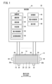
- FIG. 1 is a block diagram of a distribution measurement apparatus according to the first embodiment.
- 2A and 2B are schematic diagrams showing the arrangement of a plurality of electrodes in a first arrangement example.
- 3A and 3B are schematic diagrams showing the arrangement of a plurality of electrodes in the second arrangement example.
- 4A and 4B are schematic diagrams showing the arrangement of one pair of electrodes in the third arrangement example.
- FIG. 5 is a schematic diagram showing the arrangement of one electrode pair in the fourth arrangement example.
- 6A and 6B are schematic diagrams showing the arrangement of a plurality of electrodes in the fifth arrangement example.
- 7A and 7B are schematic diagrams showing the arrangement of a plurality of electrodes in the fifth arrangement example.
- FIG. 8A and 8B are schematic diagrams showing the arrangement of a plurality of electrodes in the sixth arrangement example.
- FIG. 9 is a schematic diagram showing the arrangement of a plurality of electrodes in the seventh arrangement example.
- 10A and 10B are schematic diagrams showing combination patterns of four electrodes in the seventh arrangement example.
- FIG. 11 is a flowchart showing the operation of the distribution measurement apparatus according to the first embodiment.
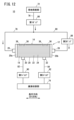
- FIG. 12 is a fluid circuit diagram of the distribution measurement device according to the second embodiment.
- FIG. 13 is a block diagram of a distribution measurement apparatus according to the second embodiment.
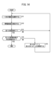
- FIG. 14 is a flowchart showing the operation of the distribution measurement apparatus according to the second embodiment.
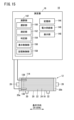
- FIG. 15 is a block diagram of a distribution measurement apparatus according to the third embodiment.
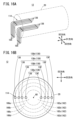
- FIG. 16A and 16B are schematic diagrams showing the arrangement of a plurality of electrodes in the third embodiment.
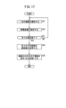
- FIG. 17 is a flowchart showing the operation of the distribution measurement apparatus according to the third embodiment.
- FIG. 18 is a schematic diagram showing the arrangement of a plurality of electrodes in the fourth embodiment.
- 19A and 19B are schematic diagrams showing the arrangement of a plurality of electrodes in the fifth embodiment.
- [1-1 Configuration of distribution measurement device 10] 1 is a block diagram of a distribution measurement device 10 according to the first embodiment.
- the distribution measurement device 10 according to the first embodiment can measure the distribution of cells in the longitudinal direction of a bioreactor 12. Examples of the cells include ES cells, iPS cells, mesenchymal stem cells, and the like. Note that the cells are not limited to the above-mentioned cells, and may be yeast or the like.
- the distribution measurement device 10 includes a bioreactor 12, an electrode group 14, and a measurement device 16.
- the bioreactor 12 is a component of a cell culture device (not shown).
- the bioreactor 12 includes a plurality of hollow fiber membranes 18 and a cylindrical housing 20.
- the plurality of hollow fiber membranes 18 are housed inside the housing 20.
- the longitudinal direction of each hollow fiber membrane 18 is aligned with the longitudinal direction of the bioreactor 12. That is, each hollow fiber membrane 18 extends along the longitudinal direction of the bioreactor 12.
- the hollow fiber membranes 18 are made of, for example, a polymeric material.
- the hollow fiber membranes 18 have a plurality of pores (not shown).
- a first end of each hollow fiber membrane 18 is fixed to a first longitudinal end 20a of the housing 20.
- a second end of each hollow fiber membrane 18 is fixed to a second longitudinal end 20b of the housing 20.
- the bioreactor 12 comprises a first region 22 and a second region 24.
- the first region 22 is the space inside each hollow fiber membrane 18.
- the second region 24 is the space between the outer peripheral surface of each hollow fiber membrane 18 and the inner peripheral surface of the housing 20.
- the first region 22 and the second region 24 are in communication with each other via multiple pores in each hollow fiber membrane 18.
- the housing 20 has a first port 26 (first supply/discharge port), a second port 28 (second supply/discharge port), a third port 30, and a fourth port 32.
- the first port 26 is disposed at the first end 20a of the housing 20.
- the first port 26 is connected to the first end of each hollow fiber membrane 18. As a result, the first port 26 is in communication with the first region 22.
- the second port 28 is disposed at the second end 20b of the housing 20.
- the second port 28 is connected to the second end of each hollow fiber membrane 18. As a result, the second port 28 is in communication with the first region 22.
- the third port 30 and the fourth port 32 are arranged on the outer peripheral surface of the housing 20.
- the third port 30 is arranged between the first port 26 and the longitudinal center of the housing 20.
- the fourth port 32 is arranged between the second port 28 and the longitudinal center of the housing 20.
- Each of the third port 30 and the fourth port 32 is connected to the second region 24.
- a cell suspension containing cells is supplied to the inside of the bioreactor 12 (first region 22) from the first port 26 or the second port 28.
- the culture medium is supplied to the inside of the bioreactor 12 (first region 22) from the first port 26 or the second port 28.
- the culture medium is also supplied to the inside of the bioreactor 12 (second region 24) from the third port 30 or the fourth port 32.
- the culture medium supplied to the bioreactor 12 can move between the first region 22 and the second region 24 through the pores of the hollow fiber membrane 18.
- the electrode group 14 is composed of multiple (three or more) electrodes 36.
- the multiple electrodes 36 are arranged inside the bioreactor 12 along the longitudinal direction of the bioreactor 12. The arrangement of the multiple electrodes 36 will be described later.
- the measuring device 16 is capable of measuring the capacitance (or dielectric constant, omitted below) between a pair of electrodes 36.
- the capacitance between a pair of electrodes 36 is a physical quantity proportional to the cell concentration (cell number, omitted below) between the pair of electrodes 36.
- the measuring device 16 may be, for example, an impedance analyzer, an LCR meter, etc.
- the measuring device 16 includes a calculation unit 42, a memory unit 44, a power supply unit 46, and a display unit 48.
- the calculation unit 42 may be configured, for example, by a processor such as a CPU (Central Processing Unit) or a GPU (Graphics Processing Unit). In other words, the calculation unit 42 may be configured by a processing circuit.
- a processor such as a CPU (Central Processing Unit) or a GPU (Graphics Processing Unit).
- the calculation unit 42 may be configured by a processing circuit.
- the calculation unit 42 includes a selection unit 50, a measurement unit 52, a determination unit 54, a display control unit 56, and a memory control unit 58.
- Each of the selection unit 50, the measurement unit 52, the determination unit 54, the display control unit 56, and the memory control unit 58 can be realized by the calculation unit 42 executing a program stored in the memory unit 44.
- the selection unit 50, the measurement unit 52, the determination unit 54, the display control unit 56, and the memory control unit 58 may be realized by an integrated circuit such as an ASIC (Application Specific Integrated Circuit) or an FPGA (Field-Programmable Gate Array).
- ASIC Application Specific Integrated Circuit
- FPGA Field-Programmable Gate Array
- at least a portion of the selection unit 50, the measurement unit 52, the determination unit 54, the display control unit 56, and the memory control unit 58 may be configured by an electronic circuit including a discrete device.
- the selection unit 50 sequentially selects a pair of electrodes 36 from among the multiple electrodes 36 (electrode group 14).
- the measurement unit 52 performs switching control of the electrodes 36 based on the selection result of the selection unit 50. Furthermore, the measurement unit 52 sequentially measures the capacitance between the pair of electrodes 36 selected by the selection unit 50.
- the determination unit 54 performs various determinations.
- the display control unit 56 performs display control. For example, the display control unit 56 displays information indicating the distribution of cells in the longitudinal direction of the bioreactor 12 on the display unit 48 based on the capacitance measured by the measurement unit 52.
- the memory control unit 58 performs memory control. For example, the memory control unit 58 stores information indicating the distribution of cells in the longitudinal direction of the bioreactor 12 in the memory unit 44 based on the capacitance measured by the measurement unit 52.
- the memory unit 44 may be composed of a volatile memory (not shown) and a non-volatile memory (not shown).
- An example of the volatile memory may be a RAM (Random Access Memory).
- This volatile memory is used as a working memory for the processor, and temporarily stores data and the like required for processing or calculation.
- An example of the non-volatile memory may be a ROM (Read Only Memory), flash memory, and the like.
- This non-volatile memory is used as a storage memory, and stores programs, tables, maps, and the like. At least a portion of the memory unit 44 may be provided in the processor, integrated circuit, etc. as described above.
- the memory unit 44 is capable of storing information indicating the distribution of cells in the longitudinal direction of the bioreactor 12 according to memory control by the memory control unit 58 of the calculation unit 42. Note that a part of the memory unit 44 may be provided outside the measurement device 16.
- the power supply unit 46 includes a power supply circuit capable of applying a voltage (or current) between the pair of electrodes 36.
- the power supply circuit includes a plurality of switches. Each switch switches between connection and disconnection between a power source (not shown) and each electrode 36 in response to a switching signal output from the calculation unit 42 (measurement unit 52).
- the display unit 48 includes a drive circuit and a display.
- the display unit 48 is capable of displaying information indicating the distribution of cells in the longitudinal direction of the bioreactor 12 according to display control by the calculation unit 42 (display control unit 56).
- the display unit 48 may display each cell concentration in a numerical value.
- the display unit 48 may display each cell concentration in a graph.
- the longitudinal direction of the bioreactor 12 will also be referred to as the D1 direction.
- two mutually orthogonal directions will be referred to as the D2 direction and the D3 direction.
- the D2 direction and the D3 direction are orthogonal to the D1 direction.
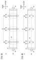
- FIG. 2A and 2B are schematic diagrams showing the arrangement of the multiple electrodes 36 in the first arrangement example.
- Fig. 2A shows the positional relationship between the bioreactor 12 and the multiple electrodes 36 in a plan view of the bioreactor 12.
- Fig. 2B shows the positional relationship between the bioreactor 12 and the multiple electrodes 36 in a front view of the bioreactor 12.
- each electrode 36 extends along a direction D2. That is, each electrode 36 extends along a direction intersecting the direction D1. Each electrode 36 penetrates the housing 20 of the bioreactor 12. Each electrode 36 is insulated with respect to the housing 20. Each electrode 36 is connected to a power supply 46 (FIG. 1).
- two of the multiple electrodes 36 are arranged along the D3 direction. These two electrodes 36 are spaced apart from each other across the axis 60 of the housing 20 (bioreactor 12). When measuring the capacitance, these two electrodes 36 are selected simultaneously. One of the two electrodes 36 is set as a positive electrode, and the other is set as a negative electrode. In other words, when measuring the capacitance, these two electrodes 36 form a pair. In this way, two electrodes 36 that are paired with one electrode 36 in advance, with only one electrode 36 corresponding to each other, are referred to as a "paired electrode 38."
- the electrode group 14 includes multiple paired electrodes 38.
- the multiple paired electrodes 38 are arranged at a distance from each other along the D1 direction. For example, the paired electrodes 38 are arranged at equal intervals along the D1 direction.
- the pair of electrodes 38 When the power supply unit 46 (FIG. 1) applies a voltage (or current) to the pair of electrodes 38 (a pair of electrodes 36), the pair of electrodes 38 stores a charge corresponding to the cell concentration between the electrodes 36.
- the cell concentration is approximately constant within a certain range centered on the pair of electrodes 38.
- the pair of electrodes 38 functions as a sensor member for measuring the cell concentration within a certain range. This certain range is called the measurement range 62.
- the measurement range 62 is determined by the distance between the positive and negative electrodes of the pair of electrodes 38 (interelectrode distance) and the length of each electrode 36. It is preferable that the length and interelectrode distance of each electrode 36 are set so that the measurement range 62 is wide.
- the length and interelectrode distance of each electrode 36 are set so that the measurement range 62 is maximized. Furthermore, it is preferable that the multiple pair of electrodes 38 are arranged along the D1 direction so that two adjacent measurement ranges 62 are as close as possible to each other. By satisfying these conditions, the distribution of cell concentration in the D1 direction in the bioreactor 12 can be measured with a minimum number of electrode pairs 38. However, these conditions are not essential.
- FIG. 3A and 3B are schematic diagrams showing the arrangement of the multiple electrodes 36 in the second arrangement example.
- Fig. 3A shows the positional relationship between the bioreactor 12 and the multiple electrodes 36 in a plan view of the bioreactor 12.
- Fig. 3B shows the positional relationship between the bioreactor 12 and the multiple electrodes 36 in a front view of the bioreactor 12.
- differences from the first arrangement example will be described.
- the arrangement direction of the two electrodes 36 included in one electrode set 38 is different from that of the first arrangement example.
- the multiple electrodes 36 are arranged along the D1 direction.
- all of the electrodes 36 are arranged so as to intersect with the axis 60 of the housing 20.
- all of the electrodes 36 are arranged so as to be perpendicular to the axis 60 of the housing 20.
- all of the electrodes 36 or some of the electrodes 36 may be offset from the axis 60.
- Each electrode 36 forms a pair electrode 38 (positive and negative electrodes) with the most adjacent electrode 36.
- the electrode group 14 includes multiple pair electrodes 38.
- the multiple pair electrodes 38 are arranged spaced apart from each other along the D1 direction.
- the pair electrodes 38 are arranged at equal intervals along the D1 direction.
- [C. Third Arrangement Example] 4A and 4B are schematic diagrams showing the arrangement of one electrode pair 38 in the third arrangement example. 4A and 4B show the positional relationship between the bioreactor 12 and one electrode pair 38 in a side view of the bioreactor 12.
- the third arrangement example is a modified example of the first arrangement example. Regarding the third arrangement example, differences from the first arrangement example will be described. In the third arrangement example, the shape of the two electrodes 36 forming one electrode pair 38 is different from that of the first arrangement example.
- each electrode 36 curves along the inner periphery of the housing 20 of the bioreactor 12.
- the electrodes 36 are attached to the inner periphery of the housing 20.
- the electrodes 36 are insulated from the housing 20.
- the electrodes 36 are connected to the power supply 46 (FIG. 1) via leads 64.
- the leads 64 may extend from both ends of the electrodes 36.
- the leads 64 may extend from a portion of the electrodes 36.
- [D Fourth Arrangement Example] 5 is a schematic diagram showing the arrangement of one electrode group 38 in the fourth arrangement example.
- the fourth arrangement example is a modified example of the first and third arrangement examples.
- the electrode group 38 in the fourth arrangement example includes the electrode group 38 in the first arrangement example (hereinafter referred to as the first electrode group 38a) and the electrode group 38 in the third arrangement example (hereinafter referred to as the third electrode group 38b).
- the first electrode group 38a is disposed between the electrodes of the third electrode group 38b.
- the power supply unit 46 applies a voltage (or current) to the third set of electrodes 38b and measures the capacitance of the first set of electrodes 38a. According to the fourth arrangement example, the effect of the electric double layer can be reduced.
- FIG. 6A, 6B, 7A, and 7B are schematic diagrams showing the arrangement of the multiple electrodes 36 in the fifth arrangement example.
- the fifth arrangement example is a modified example of the second arrangement example.
- the multiple electrodes 36 are arranged at equal intervals along the D1 direction.
- the selection unit 50 (FIG. 1) can select any two electrodes 36.
- the selection unit 50 may sequentially select two adjacent electrodes 36 as a pair of electrodes 36, as shown in FIG. 6B.
- the selection unit 50 may also sequentially select two electrodes 36 that sandwich one or more electrodes 36 as a pair of electrodes 36, as shown in FIG. 7A.
- the selection unit 50 may also sequentially select a pair of electrodes 36 such that multiple measurement ranges 62 overlap, as shown in FIG. 7B.
- the measurement range 62 can be expanded in the D1 direction, the D2 direction, and the D3 direction.
- FIGS. 8A and 8B are schematic diagrams showing the arrangement of the multiple electrodes 36 in the sixth arrangement example.
- Fig. 8A shows the positional relationship between the bioreactor 12 and the multiple electrodes 36 in a plan view of the bioreactor 12.
- Fig. 8B shows the positional relationship between the bioreactor 12 and the multiple electrodes 36 in a front view of the bioreactor 12.
- the housing 20 of the bioreactor 12 has a plurality of protrusions 66.
- Each of the plurality of protrusions 66 protrudes in the same direction (D3 direction) from the outer peripheral surface (e.g., the upper surface) of the housing 20.
- the plurality of protrusions 66 are arranged spaced apart from one another along the D1 direction.
- Each of the protrusions 66 is hollow.
- a lid 68 is detachably attached to the tip of each of the protrusions 66. When attached to the protrusions 66, the lid 68 is parallel to the D2 direction and perpendicular to the D3 direction.
- Two electrodes 36 are arranged on the lid 68. The two electrodes 36 are parallel to each other. For example, each electrode 36 extends along the D2 direction.
- the two electrodes 36 arranged on the lid 68 form a pair of electrodes 38.
- Fig. 9 is a schematic diagram showing the arrangement of the multiple electrodes 36 in the seventh arrangement example.
- Fig. 9 shows the positional relationship between the bioreactor 12 and the multiple electrodes 36 in a front view of the bioreactor 12.
- Figs. 10A and 10B are schematic diagrams showing combination patterns of the four electrodes 36 in the seventh arrangement example.
- the housing 20 of the bioreactor 12 has a plurality of protrusions 66.
- the structure of the protrusions 66 in the seventh arrangement example is the same as the structure of the protrusions 66 in the sixth arrangement example.
- the multiple protrusions 66 are divided into two groups.
- Each of the protrusions 66 in the first group (hereinafter referred to as a first protrusion 66a) protrudes from the upper surface of the housing 20 along the D3 direction.
- Each of the protrusions 66 in the second group (hereinafter referred to as a second protrusion 66b) protrudes from the lower surface of the housing 20 along the D3 direction.
- One first protrusion 66a and one second protrusion 66b are arranged along the D3 direction.
- one of the two electrodes 36 included in the first protrusion 66a and one of the two electrodes 36 included in the second protrusion 66b are arranged along the D3 direction.
- the other of the two electrodes 36 included in the first protrusion 66a and the other of the two electrodes 36 included in the second protrusion 66b are arranged along the D3 direction.
- the selection unit 50 may select two electrodes 36 arranged along the D1 direction as a pair of electrodes 36, as shown in FIG. 10A.
- the selection unit 50 may also select two electrodes 36 arranged along the D3 direction as a pair of electrodes 36, as shown in FIG. 10B.
- FIG. 11 is a flowchart showing the operation of the distribution measurement device 10 (FIG. 1) according to the first embodiment.
- step S1 the selection unit 50 selects a pair of electrodes 36 from among the multiple electrodes 36. For example, as in FIG. 2A, when a pair of electrodes 38 has been formed in advance, the selection unit 50 selects a pair of electrodes 38 for which capacitance measurement has not yet been completed.
- step S2 the measurement unit 52 performs switching control of the power supply unit 46 so that power is supplied to the pair of electrodes 36 selected by the selection unit 50.
- the power supply unit 46 performs switching according to the switching signal output from the measurement unit 52, and applies a voltage between the pair of electrodes 36.
- the measurement unit 52 measures the electrostatic capacitance between the selected pair of electrodes 36.
- step S3 the determination unit 54 determines whether or not the measurement of all capacitances has been completed. If the measurement of all capacitances has been completed (step S3: YES), the process proceeds to step S4. On the other hand, if the measurement of some capacitances has not been completed (step S3: NO), the process returns to step S1.
- the measurement unit 52 converts each capacitance into a cell concentration using a calibration curve showing the relationship between capacitance and cell concentration.
- the memory unit 44 stores the calibration curve in advance.
- the display control unit 56 performs display control to display information showing the distribution of cells in the longitudinal direction (D1 direction) of the bioreactor 12.
- the display unit 48 displays the information showing the distribution of cells in accordance with the display control. For example, the display unit 48 may display a graph or numerical values as the information showing the distribution of cells.
- the memory control unit 58 stores the information showing the distribution of cells in the longitudinal direction (D1 direction) of the bioreactor 12 in the memory unit 44.
- multiple pairs of electrodes 36 form multiple cell concentration measurement ranges 62 along the D1 direction within the bioreactor 12. Therefore, according to the first embodiment, it is possible to measure the distribution of cells in the longitudinal direction of the bioreactor 12. The distribution of cells in the longitudinal direction of the bioreactor 12 contributes to the optimization of cell culture.
- Fig. 12 is a fluid circuit diagram of the distribution measurement device 10 according to the second embodiment.
- Fig. 13 is a block diagram of the distribution measurement device 10 according to the second embodiment.
- the distribution measurement device 10 according to the second embodiment can measure the distribution of cells in the longitudinal direction of the bioreactor 12. Furthermore, when the cells to be cultured are suspension cells, the distribution measurement device 10 according to the second embodiment can change the distribution of cells in the longitudinal direction of the bioreactor 12.
- the distribution measurement device 10 according to the second embodiment may be incorporated into a cell culture device that cultures cells.
- some of the components of the cell culture device may also be used as components of the distribution measurement device 10.
- components that have the same functions as those in the first embodiment are given the same reference numerals, and their description will be omitted.
- the distribution measurement device 10 includes a culture medium supply unit 72 and a waste liquid storage unit 74.
- the culture medium supply unit 72 includes a medical bag filled with culture medium.
- the waste liquid storage unit 74 includes a medical bag that can collect waste liquid discharged from the bioreactor 12.
- the distribution measuring device 10 includes a supply flow path 76, a first branch flow path 78, a second branch flow path 80, a first waste liquid flow path 82, and a second waste liquid flow path 84.
- Each flow path includes a tube through which liquid flows.
- the supply flow path 76 is connected to the culture medium supply section 72, the first branch flow path 78, and the second branch flow path 80.
- the first branch flow path 78 is connected to the supply flow path 76 and the first port 26 of the bioreactor 12.
- the second branch flow path 80 is connected to the supply flow path 76 and the second port 28 of the bioreactor 12.
- the first waste liquid flow path 82 is connected to the third port 30 of the bioreactor 12 and the waste liquid storage section 74.
- the second waste liquid flow path 84 is connected to the fourth port 32 of the bioreactor 12 and the waste liquid storage section 74.
- the distribution measuring device 10 includes a first pump 86 and a second pump 88.
- the first pump 86 is disposed in the supply flow path 76.
- the second pump 88 is disposed in the second branch flow path 80.
- the first pump 86 is capable of imparting a flow force to the culture medium in the supply flow path 76 in a direction toward the first branch flow path 78 and the second branch flow path 80.
- the second pump 88 is capable of imparting a flow force to the culture medium in the second branch flow path 80 in a direction toward the second port 28 or a flow force toward the first port 26.
- the distribution measurement device 10 includes a first valve 90 and a second valve 92.
- the first valve 90 is disposed in the first waste liquid flow path 82.
- the second valve 92 is disposed in the second waste liquid flow path 84.
- the first valve 90 and the second valve 92 include clamps that can open and close the flow paths (tubes).
- the calculation unit 42 is provided with a fluid control unit 98 (control unit).
- the fluid control unit 98 can be realized by the calculation unit 42 executing a program stored in the memory unit 44.
- the fluid control unit 98 outputs various operating signals to control the operation of the first pump 86, the second pump 88, the first valve 90, and the second valve 92.
- the fluid control unit 98 can control at least one of the inflow rate of the culture medium into the bioreactor 12 and the outflow rate of the culture medium from the bioreactor 12.
- the distribution measurement device 10 includes a pump drive circuit 94 and a valve drive circuit 96.
- the pump drive circuit 94 supplies power to the first pump 86 and the second pump 88 in response to an operation signal output from the measuring device 16 (fluid control unit 98).
- the valve drive circuit 96 supplies power to the first valve 90 and the second valve 92 in response to an operation signal output from the measuring device 16 (fluid control unit 98).
- Fig. 14 is a flowchart showing the operation of the distribution measurement device 10 according to the second embodiment.
- the series of processes shown in Fig. 14 may be included in a cell culture process.
- a cell agitation process for agitating the cells inside the bioreactor 12 a cell packing process for packing the cells remaining in the flow path inside the bioreactor 12, and a cell culture process for culturing the cells are repeatedly performed.
- the series of processes shown in FIG. 14 may be performed in a cell packing process.
- culture medium is supplied from the culture medium supply unit 72 to the bioreactor 12 via the supply flow path 76 and the first branch flow path 78.
- culture medium is supplied from the culture medium supply unit 72 to the bioreactor 12 via the supply flow path 76 and the second branch flow path 80.
- the cells remaining in the first branch flow path 78 and the second branch flow path 80 are packed inside the bioreactor 12.
- Steps S11 to S13 shown in FIG. 14 are the same as steps S1 to S3 shown in FIG. 11. Therefore, the explanation of steps S11 to S13 will be omitted here.
- step S13 when all capacitance measurements have been completed (step S13: YES), the process proceeds to step S14.
- the judgment unit 54 judges whether each measured capacitance is within a predetermined range.
- the predetermined range is set based on the cell concentration in a state in which the cells are uniformly dispersed inside the bioreactor 12.
- the cell concentration in a state in which the cells are uniformly dispersed is referred to as a reference value.
- the predetermined range is set to a range between an upper limit value that is a predetermined value higher than the reference value and a lower limit value that is a predetermined value lower than the reference value.
- the memory unit 44 stores the predetermined range in advance.
- step S14 If each capacitance is within the predetermined range (step S14: YES), the series of processes shown in FIG. 14 ends. In this case, the cell concentration at each position along the longitudinal direction of the bioreactor 12 is approximately uniform. On the other hand, if at least one capacitance is outside the predetermined range (step S14: NO), the process proceeds to step S15. In this case, the cell concentration at each position along the length of the bioreactor 12 is non-uniform.
- the fluid control unit 98 controls each pump and each valve so that the cell concentration at each position along the longitudinal direction of the bioreactor 12 is uniform.
- the cell concentration near the first port 26 may be higher than the cell concentration near the second port 28.
- the fluid control unit 98 controls the first pump 86 and the second pump 88 so that the inflow rate of the culture medium to the first port 26 is greater than the inflow rate of the culture medium to the second port 28.
- the flow force from the first port 26 to the second port 28 is greater than the flow force from the second port 28 to the first port 26.
- the fluid control unit 98 closes the first valve 90 and opens the second valve 92. Then, inside the bioreactor 12, some of the cells that diffuse near the first port 26 move toward the second port 28. As a result, the bias in the cell concentration inside the bioreactor 12 is corrected.
- the excess culture medium inside the bioreactor 12 is discharged to the waste liquid storage unit 74 via the second waste liquid flow path 84.
- the cell concentration near the second port 28 may be higher than the cell concentration near the first port 26.
- the fluid control unit 98 controls the first pump 86 and the second pump 88 so that the inflow rate of the culture medium to the second port 28 is greater than the inflow rate of the culture medium to the first port 26.
- the flow force from the second port 28 to the first port 26 is greater than the flow force from the first port 26 to the second port 28.
- the fluid control unit 98 closes the second valve 92 and opens the first valve 90. Then, inside the bioreactor 12, some of the cells that diffuse near the second port 28 move toward the first port 26. As a result, the bias in the cell concentration inside the bioreactor 12 is corrected.
- the excess culture medium inside the bioreactor 12 is discharged to the waste liquid storage unit 74 via the first waste liquid flow path 82.
- step S11 onwards is executed again. For example, if the amount of culture medium supplied in step S15 exceeds a predetermined amount, or if the execution time of step S15 exceeds a predetermined time, the processing from step S11 onwards is executed again.
- the fluid control unit 98 controls each pump and each valve based on the cell distribution so that the cells are distributed uniformly in the longitudinal direction of the bioreactor 12.
- the second embodiment can contribute to the optimization of cell culture.
- [3 Third embodiment] [3-1 Configuration of distribution measuring device 10] 15 is a block diagram of a distribution measurement device 10 according to the third embodiment.
- the distribution measurement device 10 according to the third embodiment can measure the distribution of cells in a direction intersecting the longitudinal direction of the bioreactor 12. Examples of the cells include ES cells, iPS cells, mesenchymal stem cells, and the like. Note that the cells are not limited to the above-mentioned cells, and may be yeast or the like.
- the distribution measurement device 10 includes a bioreactor 12, an electrode group 114, and a measurement device 16.
- the electrode group 114 is composed of multiple (three or more) electrodes 136.
- Each electrode 136 is disposed inside the bioreactor 12.
- the longitudinal direction of each electrode 136 is aligned with the longitudinal direction of the bioreactor 12. In other words, each electrode 136 extends along the longitudinal direction of the bioreactor 12. The arrangement of the multiple electrodes 136 will be described later.
- the measuring device 16 is capable of measuring the capacitance (or dielectric constant, omitted below) between the pair of electrodes 136.
- the capacitance between the pair of electrodes 136 is a physical quantity proportional to the cell concentration (cell number, omitted below) between the pair of electrodes 136.
- the measuring device 16 may be, for example, an impedance analyzer, an LCR meter, etc.
- the measuring device 16 includes a calculation unit 142, a memory unit 144, a power supply unit 146, and a display unit 148.
- the calculation unit 142 may be configured, for example, by a processor such as a CPU (Central Processing Unit) or a GPU (Graphics Processing Unit). In other words, the calculation unit 142 may be configured by a processing circuit.
- a processor such as a CPU (Central Processing Unit) or a GPU (Graphics Processing Unit).
- the calculation unit 142 may be configured by a processing circuit.
- the calculation unit 142 includes a selection unit 150, a measurement unit 152, a determination unit 154, a display control unit 156, and a memory control unit 158.
- Each of the selection unit 150, the measurement unit 152, the determination unit 154, the display control unit 156, and the memory control unit 158 can be realized by the calculation unit 142 executing a program stored in the memory unit 144.
- the selection unit 150, the measurement unit 152, the determination unit 154, the display control unit 156, and the memory control unit 158 may be realized by an integrated circuit such as an ASIC (Application Specific Integrated Circuit) or an FPGA (Field-Programmable Gate Array).
- ASIC Application Specific Integrated Circuit
- FPGA Field-Programmable Gate Array
- at least a portion of the selection unit 150, the measurement unit 152, the determination unit 154, the display control unit 156, and the memory control unit 158 may be configured by an electronic circuit including a discrete device.
- the selection unit 150 sequentially selects a pair of electrodes 136 from among the multiple electrodes 136 (electrode group 114).
- the measurement unit 152 performs switching control of the electrodes 136 based on the selection result of the selection unit 150. Furthermore, the measurement unit 152 sequentially measures the capacitance between the pair of electrodes 136 selected by the selection unit 150.
- the determination unit 154 performs various determinations.
- the display control unit 156 performs display control. For example, the display control unit 156 displays information indicating the distribution of cells in a direction intersecting the longitudinal direction of the bioreactor 12 on the display unit 148 based on the capacitance measured by the measurement unit 152.
- the memory control unit 158 performs memory control. For example, the memory control unit 158 stores information indicating the distribution of cells in a direction intersecting the longitudinal direction of the bioreactor 12 in the memory unit 144 based on the capacitance measured by the measurement unit 152.
- the memory unit 144 may be composed of a volatile memory (not shown) and a non-volatile memory (not shown).
- An example of the volatile memory may be a RAM (Random Access Memory).
- This volatile memory is used as a working memory for the processor, and temporarily stores data and the like required for processing or calculation.
- An example of the non-volatile memory may be a ROM (Read Only Memory), flash memory, and the like.
- This non-volatile memory is used as a storage memory, and stores programs, tables, maps, and the like. At least a portion of the memory unit 144 may be provided in the processor, integrated circuit, etc. as described above.
- the memory unit 144 is capable of storing information indicating the distribution of cells in a direction intersecting the longitudinal direction of the bioreactor 12 according to memory control by the memory control unit 158 of the calculation unit 142. Note that a part of the memory unit 144 may be provided outside the measurement device 16.
- the power supply unit 146 includes a power supply circuit capable of applying a voltage (or current) between the pair of electrodes 136.
- the power supply circuit includes a plurality of switches. Each switch switches between connection and disconnection between a power source (not shown) and each electrode 136 in response to a switching signal output from the calculation unit 142 (measurement unit 152).
- the display unit 148 includes a drive circuit and a display.
- the display unit 148 is capable of displaying information indicating the distribution of cells in a direction intersecting the longitudinal direction of the bioreactor 12 according to display control by the calculation unit 142 (display control unit 156).
- the display unit 148 may display each cell concentration in a numerical value.
- the display unit 148 may display each cell concentration in a graph.
- Electrodes 136 The arrangement of the multiple electrodes 136 (electrode group 114) will be described below.
- the longitudinal direction of the bioreactor 12 will also be referred to as the D1 direction.
- two mutually orthogonal directions will be referred to as the D2 direction and the D3 direction.
- the D2 direction and the D3 direction are orthogonal to the D1 direction.
- FIG. 16A and 16B are schematic diagrams showing the arrangement of multiple electrodes 136 in the third embodiment. As shown in FIG. 16A, each electrode 136 extends along the D1 direction. Each electrode 136 is arranged at the same position with respect to the D1 direction. Each electrode 136 is connected to a power supply unit 146 (FIG. 15) via a lead wire 164. As shown in FIG. 16B, the distance from each of two electrodes 136 among the multiple electrodes 136 to the axis 60 of the housing 20 (bioreactor 12) is equal. These two electrodes 136 are spaced apart from each other with the axis 60 of the housing 20 in between.
- these two electrodes 136 and the axis 60 of the housing 20 are arranged along the radial direction (e.g., the D3 direction) of the housing 20 (bioreactor 12).
- these two electrodes 136 are selected simultaneously.
- One of the two electrodes 136 is a positive electrode, and the other is a negative electrode.
- these two electrodes 136 form a pair when measuring the capacitance.
- two electrodes 136 that are paired with one electrode 136 in advance are referred to as a "paired electrode 138."
- paired electrode 138 Inside the bioreactor 12, multiple paired electrodes 138 with different distances between the electrodes 136 (inter-electrode distance) are provided.
- the multiple electrode pairs 138 are arranged along the same direction (D3 direction). That is, the multiple electrodes 136 are arranged along a direction (D3 direction) perpendicular to the longitudinal direction (D1 direction) of the bioreactor 12. Note that the multiple electrodes 136 may be arranged along a direction intersecting the longitudinal direction (D1 direction) of the bioreactor 12 other than the D3 direction.
- the electrode pair 138 When the power supply unit 146 (FIG. 15) applies a voltage (or current) to the electrode pair 138 (pair of electrodes 136), the electrode pair 138 stores an electric charge according to the cell concentration between the electrodes 136.
- the cell concentration is approximately constant within a certain range centered on the electrode pair 138.
- the electrode pair 138 functions as a sensor member for measuring the cell concentration within a certain range.
- This certain range is referred to as the measurement range 162.
- the measurement range 162 is approximately circular in shape centered on the axis 60 of the housing 20 in a side view.
- each electrode 136 is arranged on one of four concentric circles centered on the axis 60 of the housing 20.
- Each electrode 136 included in the first electrode pair 138a is arranged on the circle with the smallest diameter.
- the inter-electrode distance of the first electrode pair 138a is the smallest among the inter-electrode distances of the four electrode pairs 138.
- Each electrode 136 included in the second electrode pair 138b is arranged on the circle with the second smallest diameter.
- the inter-electrode distance of the second electrode pair 138b is the second smallest among the inter-electrode distances of the four electrode pairs 138.
- Each electrode 136 included in the third electrode pair 138c is arranged on the circle with the third smallest diameter. That is, the inter-electrode distance of the third electrode group 138c is the third smallest among the inter-electrode distances of the four electrode group 138.
- Each electrode 136 included in the fourth electrode group 138d is arranged on a circle with the largest diameter. That is, the inter-electrode distance of the fourth electrode group 138d is the largest among the inter-electrode distances of the four electrode group 138.
- Each electrode 136 of the fourth electrode group 138d may contact the inner peripheral surface of the housing 20.
- the measurement range 162 (first measurement range 162a) of the first electrode pair 138a is the smallest.
- the measurement range 162 (second measurement range 162b) of the second electrode pair 138b is one size larger than the first measurement range 162a.
- the measurement range 162 (third measurement range 162c) of the third electrode pair 138c is one size larger than the second measurement range 162b.
- the measurement range 162 (fourth measurement range 162d) of the fourth electrode pair 138d is one size larger than the third measurement range 162c.
- the first measurement range 162a is also referred to as the first distribution range 166a.
- the range of the second measurement range 162b other than the first measurement range 162a is referred to as the second distribution range 166b.
- the range of the third measurement range 162c other than the second measurement range 162b is referred to as the third distribution range 166c.
- the range of the fourth measurement range 162d other than the third measurement range 162c is referred to as the fourth distribution range 166d.
- the cell concentrations in these four distribution regions indicate the distribution of cells in a cross section perpendicular to the longitudinal direction of the bioreactor 12.
- the number of cells in each measurement range 162 can be obtained by the capacitance in each measurement range 162.
- the number of cells in the first distribution range 166a can be obtained by the capacitance in the first measurement range 162a.
- the number of cells in the second distribution range 166b can be obtained by subtracting the number of cells in the first measurement range 162a from the number of cells in the second measurement range 162b.
- the number of cells in the third distribution range 166c can be obtained by subtracting the number of cells in the second measurement range 162b from the number of cells in the third measurement range 162c.
- the number of cells in the fourth distribution range 166d can be obtained by subtracting the number of cells in the third measurement range 162c from the number of cells in the fourth measurement range 162d.
- FIG. 17 is a flowchart showing the operation of the distribution measurement device 10 according to the third embodiment.
- step S21 the selection unit 150 selects a pair of electrodes 136 from among the multiple electrodes 136. For example, as shown in FIG. 16B, when a pair of electrodes 138 has been formed in advance, the selection unit 150 selects a pair of electrodes 138 for which capacitance measurement has not yet been completed.
- step S22 the measurement unit 152 performs switching control of the power supply unit 146 so that power is supplied to the pair of electrodes 136 selected by the selection unit 150.
- the power supply unit 146 performs switching according to the switching signal output from the measurement unit 152, and applies a voltage between the pair of electrodes 136.
- the measurement unit 152 measures the electrostatic capacitance between the selected pair of electrodes 136.
- step S23 the determination unit 154 determines whether or not the measurement of all capacitances has been completed. If the measurement of all capacitances has been completed (step S23: YES), the process proceeds to step S24. On the other hand, if the measurement of some capacitances has not been completed (step S23: NO), the process returns to step S21.
- the longitudinal direction of the electrodes 136 for measuring capacitance is aligned with the longitudinal direction of the bioreactor 12. According to the third embodiment, by sequentially switching the combination of electrodes 136, it is possible to measure the distribution of cells in a direction intersecting the longitudinal direction of the bioreactor 12. The distribution of cells in a direction intersecting the longitudinal direction of the bioreactor 12 contributes to the optimization of cell culture.
- Fig. 18 is a schematic diagram showing the arrangement of a plurality of electrodes 136 in the fourth embodiment. As shown in Fig. 18, a plurality of electrodes 136 (a plurality of sets of electrodes 138) may be arranged at each of a plurality of positions in the longitudinal direction (direction D1) of the bioreactor 12.
- FIGS. 19A and 19B are schematic diagrams showing the arrangement of a plurality of electrodes 136 in the fifth embodiment.
- the electrode group 114 includes eight small electrode groups 170.
- Each of the eight small electrode groups 170 includes a plurality of electrodes 136.
- each small electrode group 170 includes four electrodes 136.
- the longitudinal direction of each electrode 136 is aligned with the longitudinal direction of the bioreactor 12. That is, each electrode 136 extends along the longitudinal direction of the bioreactor 12.
- Each electrode 136 is connected to a power supply unit 146 (Fig. 15).
- Each electrode 136 is disposed at the same position in the D1 direction.
- each small electrode group 170 the multiple electrodes 136 and the axis 60 of the housing 20 are arranged along the radial direction of the housing 20 (bioreactor 12).
- the arrangement direction of each small electrode group 170 is shifted by 45 degrees around the axis 60 of the housing 20 with respect to the arrangement direction of the adjacent small electrode group 170.
- the pair of electrodes 136 can be formed in various combinations. Therefore, according to the fifth embodiment, the distribution of cells in a direction intersecting the longitudinal direction of the bioreactor 12 can be measured in more detail than in the third embodiment.
- the present invention is not limited to the above disclosure, and various configurations may be adopted without departing from the gist of the present invention.
Landscapes
- Chemical & Material Sciences (AREA)
- Health & Medical Sciences (AREA)
- Engineering & Computer Science (AREA)
- Life Sciences & Earth Sciences (AREA)
- Zoology (AREA)
- Bioinformatics & Cheminformatics (AREA)
- Organic Chemistry (AREA)
- Wood Science & Technology (AREA)
- Analytical Chemistry (AREA)
- General Health & Medical Sciences (AREA)
- Biochemistry (AREA)
- Biomedical Technology (AREA)
- Sustainable Development (AREA)
- General Engineering & Computer Science (AREA)
- Microbiology (AREA)
- Genetics & Genomics (AREA)
- Biotechnology (AREA)
- Computer Hardware Design (AREA)
- Clinical Laboratory Science (AREA)
- Chemical Kinetics & Catalysis (AREA)
- Electrochemistry (AREA)
- Physics & Mathematics (AREA)
- General Physics & Mathematics (AREA)
- Immunology (AREA)
- Pathology (AREA)
- Apparatus Associated With Microorganisms And Enzymes (AREA)
Priority Applications (4)
| Application Number | Priority Date | Filing Date | Title |
|---|---|---|---|
| EP24763948.7A EP4671353A1 (en) | 2023-02-28 | 2024-02-28 | DISTRIBUTION MEASUREMENT DEVICE |
| CN202480015086.7A CN120813678A (zh) | 2023-02-28 | 2024-02-28 | 分布测定装置 |
| JP2025503951A JPWO2024181469A1 (https=) | 2023-02-28 | 2024-02-28 | |
| US19/310,074 US20250376655A1 (en) | 2023-02-28 | 2025-08-26 | Distribution Measurement Device |
Applications Claiming Priority (4)
| Application Number | Priority Date | Filing Date | Title |
|---|---|---|---|
| JP2023-029016 | 2023-02-28 | ||
| JP2023-029014 | 2023-02-28 | ||
| JP2023029014 | 2023-02-28 | ||
| JP2023029016 | 2023-02-28 |
Related Child Applications (1)
| Application Number | Title | Priority Date | Filing Date |
|---|---|---|---|
| US19/310,074 Continuation US20250376655A1 (en) | 2023-02-28 | 2025-08-26 | Distribution Measurement Device |
Publications (1)
| Publication Number | Publication Date |
|---|---|
| WO2024181469A1 true WO2024181469A1 (ja) | 2024-09-06 |
Family
ID=92589799
Family Applications (1)
| Application Number | Title | Priority Date | Filing Date |
|---|---|---|---|
| PCT/JP2024/007194 Ceased WO2024181469A1 (ja) | 2023-02-28 | 2024-02-28 | 分布測定装置 |
Country Status (5)
| Country | Link |
|---|---|
| US (1) | US20250376655A1 (https=) |
| EP (1) | EP4671353A1 (https=) |
| JP (1) | JPWO2024181469A1 (https=) |
| CN (1) | CN120813678A (https=) |
| WO (1) | WO2024181469A1 (https=) |
Citations (5)
| Publication number | Priority date | Publication date | Assignee | Title |
|---|---|---|---|---|
| WO2016013395A1 (ja) * | 2014-07-22 | 2016-01-28 | 株式会社日立ハイテクノロジーズ | 細胞分散計測機構及びそれを用いた細胞継代培養システム |
| JP2018126104A (ja) * | 2017-02-09 | 2018-08-16 | 株式会社ティ・アンド・シー・テクニカル | 細胞密度測定方法及び細胞密度変化追跡方法 |
| JP2021016359A (ja) * | 2019-07-22 | 2021-02-15 | 株式会社カネカ | 情報処理装置、細胞培養システム、情報処理方法、及びコンピュータプログラム |
| WO2022065401A1 (ja) * | 2020-09-25 | 2022-03-31 | 昭和電工マテリアルズ株式会社 | 細胞培養装置、及び、細胞群を生産する方法 |
| JP2023144814A (ja) * | 2022-03-28 | 2023-10-11 | テルモ株式会社 | 細胞培養装置及び校正方法 |
-
2024
- 2024-02-28 JP JP2025503951A patent/JPWO2024181469A1/ja active Pending
- 2024-02-28 EP EP24763948.7A patent/EP4671353A1/en active Pending
- 2024-02-28 CN CN202480015086.7A patent/CN120813678A/zh active Pending
- 2024-02-28 WO PCT/JP2024/007194 patent/WO2024181469A1/ja not_active Ceased
-
2025
- 2025-08-26 US US19/310,074 patent/US20250376655A1/en active Pending
Patent Citations (6)
| Publication number | Priority date | Publication date | Assignee | Title |
|---|---|---|---|---|
| WO2016013395A1 (ja) * | 2014-07-22 | 2016-01-28 | 株式会社日立ハイテクノロジーズ | 細胞分散計測機構及びそれを用いた細胞継代培養システム |
| JP2018126104A (ja) * | 2017-02-09 | 2018-08-16 | 株式会社ティ・アンド・シー・テクニカル | 細胞密度測定方法及び細胞密度変化追跡方法 |
| JP6381083B2 (ja) | 2017-02-09 | 2018-08-29 | 株式会社ティ・アンド・シー・テクニカル | 細胞密度測定方法及び細胞密度変化追跡方法 |
| JP2021016359A (ja) * | 2019-07-22 | 2021-02-15 | 株式会社カネカ | 情報処理装置、細胞培養システム、情報処理方法、及びコンピュータプログラム |
| WO2022065401A1 (ja) * | 2020-09-25 | 2022-03-31 | 昭和電工マテリアルズ株式会社 | 細胞培養装置、及び、細胞群を生産する方法 |
| JP2023144814A (ja) * | 2022-03-28 | 2023-10-11 | テルモ株式会社 | 細胞培養装置及び校正方法 |
Non-Patent Citations (1)
| Title |
|---|
| See also references of EP4671353A1 |
Also Published As
| Publication number | Publication date |
|---|---|
| US20250376655A1 (en) | 2025-12-11 |
| EP4671353A1 (en) | 2025-12-31 |
| JPWO2024181469A1 (https=) | 2024-09-06 |
| CN120813678A (zh) | 2025-10-17 |
Similar Documents
| Publication | Publication Date | Title |
|---|---|---|
| EP2193100B1 (en) | pH gradients controlled by electrolysis, and their use in isoelectric focusing | |
| WO2024181469A1 (ja) | 分布測定装置 | |
| CN205844251U (zh) | 检测电极结构以及检测孔板 | |
| KR20110116008A (ko) | 샘플 중의 하전된 종의 농도를 측정하기 위한 장치 | |
| US4789435A (en) | Method and device of measuring ion activity | |
| TWI660171B (zh) | 電性化學測定裝置及轉換器 | |
| CN207351949U (zh) | 一种集成式流通池模块 | |
| JP2023144814A (ja) | 細胞培養装置及び校正方法 | |
| CN116183697A (zh) | 一种全固态型氯离子选择性电极及其制备方法与在血气分析检测中的应用 | |
| Canali et al. | Impedance-based monitoring for tissue engineering applications | |
| RU201075U1 (ru) | Датчик кондуктометрический двухэлектродный | |
| CN223949431U (zh) | 一种辅助灌装机高位槽液面稳定的装置 | |
| WO2022044555A1 (ja) | 細胞培養容器及び細胞培養システム | |
| US20180209934A1 (en) | Electrochemical Measuring Cell for Measuring the Content of Chlorine Compounds in Water | |
| WO2023127453A1 (en) | Simulation apparatus, simulation system, and simulation method | |
| US11567027B2 (en) | Analysis of a test sample | |
| SU1657145A1 (ru) | Электродное устройство дл измерени биопотенциалов | |
| Cosofret et al. | Calcium selective polymeric membranes for microfabricated sensor arrays | |
| JP2009069025A (ja) | 隔膜式過酸化水素電極 | |
| EP4488380A1 (en) | Cell culture device and calibration method | |
| WO2023054081A1 (en) | Cell culturing device and cell culturing system | |
| SU568907A1 (ru) | Устройство дл измерени электрических параметров биологических суспензий на низких частотах | |
| JP4723891B2 (ja) | ハイブリダイゼーション用カートリッジ、ハイブリダイゼーション装置およびハイブリダイゼーション方法 | |
| CN108061811B (zh) | 方便培植液置换的生物传感器 | |
| SU1474535A1 (ru) | Электрохимическа чейка дл потенциометрического измерени концентрации ионов |
Legal Events
| Date | Code | Title | Description |
|---|---|---|---|
| 121 | Ep: the epo has been informed by wipo that ep was designated in this application |
Ref document number: 24763948 Country of ref document: EP Kind code of ref document: A1 |
|
| WWE | Wipo information: entry into national phase |
Ref document number: 2025503951 Country of ref document: JP |
|
| WWE | Wipo information: entry into national phase |
Ref document number: 202480015086.7 Country of ref document: CN |
|
| WWE | Wipo information: entry into national phase |
Ref document number: 2024763948 Country of ref document: EP |
|
| NENP | Non-entry into the national phase |
Ref country code: DE |
|
| WWP | Wipo information: published in national office |
Ref document number: 202480015086.7 Country of ref document: CN |
|
| ENP | Entry into the national phase |
Ref document number: 2024763948 Country of ref document: EP Effective date: 20250926 |
|
| ENP | Entry into the national phase |
Ref document number: 2024763948 Country of ref document: EP Effective date: 20250926 |
|
| WWP | Wipo information: published in national office |
Ref document number: 2024763948 Country of ref document: EP |