WO2024181306A1 - コネクタ - Google Patents
コネクタ Download PDFInfo
- Publication number
- WO2024181306A1 WO2024181306A1 PCT/JP2024/006557 JP2024006557W WO2024181306A1 WO 2024181306 A1 WO2024181306 A1 WO 2024181306A1 JP 2024006557 W JP2024006557 W JP 2024006557W WO 2024181306 A1 WO2024181306 A1 WO 2024181306A1
- Authority
- WO
- WIPO (PCT)
- Prior art keywords
- terminal
- connector
- housing
- embedded
- case
- Prior art date
- Legal status (The legal status is an assumption and is not a legal conclusion. Google has not performed a legal analysis and makes no representation as to the accuracy of the status listed.)
- Ceased
Links
Images



Classifications
-
- H—ELECTRICITY
- H01—ELECTRIC ELEMENTS
- H01R—ELECTRICALLY-CONDUCTIVE CONNECTIONS; STRUCTURAL ASSOCIATIONS OF A PLURALITY OF MUTUALLY-INSULATED ELECTRICAL CONNECTING ELEMENTS; COUPLING DEVICES; CURRENT COLLECTORS
- H01R13/00—Details of coupling devices of the kinds covered by groups H01R12/70 or H01R24/00 - H01R33/00
- H01R13/40—Securing contact members in or to a base or case; Insulating of contact members
- H01R13/405—Securing in non-demountable manner, e.g. moulding, riveting
-
- H—ELECTRICITY
- H01—ELECTRIC ELEMENTS
- H01R—ELECTRICALLY-CONDUCTIVE CONNECTIONS; STRUCTURAL ASSOCIATIONS OF A PLURALITY OF MUTUALLY-INSULATED ELECTRICAL CONNECTING ELEMENTS; COUPLING DEVICES; CURRENT COLLECTORS
- H01R43/00—Apparatus or processes specially adapted for manufacturing, assembling, maintaining, or repairing of line connectors or current collectors or for joining electric conductors
- H01R43/20—Apparatus or processes specially adapted for manufacturing, assembling, maintaining, or repairing of line connectors or current collectors or for joining electric conductors for assembling or disassembling contact members with insulating base, case or sleeve
- H01R43/24—Assembling by moulding on contact members
Definitions
- This disclosure relates to connectors.
- the connector is composed of, for example, terminals (terminal fittings) and a housing that holds the terminals.
- the connector housing is formed, for example, by insert molding with the terminals as insert parts (Patent Documents 1 to 3).
- the terminals When forming a housing by insert molding using terminals as insert parts, the terminals are placed in a set position in the hollow part (cavity) of the mold, and softened and molten resin is injected (injection filling) into the cavity through a gate on the mold. At this time, the terminals placed in the cavity are subjected to force (pressure) from the injected resin. If the terminals become misaligned or deformed due to the force from the resin, there is a risk of reduced alignment accuracy.
- a core In order to prevent a decrease in alignment accuracy, it is possible to use a core. That is, first, the terminal is used as an insert item and a first insert molding is performed to form a core (primary molded item) that holds the terminal. After that, a second insert molding is performed using the terminal held by the core as an insert item to form a housing (secondary molded item), which is the final molded item. In this way, because the terminal is held by the core during the second insert molding, the terminal is less likely to shift or deform even when subjected to force from the resin, and alignment accuracy is more likely to be guaranteed.
- the present disclosure therefore aims to provide technology that can prevent a decrease in alignment accuracy without using a core.
- the connector disclosed herein is a connector that is attached to a case and electrically connects a device placed inside the case to a device placed outside the case, and includes a terminal and a resin housing that is integrated with the terminal by insert molding, and at least one corner of at least a portion of the terminal that is embedded in the housing has a rounded radius.
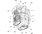
- FIG. 1 is a view of a connector according to an embodiment as viewed obliquely from above.
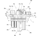
- FIG. 2 is a view of the connector as seen obliquely from below.
- FIG. 3 is a side view of the connector.
- FIG. 4 is a top view of the connector.
- FIG. 5 is a view of the terminal as viewed obliquely from below.
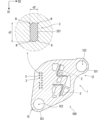
- FIG. 6 is a diagram showing the connector cut at the position where the flange is formed.
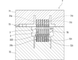
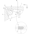
- FIG. 7 is a schematic diagram showing a side cross section of a mold.
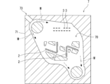
- FIG. 8 is a schematic diagram showing a plan cross section of a mold.
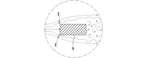
- FIG. 9 is a schematic diagram for explaining the flow of resin formed around the terminal.
- FIG. 10 is a schematic diagram for explaining the flow of resin formed around a terminal that is not provided with a rounded shape.
- a connector that is attached to a case and electrically connects a device placed inside the case to a device placed outside the case, the connector comprising a terminal and a resin housing that is integrated with the terminal by insert molding, and at least one corner of at least a portion of the terminal that is embedded in the housing has a rounded radius.
- the terminal which is the insert product, is placed in the flow of resin. If at least one corner of at least a portion of the portion of the terminal that is embedded in the housing has a rounded radius, the flow of resin is less likely to be disturbed than if the corner were a right angle. This keeps the pressure resistance experienced by the terminal small. As a result, the terminal is less likely to shift or deform, and a decrease in alignment precision can be suppressed even without using a core.
- the terminal may have a bent portion provided midway through the portion embedded in the housing. Providing a bent portion midway through the terminal increases the degree of freedom in designing the connector.
- the at least one corner of the terminal may be rounded over the entire portion embedded in the housing. In this case, the flow of resin is less likely to be disturbed over the entire extension direction of the terminal. This reduces the pressure resistance experienced by the terminal over the entire extension direction. This sufficiently prevents deterioration of alignment accuracy.
- the terminal may have a flat shape in at least a portion of the portion embedded in the housing, in a cross section perpendicular to the extension direction of the terminal, with a dimension in a first direction longer than a dimension in a second direction perpendicular to the first direction.
- a terminal has increased strength (rigidity) by increasing the dimension in the first direction relative to the dimension in the second direction. Therefore, the terminal is less likely to shift or deform. Also, because only the dimension in the first direction is increased, the area of the face as viewed from the first direction is not increased. Therefore, the force that the terminal receives from the first direction is less likely to increase.
- the gate mark of the housing may be located closer to one side in the first direction than the terminal.
- the gate mark being located closer to one side in the first direction than the terminal means that the gate was located closer to one side in the first direction than the terminal during insert molding. In this case, the projected area of the terminal as seen from the gate position is kept small. Therefore, even if the dimension in the first direction is increased relative to the dimension in the second direction, the force that the terminal receives from the resin is unlikely to increase.
- the housing may include a terminal accommodating portion that accommodates the end of the terminal that is exposed from the housing, and the terminal accommodating portion may be attached in a manner that covers the mating connector. In this case, the range of use of the connector may be expanded.
- FIG. 1 is a view of the connector 100 seen obliquely from above.
- Fig. 2 is a view of the connector 100 seen obliquely from below.
- Fig. 3 is a view of the connector 100 seen from the side.
- Fig. 4 is a view of the connector 100 seen from above. Note that, in this example, when the connector 100 is attached to the case 200, the side that is disposed inside the case 200 is referred to as "upper", and the side that is disposed outside the case 200 is referred to as "lower”. This is for convenience of explanation, and does not stipulate the usage posture of the connector 100.
- the connector 100 electrically connects two devices. Specifically, the connector 100 is attached to a case 200, and electrically connects a device (not shown) located inside the case 200 with a device (not shown) located outside the case 200. Such a connector 100 is also called a relay connector.
- the case 200 to which the connector 100 is attached is assumed to be a case in which oil (e.g., oil for lubrication, cooling, etc.) is sealed inside (one example is the case of a transmission for a vehicle such as an automobile).
- oil e.g., oil for lubrication, cooling, etc.
- the connector 100 comprises a housing 1, multiple (two in the illustrated example) bus bars 2, and multiple (thirteen in the illustrated example) terminals (metal terminals) 3.
- the housing 1 is a resin member integrated with the bus bars 2 and the terminals 3 by insert molding.
- Various resins can be used as a material for forming the housing 1.
- PPS polyphenylene sulfide
- PPS polyphenylene sulfide
- the housing 1 includes a partition portion 11, a flange 12, two busbar accommodating portions (first busbar accommodating portion 13a and second busbar accommodating portion 13b), and two terminal accommodating portions (first terminal accommodating portion 14a and second terminal accommodating portion 14b).
- the partition wall portion 11 is a portion that is inserted into a mounting hole 201 provided in the case 200.
- the mounting hole 201 is, for example, circular in plan view, and in this case, the partition wall portion 11 is cylindrical.
- An annular seal member 4 is provided on the outer peripheral surface of the partition wall portion 11.
- the seal member 4 is formed, for example, of an O-ring (annular packing).
- the seal member 4 seals the gap between the partition wall portion 11 and the mounting hole 201.
- a portion of each bus bar 2 and each terminal 3 in the extension direction is embedded in the partition wall portion 11. That is, each bus bar 2 and each terminal 3 is integrated with the partition wall portion 11 by having a portion of their extension direction embedded in the partition wall portion 11.
- the flange 12 is provided at one end (upper end) of the bulkhead 11.
- the flange 12 has a pair of overhanging portions 121, 121 that overhang outward in the circumferential direction of the bulkhead 11.
- the pair of overhanging portions 121, 121 are provided at positions facing each other.
- a through hole 122 is formed in each overhanging portion 121, into which a cylindrical collar 123 is fitted.
- the first busbar accommodating portion 13a and the first terminal accommodating portion 14a are provided on the end face 10a on one side (upper side) of the bulkhead portion 11, that is, on the end face 10a that is disposed inside the case 200 when the connector 100 is attached to the case 200.
- the first busbar accommodating portion 13a is, for example, a U-shaped frame in a plan view.
- the first terminal accommodating portion 14a is, for example, a cylindrical shape (as an example, a rectangular cylindrical shape in a plan view).
- the first busbar accommodating portion 13a accommodates the end 21a of each busbar 2 (the end 21a exposed from the upper end face 10a of the bulkhead portion 11), and the first terminal accommodating portion 14a accommodates the end 31a of each terminal 3 (the end 31a exposed from the upper end face 10a of the bulkhead portion 11).
- the second busbar accommodating portion 13b and the second terminal accommodating portion 14b are provided on the other (lower) end face 10b of the bulkhead portion 11, i.e., the end face 10b that is disposed on the outside of the case 200 when the connector 100 is attached to the case 200.
- the second busbar accommodating portion 13b is, for example, cylindrical (as an example, a rectangular cylindrical shape in a plan view).
- the second terminal accommodating portion 14b is also, for example, cylindrical (as an example, a rectangular cylindrical shape in a plan view).
- the second busbar accommodating portion 13b accommodates the end 21b (the end 21b exposed from the lower end face 10b of the bulkhead portion 11) of each busbar 2
- the second terminal accommodating portion 14b accommodates the end 31b (the end 31b exposed from the lower end face 10b of the bulkhead portion 11) of each terminal 3.
- the housing 1 is formed by insert molding. Therefore, the housing 1 may have gate marks 15 formed at positions corresponding to the gates 73 of the mold 7 used to form the housing 1. For example, when the gates 73 are provided in the portion of the peripheral wall of the flange 12 that molds the tip of the overhanging portion 121 on the first terminal accommodating portion 14a side (FIG. 8), the gate marks 15 appear on the peripheral wall of the flange 12 at the tip of the overhanging portion 121 on the first terminal accommodating portion 14a side.
- Busbar 2 Each bus bar 2 is a terminal metal fitting, and is formed, for example, by pressing a metal plate.
- Various metals can be used as a material for forming the bus bars 2.
- copper, a copper alloy, aluminum, or an aluminum alloy can be used as a material for forming the bus bars 2.
- Each bus bar 2 is held in a vertically extending position while being insulated from one another by having a portion of its extension direction embedded in the partition wall 11.
- each busbar 2 is exposed from the upper end face 10a of the bulkhead 11 and is arranged (housed) in the first busbar housing 13a.
- the end 21a of the busbar 2 housed in the first busbar housing 13a serves as a connection part that is connected to the other end.
- each busbar 2 is exposed from the lower end face 10b of the partition section 11 and is arranged (housed) in the second busbar accommodating section 13b.
- potting material 5 is provided between the base end portion of the busbar 2 exposed from the lower end face 10b of the partition section 11 and the inner wall portion of the second busbar accommodating section 13b. The provision of potting material 5 prevents oil from leaking along the busbar 2 embedded in the partition section 11.
- the end 21b of the busbar 2 exposed from the potting material 5 serves as a connection portion that is connected to the other party.
- Each terminal 3 is a terminal metal fitting, and is formed, for example, by pressing or bending a metal plate, a metal rod, or a metal wire.
- Various metals can be used as a material for forming the terminal 3.
- copper, a copper alloy, aluminum, or an aluminum alloy can be used as a material for forming the terminal 3.
- Each terminal 3 is held in a vertically extending position while being insulated from one another by having a portion of its extension direction embedded in the partition wall portion 11.
- the multiple terminals 3 may be arranged in any manner.
- one or more terminals 3 may be arranged along a first arrangement direction to form one terminal row, and one or more terminal rows may be arranged along a second arrangement direction perpendicular to the first arrangement direction.
- six terminals 3 are arranged along the first arrangement direction to form the first terminal row Q1
- seven terminals 3 are arranged along the first arrangement direction to form the second terminal row Q2 (FIG. 4).
- the two terminal rows Q1 and Q2 are then arranged along a second arrangement direction perpendicular to the first arrangement direction.
- each terminal 3 is exposed from the upper end surface 10a of the bulkhead 11 and is placed (housed) in the first terminal housing 14a.
- the end 31a of the terminal 3 housed in the first terminal housing 14a serves as a connection part that is connected to the other end (hereinafter, this end 31a is also referred to as the first connection part 31a).
- each terminal 3 is exposed from the lower end surface 10b of the bulkhead 11 and is placed (housed) in the second terminal housing 14b.
- potting material 6 is provided between the base end portion of the terminal 3 exposed from the lower end surface 10b of the bulkhead 11 and the inner wall portion of the second terminal housing 14b. The provision of the potting material 6 prevents oil from leaking through the terminal 3 embedded in the bulkhead 11.
- the end 31b of the terminal 3 exposed from the potting material 6 serves as a connection portion that is connected to the other party (hereinafter, this end 31b is also referred to as the second connection portion 31b).
- a first inner connector 20a is formed including first busbar accommodating portion 13a and end portion 21a of busbar 2 accommodated therein, and a first outer connector 20b is formed including second busbar accommodating portion 13b and end portion 21b of busbar 2 accommodated therein.
- a second inner connector 30a is formed including first terminal accommodating portion 14a and first connection portion 31a of terminal 3 accommodated therein, and a second outer connector 30b is formed including second terminal accommodating portion 14b and second connection portion 31b of terminal 3 accommodated therein.
- the first inner connector 20a is connected to, for example, an electric wire arranged inside the case 200.
- the end 21a of the busbar 2 arranged in the first busbar accommodating portion 13a is connected to the end of the electric wire arranged inside the case 200 (specifically, a metal terminal provided at the end of the electric wire).
- a partition is provided inside the first busbar accommodating portion 13a (inside the U-shaped frame in a plan view) to form an electric wire accommodating space, in which the end of the electric wire connected to the end 21a of the busbar 2 and its vicinity are accommodated.
- a cover 101 FIG.
- the cover 101 prevents oil, dust, and the like from entering through the upper opening of the first busbar accommodating portion 13a.
- the cover 101 is made of, for example, resin (polyamide resin, for example).
- a connector of a device arranged on the outside of the case 200 is attached to the first outer connector 20b.
- the electric wire and the device are electrically connected via the bus bar 2.
- a connector 300 (Fig. 4) of a device to be placed inside the case 200 is attached to the second inner connector 30a.
- the second inner connector 30a (specifically, the first terminal accommodating portion 14a) is configured so that the mating connector 300 can be attached in either a connector form that fits in the second inner connector 30a or a connector form that covers the second inner connector 30a.
- the separation distance T between the outer wall of the first terminal accommodating portion 14a and the outer wall of the first bus bar accommodating portion 13a is set to a sufficiently large dimension (at least a dimension larger than the thickness of the housing of the covering type connector 300) so that either a connector that fits in the first terminal accommodating portion 14a (interior type) or a connector that covers the first terminal accommodating portion 14a (exterior type) can be attached (Fig. 4).
- the first terminal accommodating portion 14a is disposed at a position that is moved away from the first bus bar accommodating portion 13a from a position that overlaps with the second terminal accommodating portion 14b when viewed from above (FIG. 3). Therefore, each terminal 3 has a shape that is bent halfway (i.e., the first connection portion 31a and the second connection portion 31b are in a position where they do not overlap when viewed from above).
- the second outer connector 30b is fitted with a connector for a device that is placed outside the case 200.
- the connectors for the devices By fitting the connectors for the devices to the second inner connector 30a and the second outer connector 30b, the devices that are placed inside and outside the case 200, respectively, are electrically connected to each other via the terminals 3.
- Figure 5 is a view of the terminal 3 as seen from diagonally below.
- Figure 6 is a cross-sectional view of the connector 100 cut at the position where the flange 12 is formed.
- the terminal 3 comprises a first connection portion 31a, a second connection portion 31b, and a central portion 32 provided therebetween.
- the first connection portion 31a is exposed from the upper end face 10a of the partition portion 11 and is disposed within the first terminal accommodating portion 14a.
- the second connection portion 31b is exposed from the potting material 6 and is disposed within the second terminal accommodating portion 14b.
- a portion 321 of the central portion 32, excluding a portion 322 near the lower end that is continuous with the second connection portion 31b, is embedded in the partition portion 11.
- the portion 322 near the lower end of the central portion 32 is exposed from the partition portion 11 and is embedded in the potting material 6 filled in the second terminal accommodating portion 14b.
- the part of the central portion 32 that is embedded in the partition 11 is referred to as the "embedded portion 321," and the part that is exposed from the partition 11 and embedded in the potting material is referred to as the “sealed portion 322.”
- connection portion 31a, 31b extends linearly vertically. As described above, each connection portion 31a, 31b is located in a position where it does not overlap when viewed from above. Therefore, the central portion 32 is bent halfway. Specifically, a bent portion (bend portion) B is provided halfway through the embedded portion 321. As an example, a first bend portion B is provided in a position near the upper end of the embedded portion 321, and a second bend portion B is provided in a position lower than that.
- the embedded portion 321 is bent at the first bend portion B, which is provided in a position slightly lower than the upper end connected to the first connection portion 31a, and extends diagonally downward (first portion 321a), bent again at the second bend portion B, and extends downward (second portion 321b), and is connected to the sealing portion 322 at the lower end.
- the second portion 321b, the sealing portion 322, and the second connection portion 31b extend in the same straight line.
- the embedded portion 321 of the terminal 3 In at least a portion of the embedded portion 321 of the terminal 3, at least one corner is rounded with a radius R.
- the embedded portion 321 of the terminal 3 has four corners, and all four corners are rounded with a radius R. Also, here, each corner of the terminal 3 is rounded with a radius R over the entire embedded portion 321.
- the radius R is formed by appropriate radius processing. As an example, the radius R is formed by pressing using a die for rounding.
- the terminal 3 has a flat cross section perpendicular to the extension direction of the terminal 3, with the dimension d1 in the first direction D1 being longer than the dimension d2 in the second direction D2 perpendicular to the first direction D1.
- the terminal 3 has a flat cross section throughout the entire embedded portion 321.
- the gate mark 15 is located toward one side of the first direction D1 (i.e., the first direction D1 that is the relatively long dimension in the cross section of the terminal 3) with respect to the terminal 3.
- the terminal 3 is oriented such that the gate mark 15 appears toward one side of the first direction D1 (i.e., the first direction D1 is not perpendicular to the direction connecting the geometric center of the cross section of the terminal 3 and the center of the gate mark 15).
- FIG. 7 is a schematic diagram showing a side cross section of a mold 7 used to form the housing 1, cut at the position of a terminal holding portion 721 of a lower mold 72.
- Fig. 8 is a schematic diagram showing a plan cross section of the mold 7, cut at the position where a gate 73 is formed.
- the mold 7 is composed of, for example, an upper mold 71 and a lower mold 72.
- the contact surface between the upper mold 71 and the lower mold 72 is set at a height corresponding to, for example, the lower surface of the flange 12.
- the upper mold 71 molds the flange 12 and the portion above it
- the lower mold 72 molds the portion below the flange 12.
- the mold 7 (here, for example, the upper mold 71) is provided with a gate 73 that serves as an inlet for injecting resin.
- the gate 73 is provided, for example, in a portion of the peripheral wall of the flange 12 that molds the tip of the protruding portion 121 on the first terminal accommodating portion 14a side.
- the multiple terminals 3, which are insert products, are set (inserted) into the mold 7. Specifically, for example, the second connection portion 31b and the sealing portion 322 of each terminal 3 are first accommodated in the concave terminal holding portion 721 provided in the lower mold 72. Then, the upper mold 71 is lowered, and the first connection portion 31a of each terminal 3 is accommodated in the concave terminal holding portion 711 provided in the upper mold 71. As a result, the embedded portion 321 of each terminal 3 is positioned at a predetermined position in the hollow portion (cavity) 70 of the mold 7. Note that not only the multiple terminals 3 but also the multiple bus bars 2 are set in the mold 7.
- the softened and molten resin is injected into cavity 70 through gate 73.
- the resin is injected from gate 73 at high pressure.
- the resin injected from gate 73 flows mainly sideways, and mainly forms partition portion 11 (arrow M in Figure 8).
- the resin also flows in the vertical direction, and first terminal accommodating portion 14a, first busbar accommodating portion 13a, second terminal accommodating portion 14b, and second busbar accommodating portion 13b are formed mainly in this order (actually roughly in parallel).
- the resin fills the entire cavity 70, and the resin is left to harden.
- the housing 1 is formed, integrated with the busbars 2 and terminals 3.
- the upper mold 71 is then raised (mold opening), and the housing 1 is removed.
- Resin flow and terminal shape As described above, when forming the housing 1 by insert molding, softened and melted resin is injected through the gate 73 into the cavity 70 in which the terminals 3 are disposed. In other words, the terminals 3 are disposed in the flow of the resin.
- the object placed in the resin flow is a terminal 9 that does not have a radius R, that is, a terminal 9 whose corners are right-angled E ( Figure 10).
- the resin flow toward the terminal 9 is largely separated at the corners of the terminal 9 that are right-angled E.
- the greater the separation of the flow the greater the turbulence of the flow, and the greater the pressure resistance (and therefore the stress on the terminal 9) that the terminal 9 experiences.
- Connector 100 configured as described above is attached to case 200 and electrically connects a device arranged inside case 200 with a device arranged outside case 200, and includes terminal 3 and resin housing 1 integrated with terminal 3 by insert molding.
- Terminal 3 has at least one corner portion that is rounded in a radius shape R in at least a part of portion 321 embedded in housing 1 (embedded portion).
- the terminal 3 which is an insert product, is placed in the flow of resin. If the terminal 3 has at least one corner with a radius R at least in a portion of the embedded portion 321, the flow of resin is less likely to be disturbed than if the corner is a right angle E. This keeps the pressure resistance experienced by the terminal 3 (and thus the stress on the terminal 3) small. As a result, the terminal 3 is less likely to shift or deform, and a decrease in alignment accuracy can be suppressed even without using a core.
- the core when a core is used, the core must be completely embedded within the housing, which may result in an increase in the size of the housing.
- the housing When the housing is increased in size, it may be necessary to enlarge the mounting hole 201 provided in the case 200.
- a core When a core is not used, there is no need to increase the size of the housing 1, and naturally, there is no need to enlarge the mounting hole 201.
- the pressure resistance (and therefore the stress on the terminal 3) experienced by the terminal 3 is kept small, and the stress on the terminal 3 is also dispersed, which is an advantage.
- it is difficult for a decrease in alignment accuracy due to the remaining stress (residual stress) to occur for example, when the potting material 6 hardens, the creep phenomenon causes the terminal to shift or deform, resulting in a decrease in alignment accuracy).
- the terminal 3 has a bent portion B provided in the middle of the embedded portion 321.
- the degree of freedom in designing the connector 100 is increased.
- each end (connection portion) 31a, 31b of the terminal 3 can be arranged in a position where they do not overlap each other when viewed from one end side of the terminal 3. Therefore, for example, the first terminal accommodating portion 14a can be provided in a position moved in a direction away from the first bus bar accommodating portion 13a from a position where it overlaps with the second terminal accommodating portion 14b when viewed from above.
- At least one corner of the terminal 3 has a radius R over the entire embedded portion 321.
- the flow of resin is less likely to be disturbed over the entire extension direction of the terminal 3. This keeps the pressure resistance experienced by the terminal 3 small over the entire extension direction. This sufficiently prevents deterioration of alignment accuracy.
- the terminal 3 has a flat shape in at least a part of the embedded portion 321, in a cross section (transverse section) perpendicular to the extension direction of the terminal 3, in which the dimension d1 in the first direction D1 is longer than the dimension d2 in the second direction D2 perpendicular to the first direction D1.
- the strength (rigidity) of such a terminal 3 is increased by increasing the dimension d1 in the first direction D1 relative to the dimension d2 in the second direction D2. Therefore, the terminal 3 is less likely to shift or deform.
- the area of the surface viewed from the first direction D1 is not increased. Therefore, the force that the terminal 3 receives from the first direction D1 is less likely to increase. For this reason, the terminal 3 is less likely to shift or deform, and a decrease in alignment accuracy is suppressed.
- the gate mark 15 of the housing 1 is located toward one side of the first direction D1 (i.e., the first direction D1 which is the relatively long dimension in the cross section of the terminal 3) with respect to the terminal 3.
- the gate mark 15 being located toward one side of the first direction D1 with respect to the terminal 3 means that the gate 73 was located toward one side of the first direction D1 with respect to the terminal 3 during the insert molding.
- the projected area Aa of the terminal 3 as viewed from a position Pa that is toward one side of the first direction D1 with respect to the terminal 3 is smaller than the projected area Ab of the terminal 3 as viewed from a position Pb that is not toward one side of the first direction D1 with respect to the terminal 3.
- the gate 73 when the gate 73 is located toward one side of the first direction D1 with respect to the terminal 3, the projected area Aa of the terminal 3 as viewed from the position of the gate 73 is kept small. Therefore, even if the dimension in the first direction D1 is increased relative to the dimension in the second direction D2, the force that the terminal 3 receives from the resin is unlikely to increase. As a result, the terminal 3 is unlikely to shift or deform, and a decrease in alignment accuracy is suppressed.
- the housing 1 has a terminal accommodating portion (first terminal accommodating portion 14a) that accommodates the end portion (first connection portion 31a) of the terminal 3 exposed from the housing 1, and the second inner connector 30a having the first terminal accommodating portion 14a can be attached in a form in which the mating connector 300 covers it.
- the mating connector 300 not only a connector that fits into the first terminal accommodating portion 14a but also a connector that covers the second inner connector 30a is acceptable, which expands the range of use of the connector 100.
- some of the multiple corners of the embedded portion 321 may be rounded R, and the remaining corners may be a shape other than the rounded R (e.g., a right-angled E).
- the remaining corners may be a shape other than the rounded R (e.g., a right-angled E).
- two of the four corners may be rounded R, and the remaining two corners may be right-angled E.
- At least one of the corners of the embedded portion 321 may be a radius R in a portion of the extending direction of the embedded portion 321, and the remaining portion may be a shape other than the radius R (for example, a right angle E).
- the terminal 3 may have a flat cross section in a portion of the extension direction of the embedded portion 321, and may have a shape other than flat cross section (e.g., circular, square, etc.) in the remaining portion.
- the terminal 3 may have a cross section that is the same shape (e.g., congruent) throughout the entire central portion 32.
- at least one corner of the terminal 3 may have a radius R throughout the entire embedded portion 321 and the sealed portion 322.
- the cross section may also be flat throughout the entire embedded portion 321 and the sealed portion 322. If the cross section of the terminal 3 has the same shape throughout the entire central portion 32, the overall shape of the terminal 3 is simplified, and the manufacturing process of the terminal 3 is simplified.
- the terminal 3 does not necessarily have to have the bent portion B. In other words, the terminal 3 may have a straight shape.
- the terminal 3 may be bent in any direction.
- the terminal 3 may be bent in a second direction D2 that is a relatively short dimension in cross section (FIG. 5), or in a first direction D1 that is a relatively long dimension in cross section.
- the terminal 3 may be bent in the arrangement direction, or in a direction intersecting the arrangement direction.
- the angle (narrow angle) that the first direction D1 makes with respect to the direction connecting the geometric center of the cross section of the terminal 3 and the center of the gate mark 15 is preferably 45° or less, and particularly preferably 30° or less.
- each bus bar 2 and each bus bar accommodating portion 13a, 13b may be omitted.
- REFERENCE SIGNS LIST 1 housing 11 partition wall portion 12 flange 121 protruding portion 122 through hole 123 collar 13a first busbar accommodating portion 13b second busbar accommodating portion 14a first terminal accommodating portion 14b second terminal accommodating portion 15 gate mark 10a upper end face 10b lower end face 2 busbar 21a upper end portion 21b lower end portion 3 terminal 31a first connection portion 31b second connection portion 32 central portion 321 embedded portion 321a first portion 321b second portion 322 sealing portion 4 sealing members 5, 6 potting material 20a first inner connector 20b first outer connector 30a second inner connector 30b second outer connector 7 mold 70 cavity 71 upper mold 72 lower mold 73 Gate 100 Connector 101 Cover 200 Case 300 Connector B Bent portion R R-shape
Landscapes
- Engineering & Computer Science (AREA)
- Manufacturing & Machinery (AREA)
- Connector Housings Or Holding Contact Members (AREA)
Abstract
目的は、中子を用いずとも、アライメント精度の低下を抑制できる技術の提供である。コネクタは、ケースに取り付けられ、ケースの内側に配置される機器とケースの外側に配置される機器とを電気的に接続するコネクタであって、端子と、インサート成形によって端子と一体化された樹脂製のハウジングと、を備える。端子は、ハウジングに埋設される部分の少なくとも一部において、少なくとも1つの角部分が、丸みを帯びたアール形状である。
Description
本開示は、コネクタに関する。
コネクタは、例えば、端子(端子金具)とこれを保持するハウジングとを含んで構成される。コネクタのハウジングは、例えば、端子をインサート品としたインサート成形によって形成される(特許文献1~3)。
端子をインサート品としたインサート成形によってハウジングを形成するにあたっては、端子が金型の空洞部分(キャビティ)の定められた位置に配置された状態で、金型に設けられたゲートを通じて、キャビティ内に軟化溶融した樹脂が注入(射出充填)される。このとき、キャビティ内に配置されている端子が、注入された樹脂から力(圧力)を受ける。樹脂から力を受けることで、端子に位置ずれや変形が生じると、アライメント精度が低下するおそれがある。
アライメント精度の低下を抑制するために、中子を用いることが考えられる。すなわち、まず、端子をインサート品として1回目のインサート成形を行って、端子を保持する中子(1次成形品)を形成する。その後、中子によって保持された端子をインサート品として2回目のインサート成形を行って、最終的な成形品であるハウジング(2次成形品)を形成する。こうすれば、2回目のインサート成形の際に、端子が中子によって保持された状態となっているので、樹脂から力を受けても端子に位置ずれや変形が生じにくく、アライメント精度が担保されやすい。
しかしながら、中子を用いるとなると、インサート成形を2回行わなければならず、工程数の増加が避けられない。また、中子の成形に用いる金型を別途に準備しなければならないのでコストアップも避けられない。さらに、ハウジング内に中子を完全に埋設しなければならないため、最終的な成形品であるハウジングが大型化する可能性もある。
そこで、本開示は、中子を用いずとも、アライメント精度の低下を抑制できる技術の提供を目的とする。
本開示のコネクタは、ケースに取り付けられ、前記ケースの内側に配置される機器と前記ケースの外側に配置される機器とを電気的に接続するコネクタであって、端子と、インサート成形によって前記端子と一体化された樹脂製のハウジングと、を備え、前記端子が、前記ハウジングに埋設される部分の少なくとも一部において、少なくとも1つの角部分が、丸みを帯びたアール形状である、コネクタである。
本開示によれば、中子を用いずとも、アライメント精度の低下を抑制することができる。
[本開示の実施形態の説明]
最初に本開示の実施態様を列記して説明する。
最初に本開示の実施態様を列記して説明する。
本開示のコネクタは、次の通りである。
(1)ケースに取り付けられ、前記ケースの内側に配置される機器と前記ケースの外側に配置される機器とを電気的に接続するコネクタであって、端子と、インサート成形によって前記端子と一体化された樹脂製のハウジングと、を備え、前記端子が、前記ハウジングに埋設される部分の少なくとも一部において、少なくとも1つの角部分が、丸みを帯びたアール形状である、コネクタである。
インサート成形が行われる際には、インサート品である端子が樹脂の流れの中に配置される。端子が、ハウジングに埋設される部分の少なくとも一部において、少なくとも1つの角部分が、丸みを帯びたアール形状であれば、該角部分が直角形状である場合と比べて、樹脂の流れが乱れにくい。このため、端子が受ける圧力抵抗が小さく抑えられる。したがって、端子に位置ずれや変形が生じにくく、中子を用いずとも、アライメント精度の低下を抑制することができる。
(2)(1)のコネクタにおいて、前記端子が、前記ハウジングに埋設される部分の途中に設けられた屈曲部を備えてもよい。端子の途中に屈曲部が設けられることで、コネクタの設計の自由度が高まる。
(3)(1)または(2)のコネクタにおいて、前記端子が、前記ハウジングに埋設される部分が備える4つの角部分の全てが、アール形状であってもよい。この場合、端子の周方向のいずれの位置から樹脂が流れてきても、樹脂の流れが乱れにくく、端子が受ける圧力抵抗が小さく抑えられる。したがって、アライメント精度の低下が十分に抑制される。
(4)(1)から(3)のいずれか1つのコネクタにおいて、前記端子が、前記少なくとも1つの角部分が、前記ハウジングに埋設される部分の全体にわたって、アール形状であってもよい。この場合、端子の延在方向の全体にわたって樹脂の流れが乱れにくい。このため、延在方向の全体にわたって端子が受ける圧力抵抗が小さく抑えられる。したがって、アライメント精度の低下が十分に抑制される。
(5)(1)から(4)のいずれか1つのコネクタにおいて、前記端子は、前記ハウジングに埋設される部分の少なくとも一部において、前記端子の延在方向と直交する断面が、第1方向の寸法が、第1方向と直交する第2方向の寸法よりも長い、扁平形状であってもよい。このような端子は、第2方向の寸法に対して第1方向の寸法が増大されることによって、強度(剛性強度)が高められている。したがって、端子に位置ずれや変形が生じにくい。また、第1方向の寸法だけが増大されるので、第1方向から見た面の面積は増大されない。したがって、端子が第1方向から受ける力が増大しにくい。
(6)(5)のコネクタにおいて、前記ハウジングが有するゲート跡が、前記端子に対して前記第1方向の一方側に寄った位置にあってもよい。ゲート跡が、端子に対して第1方向の一方側に寄った位置にあるということは、インサート成形の際に、ゲートが、端子に対して、第1方向の一方側に寄った位置にあったことを意味している。この場合、ゲートの位置から見た端子の投影面積が、小さく抑えられる。したがって、第2方向の寸法に対して第1方向の寸法が増大されても、端子が樹脂から受ける力が増大しにくい。
(7)(1)から(6)のいずれか1つのコネクタにおいて、前記ハウジングが、前記端子における前記ハウジングから露出した端部を収容する端子収容部、を備え、前記端子収容部を、相手方のコネクタが覆う形態で装着できてもよい。この場合、コネクタの使用範囲が広がる。
[本開示の実施形態の詳細]
本開示のコネクタの具体例を、以下に図面を参照しつつ説明する。なお、本開示はこれらの例示に限定されるものではなく、請求の範囲によって示され、請求の範囲と均等の意味および範囲内でのすべての変更が含まれることが意図される。
本開示のコネクタの具体例を、以下に図面を参照しつつ説明する。なお、本開示はこれらの例示に限定されるものではなく、請求の範囲によって示され、請求の範囲と均等の意味および範囲内でのすべての変更が含まれることが意図される。
[実施形態]
<1.コネクタの全体構成>
以下、実施形態に係るコネクタ100について、図1~図4を参照しながら説明する。図1は、コネクタ100を斜め上から見た図である。図2は、コネクタ100を斜め下から見た図である。図3は、コネクタ100を側方から見た図である。図4は、コネクタ100を上から見た図である。なお、ここでは、コネクタ100がケース200に取り付けられた状態において、ケース200の内側に配置される側を「上」と呼び、ケース200の外側に配置される側を「下」と呼んでいる。これは説明の便宜のためのものであり、コネクタ100の使用姿勢などを規定するものではない。
<1.コネクタの全体構成>
以下、実施形態に係るコネクタ100について、図1~図4を参照しながら説明する。図1は、コネクタ100を斜め上から見た図である。図2は、コネクタ100を斜め下から見た図である。図3は、コネクタ100を側方から見た図である。図4は、コネクタ100を上から見た図である。なお、ここでは、コネクタ100がケース200に取り付けられた状態において、ケース200の内側に配置される側を「上」と呼び、ケース200の外側に配置される側を「下」と呼んでいる。これは説明の便宜のためのものであり、コネクタ100の使用姿勢などを規定するものではない。
コネクタ100は、2つの機器を電気的に接続する。具体的には、コネクタ100は、ケース200に取り付けられて、ケース200の内側に配置される機器(図示省略)と、外側に配置される機器(図示省略)とを、電気的に接続する。このようなコネクタ100は、中継コネクタとも呼ばれる。コネクタ100が取り付けられるケース200として、内部にオイル(例えば、潤滑、冷却、などのためのオイル)が封入されるケース(一例として、自動車などの車両のトランスミッションのケース)が、想定される。
コネクタ100は、ハウジング1と、複数(図の例では2個)のバスバー2と、複数(図の例では13個)の端子(金属端子)3とを備える。
(ハウジング1)
ハウジング1は、インサート成形によって、複数のバスバー2および複数の端子3と一体化された、樹脂製の部材である。ハウジング1の形成材料として、各種の樹脂を用いることができる。一例として、PPS(ポリフェニレンスルファイド)を、ハウジング1の形成材料として用いることができる。
ハウジング1は、インサート成形によって、複数のバスバー2および複数の端子3と一体化された、樹脂製の部材である。ハウジング1の形成材料として、各種の樹脂を用いることができる。一例として、PPS(ポリフェニレンスルファイド)を、ハウジング1の形成材料として用いることができる。
ハウジング1は、隔壁部11と、フランジ12と、2つのバスバー収容部(第1バスバー収容部13aおよび第2バスバー収容部13b)と、2つの端子収容部(第1端子収容部14aおよび第2端子収容部14b)とを備える。
隔壁部11は、ケース200に設けられた取付穴201に挿入される部分である。取付穴201は、平面視にて例えば円形状であり、この場合、隔壁部11は円柱状である。隔壁部11の外周面には、円環状のシール部材4が設けられている。シール部材4は、例えばOリング(円環状のパッキン)により形成される。隔壁部11が取付穴201に挿入された状態において、シール部材4によって、隔壁部11と取付穴201との間がシールされる。隔壁部11には、各バスバー2および各端子3の延在方向の一部分が、埋設される。すなわち、各バスバー2および各端子3は、各々の延在方向の一部分が隔壁部11に埋設されることによって、隔壁部11と一体化されている。
フランジ12は、隔壁部11の一端(上端)に設けられる。フランジ12は、隔壁部11の周方向の外方に張り出す、一対の張り出し部121,121を備える。一対の張り出し部121,121は、互いに対向する位置に設けられる。各張り出し部121には、貫通孔122が形成されており、そこに円筒状のカラー123がはめ込まれている。隔壁部11が取付穴201に上側から挿入されると、フランジ12の下面がケース200に当接する。この状態において、各カラー123の筒内部にボルト(図示省略)が挿通され、該ボルトが、ケース200に設けられたねじ孔202にねじ込まれる。これによって、コネクタ100が、ケース200に固定される。
第1バスバー収容部13aおよび第1端子収容部14aは、隔壁部11の一方側(上側)の端面10a、すなわち、コネクタ100がケース200に取り付けられた状態において、ケース200の内側に配置される端面10aに、設けられる。第1バスバー収容部13aは、例えば、平面視にてU字型の枠状である。また、第1端子収容部14aは、例えば筒状(一例として、平面視にて長方形状の筒状)である。後に説明するように、第1バスバー収容部13aには、各バスバー2の端部21a(隔壁部11の上側の端面10aから露出した端部21a)が収容され、第1端子収容部14aには、各端子3の端部31a(隔壁部11の上側の端面10aから露出した端部31a)が収容される。
第2バスバー収容部13bおよび第2端子収容部14bは、隔壁部11の他方側(下側)の端面10b、すなわち、コネクタ100がケース200に取り付けられた状態において、ケース200の外側に配置される端面10bに、設けられる。第2バスバー収容部13bは、例えば筒状(一例として、平面視にて長方形状の筒状)である。また、第2端子収容部14bも、例えば筒状(一例として、平面視にて長方形状の筒状)である。後に説明するように、第2バスバー収容部13bには、各バスバー2の端部21b(隔壁部11の下側の端面10bから露出した端部21b)が収容され、第2端子収容部14bには、各端子3の端部31b(隔壁部11の下側の端面10bから露出した端部31b)が収容される。
上記のとおり、ハウジング1は、インサート成形によって形成される。このため、ハウジング1には、その形成に用いられる金型7のゲート73と対応する位置に、ゲート跡15が形成され得る。例えば、ゲート73が、フランジ12の周壁における、第1端子収容部14a側の張り出し部121の先端を成形する部分に設けられる場合(図8)、ゲート跡15は、フランジ12の周壁であって、第1端子収容部14a側の張り出し部121の先端部分に現れる。
(バスバー2)
各バスバー2は、端子金具であり、例えば、金属板材をプレス加工することにより形成される。バスバー2の形成材料として、各種の金属を用いることができる。一例として、銅、銅合金、アルミニウム、あるいは、アルミニウム合金を、バスバー2の形成材料として用いることができる。
各バスバー2は、端子金具であり、例えば、金属板材をプレス加工することにより形成される。バスバー2の形成材料として、各種の金属を用いることができる。一例として、銅、銅合金、アルミニウム、あるいは、アルミニウム合金を、バスバー2の形成材料として用いることができる。
各バスバー2は、延在方向の一部分が隔壁部11に埋設されることによって、互いに絶縁された状態で、上下に延在する姿勢で保持される。
各バスバー2の上側の端部21aは、隔壁部11の上側の端面10aから露出して、第1バスバー収容部13a内に配置(収容)される。第1バスバー収容部13aに収容されたバスバー2の端部21aは、相手方と接続される接続部としての役割を担う。
各バスバー2の下側の端部21bは、隔壁部11の下側の端面10bから露出して、第2バスバー収容部13b内に配置(収容)される。ただし、隔壁部11の下側の端面10bから露出するバスバー2の基端部分と、第2バスバー収容部13bの内壁部分との間には、ポッティング材5が設けられる。ポッティング材5が設けられることによって、隔壁部11に埋設されているバスバー2を伝ってオイルが漏洩することが防止される。ポッティング材5から露出したバスバー2の端部21bは、相手方と接続される接続部としての役割を担う。
(端子3)
各端子3は、端子金具であり、例えば、金属板材、金属棒、あるいは、金属線、などを、プレス加工、曲げ加工、などすることによって形成される。端子3の形成材料として、各種の金属を用いることができる。一例として、銅、銅合金、アルミニウム、あるいは、アルミニウム合金を、端子3の形成材料として用いることができる。
各端子3は、端子金具であり、例えば、金属板材、金属棒、あるいは、金属線、などを、プレス加工、曲げ加工、などすることによって形成される。端子3の形成材料として、各種の金属を用いることができる。一例として、銅、銅合金、アルミニウム、あるいは、アルミニウム合金を、端子3の形成材料として用いることができる。
各端子3は、延在方向の一部分が隔壁部11に埋設されることによって、互いに絶縁された状態で、上下に延在する姿勢で保持される。なお、複数の端子3の配列態様はどのようなものであってもよい。例えば、1以上の端子3が、第1配列方向に沿って配列されて1つの端子列を形成し、1以上の端子列が、第1配列方向と直交する第2配列方向に沿って配列されてもよい。図の例では、6個の端子3が第1配列方向に沿って配列されて第1端子列Q1を形成し、7個の端子3が第1配列方向に沿って配列されて第2端子列Q2を形成する(図4)。そして、2つの端子列Q1,Q2が、第1配列方向と直交する第2配列方向に沿って配列される。
各端子3の上側の端部31aは、隔壁部11の上側の端面10aから露出して、第1端子収容部14a内に配置(収容)される。第1端子収容部14aに収容された端子3の端部31aは、相手方と接続される接続部としての役割を担う(以下、この端部31aを第1接続部31aともいう)。
各端子3の下側の端部31bは、隔壁部11の下側の端面10bから露出して、第2端子収容部14b内に配置(収容)される。ただし、隔壁部11の下側の端面10bから露出する端子3の基端部分と、第2端子収容部14bの内壁部分との間には、ポッティング材6が設けられる。ポッティング材6が設けられることによって、隔壁部11に埋設されている端子3を伝ってオイルが漏洩することが防止される。ポッティング材6から露出した端子3の端部31bは、相手方と接続される接続部としての役割を担う(以下、この端部31bを第2接続部31bともいう)。
<2.コネクタの使用の態様>
上記のような構成を備えるコネクタ100では、第1バスバー収容部13aおよびここに収容されたバスバー2の端部21aを含んで第1内側コネクタ20aが形成され、第2バスバー収容部13bおよびここに収容されたバスバー2の端部21bを含んで第1外側コネクタ20bが形成される。また、第1端子収容部14aおよびここに収容された端子3の第1接続部31aを含んで第2内側コネクタ30aが形成され、第2端子収容部14bおよびここに収容された端子3の第2接続部31bを含んで第2外側コネクタ30bが形成される。
上記のような構成を備えるコネクタ100では、第1バスバー収容部13aおよびここに収容されたバスバー2の端部21aを含んで第1内側コネクタ20aが形成され、第2バスバー収容部13bおよびここに収容されたバスバー2の端部21bを含んで第1外側コネクタ20bが形成される。また、第1端子収容部14aおよびここに収容された端子3の第1接続部31aを含んで第2内側コネクタ30aが形成され、第2端子収容部14bおよびここに収容された端子3の第2接続部31bを含んで第2外側コネクタ30bが形成される。
第1内側コネクタ20aには、例えば、ケース200の内側に配策される電線が接続される。具体的には例えば、第1バスバー収容部13a内に配置されたバスバー2の端部21aに、ケース200の内側に配策される電線の端部(具体的には、電線の端部に設けられた金属製の端子)が接続される。第1バスバー収容部13a内(平面視にてU字型の枠の内部)には、仕切りが設けられることによって電線収容空間が形成されており、ここに、バスバー2の端部21aと接続された電線の端部およびその近傍が収容される。さらに、第1バスバー収容部13aの上側の開口には、第1バスバー収容部13a内に収容されているバスバー2の端部21aおよび電線の端部を覆うように、カバー101(図4)が配設される。カバー101によって、第1バスバー収容部13aの上側の開口からオイルやホコリなどが侵入することが防止される。カバー101は、例えば、樹脂(一例として、ポリアミド樹脂)により形成される。
第1外側コネクタ20bには、例えば、ケース200の外側に配置される機器のコネクタが装着される。第1内側コネクタ20aに電線が接続されるとともに、第1外側コネクタ20bに機器のコネクタが装着されることによって、該電線と該機器とが、バスバー2を介して電気的に接続される。
第2内側コネクタ30aには、例えば、ケース200の内側に配置される機器のコネクタ300(図4)が装着される。ここでは、第2内側コネクタ30a(具体的には、第1端子収容部14a)に、相手方のコネクタ300が、収まるコネクタ形態、及び、第2内側コネクタ30aを覆うコネクタ形態のいずれであっても装着できるように、構成されている。つまり、第1端子収容部14aに、収るタイプ(内装タイプ)のコネクタ、および、覆うタイプ(外装タイプ)のコネクタのいずれであっても装着できるように、第1端子収容部14aの外壁と、第1バスバー収容部13aの外壁(ここにカバー101が配設される場合、カバー101の外壁)との間の離間距離Tが、十分に大きな寸法(少なくとも、覆うタイプのコネクタ300のハウジングの厚みよりも大きな寸法)とされている(図4)。この離間距離Tを確保するために、コネクタ100では、第1端子収容部14aは、上方から見て第2端子収容部14bと重なるような位置から、第1バスバー収容部13aから離れる方向に移動した位置に、設けられる(図3)。このため、各端子3は、途中で曲がった形状(すなわち、第1接続部31aと第2接続部31bとが上方から見て重ならない位置にある形状)となっている。
第2外側コネクタ30bには、ケース200の外側に配置される機器のコネクタが装着される。第2内側コネクタ30aおよび第2外側コネクタ30bの各々に機器のコネクタが装着されることによって、ケース200の内側と外側にそれぞれ配置される機器同士が、端子3を介して電気的に接続される。
<3.端子>
次に、端子3について、図1~図4に加え、図5、図6を参照しながらより具体的に説明する。図5は、端子3を斜め下から見た図である。図6は、コネクタ100をフランジ12の形成位置で切断した断面図である。
次に、端子3について、図1~図4に加え、図5、図6を参照しながらより具体的に説明する。図5は、端子3を斜め下から見た図である。図6は、コネクタ100をフランジ12の形成位置で切断した断面図である。
端子3は、第1接続部31aと、第2接続部31bと、それらの間に設けられた中央部分32とを備える。上記のとおり、第1接続部31aは、隔壁部11の上側の端面10aから露出して、第1端子収容部14a内に配置される。また、第2接続部31bは、ポッティング材6から露出して、第2端子収容部14b内に配置される。中央部分32は、第2接続部31bと連なる下端の近傍部分322を除く部分321が、隔壁部11に埋設される。中央部分32の下端の近傍部分322は、隔壁部11から露出しつつ、第2端子収容部14b内に充填されるポッティング材6に埋設される。以下において、中央部分32における隔壁部11に埋設される部分を「埋設部分321」と呼び、隔壁部11から露出してポッティング材に埋設される部分を「封止部分322」と呼ぶ。
各接続部31a,31bは、上下に沿って直線状に延在する。上記のとおり、各接続部31a,31bは、上方から見て重ならない位置にある。したがって、中央部分32は、途中で曲がった形状とされる。具体的には、埋設部分321の途中に、屈曲した部分(屈曲部)Bが設けられる。一例として、埋設部分321の上端近傍の位置に、第1の屈曲部Bが設けられ、それよりも下方の位置に、第2の屈曲部Bが設けられる。つまり、埋設部分321は、第1接続部31aと連なる上端よりも僅かに下側の位置に設けられた第1の屈曲部Bで屈曲して、斜め下に延在し(第1部分321a)、第2の屈曲部Bで再び屈曲して、下方に延在し(第2部分321b)、下端において封止部分322と連なる。第2部分321b、封止部分322、および、第2接続部31bは、同一の直線上に延在する。
端子3は、埋設部分321の少なくとも一部において、少なくとも1つの角部分が、丸みを帯びたアール形状Rである。ここでは、端子3は、埋設部分321が、4つの角部分を備えており、該4つの角部分の全てが、アール形状Rである。また、ここでは、端子3は、各角部分が、埋設部分321の全体にわたって、アール形状Rである。アール形状Rは、適宜のアール加工によって形成される。一例として、アール形状Rは、丸み付けを行うための金型を用いたプレス加工によって形成される。
端子3は、埋設部分321の少なくとも一部において、端子3の延在方向と直交する断面(横断面)が、第1方向D1の寸法d1が、第1方向D1と直交する第2方向D2の寸法d2よりも長い、扁平形状である。ここでは、端子3は、埋設部分321の全体にわたって、横断面が扁平形状である。
ここでは、ゲート跡15は、端子3に対して、第1方向D1(すなわち、端子3の横断面において相対的に長い寸法とされる第1方向D1)の一方側に寄った位置にある。つまり、端子3は、第1方向D1の一方側に寄った位置にゲート跡15が現れるような姿勢(すなわち、端子3の横断面の幾何学中心とゲート跡15の中心とを結ぶ方向に対して、第1方向D1が直交しないような姿勢)とされる。
<4.ハウジングの形成>
次に、インサート成形によってハウジング1を形成する態様について、図7、図8を参照しながら説明する。図7は、ハウジング1の形成に用いられる金型7を、下型72の端子保持部721の位置で切断したときの側断面を模式的に示す図である。図8は、金型7をゲート73の形成位置で切断したときの平断面を模式的に示す図である。
次に、インサート成形によってハウジング1を形成する態様について、図7、図8を参照しながら説明する。図7は、ハウジング1の形成に用いられる金型7を、下型72の端子保持部721の位置で切断したときの側断面を模式的に示す図である。図8は、金型7をゲート73の形成位置で切断したときの平断面を模式的に示す図である。
金型7は、例えば、上型71と下型72とを含んで構成される。上型71と下型72の当接面は、例えば、フランジ12の下面に相当する高さに規定される。つまり、上型71はフランジ12およびこれよりも上側の部分を成形し、下型72はフランジ12よりも下側の部分を成形する。金型7(ここでは、例えば上型71)には、樹脂の注入口となるゲート73が設けられている。ゲート73は、例えば、フランジ12の周壁における、第1端子収容部14a側の張り出し部121の先端を成形する部分に設けられる。
ハウジング1を成形するにあたっては、まず、インサート品である複数の端子3が、金型7内にセット(インサート)される。具体的には例えば、各端子3は、まず、第2接続部31bと封止部分322とが、下型72に設けられた凹状の端子保持部721内に収容された状態とされる。その後、上型71が下降されて、各端子3は、第1接続部31aが、上型71に設けられた凹状の端子保持部711内に収容された状態とされる。これによって、各端子3の埋設部分321が、金型7の空洞部分(キャビティ)70内の定められた位置に、配置される。なお、金型7内には、複数の端子3だけでなく、複数のバスバー2もセットされる。
その後、ゲート73を通じて、軟化溶融した樹脂がキャビティ70内に注入される。樹脂は、ゲート73から高圧で射出される。ゲート73から射出された樹脂は、最初は、主に側方に流れ、主として隔壁部11が形成されていく(図8の矢印M)。注入が進むにつれて、樹脂は上下方向にも流れて、第1端子収容部14a、第1バスバー収容部13a、第2端子収容部14b、および、第2バスバー収容部13bが、主としてこの順序で(実際は概ね並行に)、形成されていく。
所定時間をかけて、樹脂がキャビティ70の全体に充填されると、樹脂の硬化が待たれる。樹脂が硬化することで、バスバー2および端子3と一体化されたハウジング1が成形される。その後、上型71が上昇されて(型開き)、ハウジング1が取り出される。
<5.樹脂の流れと端子の形状>
上記のとおり、インサート成形によってハウジング1を形成するにあたっては、端子3が配置されているキャビティ70内に、ゲート73を通じて、軟化溶融した樹脂が注入される。つまり、樹脂の流れの中に、端子3が配置される。
上記のとおり、インサート成形によってハウジング1を形成するにあたっては、端子3が配置されているキャビティ70内に、ゲート73を通じて、軟化溶融した樹脂が注入される。つまり、樹脂の流れの中に、端子3が配置される。
樹脂には粘性があるため、樹脂の流れの中に物体が配置されていると、該物体の表面の近傍において流れが減速し、物体の表面に沿うどこかのポイントで、物体の表面に沿うことができずに剥がれてしまう場合がある(いわゆる、流れの剥離)。流れの剥離が生じると、その下流側で流れの乱れ(渦、逆流、など)が生じ、圧力が低下する。このため、物体の正面(樹脂の流れに対して上流側の面)と背面(樹脂の流れに対して下流側の面)と間の圧力差が大きくなり、物体が受ける圧力抵抗が大きくなる。
仮に、樹脂の流れの中に配置されている物体が、アール形状Rが設けられない端子9、すなわち、角部分が直角形状Eである端子9であるとする(図10)。この場合、端子9に向かう樹脂の流れが、端子9における、直角形状Eである角部分で、大きく剥離される。流れの剥離が大きいほど、流れの乱れが大きくなり、端子9が受ける圧力抵抗(ひいては、端子9の応力)は大きくなる。
これに対し、樹脂の流れの中に配置されている物体が、角部分がアール形状Rである端子3の場合(図9)、流れの剥離は、該角部分が直角形状Eである場合に比べて、小さく抑えられる。つまり、樹脂の流れが乱れにくい。したがって、端子3が受ける圧力抵抗(ひいては、端子3の応力)は、角部分が直角形状Eである場合よりも小さくなる。このため、端子3に位置ずれや変形が生じにくく、アライメント精度の低下が抑制される。
<6.効果等>
以上のように構成されたコネクタ100は、ケース200に取り付けられ、ケース200の内側に配置される機器とケース200の外側に配置される機器とを電気的に接続するコネクタ100であって、端子3と、インサート成形によって端子3と一体化された樹脂製のハウジング1と、を備える。端子3は、ハウジング1に埋設される部分(埋設部分)321の少なくとも一部において、少なくとも1つの角部分が、丸みを帯びたアール形状Rである。
以上のように構成されたコネクタ100は、ケース200に取り付けられ、ケース200の内側に配置される機器とケース200の外側に配置される機器とを電気的に接続するコネクタ100であって、端子3と、インサート成形によって端子3と一体化された樹脂製のハウジング1と、を備える。端子3は、ハウジング1に埋設される部分(埋設部分)321の少なくとも一部において、少なくとも1つの角部分が、丸みを帯びたアール形状Rである。
インサート成形が行われる際には、インサート品である端子3が樹脂の流れの中に配置される。端子3が、埋設部分321の少なくとも一部において、少なくとも1つの角部分が、アール形状Rであれば、該角部分が直角形状Eである場合と比べて、樹脂の流れが乱れにくい。このため、端子3が受ける圧力抵抗(ひいては、端子3の応力)が小さく抑えられる。したがって、端子3に位置ずれや変形が生じにくく、中子を用いずとも、アライメント精度の低下を抑制することができる。
中子を用いる必要がないため、インサート成形を2回行う必要がない。また、中子の成形に用いる金型を別途に準備する必要もない。したがって、端子3にアール形状Rを設けるためのアール加工にかかる工程を差し引いても、中子を用いる場合に比べて、総工程数が少なくてすむ。また、アール加工にかかる費用を差し引いても、中子を用いる場合に比べて、製造コストの低下が見込まれる。
また、中子が用いられる場合、ハウジング内に中子を完全に埋設しなければならないため、ハウジングが大型化する可能性がある。ハウジングが大型化すると、ケース200に設けられる取付穴201の拡大が必要になる可能性もある。中子が用いられない場合、ハウジング1の大型化も不要であり、当然のことながら、取付穴201の拡大も不要である。
さらに、中子が用いられる場合、2回目のインサート成形において、中子の周辺に十分な厚みの樹脂層を形成しないと、ハウジングの強度を担保できない虞がある。ところが、樹脂層の厚みが大きくなるにつれて、ボイドが発生しやすくなってしまう。したがって、これらのバランスをとることができる成形条件を試行錯誤により決定しなければならない。中子が用いられない場合は、成形条件を決定するにあたって、これらの事情を考慮する必要がない。
また、端子3が、埋設部分321の少なくとも一部において、少なくとも1つの角部分が、アール形状Rであれば、端子3が受ける圧力抵抗(ひいては、端子3の応力)が小さく抑えられるのに加え、端子3の応力が分散されるという利点も得られる。したがって、端子3に、局所的に大きな応力が残留する、といった事態が生じにくい。したがって、残留した応力(残留応力)に起因するアライメント精度の低下(例えば、ポッティング材6が硬化する際に、クリープ現象によって端子に位置ずれや変形が生じ、アライメント精度が低下する、と言った事態)が、生じにくい。
また、コネクタ100では、端子3が、埋設部分321の途中に設けられた屈曲部Bを備える。端子3の途中に屈曲部Bが設けられることで、コネクタ100の設計の自由度が高まる。例えば、端子3の途中に屈曲部Bが設けられることで、端子3の各端部(接続部)31a,31bを、端子3の一端側から見て互いに重ならない位置に、配置することができる。したがって、例えば、第1端子収容部14aを、上方から見て第2端子収容部14bと重なるような位置から、第1バスバー収容部13aから離れる方向に移動した位置に、設けることが可能となる。これにより、第2内側コネクタ30aを覆うコネクタを装着できる程度の離間距離Tを、第1端子収容部14aの外壁と第1バスバー収容部13a(ここにカバー101が配設される場合、カバー101の外壁)との間に、確保することができる。すなわち、相手方のコネクタ300が第2内側コネクタ30aを覆う形態で装着できるようなコネクタ100を、得ることができる。
その一方で、端子3の途中に屈曲部Bが設けられると、アライメント精度が低下しやすくなる可能性がある。これは、屈曲部Bが設けられるために、端子3の剛性強度が低下し、端子3が樹脂の流れの中に配置されたときに、端子3に位置ずれや変形が生じやすくなるためと考えられる。しかしながら、上記のとおり、端子3が、埋設部分321の少なくとも一部において、少なくとも1つの角部分が、アール形状Rであれば、端子3が受ける圧力抵抗が小さく抑えられる。したがって、剛性強度が比較的低い端子3であっても、アライメント精度が低下しにくい。つまり、端子3が、埋設部分321の少なくとも一部において、少なくとも1つの角部分が、アール形状Rであることで、中子を用いずとも、屈曲部Bが設けられることに伴うアライメント精度の低下を抑制することができる。
また、コネクタ100においては、端子3が、埋設部分321が備える4つの角部分の全てがアール形状Rである。この場合、端子3の周方向のいずれの位置から樹脂が流れてきても、樹脂の流れが乱れにくく、端子3が受ける圧力抵抗が小さく抑えられる。したがって、端子3がどの方向にも位置ずれしにくく、アライメント精度の低下が十分に抑制される。
また、コネクタ100においては、端子3が、少なくとも1つの角部分が、埋設部分321の全体にわたってアール形状Rである。この場合、端子3の延在方向の全体にわたって樹脂の流れが乱れにくい。このため、延在方向の全体にわたって端子3が受ける圧力抵抗が小さく抑えられる。したがって、アライメント精度の低下が十分に抑制される。
また、コネクタ100において、端子3は、埋設部分321の少なくとも一部において、端子3の延在方向と直交する断面(横断面)が、第1方向D1の寸法d1が、第1方向D1と直交する第2方向D2の寸法d2よりも長い、扁平形状である。このような端子3は、第2方向D2の寸法d2に対して第1方向D1の寸法d1が増大されることによって、強度(剛性強度)が高められている。したがって、端子3に位置ずれや変形が生じにくい。また、第1方向D1の寸法d1だけが増大されるので、第1方向D1から見た面の面積は増大されない。したがって、端子3が第1方向D1から受ける力が増大しにくい。このため、端子3に位置ずれや変形が生じにくく、アライメント精度の低下が抑制される。
また、コネクタ100では、ハウジング1が有するゲート跡15が、端子3に対して第1方向D1(すなわち、端子3の横断面において相対的に長い寸法とされる第1方向D1)の一方側に寄った位置にある。ゲート跡15が、端子3に対して第1方向D1の一方側に寄った位置にあるということは、インサート成形の際に、ゲート73が、端子3に対して、第1方向D1の一方側に寄った位置にあったことを意味している。図9に示されるように、端子3に対して第1方向D1の一方側に寄った位置Paから見た端子3の投影面積Aaは、端子3に対して第1方向D1の一方側に寄らない位置Pbから見た端子3の投影面積Abよりも、小さい。つまり、ゲート73が、端子3に対して第1方向D1の一方側に寄った位置にある場合、ゲート73の位置から見た端子3の投影面積Aaが、小さく抑えられる。したがって、第2方向D2の寸法に対して第1方向D1の寸法が増大されても、端子3が樹脂から受ける力が増大しにくい。このため、端子3に位置ずれや変形が生じにくく、アライメント精度の低下が抑制される。
また、コネクタ100においては、ハウジング1が、端子3におけるハウジング1から露出した端部(第1接続部31a)を収容する端子収容部(第1端子収容部14a)を備え、第1端子収容部14aを備える第2内側コネクタ30aには、相手方のコネクタ300が覆う形態で装着できる。相手方のコネクタ300として、第1端子収容部14aに収まるコネクタだけでなく、第2内側コネクタ30aを覆う形態のコネクタも許容されることで、コネクタ100の使用範囲が広がる。
[変形例]
上記の実施形態において、埋設部分321が備える複数の角部分のうちの一部の角部分がアール形状Rであり、残りの角部分がアール形状R以外の形状(例えば、直角形状E)であってもよい。例えば、4つの角部分のうちの2つの角部分がアール形状Rであり、残りの2つの角部分が直角形状Eであってもよい。
上記の実施形態において、埋設部分321が備える複数の角部分のうちの一部の角部分がアール形状Rであり、残りの角部分がアール形状R以外の形状(例えば、直角形状E)であってもよい。例えば、4つの角部分のうちの2つの角部分がアール形状Rであり、残りの2つの角部分が直角形状Eであってもよい。
上記の実施形態において、埋設部分321が備える角部分の少なくとも一つが、埋設部分321の延在方向の一部分においてアール形状Rであり、残りの部分がアール形状R以外の形状(例えば、直角形状E)であってもよい。
上記の実施形態において、端子3は、埋設部分321の延在方向の一部分において、横断面が扁平形状であり、残りの部分において、横断面が扁平形状以外の形状(例えば、円形状、正方形状、など)であってもよい。
上記の実施形態において、端子3は、中央部分32の全体にわたって、横断面が同じ形状(例えば合同)であってもよい。例えば、端子3の少なくとも一つの角部分が、埋設部分321および封止部分322の全体にわたって、アール形状Rであってもよい。また、埋設部分321および封止部分322の全体にわたって、横断面が扁平形状であってもよい。端子3の横断面が、中央部分32の全体にわたって同じ形状であれば、端子3の全体形状が単純化されるので、端子3の製造工程が簡素化される。
上記の実施形態において、端子3は、必ずしも屈曲部Bを備えなくともよい。すなわち、端子3は直線形状であってもよい。
上記の実施形態において、端子3が屈曲される方向はどのようなものであってもよい。例えば、端子3は、横断面において相対的に短い寸法とされる第2方向D2に屈曲されてもよいし(図5)、横断面において相対的に長い寸法とされる第1方向D1に屈曲してもよい。また例えば、端子3は、配列方向に屈曲されてもよいし、配列方向と交差する方向に屈曲されてもよい。
上記の実施形態において、端子3の横断面の幾何学中心とゲート跡15の中心とを結ぶ方向に対して、第1方向D1がなす角度(狭角)は、45°以下であることが好ましく、30°以下であることが特に好ましい。該角度が十分に小さいことで、ゲート73の位置から見た端子3の投影面積Aaが、十分小さく抑えられる。ひいては、端子3が樹脂から受ける力が、十分小さく抑えられ、アライメント精度の低下が抑制される。
上記の実施形態に係るコネクタ100において、各バスバー2および各バスバー収容部13a,13bは、省略されてもよい。
なお、上記各実施形態及び各変形例で説明した各構成は、相互に矛盾しない限り適宜組合わせることができる。
1 ハウジング
11 隔壁部
12 フランジ
121 張り出し部
122 貫通孔
123 カラー
13a 第1バスバー収容部
13b 第2バスバー収容部
14a 第1端子収容部
14b 第2端子収容部
15 ゲート跡
10a 上側の端面
10b 下側の端面
2 バスバー
21a 上側の端部
21b 下側の端部
3 端子
31a 第1接続部
31b 第2接続部
32 中央部分
321 埋設部分
321a 第1部分
321b 第2部分
322 封止部分
4 シール部材
5,6 ポッティング材
20a 第1内側コネクタ
20b 第1外側コネクタ
30a 第2内側コネクタ
30b 第2外側コネクタ
7 金型
70 キャビティ
71 上型
72 下型
73 ゲート
100 コネクタ
101 カバー
200 ケース
300 コネクタ
B 屈曲部
R アール形状
Claims (7)
- ケースに取り付けられ、前記ケースの内側に配置される機器と前記ケースの外側に配置される機器とを電気的に接続するコネクタであって、
端子と、
インサート成形によって前記端子と一体化された樹脂製のハウジングと、
を備え、
前記端子が、前記ハウジングに埋設される部分の少なくとも一部において、少なくとも1つの角部分が、丸みを帯びたアール形状である、
コネクタ。 - 請求項1に記載のコネクタであって、
前記端子が、前記ハウジングに埋設される部分の途中に設けられた屈曲部を備える、
コネクタ。 - 請求項1又は請求項2に記載のコネクタであって、
前記端子が、前記ハウジングに埋設される部分が備える4つの角部分の全てが、アール形状である、
コネクタ。 - 請求項1又は請求項2に記載のコネクタであって、
前記端子が、前記少なくとも1つの角部分が、前記ハウジングに埋設される部分の全体にわたって、アール形状である、
コネクタ。 - 請求項1又は請求項2に記載のコネクタであって、
前記端子は、前記ハウジングに埋設される部分の少なくとも一部において、前記端子の延在方向と直交する断面が、第1方向の寸法が、第1方向と直交する第2方向の寸法よりも長い、扁平形状である、
コネクタ。 - 請求項5に記載のコネクタであって、
前記ハウジングが有するゲート跡が、前記端子に対して前記第1方向の一方側に寄った位置にある、
コネクタ。 - 請求項1又は請求項2に記載のコネクタであって、
前記ハウジングが、前記端子における前記ハウジングから露出した端部を収容する端子収容部、
を備え、
前記端子収容部を、相手方のコネクタが覆う形態で装着できる、コネクタ。
Applications Claiming Priority (2)
| Application Number | Priority Date | Filing Date | Title |
|---|---|---|---|
| JP2023-030714 | 2023-03-01 | ||
| JP2023030714A JP2024123371A (ja) | 2023-03-01 | 2023-03-01 | コネクタ |
Publications (1)
| Publication Number | Publication Date |
|---|---|
| WO2024181306A1 true WO2024181306A1 (ja) | 2024-09-06 |
Family
ID=92590519
Family Applications (1)
| Application Number | Title | Priority Date | Filing Date |
|---|---|---|---|
| PCT/JP2024/006557 Ceased WO2024181306A1 (ja) | 2023-03-01 | 2024-02-22 | コネクタ |
Country Status (2)
| Country | Link |
|---|---|
| JP (1) | JP2024123371A (ja) |
| WO (1) | WO2024181306A1 (ja) |
Citations (4)
| Publication number | Priority date | Publication date | Assignee | Title |
|---|---|---|---|---|
| JPH08279373A (ja) * | 1995-04-06 | 1996-10-22 | Nippondenso Co Ltd | 樹脂製燃料ポンプブラケット |
| JP2017091807A (ja) * | 2015-11-10 | 2017-05-25 | 株式会社デンソー | コネクタ |
| JP2019020295A (ja) * | 2017-07-19 | 2019-02-07 | アルプス電気株式会社 | 樹脂製成形部材および樹脂製成形部材を備えた位置検出装置 |
| JP2020166950A (ja) * | 2019-03-28 | 2020-10-08 | 株式会社オートネットワーク技術研究所 | コネクタ装置 |
-
2023
- 2023-03-01 JP JP2023030714A patent/JP2024123371A/ja active Pending
-
2024
- 2024-02-22 WO PCT/JP2024/006557 patent/WO2024181306A1/ja not_active Ceased
Patent Citations (4)
| Publication number | Priority date | Publication date | Assignee | Title |
|---|---|---|---|---|
| JPH08279373A (ja) * | 1995-04-06 | 1996-10-22 | Nippondenso Co Ltd | 樹脂製燃料ポンプブラケット |
| JP2017091807A (ja) * | 2015-11-10 | 2017-05-25 | 株式会社デンソー | コネクタ |
| JP2019020295A (ja) * | 2017-07-19 | 2019-02-07 | アルプス電気株式会社 | 樹脂製成形部材および樹脂製成形部材を備えた位置検出装置 |
| JP2020166950A (ja) * | 2019-03-28 | 2020-10-08 | 株式会社オートネットワーク技術研究所 | コネクタ装置 |
Also Published As
| Publication number | Publication date |
|---|---|
| JP2024123371A (ja) | 2024-09-12 |
Similar Documents
| Publication | Publication Date | Title |
|---|---|---|
| EP1791221B1 (en) | A connector and a molding method therefor | |
| JP5169990B2 (ja) | 機器用コネクタの製造方法 | |
| EP2500997B1 (en) | Connector and method of producing it | |
| EP1810810B1 (en) | Moulding construction and a molding method of a resin-molded product | |
| US8518519B2 (en) | Resin molded component for vehicle and manufacturing method thereof | |
| DE102016114453B4 (de) | Gehäuse für eine elektrische Einrichtung und Verfahren zur Herstellung eines solchen Gehäuses | |
| JP5926951B2 (ja) | コネクタ | |
| WO2013157200A1 (ja) | 複合成形体及びその製造方法 | |
| US5851472A (en) | Method of manufacturing waterproof connector housing | |
| DE102013202807A1 (de) | Halbleitervorrichtung und Verfahren zum Herstellen einer Halbleitervorrichtung | |
| CN115207677B (zh) | 连接器 | |
| CN101508158B (zh) | 树脂成形部件及其制造方法 | |
| JP2011028904A (ja) | コネクタ及びコネクタの製造方法 | |
| JP5640871B2 (ja) | 樹脂成形品およびその製造法 | |
| JP2024123371A (ja) | コネクタ | |
| JP6954874B2 (ja) | コネクタ及びコネクタの製造方法 | |
| CN113140929A (zh) | 连接器 | |
| CN103226152B (zh) | 旋转检测装置及其制造方法 | |
| JP6813597B2 (ja) | センサ装置及びセンサ装置の製造方法 | |
| JP6543594B2 (ja) | ワイヤハーネスの製造方法 | |
| WO2022210766A1 (ja) | コネクタ | |
| JP7388838B2 (ja) | コネクタ | |
| JP4375206B2 (ja) | インサート成形品及びインサート成形品の製造方法 | |
| CN210087990U (zh) | 一种铜端子支撑密封垫 | |
| JP6063777B2 (ja) | センサ装置 |
Legal Events
| Date | Code | Title | Description |
|---|---|---|---|
| 121 | Ep: the epo has been informed by wipo that ep was designated in this application |
Ref document number: 24762569 Country of ref document: EP Kind code of ref document: A1 |
|
| NENP | Non-entry into the national phase |
Ref country code: DE |
|
| 122 | Ep: pct application non-entry in european phase |
Ref document number: 24762569 Country of ref document: EP Kind code of ref document: A1 |